

Page 1
Parts Manual
8
860 Intermediate
Two-Stage Snowthrowers
HP Snowthrowers
Mfg. No. Description
1694433 860E, 8HP Snowthrower
1694434 860M, 8HP Snowthrower (CE)
08/2003
Rev.
TP 400-3889-00-LW-S
Page 2

Page 3

Table Of Content
s
TRACTOR / MOWER DECK COMPONENTS PAGES
Handles and Controls Group .................................................................................................
Engine and Frame Group - 8HP Electric Start ......................................................................
Engine and Frame Group - 8HP Manual Start ......................................................................
Auger and Impeller Group - 24" .............................................................................................
Auger Housing and Chute Group - 24" ..................................................................................
Traction Drive Group .............................................................................................................
Wheels & Tires Group ...........................................................................................................
Decals Group - 860 ...............................................................................................................
Torque Specification Chart ..................................................................... Inside Back Cover
12
16
18
20
24
26
4
8
Page 4
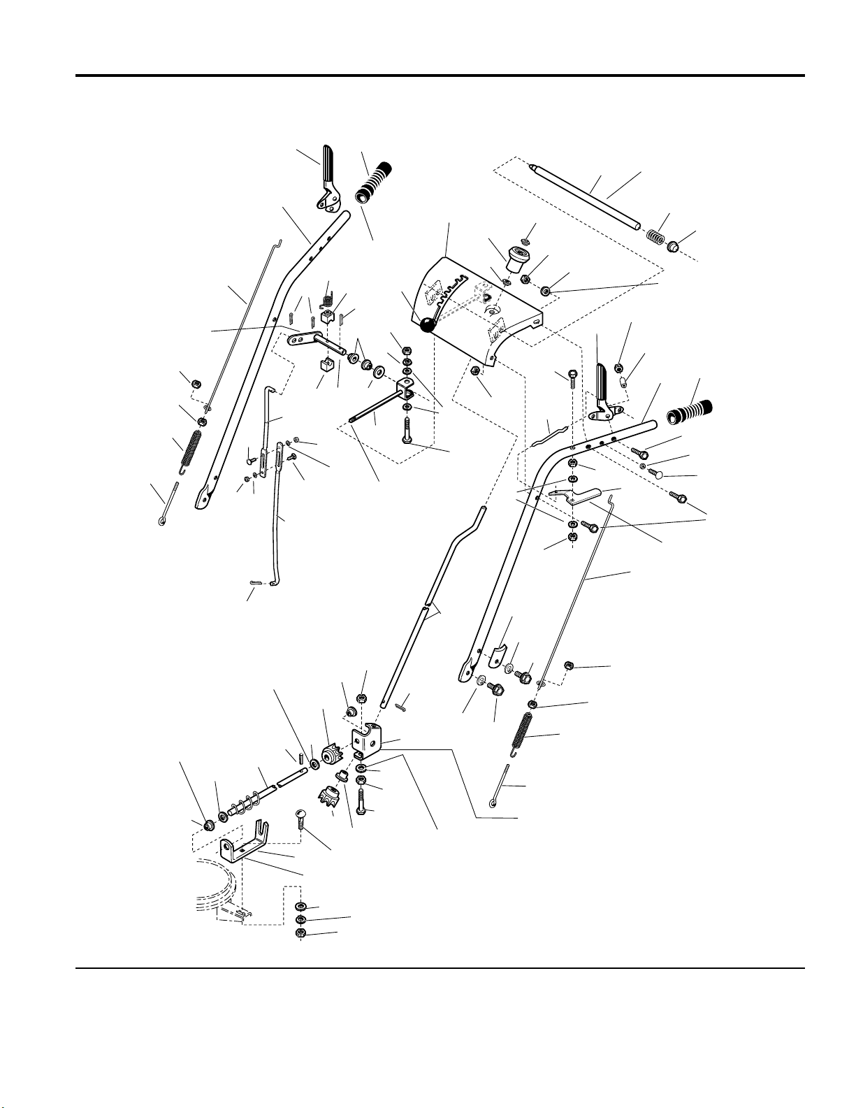
Handles and Controls Group
NOTE: Unless noted otherwise,
use the standard hardware torque
specification chart.
4
Insert shift rod (Ref. 13)
into inner hole of Ref. 15.
3
3
2
12
1
10
11
985917
6
5
8
14
14 15
13
12
9
7
Apply adhesive to
secure grips.
16
14
17
18
19
10
11
Shift rod assembly
(Ref. 20) must pivot
freely on pivot blocks
(Ref. 14).
20
11
10
23
24
22
24
21
26
25
28
1622
44
27
34
33
28
29
35
30
36
Must slide freely in
dash assembly (Ref 24).
Apply lubricant as required.
31
32
Ref. 29 required on
slotted holes only.
36
37
7
38
39
40
41
43
22
42
Must pivot freely
on capscrew (Ref 34).
Apply lubricant as required.
49
8
Use washers to shim
gear (Ref. 54) as required
to insure proper adjustment.
62
25
17
54
Mount bushings
with flange on
inside of brackets.
59
60
61
59
51
22
52
25
53
Locate under rear hole of
gear support (Ref. 51) only.
47
25
54
55
56
Slot in support (Ref. 56)
towards rear of unit.
57
58
The above parts group applies to the following Mfg. Nos.:
1694433 - 860E
1694434 - 860M
45
47
46
47
48
3
3
50
2
1
Position in slots of frame to be sure hub of gear
(Ref. 56) is tight against the inside surface of the
gear support (Ref. 51).
© Copyright Simplicity Manufacturing, Inc. All Rights Reserved.
2003
4
TP 400-3889-00-LW-S
Page 5

Handles and Controls Group
PART NO. DESCRIPTIONREF NO. QTY.
1 1668525 2 ROD, Control, Lower
2 1669323 2 S P R ING, Extens i on
3 1916621 4 NUT, Hex, #10-24 R.H.
4 1715132 1 CLUTCH ROD, Auger Drive
5 1722636 1 HANDLE, R.H. (Auger Control side)
6 1722638 1 LEVER, Auger Clutch, R.H.
7 1676954 2 GRIP, Black Vinyl, for 1" Tube
8 1918447 3 PI N , Co tter
9 1666255 1 ROD, Shift, Lower
10 1916622 3 NUT, Hex Head, 1/4-20
11 1916964 3 LOCKWASHER, Spring
12 1960252 2 CARRIAGE BOLT, 1/4-20 x 5/8
13 1720238 1 ROD, Shift, Upper
14 1668524 2 BLOCK, Pivot
15 1720240 1 ROD & ARM ASSEMBLY, Pivot
16 1715123 1 SPRING, Torsion
17 1918452 2 PIN, Cotter
18 1668185 2 BUSHING
19 1924361 1 WASHER
20 1668523 1 ROD & CLEVIS ASSEMBLY
21 1921159 1 CAPSCREW, Hex Head, 1/4-20 x 2-1/4
22 1921319 3 WASHER, Flat 1/4
23 172038 1 KNOB, Internal Thread, 3/8-16
24 1722627 1 DASHBOARD & SUPPORT ASSAMBLY
25 1667588 4 BUSHIN G, Nyl on
26 1714084 1 KNOB, Chute Control Spinner
27 1960093 1 NUT, Push, 3/8
28 1919438 4 NUT, Hex Lock ESNA Light, 5/16-18
29 1919326 2 WASHER, Flat 5/16
30 1722633 1 ROD & SPRING ASSEMBLY
31 1722690 1 SPRING, Compression
32 1960519 1 NUT, Push for 1/2" Stud
33 1722630 1 ROD, Free hand Control
34 1921962 1 CAPSCREW, Hex Head, 1/2-20 x 1 3/4
35 1722667 1 LEVER, L.H. (Traction Drive Clutch)
36 1923358 3 NUT, Hex, Centerlock, 1/4-20
37 1715655 2 SPACER, Large
38 1722637 1 HANDLE, L.H. (Traction Drive Control side)
39 1922837 2 CAPSCREW, Hex Head, 1/4-20 x 1-1/2
40 1715654 2 SPACER, Small
Footnotes
The above parts group applies to the following Mfg. Nos.:
1694433 - 860E
1694434 - 860M
© Copyright Simplicity Manufacturing, Inc. All Rights Reserved.
2003
5
TP 400-3889-00-LW-S
Page 6

Handles and Controls Group
NOTE: Unless noted otherwise,
use the standard hardware torque
specification chart.
4
Insert shift rod (Ref. 13)
into inner hole of Ref. 15.
3
3
2
12
1
10
11
985917
6
5
8
14
14 15
13
12
9
7
Apply adhesive to
secure grips.
16
14
17
18
19
10
11
Shift rod assembly
(Ref. 20) must pivot
freely on pivot blocks
(Ref. 14).
20
11
10
23
24
22
24
21
26
25
28
1622
44
27
34
33
28
29
35
30
36
Must slide freely in
dash assembly (Ref 24).
Apply lubricant as required.
31
32
Ref. 29 required on
slotted holes only.
36
37
7
38
39
40
41
43
22
42
Must pivot freely
on capscrew (Ref 34).
Apply lubricant as required.
49
8
Use washers to shim
gear (Ref. 54) as required
to insure proper adjustment.
62
25
17
54
Mount bushings
with flange on
inside of brackets.
59
60
61
59
51
22
52
25
53
Locate under rear hole of
gear support (Ref. 51) only.
47
25
54
55
56
Slot in support (Ref. 56)
towards rear of unit.
57
58
The above parts group applies to the following Mfg. Nos.:
1694433 - 860E
1694434 - 860M
45
47
46
47
48
3
3
50
2
1
Position in slots of frame to be sure hub of gear
(Ref. 56) is tight against the inside surface of the
gear support (Ref. 51).
© Copyright Simplicity Manufacturing, Inc. All Rights Reserved.
2003
6
TP 400-3889-00-LW-S
Page 7

Handles and Controls Group
PART NO. DESCRIPTIONREF NO. QTY.
41 1960556 2 CAPSCREW, Taptite, Pan Head, Torx, 1/4-20 x 3/4
42 1921221 4 CAPSCREW, Hex Head, 5/16-18 x 1-1/2
43 1722631 1 LEVER, Pivot
44 1920397 2 NUT, Hex Lock ESNA Light, 1/4-20
45 1715658 1 ROD, Chu te Control
46 1720452 2 CLAMP, Tube, Saddle
47 1917356 5 LOCKWASHER, 5/16
48 1922127 2 CAPSCREW, Hex Head 5/16-18 x 1-3/4
49 1715659 1 CLUTCH ROD, Traction Drive
50 1921332 2 CAPSCREW, Hex Head, 5/16-18 x 3/4
51 1718793 1 SUPPORT, Gear
52 1960518 2 NUT, Push
53 1960252 4 CARRIAGE BOLT, 1/4-20 x 5/8
54 1718593 2 GEAR, Steel, Universal (Supersedes Plastic Gear)
55 1931333 1 CARRIAGE BOLT, 5/16-18 X 3/4
56 1715099 1 BRACKET, Worm Support
57 1919326 1 WASHER, Flat 5/16
58 1917372 1 NUT, Hex, 5/16 -18
59 1960103 1 WASHER, Flat 3/8
60 1715117 1 WORM ASSEMBLY
61 916168 1 PIN, Spring
62 1960294 2 NUT, Hex Flange, Whiz Lock Small, 1/4-20
Footnotes
The above parts group applies to the following Mfg. Nos.:
1694433 - 860E
1694434 - 860M
© Copyright Simplicity Manufacturing, Inc. All Rights Reserved.
2003
7
TP 400-3889-00-LW-S
Page 8
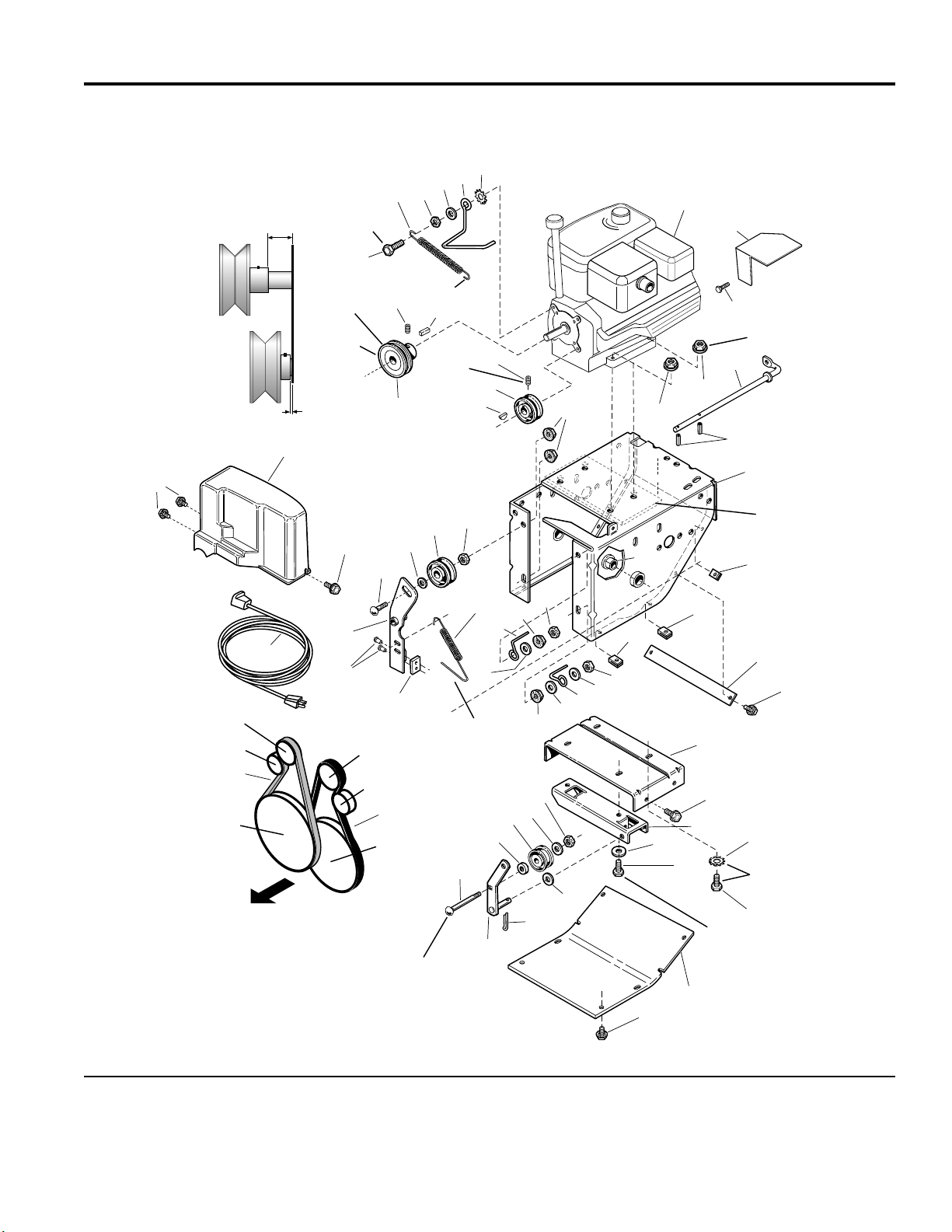
Engine and Frame Group - 8HP Electric Start
NOTE: Unless noted otherwise,
use the standard hardware torque
specification chart.
1.06"
Engine Pulley
(Auger)
Engine Pulley
(Traction Drive)
.056"
127
43
Leave .18" grip
between hex
nut and head
of cap screw.
1
Torque to
10 - 14 ft-lbs.
(2 places)
Install with
hub facing
engine.
27
40
44
Attach to
Idler arm
bottom hole.
48
49
41
45
42
3
2
50
Install with
hub facing
engine.
52
986356
4
5
51
15
Right rear only.
48
47
46
319
7
13
9
8
10
11
Engine
12
Engine Pulley
(Auger)
Idler Pulley
Auger Pulley
FRONT
(Auger)
36
39
6
338
18
17
37
Attach to Frame
16
19
12
12
14
16
17
18
17
15
19
20
Engine Pulley
34
(Traction Drive)
Idler Pulley
35
Traction
Drive Pulley
16
17
33
32
23
31
21
22
24
4
Required on rear
engine bolts only.
28
25
Torque all engine bolts
to 19 - 21 ft-lbs.
Use upper square hole on 5 HP
and lower square hole on 7 HP.
29
30
26
27
The above parts group applies to the following Mfg. Nos.:
1694433 - 860E
© Copyright Simplicity Manufacturing, Inc. All Rights Reserved.
2003
8
TP 400-3889-00-LW-S
Page 9

Engine and Frame Group - 8HP Electric Start
PART NO. DESCRIPTIONREF NO. QTY.
1 1921982 2 CAPSCREW, Hex Head, 5/16-24 x 1-1/4
2 1924874 1 WASHER, 5/16
3 1725424 1 BELT STOP
4 1920427 2 LOCKWASHER, External Tooth, 3/8
5 * 1 ENGINE, 8HP, Briggs & Stratton, Electric Start, Engine Model #
12E3940110E1
6 ** 1 CORD, Electric Start, (Not a Service Part)
7 1927557 3 NUT, Hex, Flange Whizlock, 5/16-18
8 1931277 1 NUT, Hex Flange Whiz Lock, 5/16-18
9 1715092 1 ROD, Idler
10 916169 2 PIN, Spring
11 1725339 1 FRAME
12 1926018 6 NUT, Speed 1/4-20
13 1666001 2 BUSHING
14 1715559 1 TIE BAR SUPPORT
15 1929477 6 CAPSCREW, Taptite, #10-24 x 1/2
16 1960251 3 NUT, Hex, Jam, Center-l o ck, 3/8-16
17 1924940 4 WASHER, Flat
18 1674315 2 GUIDE, Belt
19 1922694 4 NUT, Hex, Flange, Locking, 3/8-16
20 1715756 1 FRAME BRACKET
21 1924856 4 CAPSCREW, Taptite, 5/16-18 X 1/2
22 1715111 1 SUPPORT, Pivot
23 1919381 2 WASHER
24 1960585 3 CAPSCREW, Hex Head, 5/16-18 x 1-3/4
25 1922127 1 CAPSCREW, Hex Head, 5/16-18 x 1 3/4
26 1715137 1 COVER, Bot to m
27 1925003 9 CAPSCREW, Taptite, 1/4-20 x 1/2
28 1925125 1 WASHER, Flat 15/32
29 1918451 1 PIN, Cotter
30 1725369 1 ARM & SHAFT ASSEMBLY, Idler
31 1960268 1 CARRIAGE BOLT, 3/8-16 X 1-1/4
32 174870 1 SPACER
33 118414 1 PULLEY, Idler - Traction Drive
34 1717393 1 V-BELT, 4L, Auger Drive
35 1725371 1 V-BELT, 3L Traction Drive
36 1715118 1 SPRING, Extension
37 1669313 1 PAD, Brake
38 925160 2 RIVET , Pop
39 1717319 1 ARM & HUB ASSEMBLY, Idler/Brake (Includes Reference Numbers 37 & 38)
40 1931353 1 CARRIAGE BOLT, 3/8-16 x 1-3/4
Footnotes
* See your local Briggs & Stratton distributor for Parts & Service.
** Not a Servic e P ar t.
The above parts group applies to the following Mfg. Nos.:
1694433 - 860E
© Copyright Simplicity Manufacturing, Inc. All Rights Reserved.
2003
9
TP 400-3889-00-LW-S
Page 10

Engine and Frame Group - 8HP Electric Start
NOTE: Unless noted otherwise,
use the standard hardware torque
specification chart.
1.06"
Engine Pulley
(Auger)
Engine Pulley
(Traction Drive)
.056"
127
43
Leave .18" grip
between hex
nut and head
of cap screw.
1
Torque to
10 - 14 ft-lbs.
(2 places)
Install with
hub facing
engine.
27
40
44
Attach to
Idler arm
bottom hole.
48
49
41
45
42
3
2
50
Install with
hub facing
engine.
52
986356
4
5
51
15
Right rear only.
48
47
46
319
7
13
9
8
10
11
Engine
12
Engine Pulley
(Auger)
Idler Pulley
Auger Pulley
FRONT
(Auger)
36
39
6
338
18
17
37
Attach to Frame
16
19
12
12
14
16
17
18
17
15
19
20
Engine Pulley
34
(Traction Drive)
Idler Pulley
35
Traction
Drive Pulley
16
17
33
32
23
31
21
22
24
4
Required on rear
engine bolts only.
28
25
Torque all engine bolts
to 19 - 21 ft-lbs.
Use upper square hole on 5 HP
and lower square hole on 7 HP.
29
30
26
27
The above parts group applies to the following Mfg. Nos.:
1694433 - 860E
© Copyright Simplicity Manufacturing, Inc. All Rights Reserved.
2003
10
TP 400-3889-00-LW-S
Page 11

Engine and Frame Group - 8HP Electric Start
PART NO. DESCRIPTIONREF NO. QTY.
41 1922755 1 WASHER, 3/8
42 1668477 1 PULLEY, Idler - Auger Drive
43 1725379 1 COVER, Belt
44 159106 1 SPRING, Extension
45 920438 1 NUT, Hex, Jam, 5/16-2 4
46 924819 1 KEY, Hi-Pro, 1/8 x 5/8
47 1674325 1 PULLEY, Engine - Traction Drive
48 1960619 2 SET SCREW, Hex Socket Cup Point, 5/16-18 x 5/16
49 1720313 1 PULLEY, Engine - Auger Drive
50 905850 1 KEY, Parallel, 3/16 x 3/16
51 1725665 1 GUARD, Muffler
52 1930645 1 NUT, Hex Flange Lock, 3/8-16
Footnotes
* See your local Briggs & Stratton distributor for Parts & Service.
** Not a Servic e P ar t.
The above parts group applies to the following Mfg. Nos.:
1694433 - 860E
© Copyright Simplicity Manufacturing, Inc. All Rights Reserved.
2003
11
TP 400-3889-00-LW-S
Page 12

Engine and Frame Group - 8HP Manual Start
NOTE: Unless noted otherwise,
use the standard hardware torque
specification chart.
1.06"
Engine Pulley
(Auger)
Engine Pulley
(Traction Drive)
.056"
127
43
Leave .18" grip
between hex
nut and head
of cap screw.
1
Torque to
10 - 14 ft-lbs.
(2 places)
Install with
hub facing
engine.
27
40
44
Attach to
Idler arm
bottom hole.
48
49
41
45
42
3
2
50
Install with
hub facing
engine.
6
986357
4
5
Right rear only.
48
47
46
319
7
13
9
8
10
11
Engine
12
Engine Pulley
(Auger)
Idler Pulley
Auger Pulley
FRONT
(Auger)
19
16
12
12
39
36
18
14
338
37
17
Attach to Frame
19
17
18
17
16
15
20
Engine Pulley
34
(Traction Drive)
Idler Pulley
35
Traction
Drive Pulley
31
32
33
17
16
23
24
22
21
4
Required on rear
engine bolts only.
28
25
Torque all engine bolts
to 19 - 21 ft-lbs.
Use upper square hole on 5 HP
and lower square hole on 7 HP.
29
30
26
27
The above parts group applies to the following Mfg. Nos.:
1694434 - 860M
© Copyright Simplicity Manufacturing, Inc. All Rights Reserved.
2003
12
TP 400-3889-00-LW-S
Page 13

Engine and Frame Group - 8HP Manual Start
PART NO. DESCRIPTIONREF NO. QTY.
1 1921982 2 CAPSCREW, Hex Head, 5/16-24 x 1-1/4
2 1924874 1 WASHER, 5/16
3 1725424 1 BELT STOP
4 1920427 2 LOCKWASHER, External Tooth, 3/8
5 * 1 ENGINE, 8HP, Briggs & Stratton, Manual Start, Engine Model #
12E3960111E1
6 1930645 1 NUT, Hex Flange Lock, 3/8-16
7 1927557 3 NUT, Hex, Flange Whizlock, 5/16-18
8 1931277 1 NUT, Hex Flange Whiz Lock, 5/16-18
9 1715092 1 ROD, Idler
10 916169 2 PIN, Spring
11 1725339 1 FRAME
12 1926018 6 NUT, Speed 1/4-20
13 1666001 2 BUSHING
14 1715559 1 TIE BAR SUPPORT
15 1929477 2 CAPSCREW, Taptite, #10-24 x 1/2
16 1960251 3 NUT, Hex, Jam, Center-l o ck, 3/8-16
17 1924940 4 WASHER, Flat
18 1674315 2 GUIDE, Belt
19 1922694 4 NUT, Hex, Flange, Locking, 3/8-16
20 1715756 1 FRAME BRACKET
21 1924856 4 CAPSCREW, Hex Head, Taptite, 5/16-18 X 1/2
22 1715111 1 SUPPORT, Pivot
23 1919381 2 WASHER
24 1960585 3 CAPSCREW, Hex Head, 5/16-18 x 1-3/4
25 1922127 1 CAPSCREW, Hex Head, 5/16-18 x 1 3/4
26 1715137 1 COVER, Bot to m
27 1925003 9 CAPSCREW, Taptite, 1/4-20 x 1/2
28 1925125 1 WASHER, Flat 15/32
29 1918451 1 PIN, Cotter
30 1725369 1 ARM & SHAFT ASSEMBLY, Idler
31 1960268 1 CARRIAGE BOLT, 3/8-16 X 1-1/4
32 174870 1 SPACER
33 118414 1 PULLEY, Idler - Traction Drive
34 1717393 1 V-BELT, 4L, Auger Drive
35 1725371 1 V-BELT, 3L Traction Drive
36 1715118 1 SPRING, Extension
37 1669313 1 PAD, Brake
38 925160 2 RIVET , Pop
39 1717319 1 ARM & HUB ASSEMBLY, Idler/Brake (Includes Reference Numbers 37 & 38)
40 1931353 1 CARRIAGE BOLT, 3/8-16 x 1-3/4
Footnotes
* See your local Briggs & Stratton distributor for Parts & Service.
The above parts group applies to the following Mfg. Nos.:
1694434 - 860M
© Copyright Simplicity Manufacturing, Inc. All Rights Reserved.
2003
13
TP 400-3889-00-LW-S
Page 14

Engine and Frame Group - 8HP Manual Start
NOTE: Unless noted otherwise,
use the standard hardware torque
specification chart.
1.06"
Engine Pulley
(Auger)
Engine Pulley
(Traction Drive)
.056"
127
43
Leave .18" grip
between hex
nut and head
of cap screw.
1
Torque to
10 - 14 ft-lbs.
(2 places)
Install with
hub facing
engine.
27
40
44
Attach to
Idler arm
bottom hole.
48
49
41
45
42
3
2
50
Install with
hub facing
engine.
6
986357
4
5
Right rear only.
48
47
46
319
7
13
9
8
10
11
Engine
12
Engine Pulley
(Auger)
Idler Pulley
Auger Pulley
FRONT
(Auger)
19
16
12
12
39
36
18
14
338
37
17
Attach to Frame
19
17
18
17
16
15
20
Engine Pulley
34
(Traction Drive)
Idler Pulley
35
Traction
Drive Pulley
31
32
33
17
16
23
24
22
21
4
Required on rear
engine bolts only.
28
25
Torque all engine bolts
to 19 - 21 ft-lbs.
Use upper square hole on 5 HP
and lower square hole on 7 HP.
29
30
26
27
The above parts group applies to the following Mfg. Nos.:
1694434 - 860M
© Copyright Simplicity Manufacturing, Inc. All Rights Reserved.
2003
14
TP 400-3889-00-LW-S
Page 15

Engine and Frame Group - 8HP Manual Start
PART NO. DESCRIPTIONREF NO. QTY.
41 1922755 1 WASHER, 3/8
42 1668477 1 PULLEY, Idler - Auger Drive
43 1725379 1 COVER, Belt
44 159106 1 SPRING, Extension
45 920438 1 NUT, Hex, Jam, 5/16-2 4
46 924819 1 KEY, Hi-Pro, 1/8 x 5/8
47 1674325 1 PULLEY, Engine - Traction Drive
48 1960619 2 SET SCREW, Hex Socket Cup Point, 5/16-18 x 5/16
49 1720313 1 PULLEY, Engine - Auger Drive
50 905850 1 KEY, Parallel, 3/16 x 3/16
Footnotes
* See your local Briggs & Stratton distributor for Parts & Service.
The above parts group applies to the following Mfg. Nos.:
1694434 - 860M
© Copyright Simplicity Manufacturing, Inc. All Rights Reserved.
2003
15
TP 400-3889-00-LW-S
Page 16

Auger and Impeller Group - 24"
NOTE: Unless noted otherwise,
use the standard hardware torque
specification chart.
Apply a bead of gasket eliminator
into rear se al groove and flat surface
just past groove (Ref. 15 & 20) on both
halves. Also, apply to bushing bore surface.
Be careful not t o over apply as excess will
cause lip seal t o not function properly.
13
14
15
16
17
18
12
11
30
19
986355
1
Torque to
30 - 44 ft-lbs.
4
5
2
3
6
9
7
3
Torque (Ref. 2) to
17 - 22 ft-lbs.
10
8
Locate pulley on worm shaft
(Ref. 10) so the belt is 1.94"
from rear of impeller housing.
3
17
20
21
Torque to
9 - 11 ft-lbs.
Hub of pulle y
to face auger.
2
Apply grease unt il it appears
at ends of auger assembly.
Auger stamped "R".
24
23
25
26
13
22
27
Auger stamped "L".
28
29
Place 1 or 2 washers
per side as re quired.
The above parts group applies to the following Mfg. Nos.:
1694433 - 860E
1694434 - 860M
© Copyright Simplicity Manufacturing, Inc. All Rights Reserved.
2003
16
TP 400-3889-00-LW-S
Page 17

Auger and Impeller Group - 24"
PART NO. DESCRIPTIONREF NO. QTY.
1 1715091 1 PULLEY, Auger Drive
2 1930540 2 SETSCREW, Square Head Cup Point, 3/8-18 x 5/8
3 905123 3 KEY, Woodruff, 3/16 x 3/4
4 1960474 1 SETSCREW, Square Head Cup Point, 3/8-16 x 1/2
5 1715120 1 IMPELLER
6 1612093 1 SEAL, Oil
7 1666425 1 BUSHING
8 936098 1 PIN, Drive-Lock 3/16 x 1-1/2
9 1721680 1 THRUST COLLAR
10 1660655 1 SHAFT, Worm
11 1670971 1 WASHER, Thrust
12 1666424 1 BUSHING
13 1676027 2 SEAL, Oil
14 1923358 6 NUT, Lock, 1/4-2 0
15 1721684 1 GEAR CASE COVER, R.H.
16 1721676 1 GASKET
17 1676026 2 BUSHING
18 1725349 1 SHAFT, Auger
19 1676024 1 GEAR, Worm
20 1721685 1 GEAR CASE COVER, L.H.
21 960625 1 PIPE PLUG, 1/8 NPT
22 1924009 6 CAPSCREW, Hex Head, 1/4-20 x 7/8
23 921133 2 GREASE FITTING
24 1718781 1 AUGER, R.H. 22" , Serra te d
25 1718780 1 AUGER, L.H. 22", Serra te d
26 1918447 2 PIN, Cotter 3/32 x 3/4
27 1668344 2 PIN, Shear
28 1960114 4 WASHER
29 927794 2 RING, Retaining
30 1612112 1 TUBE
Footnotes
The above parts group applies to the following Mfg. Nos.:
1694433 - 860E
1694434 - 860M
© Copyright Simplicity Manufacturing, Inc. All Rights Reserved.
2003
17
TP 400-3889-00-LW-S
Page 18

Auger Housing and Chute Group - 24"
NOTE: Unless noted otherwise,
use the standard hardware torque
specification chart.
26
Place Ref. 3
between chute
and deflector.
29
28
27
986360
Seal must
cover openings
at hinge pivot.
4
3
1
2
8
5
6
7
9
10
25
25
24
Mounts to underside
of housing.
23
21
22
20
11
12
Coat top and bottom of
chute ring with grease.
13
14
15
16
18
17
19
The above parts group applies to the following Mfg. Nos.:
1694433 - 860E
1694434 - 860M
© Copyright Simplicity Manufacturing, Inc. All Rights Reserved.
2003
18
TP 400-3889-00-LW-S
Page 19

Auger Housing and Chute Group - 24"
PART NO. DESCRIPTIONREF NO. QTY.
1 1670578 1 KNOB
2 1919326 1 WASHER, Flat, 5/16
3 960210 1 WASHER, Nylon
4 1706085 2 DECAL, Hinge, Orange
5 1715115 1 CHUTE & DEFLECTOR ASSEMBLY
6 1931333 1 CARRIAGE BOLT, 5/16-18 x 3/4
7 1960126 2 NUT, Push, 1/4
8 1612455 1 CHUTE, Guard
9 1925205 4 CAPSCREW, Hex Head, 5/16-18 x 5/8
10 1917356 3 LOCKWASHER, 5/16
11 1665982 1 RETAINER, Bearin g
12 108202 1 BEARING, Ball
13 1725341 1 HOUSING ASSEMBLY 24"
14 1722649 1 AUGER PLATE, L.H. End
15 1666001 2 BUSHING
16 177434 2 SKID, Snowthrower (Set of 2 available under PN 1685501)
17 1924940 4 WASHER, Flat, 13/32 x 7/8 x 5/64
18 1916965 4 LOCKWASHER, 3/8
19 1916950 4 NUT, Hex Head, 3/8-16
20 1931348 4 CARRIAGE BOLT, 3/8-16 x 3/4
21 1725352 1 BLADE, Scraper
22 1927428 5 CAPSCREW, Taptite, 1/4-20 x 3/8
23 1930659 3 NUT, Retainer, 5/16-18
24 1930641 12 NUT, Hex Flange, Whiz-Lock, 1/4-20
25 1722650 1 AUGER PLATE, R.H. End
26 1931315 11 CARRIAGE BOLT, 1/4-20 x 1/2
27 1666613 2 HOLD DOWN, Chute
28 1667865 2 SPRING, Flat
29 1960001 2 CAPSCREW, Hex Washer Head, Plastite #10-14 x 5/8
Footnotes
The above parts group applies to the following Mfg. Nos.:
1694433 - 860E
1694434 - 860M
© Copyright Simplicity Manufacturing, Inc. All Rights Reserved.
2003
19
TP 400-3889-00-LW-S
Page 20

Traction Drive Group
NOTE: Unless noted otherwise,
use the standard hardware torque
specification chart.
10
9
11
12
13
Apply loctite
(2 places).
Remove all play out of axle by
moving axle to left, move set
collar (Ref. 27) to the right to
take all play out of sprocket
assembly (Ref. 29) and tighten.
Befiore making this adjustment
be sure tie bar support (see Frame Group)
Is installed between frame sides.
33
Torque to
10 - 14 ft-lbs.
28
32
Retainer to be
loacted inside frame.
14
Coat with
synthetic 5W-50
motor oil.
Torque to
10 - 14 ft-lbs.
27
38
34
35
36
37
15
17
16
28
Tighten when all parts are
tight against shoulder of hub.
Maximum gap between Ref 19
and 22 when assembled .005" - .007".
18
19
29
39
Apply anti-seize
to both ends.
40
47
Apply loctite to
screws and torque
to 55 - 60 in-lbs
(2 places).
12
13
20
19
41
Bell crank must
pivot freely.
3
4
21
13
22
23
Retainer to be
loacted inside frame.
31
30
11
2
Pack groove
with grease.
6
5
12
10
25
Apply locktite and
torque to 8 - 10 ft. lbs.
SC984936
1
7
8
9
24
26
41
Earred end
With hub (Ref. 32) away from pivot arm
assembly (Ref. 35), tighten so that drive disk
(Ref. 39) has no play, but is still free rotate.
The above parts group applies to the following Mfg. Nos.:
1694433 - 860E
1694434 - 860M
© Copyright Simplicity Manufacturing, Inc. All Rights Reserved.
2003
42
20
43
44
45
46
TP 400-3889-00-LW-S
Page 21

Traction Drive Group
PART NO. DESCRIPTIONREF NO. QTY.
1 1930601 3 CAPSCREW, Taptite, 5/16-18 x 5/8
2 1673994 1 BRACKET
3 1916950 1 NUT, Hex, 3/8-16
4 1916965 1 LOCKWASHER, 3/8
5 1669256 1 SHIFT ARM ASSEMBLY, w/Bushing
6 1666114 1 BUSHING
7 1924940 1 WASHER
8 1923701 1 CAPSCREW, Hex Head, 3/8-16 x 2
9 1925205 3 CAPSCREW, Hex Head, 5/16-18 x 5/8
10 1705897 2 BEARING, Ball
11 1667341 2 RETAINER, Bearin g
12 1917356 7 LOCKWASHER, 5/16
13 1917372 7 NUT, Hex, 5/16 -18
14 1715093 1 SHAFT, Hex
15 927794 1 E-RING, Retaining
16 1921332 3 CAPSCREW, Hex Head, 5/16-18 x 3/4
17 1725428 1 DISC, Fric tion
18 1665995 1 HUB, Friction Disc
19 1678956 2 COLLAR, Thrust
20 1666207 1 PIN, Loop
21 1960348 2 SET SCREW, Hex Socket, Cup Point, 1/4-20 x 3/8
22 1667335 1 COLLAR, Set
23 1715094 1 SPROCKET, 10T
24 1960353 1 WASHER
25 1916964 1 LOCKWASHER, 1/4
26 1923341 1 CAPSCREW, Hex Head, 1/4-20 x 3/4
27 8021010 1 COLLAR, Set
28 1928721 2 SET SCREW, Square Head, Cup Point, 5/16-18 x 1/2
29 1715095 1 AXLE & SPROCKET ASSEMBLY
30 1715130 1 CHAIN, Roller, #40 x 25
31 1715101 1 BUSHING
32 1715253 1 PULLEY, Traction
33 1935048 2 NUT, Centerlock, Hex Flange Head, 5/16-18
34 1665844 2 SPACER
35 1715734 1 PIVOT ASSEMBLY
36 1925205 2 CAPSCREW, Hex Head, 5/16-18 x 5/8
37 1960114 1 WASHER
38 930672 1 KEY, Hi-Pro
39 1719879 1 DRIVE, Disc, w/Spindle
40 1715131 1 PIVOT ROD
Footnotes
The above parts group applies to the following Mfg. Nos.:
1694433 - 860E
1694434 - 860M
© Copyright Simplicity Manufacturing, Inc. All Rights Reserved.
2003
21
TP 400-3889-00-LW-S
Page 22

Traction Drive Group
NOTE: Unless noted otherwise,
use the standard hardware torque
specification chart.
10
9
11
12
13
Apply loctite
(2 places).
Remove all play out of axle by
moving axle to left, move set
collar (Ref. 27) to the right to
take all play out of sprocket
assembly (Ref. 29) and tighten.
Befiore making this adjustment
be sure tie bar support (see Frame Group)
Is installed between frame sides.
33
Torque to
10 - 14 ft-lbs.
28
32
Retainer to be
loacted inside frame.
14
Coat with
synthetic 5W-50
motor oil.
Torque to
10 - 14 ft-lbs.
27
38
34
35
36
37
15
17
16
28
Tighten when all parts are
tight against shoulder of hub.
Maximum gap between Ref 19
and 22 when assembled .005" - .007".
18
19
29
39
Apply anti-seize
to both ends.
40
47
Apply loctite to
screws and torque
to 55 - 60 in-lbs
(2 places).
12
13
20
19
41
Bell crank must
pivot freely.
3
4
21
13
22
23
Retainer to be
loacted inside frame.
31
30
11
2
Pack groove
with grease.
6
5
12
10
25
Apply locktite and
torque to 8 - 10 ft. lbs.
SC984936
1
7
8
9
24
26
41
Earred end
With hub (Ref. 32) away from pivot arm
assembly (Ref. 35), tighten so that drive disk
(Ref. 39) has no play, but is still free rotate.
The above parts group applies to the following Mfg. Nos.:
1694433 - 860E
1694434 - 860M
© Copyright Simplicity Manufacturing, Inc. All Rights Reserved.
2003
42
22
43
44
45
46
TP 400-3889-00-LW-S
Page 23

Traction Drive Group
PART NO. DESCRIPTIONREF NO. QTY.
41 1918451 2 PIN, Cotter 1/8 x 3/4
42 1919438 1 NUT, Hex Lock, ESNA, 5/16-18
43 1919326 1 WASHER, Flat
44 1700473 1 BELLCRANK
45 1666106 1 BUSHING
46 1922127 1 CAPSCREW, Hex Head, 5/16-18 x 1-3/4
47 1924366 1 WASHER
Footnotes
The above parts group applies to the following Mfg. Nos.:
1694433 - 860E
1694434 - 860M
© Copyright Simplicity Manufacturing, Inc. All Rights Reserved.
2003
23
TP 400-3889-00-LW-S
Page 24

Wheels & Tires Group
NOTE: Unless noted otherwise,
use the standard hardware torque
specification chart.
SC984933
6
5
4
3
1
2
The above parts group applies to the following Mfg. Nos.:
1694433 - 860E
1694434 - 860M
© Copyright Simplicity Manufacturing, Inc. All Rights Reserved.
2003
24
TP 400-3889-00-LW-S
Page 25

Wheels & Tires Group
PART NO. DESCRIPTIONREF NO. QTY.
1 1666969 2 KLIK-PIN
2 172353 2 VALVE STEM & CAP
3 1664090 2 TUB E, Tire
4 1723286 2 WHEEL
5 1723287 2 TIRE
6 1723169 2 WHEEL & TIRE ASSEMBLY, (Includes Ref. 2-5)
Footnotes
The above parts group applies to the following Mfg. Nos.:
1694433 - 860E
1694434 - 860M
© Copyright Simplicity Manufacturing, Inc. All Rights Reserved.
2003
25
TP 400-3889-00-LW-S
Page 26

Decals Group - 860
NOTE: Unless noted otherwise,
use the standard hardware torque
specification chart.
yy
WARNING
TOAVOID SERIOUS INJURY
Read Owner s Ma nual befor e operating unit.
Never allow children to operate snowthr ower.
Always direct discharge chute so as to avoid injur y
to persons —or da mage to pr ope rty
Stop engine and disconnect spar k plug wir e before
removing debris or servicing unit.
Keep all shields and guar ds in place while r unning.
1
2
D986358
3
1
2
11
4
7
3
4
13
6
8
7
1716532
8
6
10
5
9
11
10
12
The above parts group applies to the following Mfg. Nos.:
1694433 - 860E
1694434 - 860M
© Copyright Simplicity Manufacturing, Inc. All Rights Reserved.
2003
26
TP 400-3889-00-LW-S
Page 27

Decals Group - 860
PART NO. DESCRIPTIONREF NO. QTY.
1 1722640 1 DECAL, Auger Control
2 1715557 1 DECAL, Speed Selector
3 1722639 1 DECAL, Warning / Main Dash Panel (Export)
3 1722643 1 DECAL, Warning / Main Dash Panel
4 1715558 1 DECAL, Simplicity Logo
5 * 1 DECAL, OPEI (Not Serviced)
6 1716532 1 DECAL, Auger Danger
6 1722642 1 DECAL, Auger Danger (Export)
7 1725374 1 DECAL, Stripe
8 1722641 1 DECAL, Discharge Chute Danger (Export)
8 1722674 1 DECAL, Discharge Chute Danger
9 * 1 I.D. Tag (N ot Serviced)
10 1720454 1 DECAL, Touch-up Paint
11 1722867 1 DECAL, Handle Lubrication
12 * 1 DECAL, Patent, Not Shown, (Not Serviced)
13 1706085 2 DECAL, Hinge, Orange
Footnotes
* Not a Service Part.
The above parts group applies to the following Mfg. Nos.:
1694433 - 860E
1694434 - 860M
© Copyright Simplicity Manufacturing, Inc. All Rights Reserved.
2003
27
TP 400-3889-00-LW-S
Page 28

Page 29

Hardware Identification & Torque Specifications
Common Hardware Types
Hex Head Capscrew
Carriage Bolt
Standard Hardware Sizing
When a washer or nut is identified as 1/2”, this is the
Nominal size
second number is present it represent the
When bolt or capscrew is identified as 1/2 - 16 x 2”, this
means the
second number represents the
example, and the final number is the
bolt or screw (in this example 2 inches long).
, meaning the
Nominal size
inside diameter
, or
body diameter
threads per inch
body length
Washer
Lockwasher
Hex Nut
is 1/2 inch; if a
threads per inch
is 1/2 inch; the
(16 in this
of the
The guides and ruler furnished below are designed to
help you select the appropriate hardware and tools.
0
1/4 3/4
1/2
Nut, 1/2”
Inside
Diameter
1
1/4 3/4
1/2
Screw, 1/2 x 2
2
1/4 3/4
1/2
3
1/4 3/4
1/2
4
Body
Diameter
Body
Length
Torque Specification Chart
FOR STANDARD MACHINE HARDWARE (Tolerance ± 20%)
Hardware
Grade
Size Of
Hardware ft/lbs Nm. ft/lbs Nm. ft/lbs Nm.
8-32
8-36
10-24
10-32
1/4-20
1/4-28
5/16-18 11 15.0 17 23.1 25 34.0
5/16-24 12 16.3 19 25.8 27 34.0
3/8-16 20 27.2 30 40.8 45 61.2
3/8-24 23 31.3 35 47.6 50 68.0
7/16-14 30 40.8 50 68.0 70 95.2
7/16-20 35 47.6 55 74.8 80 108.8
1/2-13 50 68.0 75 102.0 110 149.6
1/2-20 55 74.8 90 122.4 120 163.2
9/16-12 65 88.4 110 149.6 150 204.0
9/16-18 75 102.0 120 163.2 170 231.2
5/8-11 90 122.4 150 204.0 220 299.2
5/8-18 100 136 180 244.8 240 326.4
3/4-10 160 217.6 260 353.6 386 525.0
3/4-16 180 244.8 300 408.0 420 571.2
7/8-9 140 190.4 400 544.0 600 816.0
7/8-14 155 210.8 440 598.4 660 897.6
1-8 220 299.2 580 788.8 900 1,244.0
1-12 240 326.4 640 870.4 1,000 1,360.0
1. These torque values are to be used for all hardware
excluding: locknuts, self-tapping screws, thread forming
screws, sheet metal screws and socket head setscrews.
2. Recommended seating torque values for locknuts:
a. for prevailing torque locknuts - use 65% of grade 5
torques.
b. for flange whizlock nuts and screws - use 135% of
grade 5 torques.
3. Unless otherwise noted on assembly drawings, all torque
values must meet this specification.
No
Marks
SAE Grade 2 SAE Grade 5 SAE Grade 8
in/lbs in/lbs
19
2.1
20
2.3
27
3.1
31
3.5
66
7.6 8 10.9 12 16.3
76
8.6 10 13.6 14 19.0
30
31
43
49
NOTES
3.4
3.5
4.9
5.5
in/lbs
41
43
60
68
4.6
4.9
6.8
7.7
Wrench & Fastener Size Guide
1/4
1/4” Bolt or Nut
Wrench—7/16”
5/16
5/16” Bolt or Nut
Wrench—1/2”
3/8
3/8” Bolt or Nut
Wrench—9/16”
7/16
DIA.
7/16” Bolt or Nut
Wrench (Bolt)—5/8”
Wrench (Nut)—11/16”
1/2
DIA.
1/2” Bolt or Nut
Wrench—3/4”
Page 30

MANUFACTURING, INC.
500 N. Spring Street / PO Box 997
Port Washington, WI 53074-0997 USA
www.simplicitymfg.com
© Copyright Simplicity Manufacturing, Inc.
All Rights Reserved. Printed In USA.
2003
 Loading...