

Page 1

How to use this file...(Operators Manuals)
————————————————————————————————————————————–––
Instructions for
Print Vendors (Paper Manuals)
Paper Size: * 11 x 17
* Body—50 lbs brilliant white offset or equivalent.
* Cover—on pre-printed two-tone “Swash” stock.
Press: * Body—1-color, 2-sided
* Cover imprint —1-color, 1-sided
Bindery:* Saddle Stitch, Face Trim
* Face Trim
COVERS:* This file may contain several manuals, which differ only in their covers.
* Covers are all present at the beginning of this file.
* Back cover for a particular manual is the page IMMEDIATELY AFTER the front cover.
• Check the front cover for the individual part number (typically a 171xxxx number).
BODY: • The body of the manual is identical, regardless of the cover used.
* REMEMBER: ODD number pages are ALWAYS right hand pages, and EVEN number are ALWAYS
left hand pages.
General: * This instruction page is NOT part of the manual and must NOT be printed.
• Pages labeled with the text “THIS PAGE INTENTIONALLY BLANK” are placement pages ONLY,
and should NOT be printed.
————————————————————————————————————————————–––
Page 2

THIS PAGE INTENTIONALLY BLANK
Page 3
OPERATOR’S
MANUAL
Rear Tine Tiller
5.5HP Rear Tine Tiller
Mfg. No. Description
1693847 5HP Rear Tine Tiller
6.5HP Rear Tine Tiller
Mfg. No. Description
1693848 6HP Rear Tine Tiller
1721526-00
Rev 1/2001
TP 100-2485-00-RT-S
Page 4

MANUFACTURING, INC.
500 N Spring Street / PO Box 997
Port Washington, WI 53074-0997
www.simplicitymfg.com
© Copyright 2001 Simplicity Manufacturing, Inc.
All Rights Reserved. Printed in USA.
Page 5
TT
ABLE OF CONTENTSABLE OF CONTENTS
T
ABLE OF CONTENTS
TT
ABLE OF CONTENTSABLE OF CONTENTS
OPERAOPERA
OPERA
OPERAOPERA
SAFETY SIGNS & DECALSSAFETY SIGNS & DECALS
SAFETY SIGNS & DECALS
SAFETY SIGNS & DECALSSAFETY SIGNS & DECALS
FEAFEA
FEA
FEAFEA
CONTRCONTR
CONTR
CONTRCONTR
ADJUSTMENTSADJUSTMENTS
ADJUSTMENTS
ADJUSTMENTSADJUSTMENTS
OPERAOPERA
OPERA
OPERAOPERA
TION SAFETYTION SAFETY
TION SAFETY
TION SAFETYTION SAFETY
Owner's Responsibility ............................................. 2
Cautions and Important Notes.................................. 2
Important Safety Instructions.................................... 2
Safety Decals ........................................................... 4
TURESTURES
TURES
TURESTURES
Drive Safety Control Levers ...................................... 6
Rev erse Handle........................................................ 7
Engine Controls........................................................ 8
Wheel Lockouts........................................................ 9
Handlebar Height Adjustment................................. 10
Depth Regulator Lever ........................................... 11
Belt T ension Adjustment ......................................... 12
Pre-Start Inspection ............................................... 13
Starting and Stopping the Engine ........................... 13
Tilling...................................................................... 14
......................................................................................................................
........................................................... 5
......................................................................................................................
OLSOLS
....................................................................................................................
OLS
.......................................................... 6
OLSOLS
....................................................................................................................
........................................................................................................
.................................................... 9
........................................................................................................
TIONTION
..............................................................................................................
TION
....................................................... 13
TIONTION
..............................................................................................................
..................................................................................
......................................... 1
..................................................................................
......................................................................................
........................................... 2
......................................................................................
....................................................................
.................................. 4
....................................................................
Table Of Contents
TIPSTIPS
........................................................................................................................................
TIPS
.................................................................... 15
TIPSTIPS
........................................................................................................................................
Tilling Tips .............................................................. 15
Cultivating Tips ....................................................... 15
MAINTENANCE AND STMAINTENANCE AND ST
MAINTENANCE AND ST
MAINTENANCE AND STMAINTENANCE AND ST
Check Forward Belt T ension................................... 16
Check Rev erse Belt T ension................................... 16
Change Forward/Re verse Belt................................ 17
Check or Fill Engine Crankcase ............................. 18
Check Tiller T r ansmission Grease .......................... 19
Check Tire Pressure ............................................... 19
Lubrication.............................................................. 19
Clean Tine Axle Shaft............................................. 19
Engine Maintenance............................................... 20
Prepare for Storage................................................21
Tiller and Engine Maintenance Schedule ............... 21
TRTR
OUBLESHOOOUBLESHOO
TR
OUBLESHOO
TRTR
OUBLESHOOOUBLESHOO
T roub leshooting Guide............................................ 22
SPECIFICASPECIFICA
SPECIFICA
SPECIFICASPECIFICA
Features................................................................. 24
Technical Manual Availability .................................. 24
TING AND REPTING AND REP
TING AND REP
TING AND REPTING AND REP
TIONSTIONS
TIONS
TIONSTIONS
ORAORA
GEGE
ORA
ORAORA
..............................................................................................
............................................... 24
..............................................................................................
..................................................
GE
......................... 16
GEGE
..................................................
AIRAIR
......................................
AIR
................... 22
AIRAIR
......................................
CAUTION
You must read, understand and comply with all safety
and operating instructions in this manual before
attempting to setup and operate this equipment.
Failure to comply with all safety and operating
instructions can result in loss of machine control,
serious personal injury to you and/or bystanders, and
risk of equipment and property damage. The triangle
in the text signifies important cautions or warnings
which must be followed.
CAUTION
Engine exhaust from this product contains chemicals
known, in certain quantities, to cause cancer, birth
defects, or other reproductiv e harm.
FF
or easy refor easy ref
F
or easy ref
FF
or easy refor easy ref
infinf
oror
inf
or
infinf
oror
The Rototiller Reference Data can be found on the
identification tag located on the unit's left engine mount.
(Refer to the Engine Owner's Manual for location of
engine information serial number.)
ROTOTILLER REFERENCE DA TA
Model Description/Number
M/N (Manufacturer's Number) S/N (Serial Number)
Dealer Name Date Purchased
Engine Make/Model Engine ID/Serial Number
Page 1
erenceerence
erence
erenceerence
mation on the charmation on the char
mation on the char
mation on the charmation on the char
ENGINE REFERENCE DA T A
, please record the, please record the
, please record the
, please record the, please record the
t belot belo
t belo
t belot belo
ww
w
ww
..
.
..
Page 6
Operation Safety
SECTION CHECKLISTSECTION CHECKLIST
SECTION CHECKLIST
SECTION CHECKLISTSECTION CHECKLIST
Owner's Responsibility
Cautions and Important Notes
Important Safety Instructions
OWNER'S RESPONSIBILITYOWNER'S RESPONSIBILITY
OWNER'S RESPONSIBILITY
OWNER'S RESPONSIBILITYOWNER'S RESPONSIBILITY
Safe and effectiv e use of the rototiller is the o wner's
responsibility.
1. Read and follow all safety instructions.
2. Maintain the tiller according to directions and
schedule included.
3. Ensure that anyone who uses the tiller is familiar
with all controls and safety precautions.
CACA
UTIONS AND IMPORUTIONS AND IMPOR
CA
UTIONS AND IMPOR
CACA
UTIONS AND IMPORUTIONS AND IMPOR
Two symbols which draw attention to information of
special importance appear throughout this manual.
These comments range in importance from helpful hints
to warnings about risk of personal injury. Please take
the time to read and understand them.
TT
ANT ANT
T
ANT
TT
ANT ANT
NONO
NO
NONO
TESTES
TES
TESTES
IMPORIMPOR
IMPOR
IMPORIMPOR
GENERALGENERAL
GENERAL
GENERALGENERAL
CAREFULLCAREFULL
•
CAREFULL
CAREFULLCAREFULL
FOLLOFOLLO
FOLLO
FOLLOFOLLO
• Be familiar with all controls before oper ating the
tiller. Your tiller is equipped with a safety de vice that
enables you to stop the wheels and tines quic kly in
an emergency. Learn how the drive safety control
levers w ork and how to control the tiller at all times.
• Never allo w children to operate the tiller. Keep small
children away from the area being tilled. Do not
allow adults to operate the tiller without proper
instruction.
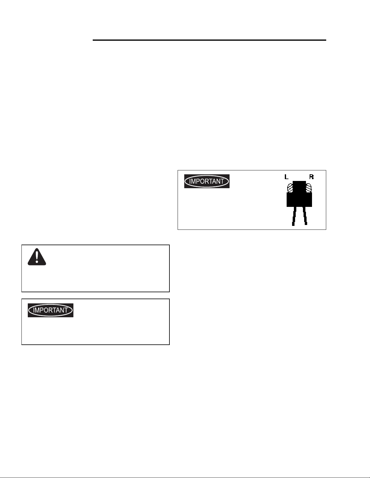
The right and left sides of your
rototiller are determined from the
operating position as you face the
direction of forward trav el.
PREPARATIONPREPARATION
PREPARATION
PREPARATIONPREPARATION
TT
ANT SAFETY ANT SAFETY
T
ANT SAFETY
TT
ANT SAFETY ANT SAFETY
Y READ Y READ
Y READ
Y READ Y READ
W W
ALL INSTRALL INSTR
W
ALL INSTR
W W
ALL INSTRALL INSTR
THIS MANUTHIS MANU
THIS MANU
THIS MANUTHIS MANU
UCTIONSUCTIONS
UCTIONS
UCTIONSUCTIONS
INSTRINSTR
INSTR
INSTRINSTR
AL ANDAL AND
AL AND
AL ANDAL AND
..
.
..
UCTIONSUCTIONS
UCTIONS
UCTIONSUCTIONS
Indicates a situation which maIndicates a situation which ma
Indicates a situation which ma
Indicates a situation which maIndicates a situation which ma
injurinjur
yy
..
It means - attention! Become aler It means - attention! Become aler
injur
y
.
It means - attention! Become aler
injurinjur
yy
..
It means - attention! Become aler It means - attention! Become aler
safsaf
ety is inety is in
saf
ety is in
safsaf
ety is inety is in
ProPro
vides helpful infvides helpful inf
Pro
vides helpful inf
ProPro
vides helpful infvides helpful inf
assembassemb
assemb
assembassemb
rototillerrototiller
rototiller
rototillerrototiller
Please read this section carefullyPlease read this section carefully
Please read this section carefully
Please read this section carefullyPlease read this section carefully
according to the safety instructions and recommendations
outlined here and inserted throughout the text. Mak e
sure anyone who uses the tiller has read the
instructions and is familiar with the controls.
lyly
, oper, oper
ly
, oper
lyly
, oper, oper
..
.
..
vv
olvolv
ed.ed.
v
olv
ed.
vv
olvolv
ed.ed.
oror
mation fmation f
or
mation f
oror
mation fmation f
ation, or maintenance of yation, or maintenance of y
ation, or maintenance of y
ation, or maintenance of yation, or maintenance of y
y cause personaly cause personal
y cause personal
y cause personaly cause personal
t! t!
YY
ourour
t!
Y
our
t! t!
YY
ourour
or properor proper
or proper
or properor proper
ourour
our
ourour
..
. Operate the tiller
..
• Dress appropriately when operating the tiller. Always
wear sturdy footwear. Never wear sandals ,
sneakers, or open shoes, and ne v er oper ate the
tiller with bare feet. Do not w ear loose clothing that
might get caught in moving parts.
• Carefully inspect the area to be tilled, and remove
all foreign objects. Do not till above underground
water lines, gas lines, electric cables , or pipes . Do
not operate the tiller in soil with large rocks and
foreign objects which can damage the equipment.
• Disengage all clutches and shift into neutral before
starting the engine.
• Handle fuel with care; it is highly flammab le.
a. Use an approved fuel container.
b. Never add fuel to a running engine or hot engine.
c. Fill fuel tank outdoors with extreme care. Ne v er fill
fuel tank indoors.
d. Replace gasoline cap securely and clean up
spilled fuel before restarting.
• Never attempt to mak e any adjustments while the
engine is running.
Page 2
Page 7

Operation Safety
OPERAOPERA
OPERA
OPERAOPERA
• Never oper ate the tiller without guards, covers, and
• Never start the engine or operate the tiller with the
• Keep hands, f eet, and clothing a w a y from rotating
• Tines and wheels rotate when tiller is engaged in
• Be extremely cautious when operating in
• Exercise e xtreme caution when operating on or
• After striking a foreign object, stop the engine,
TIONTION
TION
TIONTION
hoods in place.
wheels in the free-wheel position. Mak e sure the
wheel lockouts or lockpins are engaged through
wheel hubs and wheel axle. The wheels act as a
brake to keep the tiller at a controlled speed.
Disengage wheels to permit free-wheeling only when
engine is stopped.
parts. Keep clear of tiller tines at all times .
ff
orworw
ardard
rere
vv
f
orw
ard
ff
orworw
ardard
rotate when the drive safety control levers are pulled
down; in
reverse handle is pulled bac k towards the oper ator.
Releasing the drive safety control le v ers to
stops the wheels and tines.
Take extra care to avoid slipping or falling, and to
keep feet clear of tines.
crossing gravel drives , walks, or roads. Stay alert f or
hidden hazards or traffic.
remove the wire from the spark plug, thoroughly
inspect the tiller for any damage, and repair the
damage before restarting and operating the tiller.
or
rere
re
rere
re
rere
vv
erseerse
v
erse
vv
erseerse
erseerse
v
erse
vv
erseerse
ff
orworw
f
orw
ff
orworw
ardard
ard
, tines and wheels
ardard
neutrneutr
neutr
neutrneutr
rere
re
rere
vv
erseerse
v
erse
vv
erseerse
alal
al
alal
.
-- in
, wheels and tines rotate when the
• Never allo w b ystanders near the unit.
• Use only attachments and accessories approved by
the manufacturer of the tiller .
• Never oper ate the tiller without good visibility or
light.
• Be careful when tilling in hard ground. The tines may
catch in the ground and propel the tiller forward. If
this occurs, let go of the handlebars and do not
restrain the machine.
• Take all possible precautions when leaving the
machine unattended. Disengage all controls le v ers,
stop the engine, wait for all mo ving parts to stop,
and make certain guards and shields are in place.
• When leaving the operating position for an y reason:
- shut off the engine.
- wait for all moving parts to stop.
MAINTENANCE AND STORAGEMAINTENANCE AND STORAGE
MAINTENANCE AND STORAGE
MAINTENANCE AND STORAGEMAINTENANCE AND STORAGE
• Keep machine, attachments , and accessories in
safe working condition.
• Check shear bolts, engine mounting bolts, and other
bolts at frequent intervals for proper tightness to be
sure the equipment is in safe working condition.
• To prevent accidental starting, always disconnect
and secure the spark plug wire from the spark plug
before perf orming tiller maintenance.
• Never run the engine indoors. Exhaust fumes are
deadly.
• If vegetation clogs the tines, raise the handlebars to
rere
vv
elevate the tines , and run the tiller in
does not clean clogged vegetation from the tines,
STST
OP OP
ST
STST
SPSP
SP
SPSP
by hand.
• Engine muffler will be hot from operation. Do not
touch it with bare skin or a severe burn may result.
• If the unit should start to vibrate abnormally, stop
the engine and check immediately for the cause.
Vibration is generally a warning of trouble.
• Do not run the engine indoors; e xhaust fumes are
dangerous.
• Do not overload the machine capacity by attempting
to till too deep at too fast a rate.
• Never oper ate the machine at high transport speeds
on slippery surfaces. Look behind and use care
when backing.
THE ENGINE AND DISCONNECT THE ENGINE AND DISCONNECT
OP
THE ENGINE AND DISCONNECT
OP OP
THE ENGINE AND DISCONNECT THE ENGINE AND DISCONNECT
ARK PLUG ARK PLUG
ARK PLUG
ARK PLUG ARK PLUG
WIRE WIRE
WIRE be fore removing vegetation
WIRE WIRE
re
rere
erseerse
v
erse
vv
erseerse
. If this
THETHE
THE
THETHE
• Always allow m uffler to cool bef ore filling fuel tank.
• Never store equipment with gasoline in the tank
inside a closed building where fumes may reach an
open flame or spark. Allow the engine to cool before
storing in any building.
• Always ref er to the operator's guide instructions f or
important details if the tiller is to be stored for an
extended period.
Page 3
Page 8
Safety Signs & Decals
SAFETY DECALSSAFETY DECALS
SAFETY DECALS
SAFETY DECALSSAFETY DECALS
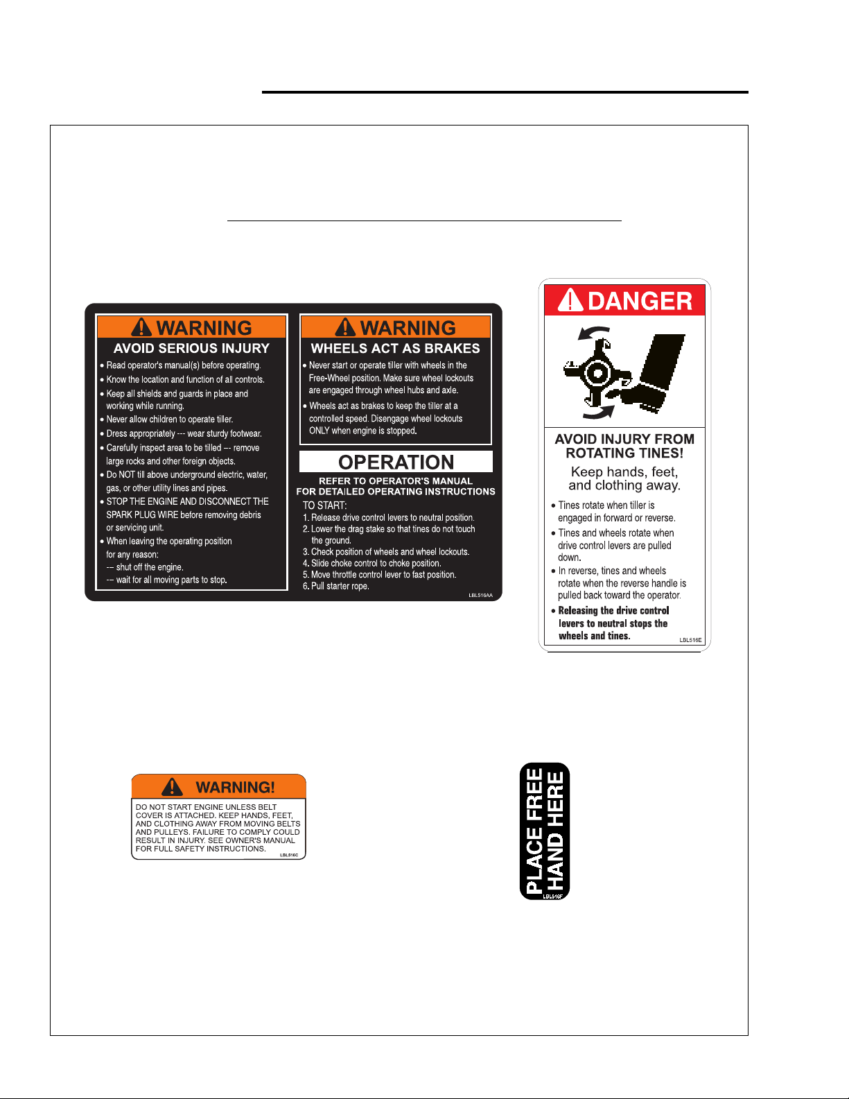
Safety warning decals are placed at strategic locations on the equipment as a constant reminder to the operator
of the most important precautions. All warning, caution and instructional messages on your equipment should be
carefully read and obeyed. If any of these decals are lost or damaged, replace them at once. The y can be
purchased from your local dealer .
OPERAOPERA
OPERA
OPERAOPERA
WW
ARNING / Belt CoARNING / Belt Co
W
ARNING / Belt Co
WW
ARNING / Belt CoARNING / Belt Co
PP
arar
t Not No
P
ar
t No
PP
arar
t Not No
TING INSTRTING INSTR
TING INSTR
TING INSTRTING INSTR
..
1716800 1716800
.
1716800
..
1716800 1716800
PP
arar
P
ar
PP
arar
t Not No
..
1716747 1716747
t No
.
1716747
t Not No
..
1716747 1716747
UCTIONSUCTIONS
UCTIONS
UCTIONSUCTIONS
vv
er Decaler Decal
v
er Decal
vv
er Decaler Decal
/ Hood Decal / Hood Decal
/ Hood Decal
/ Hood Decal / Hood Decal
PP
arar
t Not No
..
t No
t Not No
1716840 1716840
.
1716840
..
1716840 1716840
P
ar
PP
arar
TINES DTINES D
TINES D
TINES DTINES D
PP
arar
t Not No
P
ar
t No
PP
arar
t Not No
FREE HAND / Bumper Guard DecalFREE HAND / Bumper Guard Decal
FREE HAND / Bumper Guard Decal
FREE HAND / Bumper Guard DecalFREE HAND / Bumper Guard Decal
ANGER / Hood Flap DecalANGER / Hood Flap Decal
ANGER / Hood Flap Decal
ANGER / Hood Flap DecalANGER / Hood Flap Decal
..
1716839 1716839
.
1716839
..
1716839 1716839
Page 4
Page 9
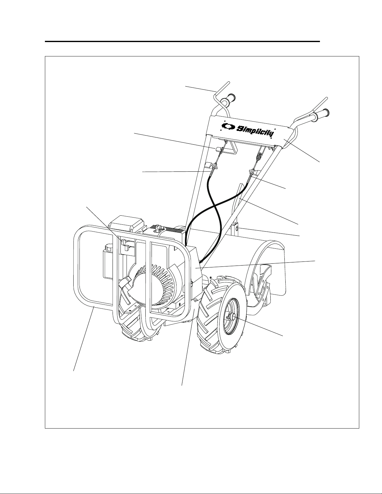
Features
MODEL 6516RMODEL 6516R
MODEL 6516R
MODEL 6516RMODEL 6516R
Reverse Handle
Reverse Belt Tension
Adjustment
Engine Controls
TB*TB*
TB*
TB*TB*
Drive Safety Control Lever
Console
Forward Belt Tension
Adjustment
Drag Stake
Detent Pin
Bumper Guard
(Standard on Model 6516RTB)
Belt Cover
Wheel Lockouts
(Standard on Model 6516RTB)
Serial No. Plate
* Hiller-Furrower Attachment
is standard on Model 6516RTB.
Page 5
Page 10

Controls
SECTION CHECKLISTSECTION CHECKLIST
SECTION CHECKLIST
SECTION CHECKLISTSECTION CHECKLIST
Drive Safety Control Levers
Reverse Handle
Engine Controls
DRIVE SAFETY CONTRDRIVE SAFETY CONTR
DRIVE SAFETY CONTR
DRIVE SAFETY CONTRDRIVE SAFETY CONTR
Engage wheels and tines into forward, releasing returns
machine to neutral.
Pulling down on drive safety control levers engages the
wheels and tines. Releasing drive saf ety control levers
disengages the wheels and brings the tiller to a
complete stop. It is now in the neutral position.
Drive Safety Control
Levers Engaged
OL LEVERSOL LEVERS
OL LEVERS
OL LEVERSOL LEVERS
CAUTION
This information is provided here only to introduce
the controls. DO NO T START THE ENGINE AT THIS
TIME. Starting and operating instructions are given
on page 13. Please read this section and all operating
and safety instructions before starting your tiller .
CAUTION
ENGINE SHOULD BE OFF BEFORE ADJUSTING
ANY CONTROLS!
❖ As a safety precaution, the drive saf ety control
levers will not loc k in the forward position.
❖ To stop the wheels and tines at any time release
the drive safety control le v ers .
Page 6
Page 11

REVERSE HANDLEREVERSE HANDLE
REVERSE HANDLE
REVERSE HANDLEREVERSE HANDLE
Engages wheels and tines in reverse.
Pulling reverse handle bac k to wards oper ator re v erses
tiller.
reverse handle
Controls
CAUTION
Extreme caution should be used when operating
rototiller in the reverse direction.
❖ As a safety precaution, the rev erse handle will
not lock in rev erse .
❖ To stop the wheels and tines at any time,
release the rev erse handle.
❖ Do not operate both the rev erse handle and
drive safety control le v ers at the same time.
Page 7
Page 12

Controls
ENGINE CONTRENGINE CONTR
ENGINE CONTR
ENGINE CONTRENGINE CONTR
OLSOLS
OLS
OLSOLS
Throttle ControlThrottle Control
Throttle Control
Throttle ControlThrottle Control
Move throttle control to f ast position to start and run the
engine. To stop the engine , mo ve to idle position, then to
off.
ChokChok
e Controle Control
Chok
e Control
ChokChok
e Controle Control
Put choke control in choke position if engine is cold. A
warm engine requires less choking than a cold engine.
Refer to your engine manual f or further information.
Briggs & Stratton Intec Engine
Briggs & Stratton Intec Engine
Model 6516RModel 6516R
Model 6516R
Model 6516RModel 6516R
1.Spark plug wire
2.Air cleaner
3. Choke
4.Carburetor
5. Fuel shut-off valve (if equipped)
6.Rope handle
7.Finger guard
8.Stop switch (if equipped)
9.Fuel fill
10.Fuel tank
11.Oil fill/Dipstick (if equipped)
12.Blower housing
13.Oil drain plug
14.Oil fill cap
15.Engine Id plate
16.Muffler
TB &5516RTB &5516R
TB &5516R
TB &5516RTB &5516R
TBTB
TB
TBTB
Page 8
Page 13

Adjustments
SECTION CHECKLISTSECTION CHECKLIST
SECTION CHECKLIST
SECTION CHECKLISTSECTION CHECKLIST
Wheel Lockouts
Handlebar Height Adjustment
Depth Regulator Lever
Belt T ension Adjustment
WHEEL LOCKWHEEL LOCK
WHEEL LOCK
WHEEL LOCKWHEEL LOCK
Place wheels in tilling position.
1. Pull knob in center of wheel out, away from machine.
2. Rotate knob and lockout to align with slot on axle,
release knob. Rotate wheel to align slot in wheel hub
with lockout.
3. Wheel and axle should be firmly lock ed together
before tilling.
4. Repeat for other wheel.
OUTS (6516ROUTS (6516R
OUTS (6516R
OUTS (6516ROUTS (6516R
TB)TB)
TB)
TB)TB)
Model
6516RTB
(6.5-hp)
WHEEL LOCKWHEEL LOCK
WHEEL LOCK
WHEEL LOCKWHEEL LOCK
Place wheels in tilling position.
1. Remove lockpin. Align hole in axle with hole in wheel
hub.
2. Insert lockpin through holes, f old loc kpin ring to
secure pin to axle.
3. Wheel and axle should be firmly lock ed together
before tilling.
4. Repeat for other wheel.
OUTS (5516ROUTS (5516R
OUTS (5516R
OUTS (5516ROUTS (5516R
TB)TB)
TB)
TB)TB)
Model
5516RTB
(5.5-hp)
Wheel lockpin in free-wheel position.
(axle hole only)
Wheel lockout in tilling position.
(hub & axle slot)
NONO
TE:TE:
Alw Alw
aa
ys hays ha
vv
NO
TE:
Alw
a
NONO
TE:TE:
Do not operDo not oper
Do not oper
Do not operDo not oper
To place wheels in free-wheel position.
1. Pull knob in center of wheel out, away from machine.
2. Rotate knob and lockout to align lockout with detent
in end of axle. Release knob .
3. Wheel should turn freely on axle.
ys ha
Alw Alw
aa
ys hays ha
ate tiller with only one wheel locate tiller with only one wheel loc
ate tiller with only one wheel loc
ate tiller with only one wheel locate tiller with only one wheel loc
e both wheel loce both wheel loc
v
e both wheel loc
vv
e both wheel loce both wheel loc
kk
outs in or out.outs in or out.
k
outs in or out.
kk
outs in or out.outs in or out.
kk
ed.ed.
k
ed.
kk
ed.ed.
NONO
TE:TE:
Alw Alw
aa
ys hays ha
vv
NO
TE:
Alw
a
NONO
TE:TE:
Do not operDo not oper
Do not oper
Do not operDo not oper
To place wheels in free-wheel position.
1. Remove lockpin. Slide wheel inw ard tow ard machine .
2. Insert pin in axle only.
3. Wheel should turn freely on axle.
ys ha
Alw Alw
aa
ate tiller with only one wheel locate tiller with only one wheel loc
ate tiller with only one wheel loc
ate tiller with only one wheel locate tiller with only one wheel loc
e both wheel loce both wheel loc
v
e both wheel loc
ys hays ha
vv
e both wheel loce both wheel loc
kk
outs in or out.outs in or out.
k
outs in or out.
kk
outs in or out.outs in or out.
kk
ed.ed.
k
ed.
kk
ed.ed.
CAUTION
Never start engine or operate tiller with wheels in freewheel position. The free-wheel position is for
transporting the tiller long distances over level g round-
-do not attempt to move the tiller up or down steep
grades in the free-wheel position.
Page 9
Page 14

Adjustments
HANDLEBAR HEIGHT ADJUSTMENTHANDLEBAR HEIGHT ADJUSTMENT
HANDLEBAR HEIGHT ADJUSTMENT
HANDLEBAR HEIGHT ADJUSTMENTHANDLEBAR HEIGHT ADJUSTMENT
Adjust handlebar height.
The ideal height of the handlebar varies with operator
height and the depth of tilling. T o adjust handlebar
height:
lock nuts
1. Unscrew nuts and remove top bolt on each side until
handlebar moves freely up and down.
2. Align handlebar to desired hole on the transmission
cover.
3. Install bolts and nuts. Retighten.
height
adjustment
bolts
height
adjustment
bolts
height
adjustment
holes
transmission
cover
3 HANDLEBAR HEIGHT SETTINGS
Page 10
Page 15

Adjustments
DEPTH REGULADEPTH REGULA
DEPTH REGULA
DEPTH REGULADEPTH REGULA
Tilling depth is controlled by the height of the depth
regualtor lever .
To adjust tilling depth.
1. Remove detent pin.
2. Raise the depth regulator lever to position tines at
chosen tilling depth.
3. Align hole in depth regulator le v er with hole in depth
regulator bracket and replace detent pin.
detent pin
depth regulator
bracket
TT
OR LEVEROR LEVER
T
OR LEVER
TT
OR LEVEROR LEVER
depth regulator lever
CAUTION
Always set the depth regulator lever in the transport
position before starting engine, that is, place the detent
pin in the highest hole of the depth regulator lever.
CAUTION
Do not adjust tilling depth unless drive safety control
levers are released to neutr al position.
Depth Regulator LeDepth Regulator Le
Depth Regulator Le
Depth Regulator LeDepth Regulator Le
the detent pin in the top hole of the depth regulator lever
for shallowest tilling.
Depth Regulator LeDepth Regulator Le
Depth Regulator Le
Depth Regulator LeDepth Regulator Le
detent pin in the bottom hole of the depth regulator lever
for deepest tilling.
vv
er Doer Do
v
er Do
vv
er Doer Do
vv
er Up = er Up =
v
er Up =
vv
er Up = er Up =
wn =wn =
wn =
Shallower tilling. Place
wn =wn =
Deeper tilling. Place the
Page 11
Page 16

Adjustments
BELBEL
T T
BEL
BELBEL
Proper belt tension is critical to good performance. After
1/2 hour of operation, all cables may ha v e to be
adjusted due to initial stretch. Thereafter, check tension
after every 2 hours of operation.
TT
o increase belt tension:o increase belt tension:
T
o increase belt tension:
TT
o increase belt tension:o increase belt tension:
1. Loosen upper jam nut. Turn nut up cable in 1/8"
2. Tighten lower jam nut.
TENSION ADJUSTMENTTENSION ADJUSTMENT
T
TENSION ADJUSTMENT
T T
TENSION ADJUSTMENTTENSION ADJUSTMENT
increments.
➜➜
➜➜
➜
upper
jam nut
3. Check adjustment.
This procedure can be repeated until conduit
adjustment bolts have no more adjustment left. If no
more adjustment can be made, belt may ha v e to be
replaced.
bracket
reverse cable
up cable
lower jam nut
forward cable
Page 12
Page 17

SECTION CHECKLISTSECTION CHECKLIST
SECTION CHECKLIST
SECTION CHECKLISTSECTION CHECKLIST
Pre-Start Inspection
Starting and Stopping the Engine
Tilling
Operation
CAUTION
Always put the depth regulator lever in the transport
position before starting engine. Tines should clear the
ground.
PRE-STPRE-ST
PRE-ST
PRE-STPRE-ST
1. Make sure all safety guards are in place and all nuts
and bolts are secure.
2. Check oil level in engine crankcase. See y our engine
manual for procedure and specifications.
3. Inspect air cleaner for cleanliness. See your engine
manual for procedure.
4. Check the fuel supply. Fill the fuel tank no closer
than 1 inch from top of tank to provide space for
expansion. See y our engine man ual for fuel
recommendations.
5. Be sure spark plug wire is attached and spark plug is
tightened securely .
6. Check position of wheels and wheel lockouts.
7. Check depth regulator lever position.
ARAR
T INSPECTIONT INSPECTION
AR
T INSPECTION
ARAR
T INSPECTIONT INSPECTION
CAUTION
Please do not start your tiller until you have read the
Manual that came with your engine, and the sections
in this manual titled Controls, Adjustments and Safety.
If you hav e read these, follow the steps belo w to start
your tiller. Always perform this pre-start checklist
before starting the engine.
ENGINE IS SHIPPED FRENGINE IS SHIPPED FR
ENGINE IS SHIPPED FR
ENGINE IS SHIPPED FRENGINE IS SHIPPED FR
WITHOUT OIL.WITHOUT OIL.
WITHOUT OIL.
WITHOUT OIL.WITHOUT OIL.
BEFORE STBEFORE ST
BEFORE ST
BEFORE STBEFORE ST
STST
ARAR
ST
STST
ENGINEENGINE
ENGINE
ENGINEENGINE
NONO
NO
NONO
instrinstr
instr
instrinstr
TING AND STTING AND ST
AR
TING AND ST
ARAR
TING AND STTING AND ST
TE:TE:
Ref Ref
TE:
Ref
TE:TE:
Ref Ref
uctionsuctions
uctions
uctionsuctions
YY
OO
U MUST ADD ENGINE OILU MUST ADD ENGINE OIL
Y
O
U MUST ADD ENGINE OIL
YY
OO
U MUST ADD ENGINE OILU MUST ADD ENGINE OIL
ARAR
TING ENGINE.TING ENGINE.
AR
TING ENGINE.
ARAR
TING ENGINE.TING ENGINE.
er to engine maner to engine man
er to engine man
er to engine maner to engine man
..
.
..
OM FOM F
AA
CTCT
OM F
OM FOM F
OPPING OPPING
OPPING
OPPING OPPING
ual fual f
ual f
ual fual f
OROR
A
CT
OR
AA
CTCT
OROR
or proper operor proper oper
or proper oper
or proper operor proper oper
YY
Y
YY
THETHE
THE
THETHE
CAUTION
Always keep hands and f eet clear of rotating machine
parts.
CAUTION
T emperature of muffler and near b y areas may exceed
150° F. A v oid these areas .
atingating
ating
atingating
CAUTION
Gasoline is highly flammable and must be handled
with care. Never fill the tank when the engine is hot or
running. Always move outdoors to fill the tank.
CAUTION
Wheels must always be loc ked in the TILLING position
when engine is running. Do not operate the tiller with
the wheel lockouts unlocked. Always set the wheels
in tilling position before starting engine.
CAUTION
Do not move choke control to CHOKE to stop engine .
Backfire or engine damage may occur.
To stop the engine at any time, move throttle control
to the off position. To stop wheels and tines at an y
time, release drive safety control le v ers to neutral
position.
Page 13
Page 18

Operation
TILLINGTILLING
TILLING
TILLINGTILLING
1. Adjust the depth regulator lever to desired tilling
depth.
NONO
TE:TE:
NO
NONO
timetime
time
timetime
depth regulator ledepth regulator le
depth regulator le
depth regulator ledepth regulator le
control of control of
control of
control of control of
2. Move the throttle control to
3. Place the tiller in
NONO
NO
NONO
anan
an
anan
handlebarshandlebars
handlebars
handlebarshandlebars
the drthe dr
the dr
the drthe dr
Raise depth regulator leRaise depth regulator le
TE:
Raise depth regulator le
TE:TE:
Raise depth regulator leRaise depth regulator le
, testing tiller oper, testing tiller oper
, testing tiller oper
, testing tiller oper, testing tiller oper
tiller!tiller!
tiller!
tiller!tiller!
drive safety control le v ers--this will engage the
wheels and tines.
TE:TE:
YY
ou can sloou can slo
TE:
Y
ou can slo
TE:TE:
YY
ou can sloou can slo
y time by time b
y time b
y time by time b
y putting slight doy putting slight do
y putting slight do
y putting slight doy putting slight do
, or y, or y
, or y
, or y, or y
iviv
e safe saf
iv
iviv
ety control leety control le
e saf
ety control le
e safe saf
ety control leety control le
ation after each ration after each r
ation after each r
ation after each ration after each r
vv
er too high can result in loss ofer too high can result in loss of
v
er too high can result in loss of
vv
er too high can result in loss ofer too high can result in loss of
ff
orworw
ardard
f
orw
ard
ff
orworw
ardard
w the tiller's fw the tiller's f
w the tiller's f
w the tiller's fw the tiller's f
ou can stop the tiller bou can stop the tiller b
ou can stop the tiller b
ou can stop the tiller bou can stop the tiller b
vv
v
vv
vv
er up one hole at aer up one hole at a
v
er up one hole at a
vv
er up one hole at aer up one hole at a
aiseaise
..
Raising Raising
aise
.
Raising
aiseaise
..
Raising Raising
ff
astast
f
ast
.
ff
astast
by pushing down on the
orworw
ard advard adv
orw
ard adv
orworw
ard advard adv
wnwwnw
ard pressure on theard pressure on the
wnw
ard pressure on the
wnwwnw
ard pressure on theard pressure on the
ers to the neutrers to the neutr
ers to the neutr
ers to the neutrers to the neutr
ance atance at
ance at
ance atance at
y releasingy releasing
y releasing
y releasingy releasing
al position.al position.
al position.
al position.al position.
CAUTION
To stop wheels and tines at any time, release drive
safety control lev ers to neutral position.
CAUTION
Always release drive safety control levers to neutral
position before adjusting the depth regulator lev er .
Practice operating the controls and tiller with tines out
of ground before beginning to till. It is important that
you know how to use the tiller properly, how to keep
control at all times, how to stop the tines and wheels
from turning, and how to stop the engine if necessary.
If you do not know how to do these things, read the
Controls, Adjustments and Safety sections before
proceeding.
Page 14
Page 19

Tips
TILLING TILLING
TILLING
TILLING TILLING
The key to successful tilling is to begin with a shallow
cut on the first pass, and then work an inch or two
deeper on each successive pass.
✮ Tilling depth will v ary with ground conditions.
✮ When beginning to till in unbroken ground or in
extremely hard soil, set the detent pin in the highest
hole of the drag stake (follow instructions under
Tilling on previous page). This will allow for shallow
tilling. With the dr ag stake in this position, mak e
several light passes o v er the area to be tilled. Reset
for deeper depths with successive passes.
✮ If tiller jumps or skids uncontrollably, lower the drag
stake by placing the detent pin in a higher hole. This
will allow for shallower tilling. Hold firmly to the
handlebars to control sudden lurches.
✮ If weeds, tall g rasses, vines , or other materials clog
or jam the tines, rev erse the tiller to unwind
vegetation.
Immediately release the drive control lev ers if the tines
jam or you strike a foreign object. With drive control
levers in neutr al, push throttle control to
stop the engine. Disengage the spark plug wire. When
tines have stopped, remo ve foreign objects and check
for damage.
TIPSTIPS
TIPS
TIPSTIPS
stopstop
stop position to
stopstop
CAUTION
Extreme caution must be taken in selecting tilling
depth. If y ou attempt to till too deeply for soil conditions,
that is, with the drag stake in too high a position, loss
of control could result.
CAUTION
If removing material from the tines by hand, stop
engine and remove spark plug wire first.
CULCUL
TIVTIV
AA
CUL
TIV
CULCUL
TIVTIV
If you plan to use your tiller for cultiv ating:
✮ Plant rows on 20" - 22" centers f or ease of turning.
✮ Set the drag stak e with the detent pin in one of the
higher holes. This will allow the shallow cultivation
necessary to turn over weeds, and break up and
aerate the soil.
TING TING
A
TING
AA
TING TING
TIPSTIPS
TIPS
TIPSTIPS
Page 15
Page 20

Maintenance and Storage
SECTION CHECKLISTSECTION CHECKLIST
SECTION CHECKLIST
SECTION CHECKLISTSECTION CHECKLIST
Check Forward Belt T ension
Check Rev erse Belt T ension
Change Forward/Re verse Belt
Check or Fill Engine Crankcase
CAUTION
To prevent accidental starting:
Check Tiller T r ansmission Grease
Check Tire Pressure
Lubrication
Clean Tine Axle Shaft
Engine Maintenance
Prepare for Storage
Tiller and Engine Maintenance Schedule
CHECK FORCHECK FOR
CHECK FOR
CHECK FORCHECK FOR
Forward belt tension ma y decrease over time. It must be
adjusted within the first half hour of operation, and
checked after e v ery two hours of operation. Proper
adjustment will assure long belt life. Too much or too
little belt tension will cause premature belt failure. To
check and adjust the forward belt tension:
1. Turn off engine. Engine must be cool.
2. Remove and secure spark plug wire from spark plug.
3. With driv e saf ety control le v ers in neutr al position,
measure length of spring when compressed.
WW
ARD BELARD BEL
W
ARD BEL
WW
ARD BELARD BEL
T T
TENSIONTENSION
T
TENSION
T T
TENSIONTENSION
Engine must be turned off and cool, and spark plug
wire must be removed and secured from spark plug
before checking and adjusting engine or equipment.
1"
1-1/4"
4. Pull down on driv e safety control levers and
remeasure length of spring when stretched out. Ideal
length would be 1/4" longer.
CHECK REVERSE BELCHECK REVERSE BEL
CHECK REVERSE BEL
CHECK REVERSE BELCHECK REVERSE BEL
Reverse belt tension is not adjustab le.
T T
TENSIONTENSION
T
TENSION
T T
TENSIONTENSION
CAUTION
Check forward belt tension regularly . Too much or too
little tension will cause premature belt failure.
Page 16
Page 21

Maintenance and Storage
CHANGE FORCHANGE FOR
CHANGE FOR
CHANGE FORCHANGE FOR
BELBEL
TT
BEL
T
BELBEL
TT
1. Turn off engine. Engine must be cool.
2. Remove spark plug wire and secure from spark plug.
3. Remove belt guard.
✮ remove the forw ard belt from the f orward engine
pulley:
- gently pull the engine recoil rope to rotate the
pulley.
- with the pulley turning, force the forward belt
out of the V-groove.
- slide the belt free of the engine pulley.
- pull the forward belt down and out of the w a y.
✮ remove the rev erse belt from the reverse engine
pulley:
- gently pull the engine recoil rope to rotate the
pulley.
- with the pulley turning, force the rev erse belt
out of the V-groove.
- slide the belt free of engine pulleys and rev erse
belt guides.
- pull belt down and awa y from transmission
pulley.
WW
ARD/REVERSEARD/REVERSE
W
ARD/REVERSE
WW
ARD/REVERSEARD/REVERSE
✮ install new reverse belt:
- thread belt up from bottom.
- place belt around transmission pulley in groov e .
- place belt under reverse belt guides .
- gently pull engine recoil rope while forcing the
belt over the edge of the engine pulle y into the
V -g roov e .
✮ install new forward belt:
- place forward belt in transmission pulle y
groove .
- gently pull the engine recoil rope to rotate the
pulley while forcing the f orward belt into the
V -g roov e .
4. Replace belt guard.
5. Attach spark plug wire .
Page 17
Page 22

Maintenance and Storage
CHECK OR FILL ENGINECHECK OR FILL ENGINE
CHECK OR FILL ENGINE
CHECK OR FILL ENGINECHECK OR FILL ENGINE
CRANKCASECRANKCASE
CRANKCASE
CRANKCASECRANKCASE
1. Add oil according to chart below .
Use a high quality detergent oil classified "For
Service SF-SJ,". Use no special additiv es with
recommended oils. Do not mix oil with gasoline.
2. Alw a ys chec k oil le v el before starting engine. Ref er
to engine manual for complete instructions.
Do not oDo not o
Do not o
Do not oDo not o
vv
erfill.erfill.
v
erfill.
vv
erfill.erfill.
Engine is shipped from fEngine is shipped from f
Engine is shipped from f
Engine is shipped from fEngine is shipped from f
mm
ust add engine oil befust add engine oil bef
m
ust add engine oil bef
mm
ust add engine oil befust add engine oil bef
Adapted from Briggs & Stratton Corporation, Form No. 274263-10/99.
*
Air cooled engines run hotter than automotive engines. Use
of non-synthetic multi-viscosity oils (5W30, 10W-30, etc.)
above 40ο F (4ο C) will result in high oil consumption and
possible engine damage. Check oil level more frequently if
using these types of oils.
**
SAE 30 oil, if used below 40
starting and possible engine bore damage due to inadequate
lubrication.
actoractor
y without oil.y without oil.
actor
y without oil.
actoractor
y without oil.y without oil.
ore starore star
ore star
ore starore star
ο
ting engineting engine
ting engine
ting engineting engine
ο
F (4
C), will result in hard
YY
ouou
Y
ou
YY
ouou
..
.
..
Adapted from Briggs & Stratton Corporation, Form No. 274263-10/99.
Page 18
Page 23

Maintenance and Storage
CHECK CHECK
CHECK
CHECK CHECK
GREASEGREASE
GREASE
GREASEGREASE
TILLER TILLER
TILLER
TILLER TILLER
FF
AA
CTCT
F
A
CT
FF
AA
CTCT
00 LIQ00 LIQ
00 LIQ
00 LIQ00 LIQ
Check the grease lev el ann ually. To chec k the grease
level:
1. Move tiller to level ground.
2. Remove grease level dipstick located betw een the
handlebar mounts in the front transmission cover.
Correct 00 grease lev el is indicated betw een the high
and low lev els on the dipstick.
3. Replace grease level dipstick in the filler hole.
4. Note that the front wheel transmission and rear tine
transmission are one common reservoir. When you
add to the front transmission, you must wait a short
period of time for the 00 grease to flow rearward and
equalize in both front and rear. The dipstick will read
correctly on level g round f or both gear units.
TILLER TILLER
TILLER
TILLER TILLER
TRANSMISSION IS SHIPPED FRTRANSMISSION IS SHIPPED FR
TRANSMISSION IS SHIPPED FR
TRANSMISSION IS SHIPPED FRTRANSMISSION IS SHIPPED FR
OROR
Y Y
WITH WITH
OR
Y
WITH
OROR
Y Y
WITH WITH
UID GREASE.UID GREASE.
UID GREASE.
UID GREASE.UID GREASE.
TRANSMISSIONTRANSMISSION
TRANSMISSION
TRANSMISSIONTRANSMISSION
THE PRTHE PR
THE PR
THE PRTHE PR
OPER AMOUNT OFOPER AMOUNT OF
OPER AMOUNT OF
OPER AMOUNT OFOPER AMOUNT OF
OMOM
OM
OMOM
CHECK CHECK
CHECK
CHECK CHECK
Recommended tire pressure is 20 PSI. If tires do not
have equal pressure, tiller will pull to one side.
LUBRICALUBRICA
LUBRICA
LUBRICALUBRICA
Proper lubrication of moving mechanical parts of your
rototiller is a very important part of care and
maintenance. You should oil the moving parts shown at
10 hour intervals using a 30 weight oil.
CLEAN CLEAN
CLEAN
CLEAN CLEAN
1. Turn off engine. Engine must be cool.
2. Remove spark plug wire and secure from spark plug.
3. Tip the tiller forward. Block the tiller in position so
that it rests on the engine mount and the tines are
exposed.
4. Remove all vegetation, string, wire, and other
material that may have accumulated on the axle
between the inside set of tines and the seal on the
transmission housing.
5. Tip the tiller back to a level position.
6. Replace spark plug wire.
TIRE PRESSURETIRE PRESSURE
TIRE PRESSURE
TIRE PRESSURETIRE PRESSURE
TIONTION
TION
TIONTION
TINE AXLE SHAFTTINE AXLE SHAFT
TINE AXLE SHAFT
TINE AXLE SHAFTTINE AXLE SHAFT
When replacing gWhen replacing g
When replacing g
When replacing gWhen replacing g
holds 18-22 ouncesholds 18-22 ounces
holds 18-22 ounces
holds 18-22 ouncesholds 18-22 ounces
reaserease
rease
reaserease
..
DO NO DO NO
.
DO NO
..
DO NO DO NO
dipstick
transmission
, the tiller tr, the tiller tr
, the tiller tr
, the tiller tr, the tiller tr
T OT O
VERFILL.VERFILL.
T O
VERFILL.
T OT O
VERFILL.VERFILL.
gear case
dipstick hole
cover plate
ansmissionansmission
ansmission
ansmissionansmission
Page 19
Page 24

Maintenance and Storage
ENGINE MAINTENANCEENGINE MAINTENANCE
ENGINE MAINTENANCE
ENGINE MAINTENANCEENGINE MAINTENANCE
Refer to the engine manual included in your parts
packet f or information on engine maintenance. Your
engine manual provides detailed information and a
maintenance schedule for performing the follo wing
tasks:
CAUTION
Do not operate tiller before reading the engine manual
provided in the parts packet.
1. Check oil level before each use or after ev ery 8
hours of operation.
2. Change oil after first 5-8 hours of operation. Change
oil while engine is warm. Refill with new oil of
recommended grade.
4. Check spark plug yearly or every 100 hours of
operation.
5. Service air cleaner .
6. Keep engine and parts clean.
7. Check engine and equipment often for loose nuts
and bolts, keep these items tightened.
CAUTION
T emperature of muffler and near by areas ma y exceed
150° F. Avoid these areas .
Engine can overheat and become damaged if
debris blocks the cooling system or rotating screen.
Never run engine without complete air cleaner
installed on engine.
Page 20
Page 25

Maintenance and Storage
PREPPREP
PREP
PREPPREP
Follow the steps below to prepare y our tiller f or storage .
Read your engine manual for detailed instructions on
preparing the engine for storage.
1. Protect wheels and axles from rust:
2. Run with gas stabilizer in fuel.
3. Drain the fuel tank. Run the engine until it stops.
4. While engine is still warm, drain the oil from the
TILLER AND ENGINE MAINTENANCE SCHEDULETILLER AND ENGINE MAINTENANCE SCHEDULE
TILLER AND ENGINE MAINTENANCE SCHEDULE
TILLER AND ENGINE MAINTENANCE SCHEDULETILLER AND ENGINE MAINTENANCE SCHEDULE
ARE FOR STARE FOR ST
ARE FOR ST
ARE FOR STARE FOR ST
- Loosen locking bolt inside wheel. Slide wheel
toward machine.
- Coat the axles lightly with axle grease.
- Move wheel back into position and snug loc king
bolt. Bac k off loc king bolt 1/16 turn and lock jam
nut.
engine. Refill with fresh oil of the recommended
grade.
ORAORA
ORA
ORAORA
GEGE
GE
GEGE
5. Remove spark plug, pour one-half ounce of clean
engine oil into cylinder. Pull starter handle slowly
sever al times to distribute oil. Replace spark plug.
6. Clean entire tiller.
7. Store your tiller in a clean, dry building.
Do not store tiller in an unventilated area where fuel
fumes may reach flame, sparks, pilot lights or an
ignited object. Drain fuel outdoors away from any
ignition sources. Use only appro v ed fuel containers .
CAUTION
Your tiller will require maintenance including service and adjustments before and after use. T o help ensure long lif e
and peak performance for your tiller, follow the maintenance schedule below. Refer to your Briggs & Stratton
manual to establish a maintenance schedule for the engine .
Maintenance Operation See Page # Before Each Use 50 hrs or
Every Season
Check forward belt tension _________ 16 ___________ ✓
Check or fill engine crankcase ______ 18 ___________ ✓
Check tiller transmission grease _____ 19 ___________ ✓
Check tire pressure _______________ 19 ___________ ✓
Change forward/reverse belt ________ 17 _______________________________ ✓
Clean tine axle shaft ______________ 19 _______________________________ ✓
Lube wheel axle shaft _____________ 21 _______________________________ ✓
Check throttle control adjustment ____ EM_______________________________ 1
Change engine oil ________________ EM_______________________________ 2
EM = See engine manual.
11
1 Adjust throttle control after first 3 hours of operation or if engine is hard to start or run-on occurs.
11
22
2 Change oil after first 5-8 hours of use, then after every 50 hours or every season. Change oil every 25 hours
22
when operating under heavy load or in high temperatures.
Page 21
Page 26

Troubleshooting and Repair
TRTR
OUBLESHOOOUBLESHOO
TR
OUBLESHOO
TRTR
OUBLESHOOOUBLESHOO
Engine will not starEngine will not star
Engine will not star
Engine will not starEngine will not star
TING GUIDETING GUIDE
TING GUIDE
TING GUIDETING GUIDE
PRPR
OBLEMOBLEM
PR
OBLEM
PRPR
OBLEMOBLEM
tt
t
tt
CAUTION
Practice safety at all times. Engine must be turned off
and allowed to cool, and spark plug wire must be
disconnected and secured before attempting any
maintenance or repair.
REMEDREMED
REMED
REMEDREMED
1.Connect spark plug wire to spark plug
2.Throttle must be positioned at choke for a cold start
(see page 8 for instructions)
Y/ACTIONY/ACTION
Y/ACTION
Y/ACTIONY/ACTION
Engine rEngine r
Engine r
Engine rEngine r
Engine is hard to starEngine is hard to star
Engine is hard to star
Engine is hard to starEngine is hard to star
Engine misses or lacEngine misses or lac
Engine misses or lac
Engine misses or lacEngine misses or lac
Engine will not stop when throttle control isEngine will not stop when throttle control is
Engine will not stop when throttle control is
Engine will not stop when throttle control isEngine will not stop when throttle control is
positioned at stoppositioned at stop
positioned at stop
positioned at stoppositioned at stop
Tiller moTiller mo
Tiller mo
Tiller moTiller mo
Tiller is difficult to control when tilling (machine jumpsTiller is difficult to control when tilling (machine jumps
Tiller is difficult to control when tilling (machine jumps
Tiller is difficult to control when tilling (machine jumpsTiller is difficult to control when tilling (machine jumps
or or
or
or or
uns rough, floods duruns rough, floods dur
uns rough, floods dur
uns rough, floods duruns rough, floods dur
vv
es fes f
orworw
v
es f
orw
vv
es fes f
orworw
lurches flurches f
lurches f
lurches flurches f
orworw
orw
orworw
ard)ard)
ard)
ard)ard)
tt
t
tt
ks poks po
ks po
ks poks po
ard durard dur
ard dur
ard durard dur
ing opering oper
ing oper
ing opering oper
ww
erer
w
er
ww
erer
ing staring star
ing star
ing staring star
tingting
ting
tingting
ationation
ation
ationation
1.Clean or replace air cleaner
1.Drain old fuel and replace with fresh. Use gas stabilizer
at end of season
2.Make sure spark plug wire is securely attached to spark
plug
neutrneutr
alal
neutr
3.Drive safety control levers must be released to
to start the engine
1.Raise the tines for shallower tilling by lowering the depth
regulator lever, see page 11
2.Remove and clean fuel tank
3.Clean or replace air cleaner
4.Improper carburetor adjustment, take to authorized
Briggs & Stratton service center
5.Replace spark plug and adjust gap
6.Drain and refill gas tank and carburetor
1.See engine manual to check and adjust throttle linkage
1.Drive safety control levers must be released to
to start the engine
1.Lock wheels in tilling position, see page 9
2.Raise the tines for shallower tilling by lowering the depth
regulator lever, see page 11
neutrneutr
neutrneutr
neutr
neutrneutr
al
alal
al
alal
alal
Tines turTines tur
Tines tur
Tines turTines tur
Tines turTines tur
Tines tur
Tines turTines tur
n, wheels do not turn, wheels do not tur
n, wheels do not tur
n, wheels do not turn, wheels do not tur
n, wheels turn, wheels tur
n, wheels tur
n, wheels turn, wheels tur
n, tiller does not mon, tiller does not mo
n, tiller does not mo
n, tiller does not mon, tiller does not mo
nn
n
nn
vv
ee
v
e
vv
ee
1.Lock wheels in tilling position, see page 9
2.Internal transmission failure, see your dealer
1.Lower the tines for deeper tilling by raising the depth
regulator lever, see page 11
Page 22
Page 27

PRPR
PR
PRPR
Belts squeal in neutrBelts squeal in neutr
Belts squeal in neutr
Belts squeal in neutrBelts squeal in neutr
OBLEMOBLEM
OBLEM
OBLEMOBLEM
al and/or real and/or re
al and/or re
al and/or real and/or re
vv
erseerse
v
erse
vv
erseerse
Troubleshooting and Repair
REMEDREMED
REMED
REMEDREMED
1.Adjust forward belt guide:
- turn engine off and allow muffler to cool
- disconnect spark plug wire and secure from spark plug
- remove belt guard
- pull down on drive safety control levers
- manually bend forward belt guide so there is 1/16
inch or less clearance between belt guide and belt
- replace belt guard and spark plug wire
Y/ACTIONY/ACTION
Y/ACTION
Y/ACTIONY/ACTION
Belts squeal in fBelts squeal in f
Belts squeal in f
Belts squeal in fBelts squeal in f
ExcessivExcessiv
Excessiv
ExcessivExcessiv
durdur
dur
durdur
e heat be heat b
e heat b
e heat be heat b
ing tillinging tilling
ing tilling
ing tillinging tilling
orworw
ard operard oper
orw
ard oper
orworw
ard operard oper
uild up in truild up in tr
uild up in tr
uild up in truild up in tr
ationation
ation
ationation
ansmission/tine areaansmission/tine area
ansmission/tine area
ansmission/tine areaansmission/tine area
1.Adjust tabs on the reverse belt guide
- turn engine off and allow muffler to cool
- disconnect spark plug wire and secure from spark plug
neutrneutr
alal
neutr
- release drive safety control levers to
- remove belt guard
- adjust tabs of reverse belt guide:
while drive safety control levers are released, bend
metal tabs on reverse belt guide to 1/64 inch or less
clearance from reverse belt
- replace belt guard and spark plug wire
1.Remove vegetation by following instructions in Clean
Tine Axle Shaft on page 19 of Maintenance & Storage
section. FOLLOW ALL SAFETY INSTRUCTIONS
2.Check transmission fluid and fill if needed by following
instructions on page 19
neutrneutr
al
alal
Page 23
Page 28

Specifications
FEAFEA
TURESTURES
FEA
TURES
FEAFEA
TURESTURES
N 6.5-HP Briggs & Stratton Engine (6516RTB)
N 5.5-HP Briggs & Stratton Engine (5516RTB)
N Tractor Type Pneumatic Tires
N All Gear Drive Transmission
N Handlebar Height Adjustment
N Forward/Reverse Control
N Functional Depth Regulator System
N Wheel Lockout Control (6516RTB)
N Drive Safety Control Levers
N Self Cleaning Bolo Tines (6516RTB)
N Slasher Tines (5516RTB)
N Bumper Guard (6516RTB)
N Hiller-Furrower Attachment (6516RTB)
TECHNICAL MANUTECHNICAL MANU
TECHNICAL MANU
TECHNICAL MANUTECHNICAL MANU
AA
VV
AILABILITYAILABILITY
A
V
AILABILITY
AA
VV
AILABILITYAILABILITY
Additional copies of this manual, as well as a fully
illustrated Parts Manuals for y our unit are a v ailable . The
Parts Manuals show all of the assemblies and individual
parts as exploded views which show the relationship of
the parts and how they go together. Important assembly
notes and special torque values are included in the
illustrations. Standard hardware and torque specification
charts are also included.
To order copies of the manuals applicable
to your model, contact the Simplicity
Customer Publications Department at
414-284-8519.414-284-8519.
414-284-8519.
414-284-8519.414-284-8519.
Have the follo wing inf ormation on the form
at the right available when phoning in y our request.
ALAL
AL
ALAL
Model: __________________________________________________
M/N (Mfg. No.): ___________________________________________
S/N (Serial #): ____________________________________________
Your Name: ______________________________________________
Address: ________________________________________________
City, State, Zip: ___________________________________________
Visa/Mastercard No.: ______________________________________
Card Expiration Date: ______________________________________
Page 24
 Loading...