

Page 1
Rev. 8/2000
TP 400-2378-00-AT-SMA
Attachment
Illustrated
Parts List
© Copyright 2000 Simplicity Manufacturing, Inc.All Rights Reserved.
MANUFACTURING, INC.
500 N Spring Street / PO Box 997
Port Washington, WI 53074-0997 USA
Page 2
2
TP 400-2378-00-AT-SMA
© Copyright 2000 Simplicity Manufacturing, Inc. All Rights Reserved.
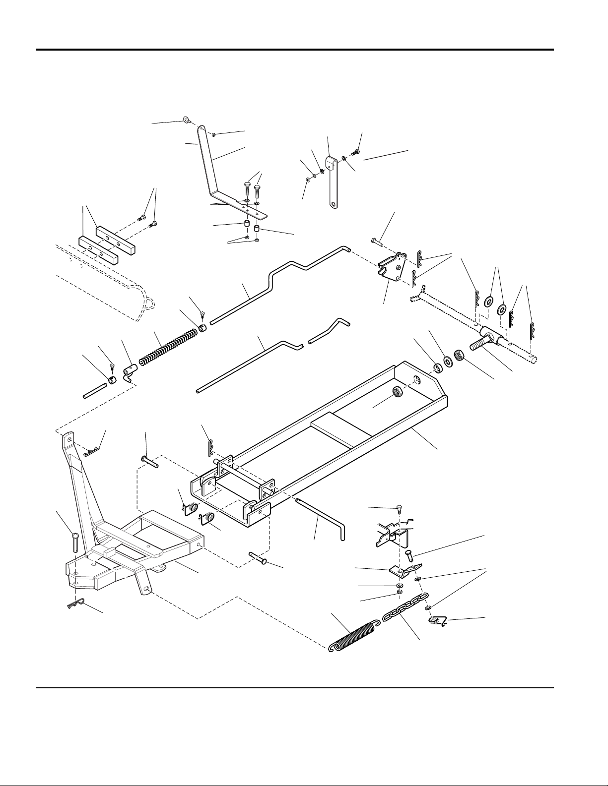
Hitch 42” Blade
NOTE: Unless noted otherwise,
use the standard hardware torque
specification chart.
985751
The above parts group applies to the following Mfg. Nos.:
1693756 Hitch 42” Blade
Manual
Lift
Electric/
Hydraulic
Lift
Top
of RH
Footrest
Replaces #32 when
used snow cabs.
Secure to cross bar
above hood.
2
1
3
5
6
7
8
10
13
17
18
27
29
16
28
27
12
13
14
15
30
9
9
9
11
20
28
22
23
24
25
26
19
21
9
9
4
4
3
33
31
38
38
32
34
35
36
26
25
24
37
25
34
28
Page 3

3
TP 400-2378-00-AT-SMA
Hitch 42” Blade
1 1709813 2 BAR
2 1960373 2 CAPSCREW, Taptite, 5/16-18 x 1
3 1928721 2 SCREW, Set, 5/16-18 x 1/2
4 8031007 2 COLLAR
5 171679 1 GUIDE ASSEMBLY
6 171011 1 SPRING
7 1665887 1 ROD, Manual Lift
8 1707542 1 ROD, Eletric / Hydraulic Lift
9 1960033 7 PIN, Hair
10 1686765 1 EXTENSION ASSEMBLY KIT
11 1911386 2 WASHER, 3/4
12 1720188 1 TUBE & BOLT ASSEMBLY
13 1915726 2 NUT, Hex, 5/8-11
14 1960035 1 WASHER, 5/8
15 175647 1 SPACER
16 1603602 1 PIN
17 1720187 1 REAR PUSH BAR ASSEMBLY
18 1715758 1 ROD
19 1921333 1 CAPSCREW, Hex Head 5/16-18 x 1
20 1655651 1 PIN
21 1919381 2 WASHER, 5/16
22 1708266 1 CHAIN, Link
23 1675232 1 SPRING
24 1917372 1 NUT, Hex, 5/16-18
25 1917356 2 LOCKWASHER, 5/16
26 1704757 1 BRACKET
27 118053 2 PIN
28 176012 4 RETAINER, Pin
29 1721045 1 PUSH BAR ASSEMBLY
30 8181008 1 PIN, Round Head, 1/2 x 2-1/2
31 172162 1 EYEBOLT
32 1721057 1 BRACKET
33 1920397 1 LOCKNUT, Hex, 1/4-20
34 1921221 2 CAPSCREW, Hex Head, 5/16-18 x 1-1/2
35 1919326 2 WASHER, 5/16
36 1923362 2 NUT, Centerlock, 5/16-18
37 1721278 1 BRACKET
38 1705249 2 SPACER
REF NO. PART NO. QTY. DESCRIPTION
Footnotes:
The above parts group applies to the following Mfg. Nos.:
1693756 Hitch 42” Blade
Page 4

Torque Specification Chart
FOR STANDARD MACHINE HARDWARE (Tolerance ± 20%)
Hardware
Grade
SAE Grade 2 SAE Grade 5 SAE Grade 8
Size Of
in/lbs in/lbs
in/lbs
Hardware ft/lbs Nm. ft/lbs Nm. ft/lbs Nm.
8-32
19
2.1
30
3.4
41
4.6
8-36
20
2.3
31
3.5
43
4.9
10-24
27
3.1
43
4.9
60
6.8
10-32
31
3.5
49
5.5
68
7.7
1/4-20
66
7.6 8 10.9 12 16.3
1/4-28
76
8.6 10 13.6 14 19.0
5/16-18 11 15.0 17 23.1 25 34.0
5/16-24 12 16.3 19 25.8 27 34.0
3/8-16 20 27.2 30 40.8 45 61.2
3/8-24 23 31.3 35 47.6 50 68.0
7/16-14 30 40.8 50 68.0 70 95.2
7/16-20 35 47.6 55 74.8 80 108.8
1/2-13 50 68.0 75 102.0 110 149.6
1/2-20 55 74.8 90 122.4 120 163.2
9/16-12 65 88.4 110 149.6 150 204.0
9/16-18 75 102.0 120 163.2 170 231.2
5/8-11 90 122.4 150 204.0 220 299.2
5/8-18 100 136 180 244.8 240 326.4
3/4-10 160 217.6 260 353.6 386 525.0
3/4-16 180 244.8 300 408.0 420 571.2
7/8-9 140 190.4 400 544.0 600 816.0
7/8-14 155 210.8 440 598.4 660 897.6
1-8 220 299.2 580 788.8 900 1,244.0
1-12 240 326.4 640 870.4 1,000 1,360.0
Hex Head Capscrew
Hex Nut
Lockwasher
Washer
Carriage Bolt
NOTES
1. These torque values are to be used for all hardware
excluding: locknuts, self-tapping screws, thread forming
screws, sheet metal screws and socket head setscrews.
2. Recommended seating torque values for locknuts:
a. for prevailing torque locknuts - use 65% of grade 5
torques.
b. for flange whizlock nuts and screws - use 135% of
grade 5 torques.
3. Unless otherwise noted on assembly drawings, all torque
values must meet this specification.
Hardware Identification & Torque Specifications
Common Hardware Types
Screw, 1/2 x 2
Body
Diameter
Body
Length
Inside
Diameter
Nut, 1/2”
No
Marks
3/8” Bolt or Nut
Wrench—9/16”
3/8
5/16” Bolt or Nut
Wrench—1/2”
5/16
1/4” Bolt or Nut
Wrench—7/16”
1/4
1/2” Bolt or Nut
Wrench—3/4”
1/2
DIA.
7/16
DIA.
7/16” Bolt or Nut
Wrench (Bolt)—5/8”
Wrench (Nut)—11/16”
Wrench & Fastener Size Guide
Standard Hardware Sizing
When a washer or nut is identified as 1/2”, this is the
Nominal size
, meaning the
inside diameter
is 1/2 inch; if a
second number is present it represent the
threads per inch
When bolt or capscrew is identified as 1/2 - 16 x 2”, this
means the
Nominal size
, or
body diameter
is 1/2 inch; the
second number represents the
threads per inch
(16 in this
example, and the final number is the
body length
of the
bolt or screw (in this example 2 inches long).
The guides and ruler furnished below are designed to
help you select the appropriate hardware and tools.
0
1/4 3/4
1/2
1
1/4 3/4
1/2
2
1/4 3/4
1/2
3
1/4 3/4
1/2
4
 Loading...