

Simplicity AGCO Allis 500 Series, 169354, 169588, 169591, 169593 Service And Repair Manual
...Page 1

Page 2

Repair Manual Contents
This manual is divided into the sections listed below.
Please see the first page of each section for the specific contents of that section.
1 General Information . . . . . . . . . . . . . . . . . . . . . . . . . . . . 1-1 — 1-16
2 Troubleshooting. . . . . . . . . . . . . . . . . . . . . . . . . . . . . . . . 2-1 — 2-6
3 Maintenance . . . . . . . . . . . . . . . . . . . . . . . . . . . . . . . . . . . 3-1 — 3-12
4 Adjustments . . . . . . . . . . . . . . . . . . . . . . . . . . . . . . . . . . . 4-1 — 4-10
5 Belt Replacement . . . . . . . . . . . . . . . . . . . . . . . . . . . . . . 5-1 — 5-8
6 Common Service Procedures. . . . . . . . . . . . . . . . . . . 6-1 — 6-10
7 Electrical System Service. . . . . . . . . . . . . . . . . . . . . . . 7-1 — 7-30
8 Steering Component Service . . . . . . . . . . . . . . . . . . . 8-1 — 8-10
9 Drive Controls Service. . . . . . . . . . . . . . . . . . . . . . . . . . 9-1 — 9-16
10 Transmission Removal & Installation . . . . . . . . . . . 10-1 — 10-16
11 Transmission Tear-Down . . . . . . . . . . . . . . . . . . . . . . . 11-1 — 11-28
12 Hood Assembly Service . . . . . . . . . . . . . . . . . . . . . . . . 12-1 — 12-4
13 Seat & Seat Deck Service. . . . . . . . . . . . . . . . . . . . . . . 13-1 — 13-6
14 PTO Clutch Service. . . . . . . . . . . . . . . . . . . . . . . . . . . . . 14-1 — 14-4
16 Mower Deck Service. . . . . . . . . . . . . . . . . . . . . . . . . . . . 16-1 — 16-18
15 Miscellaneous Component Service . . . . . . . . . . . . . 15-1 — 15-4
Page 3

1-1
1 General Information
Table of Contents
SECTION CONTENTS
Models Covered, Identification Numbers,
& Basic Configurations
Models, Identification, & Configurations ...................................... 1-2
Introduction
Introduction.................................................................................. 1-4
Manual Content ........................................................................... 1-4
Safety Rules
Safety Rules - General Operation................................................ 1-5
Safety Rules - Service And Maintenance .................................... 1-7
General Repair Information
Bearings & Bushings ................................................................. 1-10
Belts & Pulleys........................................................................... 1-10
Electrical Parts........................................................................... 1-10
Fasteners & Hardware............................................................... 1-11
Genuine Replacement Parts...................................................... 1-11
Paint........................................................................................... 1-11
Required Tools & Equipment..................................................... 1-11
Systems Checks........................................................................ 1-11
Specifications..............................................................................1-12
Torque Specifications ................................................................ 1-15
SECTION 1. GENERAL INFORMATION
Page 4
1 General Information
Models Covered In This Manual
1-2
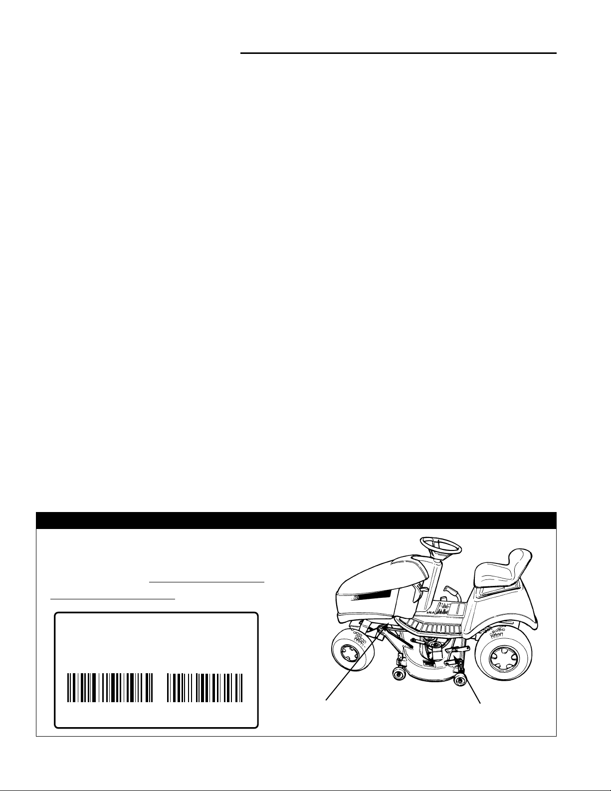
MODELS COVERED, IDENTIFICATION NUMBERS, AND
BASIC CONFIGURATIONS
Mower Deck
Identification Tag
Tractor
Identification Tag
TRACTOR & MOWER IDENTIFICATION TAG LOCATIONS
169XXXX
MFG
Simplicity Manufacturing, Inc.
Port Washington, WI 53074-0997 U.S.A.
SERIAL
XXXXX
When contacting your Authorized
Dealer for replacement parts, service,
or information YOU MUST HAVE
THESE NUMBERS.
This manual contains service information for the models
listed on the following page (and similar models produced after this manual’s printing). Consult the
Identification Tag located on the tractor frame for the
manufacturer’s identification number and serial number.
Always use the manufacturer’s identification number and
serial number when ordering parts or documentation.
Attachments are not covered in this manual. Refer to the
attachment operator’s manual or authorized dealer for
service information.
Transmissions are identified by identification number
tags located on the transmission casing.
At the time of this printing Regent / 500 / 2500 series
tractors have been built with four basic powertrain configurations. These four basic types are referred to throughout this manual and denoted by their transmission.
When a service procedure is specific to a certain model,
that model will be identified as one of the groups listed at
right.
MODEL IDENTIFICATION
Hydro-Gear 0500 and 0650 Models are similar utilizing
the same brake linkage . Their engines and transmissions are also similar. Their primary difference is the
linkage used to connect the transmission to the foot
pedal.
Tuff Torq K-56 Models are radically different from
Hydro-Gear Models. Tuff Torq models can be easily recognized by their Kohler engine.
Peerless Models are distinct in that they are gear drive
and require clutching.
Hydro-Gear 0500 Models
Engine: Briggs and Stratton 14HP Vanguard
Transmission: Hydrostatic, Hydro-Gear 318-0500, or
Hydro-Gear 322-0500
Deck: 38” Twin Blade
Hydro-Gear 0650 Models
Engine: Briggs and Stratton 16HP Vanguard
Transmission: Hydrostatic, Hydro-Gear 322-0650
Deck: 44” Triple Blade
Tuff Torq K-56 Models
Engine Kohler Command 14HP & 16HP
Transmission: Hydrostatic, Tuff Torq K56
Deck: 38” Twin Blade and 44” Triple Blade
Peerless Models, “Gear Drive”
Engine: 14HP Kohler Command,
16HP Kohler Command,
15.5 HP Briggs & Stratton Diamond I/C,
14HP Briggs & Stratton Diamond I/C
Transmission: Gear Drive, Peerless MST-205-515 or
MST-205-515A
Deck: 38” Twin Blade and 44” Triple Blade
SSAAMMPPLLEE
Page 5

1-3
1 General Information
Models Covered In This Manual
Mfg. No.
1692354 14HP Regent Hydro
1692588 514H, 14 HP Hydro
1692591 2514H, 14 HP Hydro
1692593 14HP Regent Gear
1692595 514G, 14 HP Gear
1692597 2514G, 14 HP Gear
1692599 14HP Regent Gear (Export)
1692601 14Hp Regent Hydro (Export)
1692760 16HP Regent Gear
1692762 16HP Regent Hydro
1692829 516G, 16 HP Gear
1692831 516H, 16 HP Hydro
1692835 2516H, 16 HP Hydro
1693100 2514G. 14HP Gear
1693102 2514H, 14HP Hydro
1693104 2516H, 16 HP Hydro
1693074 14HP Regent Gear
1693076 14HP Regent Gear (Export)
1693080 14HP Regent Hydro
1693082 14HP Regent Hydro (Export)
1693084 16HP Regent Gear
1693086 16HP Regent Gear (Export)
1693088 16HP Regent Hydro
1693090 16HP Regent Hydro(Export)
1693092 514G, 14 HP Gear
1693094 514H, 14HP Hydro
1693098 516H, 16HP Hydro
1693100 2514G, 14HP Gear
1693102 2514H, 14HP Hydro
1693104 2516H, 16HP Hydro
1693323 Regent, 14HP Gear
1693325 Regent, 14HP Hydro
1693327 Regent, 16HP Gear
1693329 Regent, 16HP Hydro
Tractors
Description
Description
Mower Decks
1692358 38” Mower Deck
1692589 38” Mower Deck
1692744 44” Mower Deck
1692851 44” Mower Deck
1693078 38” Mower Deck
Mfg. No.
1693331 Regent, 14HP Gear (Export)
1693333 Regent, 14HP Hydro (Export)
1693335 Regent, 16HP Gear (Export)
1693337 Regent, 16HP Hydro (Export)
1693339 514G, 14HP Gear
1693341 514H, 14HP Hydro
1693343 516H, 16HP Hydro
1693345 2514G, 14HP Gear
1693347 2514H, 14HP Hydro
1693349 2516H, 16HP Hydro
Sports Series Tractors
1692873 Packers Regent 14HP Hydro
1692957 Vikings Regent 14HP Hydro
1692959 Steelers Regent 14HP Hydro
1692961 Panthers Regent 14HP Hydro
1692963 Chiefs Regent 14HP Hydro
1692965 Colts Regent 14HP Hydro
1692967 Badgers Regent 14HP Hydro
1692969 Hawkeyes Regent 14HP Hydro
1692971 Wolverines Regent 14HP Hydro
1692973 Spartans Regent 14HP Hydro
1692975 Nittany Lions Regent 14HP Hydro
1693190 New England Patriots 14HP Regent
1693192 Packers Superbowl 14HP Regent
1693194 Dallas Cowboys 14HP Regent
1693196 New York Giants 14HP Regent
1693198 Tennessee Volunteers 14HP Regent
1693200 Indiana Hoosiers 14HP Regent
1693202 Ohio State Buckeyes 14HP Regent
1693212 Chicago Bears 14HP Regent
1693214 Detroit Lions 14HP Regent
1693216 Philadelphia Eagles 14HP Regent
Mfg. No.
Description
1693079 38” Mower Deck
1693169 44” Mower Deck (Export)
1693188 44” Mower Deck
1693189 44” Mower Deck
1693218 38” Mower Deck (Export)
Mfg. No.
Description
NOTE: This list is correct and complete at the time of
printing. Though your tractor may not appear on this list,
it may be covered in part or in full by this manual
Page 6

1 General Information
Introduction
1-4
INTRODUCTION
This manual is divided into sixteen major sections of service information.
1. General Information
Contains general information such as models and manufacturing numbers, general repair instructions for components, and important safety instructions for operating and
servicing the units.
2. Troubleshooting
Provides troubleshooting information pertaining to unit
operation.
3. Maintenance
Contains basic service information for normal maintenance and off-season storage.
4. Adjustments
Contains basic service information and procedures for
adjustments.
5. Belt Replacement
Contains procedures for removing and installing belts.
6. Common Service Procedures
Contains common service procedures.
7. Electrical System Service
Contains electrical system component location, component replacement, and troubleshooting procedures.
8. Steering Component Service
Contains steering system component service procedures.
9. Drive Controls Service
Contains drive system component service procedures.
10. Transmission Removal & Installation
Contains procedures for removing and installing whole
transmission assemblies.
11. Transmission Tear-Down
Contains procedures for disassembling and reassembling transmissions.
12. Hood Assembly Service
Contains procedures for removing, disassembling, and
reassembling the hood and headlight bezel.
13. Seat & Seat Deck Service
Contains procedures for seat and seat deck service.
14. PTO Clutch Service
Covers removal and installation of the PTO clutch.
15. Miscellaneous Component Service
Covers removal of the throttle control, gas tank, and
other components not grouped in other sections.
16. Mower Deck Service
Covers common mower deck service procedures.
MANUAL CONTENT
This manual is intended primarily for use by dealer service personnel as a technical reference manual or as a
complement to normal service training.
While the information in this manual has been developed
to permit mechanics and service technicians to perform
most service procedures quickly and effectively, it is
assumed that those using this manual will have some
outdoor power equipment service experience or other
basic power equipment service training with similar types
of products.
In addition, it is assumed that all those performing service on these units are familiar with the general principles of operation of these units, and understand all operating controls, safety instructions, and normal handling
precautions for servicing large tractors and mowers.
Engine information is available from the appropriate
engine manufacturer in a separate service manual.
General engine information and basic engine troubleshooting information is provided, but is intended for
general guidance only. The engine manufacturer’s manual should always be consulted first before making any
major adjustments, part changes, or other major repairs.
This manual includes all relevant service information for
model years 1995 through 1998, and whenever necessary, includes inset illustrations or other references to
help identify previous part designs and alternative service procedures.
The service techniques in this manual also assume that
the person providing service has access to a standard
assortment of mechanic’s hand tools, and approaches
most disassembly and repair procedures with availability
of these basic tools in mind. Whenever specialized or
custom tools are available to save time, reduce effort, or
improve overall service efficiency, the most effective safe
repair method available should be utilized.
Since part numbers are subject to change and may vary
by model year and manufacturing number, all parts in
this manual are referred to by general description.
Specific part number information may be found in the
respective Parts Manual for the unit being serviced.
Always use the manufacturing number that appears on
the Identification Tag of the unit you are servicing to
identify component part numbers.
Page 7

1-5
1 General Information
Safety Rules
Read these safety rules and follow them closely. Failure to obey these rules could result in loss of control of
tractor, severe personal injury or death to you, or bystanders, or damage to property or equipment. The
mowing deck is capable of amputating hands and feet and throwing objects. The triangle in text
signifies important cautions or warnings which must be followed.
GENERAL OPERATION
• Read, understand, and follow all instructions in the
manual and on the unit before starting.
• Only allow responsible adults, who are familiar with
the instructions, to operate the unit.
• Clear the area of objects such as rocks, toys, wire,
etc., which could be picked up and thrown by the
blade(s).
• Be sure the area is clear of other people before mowing. Stop unit if anyone enters the area.
• Never carry passengers.
• Do not mow in reverse unless absolutely necessary.
Always look down and behind before and while travelling in reverse.
• Be aware of the mower discharge direction and do
not point it at anyone. Do not operate the mower
without either the entire grass catcher or the deflector
in place.
• Slow down before turning.
• Never leave a running unit unattended. Always
disengage the PTO, set parking brake, stop engine,
and remove keys before dismounting.
• Turn off the PTO switch to disengage the blades
when not mowing.
• Stop engine before removing grass catcher or
unclogging chute.
• Mow only in daylight or good artificial light.
• Do not operate the unit while under the influence of
alcohol or drugs.
• Watch for traffic when operating near or crossing
roadways.
• Use extra care when loading or unloading the unit
into a trailer or truck.
SLOPE OPERATION
Slopes are a major factor related to loss-of-control and
tip-over accidents, which can result in severe injury or
death. All slopes require extra caution. If you cannot
back up the slope or if you feel uneasy on it, do not mow it.
Do
• Follow manufacturer’s recommendations of wheel
weights or counterweights to improve stability.
• Mow up and down slopes, not across.
• Remove obstacles such as rocks, tree limbs, etc.
• Watch for holes, ruts, or bumps. Uneven terrain could
overturn the unit. Tall grass can hide obstacles.
• Use slow speed. Choose a low gear so that you will
not have to stop or shift while on the slope.
• Use extra care with grass catchers or other attachments. These can change the stability of the unit.
• Keep all movement on the slopes slow and gradual.
Do not make sudden changes in speed or direction.
Do Not
•
Do not
start or stop on a slope. If tires lose traction,
disengage the blade(s) and proceed slowly straight
down the slope.
•
Do not
turn on slopes unless necessary, and then,
turn slowly and gradually downhill, if possible.
•
Do not
mow near drop-offs, ditches, or embankments. The mower could suddenly turn over if a
wheel is over the edge of a cliff or ditch, or if an edge
caves in.
•
Do not
mow on wet grass. Reduced traction could
cause sliding.
•
Do not
try to stabilize the unit by putting your foot on
the ground.
•
Do not
use grass catcher on steep slopes.
WARNING - SLOPE OPERATION
Never operate on slopes greater than 30 percent (16.7°)
which is a rise of three feet vertically in 10 feet horizontally. When operating on slopes that are greater than 15
percent (8.5°) but less than 30 percent use front counterweights and rear wheel weights (see your dealer). Select
slow ground speed before driving onto slope. In addition
to front and rear weights, use extra caution when operating on slopes with rear-mounted grass catcher. Mow UP
and DOWN the slope, never across the face, use caution
when changing directions and DO NOT START OR STOP
ON SLOPE.
Page 8

1 General Information
Safety Rules
1-6
CHILDREN
Tragic accidents can occur if the operator is not alert to
the presence of children. Children are often attracted to
the unit and the mowing activity. Never assume that children will remain where you last saw them.
• Keep children out of the mowing area and under the
watchful care of another responsible adult.
• Be alert and turn unit off if children enter the area.
• Before and when backing, look behind and down for
small children.
• Never carry children. They may fall off and be seriously injured or interfere with safe unit operation.
• Never allow children to operate the unit.
• Use extra care when approaching blind corners, shrubs,
trees, or other objects that may obscure vision.
TRANSPORTING AND STORAGE
• Always observe safe refueling and fuel handling practices when refueling the tractor after transportation,
service, or storage.
• Always follow the engine manual instructions for
storage preparations when preparing the tractor for
both short and long term periods.
• Always follow the engine manual instructions for
proper start-up procedures when returning the unit to
service.
• Never store the unit or fuel container inside where
there is an open flame or pilot light, such as in a
water heater, gas furnace, or stove. Allow unit to cool
before storing. (“Cool” is defined as being cool
enough that all components can be touched: less
than 150 degrees Fahrenheit.)
GENERAL SAFETY
All WARNING, CAUTION, and instructional messages
appearing in decals on the tractor and mower being serviced must be carefully read and obeyed. Severe personal injury can result when these instructions are not
followed. The information is for your safety, as well as
those who operate the equipment, and it is important!
If any of these decals are lost or damaged, replace them
at once. See your Parts Manual for replacement information.
These labels are easily applied and will act as a constant
visual reminder to you, the operator, and others who may
use the equipment, to follow the safety instructions necessary for safe, effective operation.
Page 9

1-7
1 General Information
Safety Rules
SERVICE AND MAINTENANCE
The service information provided in this manual is
intended to provide you with the knowledge required to
perform a wide range of service procedures on the listed
equipment.
While appropriate safety reminders and safety warnings
have been included here and elsewhere in this manual,
you must also observe all appropriate shop safety rules
whenever performing these procedures.
No single manual, including this one, can include every
possible warning or safety instruction necessary to guarantee complete safety. You must apply your common
sense and knowledge of shop and power equipment
safety whenever performing service, whenever working
around others who are operating, servicing, or handling
equipment, and whenever you are present in a work
environment where hand or power tools, shop equipment, or outdoor power equipment may be present.
This includes taking the necessary safety precautions to
help ensure a safe workplace, exercising reasonable
care to avoid unsafe acts, and being alert for potential
hazards as you move about the workplace or engage in
various service activities.
If you encounter a service situation involving the use of
an unfamiliar tool, procedure, or part, and rereading the
appropriate section of this manual does not provide the
information you want, contact your Simplicity dealer
before proceeding. Never attempt a repair that you’re
not sure about, since help is usually never more than
just a phone call away.
Practicing safe service procedures not only helps protect
you and those you work around, it also contributes to
providing safe, reliable equipment .
Personal Protective Equipment
• Wear protective safety glasses whenever using hand
or power tools, shop equipment, and whenever working under power equipment to protect your eyes from
falling debris and small parts.
• Wear safety goggles or full face protection when handling battery electrolyte fluid, or when performing
grinding or sharpening operations that produce
sparks or flying debris. Extensive grinding may
require the use of protective sleeves and an apron.
• Wear work gloves when handling sharp surfaces
such as mower blades, or when working around
sharp edges. Never wear gloves that are loose fitting
or that have tie straps, as these could cause your
hands to get caught by rotating parts, resulting in
serious injury. Chemical-resistant Rubber gloves are
recommended when handling or pouring battery electrolyte.
• Steel-toe safety shoes are highly recommended to
protect feet from falling tools, heavy parts, and other
shop equipment.
Fuel Handling Safety
• Always use extra care when handling gasoline gasoline is highly flammable, and gasoline vapors
are explosive as well as toxic if inhaled.
• Never store fuel indoors, or refuel a unit indoors.
Gasoline vapors can easily travel unseen to distant
sources of ignition such as pilot lights or open flames
on water heaters, furnaces, stoves, or other gas
operated appliances, sparks from electric motors or
other electrically-operated tools and equipment, welding equipment, grinders, or burning smoking materials. Contact with these or any other sources of ignition will cause an explosion and/or fire, serious personal injury, and damage to property and equipment.
• Never transfer gasoline from one container to another
unless the containers are connected by an approved
grounding strap. Hand or power operated transfer
pumps can generate a static charge of electricity,
causing dangerous sparking and ignition of fuel or
fuel vapors. Always follow the pump manufacturer’s
safety and operating instructions.
• Use only approved containers for fuel, and always
handle the container with extreme care to avoid
spillage or leaking of explosive vapors.
• Never smoke or allow others in the area to smoke
while refilling the fuel tank, or when handling gasoline cans. Make sure any smoking materials that had
been in use in the area are fully extinguished before
opening a fuel can or starting refueling .
Page 10

1 General Information
Safety Rules
1-8
Exhaust Gas Safety
• Internal combustion engines produce and exhaust
Carbon Monoxide (CO), an odorless, colorless, gas
that causes dizziness, nausea, flu-like symptoms,
unconsciousness, or even brain damage or death, if
breathed for prolonged periods.
• If exposed to Carbon Monoxide gas, get to a fresh air
source immediately and seek medical attention. CO
builds up in your blood, and can cause lingering
symptoms or permanent damage if left untreated.
• Operate the unit outdoors or in a well ventilated area,
or pipe exhaust gases out of the work area to an outside location where the exhaust can be dissipated
safely away from doors, windows, air conditioners, or
other potential sources of outside-air intake that could
permit reentry of hazardous fumes.
• Never enter an enclosed area where an engine has
been running and exhaust gases have been allowed
to collect. Open adjacent windows or doors first to
permit outside air to ventilate the area, and allow sufficient time for a complete air exchange to occur.
Battery/Electrolyte Safety
• Lead-Acid batteries use an electrolyte containing sulphuric acid, a highly corrosive liquid that can cause
severe chemical burns if allowed to come into contact
with skin, or blindness if allowed to contact your eyes.
Always wear approved eye goggles or a full face
shield and protective gloves when handling electrolyte or filling the battery.
• Lead-acid batteries also produce hydrogen, a colorless, highly explosive gas that can be easily ignited
by a single spark. Charging the battery incorrectly or
hooking up jumper cables improperly can cause
sparking, and must be avoided. Always follow recommended battery charging and jumper cable procedures.
• When removing or installing battery cables, disconnect the negative cable FIRST, and reconnect it
LAST. If not done in this order, the positive terminal
could be accidentally shorted to the frame by a tool,
creating a dangerous spark that can ignite nearby
fuel vapors or escaping hydrogen gas from the battery.
• Keep battery securely fastened in position with vent
tube directed down and out of battery compartment.
Replace battery if electrolyte leakage occurs. Make
sure the battery vent tube is properly installed, and is
not plugged with clippings or other debris. Replace
the vent tube if cracked, damaged, or missing from
unit.
• Old batteries should be disposed of by recycling.
Electrical System Safety
• Loose connectors, worn wires, damaged wire insulation, and loose termination hardware can cause
sparks, short-circuits, and erratic equipment operation. Always check wiring for damage, and make
appropriate repairs before placing unit back into operation.
• Use care when working around exposed terminals to
prevent short-circuiting the electrical system.
Sparking, electric shocks, and damage to the system
may result from accidental contact between terminals
and metal hand tools.
Safe Elevation Of Unit
• Always support unit on approved jack stands when
working on an elevated unit, and keep unit from
rolling by engaging parking brake and placing wheel
chocks behind wheels still on floor or work table.
• Secure unit to work-surface of scissor-lift worktables
or other powered lift tables in accordance with the
manufacturer’s instructions. Unsecured units may
roll unexpectedly while work is being done, causing
injuries.
• Never work under an elevated unit unless it is properly supported by jack stands, locked from rolling with
wheel chocks or equivalent, and you can quickly
escape from under the unit in an emergency using a
rolling device such as a mechanic’s creeper.
• Always protect your eyes from falling debris or small
parts by wearing approved safety glasses or goggles.
• Remove the ignition key and disconnect the spark
plug wires before working under a unit. Accidental or
inadvertent starting could result in serious injuries.
Proper Tool Use
• Use power and hand tools only for the use that they
were designed. Never alter or modify tools, or improvise using tools that are not suitable for the job at
hand.
• Keep all hand and power tools in good repair, and put
them away when done to avoid cluttering the work
area. Use extra care when using corded tools
around moving or rotating parts such as belts and
pulleys, since the cord could get caught and suddenly
pull the tool, or you, into the area of moving parts.
• Always check the unit to ensure that all hand and
power tools and tool attachments have been
removed from the unit after use. Small tools and tool
attachments left on the equipment can fall into the
cutting path when the unit is placed into service, and
become a hazard to bystanders if struck by mower
blades.
Page 11

1-9
1 General Information
Safety Rules
Work Area Safety
• Always keep the work area clear of clutter from discarded parts, and debris from parts boxes or packaging materials. Small parts, hardware items, and other
debris or refuse left lying around can become slip,
trip, and fall hazards if not removed and discarded of
properly.
• Always observe general shop safety rules for housekeeping, and tend to oil spills and other spilled fluids
promptly to prevent slip and fall injuries.
• Allow sufficient work area around the equipment you
are working on to permit comfortable working positions. Never put yourself in a position that would prevent you from escaping quickly in the event of emergencies such as sudden shifts in equipment position,
fire, or other situations requiring an immediate reaction on your part.
Compressed Air Safety
• Always use care when using compressed air to blow
dirt and debris off equipment - always direct the air
blast away from yourself and others in the area, and
protect your eyes with safety glasses to prevent injury
from particles that may blow back toward your face.
• Never use high pressure air directly against your skin
to clean dirt and debris - the air pressure could actually force foreign material or fluids into your skin,
causing serious injuries.
• Use care when filling tires - lawn and garden tractors
utilize low pressure tires, and over-pressurization is
hazardous to you and anyone who operates the
equipment with improper tire pressures. Always consult the air pressure recommendations for the unit
involved before adding additional air to the tires.
Grease & Lubricant Safety
• Normal service and maintenance involves the use of
oils and greases that could present a fire hazard if
not handled properly. Always dispose of oily rags
properly to prevent fires caused by spontaneous
combustion.
• Spilled lubricants pose dangerous slip hazards and
must be taken care of immediately. Wipe up spills
carefully, or use absorbent materials to soak up
spilled fluids. Always dispose of rags, paper towels,
and other saturated absorbents properly.
• Store oils and greases away from flame or other ignition sources. Petroleum-based fluids can be ignited
by smoking materials and sparks - always treat oils
and greases as potentially flammable materials.
Always cap oil and grease containers when done
using, and store or dispose of properly.
General Servicing Safety
• Always check safety devices and switches for proper
operation - never alter these devices or make temporary or makeshift repairs. Use only factory-authorized parts and procedures, and check newlyinstalled parts for proper operation.
• Make sure all hardware items are properly tightened,
especially blade attachment bolts. Replace any hardware that appears damaged.
• Check brake operation, and adjust or repair as
required. Always comply with factory specifications
on settings and adjustments.
• Check grass catcher components for wear, damage,
or deterioration, and replace with factory authorized
parts if necessary.
• Always make repairs using factory authorized
replacement parts only. Using parts that don’t meet
factory specifications can result in sudden or premature failures, poor or erratic equipment performance,
and potential safety hazards to operators and
bystanders.
• Always comply with factory specifications on settings
and adjustments when installing new parts, making
repairs, or performing routine service procedures.
• Always test repairs before releasing units to customers, paying special attention to any items that are
safety-related. Correct any problems noted, and recheck to ensure that the problems have been fully
remedied.
• Make sure all safety and operating instruction decals
are legible, properly located, and securely attached.
Replace any decals that can’t be read or are in danger of falling off.
• Always advise equipment owners of any potential
operating or safety problems that may be arising due
to anticipated wear, and request that the owner
address the problem before a hazard develops.
• Never allow a unit to be placed back into service if a
serious safety or operating problem is evident.
Advise the owner of the problem and the possible
hazards associated with the problem, and request
permission to correct the deficiencies.
• Use extreme care when working on older models that
do not have all of the latest safety devices and
switches. Disengage the PTO and transmission
before starting the unit, or commencing repairs.
• Always use care when removing or installing parts to
prevent damage from dropping or rough handling.
Support heavy parts properly to prevent damage or
personal injury to yourself and others.
Page 12

1 General Information
Repair Information
1-10
GENERAL REPAIR INFORMATION
In addition to providing specific repair procedures for the
equipment listed at the beginning of this section, this
manual provides the following additional general instructions for dealing with repairs to various types of components.
This information is designed to help you deal more effectively with these components by providing basic service
knowledge and other useful tips.
Bearings & Bushings
Roller bearings, ball bearings, and bushings are used to
provide support to rotating shafts and other parts such as
gears, pulleys, and sprockets that are used to transmit
rotary motion. Over time, bearings and bushings may
require additional lubrication to transmit this rotary
motion with minimal friction, or may need replacement
due to normal operation and wear. Normal service for
bearings and bushings includes removal, cleaning,
inspection, lubrication, and replacement.
REMOVAL
Most bearings and bushings used on the listed equipment can be easily removed by following the appropriate
detailed procedures found throughout this manual. Care
should always be exercised to avoid scratching or damaging the bearing or bushing, the mounting shaft, and
surrounding components. Bearing or bushing removal is
usually necessary when excessive play or wobble is
noticed on the part it supports, when unusual noise or
vibration is apparent, or when a burning smell is present
at the bearing location.
CLEANING
Sealed bearings and bushings can be cleaned by careful
wiping with a cloth. Bearings with one-sided or removable shields and plain bushings can be cleaned by
immersion in safety solvent, and brushing with a part
cleaning brush. Oil-impregnated bushings, and bushings
made of nylon or other synthetic materials, can be
cleaned with safety solvents, or wiped clean, but should
not be immersed in solvent for periods longer than that
necessary to remove heavy or caked-on build-ups of
grease. All petroleum-based solvents are flammable, so
appropriate precautions regarding flames, sparks, and
other ignition sources should always be observed.
Gasoline should never be used because of its volatility
and its highly toxic nature.
INSPECTION
Once cleaned, bearings can be properly inspected for
wear, scratches, visible damage such as corrosion,
cracked seals or scorching, and rough, or noisy, operation. Bushings can be visually checked for scratches,
uneven wear, or other visual damage.
LUBRICATION
After passing inspection, bearings and bushings should
be lubricated in accordance with factory specifications,
and reinstalled according to the appropriate installation
instructions. New bearings and bushings must also be
properly lubricated before use. For optimal performance,
and as a practical preventive maintenance measure,
bearings and bushings used in pairs or multiple sets
should all be replaced at the same time.
Belts & Pulleys
Belts and pulleys transmit rotary motion from power
sources to work components, providing the force needed
to drive transmissions, operate mower decks, and power
various attachments. This continual use eventually
causes belts to wear out, and over time may also require
the replacement of pulleys and pulley bearings.
Belt wear and various types of damage are easily
checked by visual examination, which is covered in
greater detail elsewhere in this manual. Pulleys may
also be checked visually for wear or apparent damage,
but pulley bearings usually require removal, cleaning,
and inspection to determine if replacement is required.
Belt and pulley life can be optimized by making sure that
proper belt tension and alignment are observed when
belts are installed. Proper belt tension and alignment
should also be maintained by performing periodic checks
and adjustments. In addition, only factory authorized
replacement belts will minimize problems caused by
size, thermal instability, and variations in quality.
Electrical Parts
The electrical parts used on these units have been
specifically engineered for outdoor power equipment,
and are designed to provide years of reliable operation.
As with all electrical components and systems, electrical
contacts must be kept clean and dry, and all terminations
must be securely fastened or connected. Also, all electrical components, wiring, and connectors should be periodically inspected for corrosion, signs of excessive heat
build-up, or other damage that signals that it is time to
repair or replace the item.
Specific procedures for electrical troubleshooting and
most common repairs is covered in separate sections of
this manual.
Page 13

1-11
1 General Information
Repair Information
Fasteners & Hardware
All hardware and fasteners used in this equipment must
meet factory specifications for SAE grade, size, and
torque, and must be kept securely tightened. Locking
hardware that degrades with use should be replaced
when service is performed in affected areas. Always
observe factory specifications for torque, or consult the
torque chart for torque information.
Genuine Replacement Parts
Only factory authorized replacement parts should be
used when making repairs or performing routine maintenance. The use of parts that do not meet stringent factory specifications can cause poor performance, premature
failures, and lead to potential safety hazards. In addition,
the use of non-factory authorized replacement parts will
void your warranty.
Paint
The paint on outdoor power equipment provides for an
attractive appearance, as well as a barrier to corrosion
caused by exposure to moisture in the environment.
Scratches, abrasions, and other damage to painted surfaces should be repaired promptly to prevent the formation of rust and premature part failure. Factory supplied
paints are available that provide both an accurate color
match and superior corrosion resistance.
Required Tools & Equipment
All repairs in this manual can be accomplished with standard mechanic’s hand tools. The use of appropriate
power tools such as impact wrenches and power drivers
may aid in part removal and replacement, but care must
be exercised to avoid causing damage to components
from excessive tightening. Transmission service, steering service, tire and wheel service, and service to components located under the frame also requires the use of
a jack with suitable capacity, and jack stands to support
the unit being worked on.
Systems Checks
In addition to performing individual component service,
components affected by related parts changes should
also receive attention at the time service is performed.
Examples of this include part replacements that are part
of a safety device, electrical components, transmission
components, and pulleys that are part of the same power
delivery system. Giving attention to related parts will
help ensure that the parts most likely to be affected by
the wear of similar or nearby parts, or parts subjected to
the same amount of stress or wear, are given appropriate attention before a failure can occur.
Page 14

1 General Information
Specifications
1-12
14 HP Briggs & Stratton
Make: Briggs & Stratton - 4 cycle air cooled
Model & Type: See engine l.D. plate
Horsepower: 14 HP @ 3600 rpm (Eng. Mfg’s. Rating)
Cylinder: 1 horizontal
Bore & Stroke: 3.44 x 3.06 inches (87.3 x 77.7 mm)
Displacement: 28.4 cu. in. (465 cc)
Construction: Overhead valve, cast iron sleeves, aluminum
crankcase
Electrical: Vanguard - 12 volt 9 amp. alternator regulated
battery, 12 volt, 340 cranking amps, 41 minute
reserve capacity.
Diamond - unregulated 3 amp. DC charging
circuit.
Governor: Mechanical
Oil Capacity: 4.0 pints w/filter (1.9 L)
Ignition: Magnetron electronic
Charging: Diamond: Unregulated 3-amp DC,
Vanguard: Unregulated 9-amp DC
Air Cleaner: Ducted paper cartridge and foam pre-cleaner
Fuel Tank: High density polyurethane construction; 2 gal-
lons (7.57 liters) of “regular” grade leaded or
non-leaded gasoline.
Muffler Large, low back pressure, remote canister type
Starter: 12 volt electric gear drive
15.5 HP Briggs & Stratton
Make: Briggs & Stratton - 4 cycle air-cooled
Model & Type: Diamond I/C
Horsepower: 15.5 HP
Cylinder: 1 horizontal
Bore & Stroke: 3.44in.(87.3)mm
Displacement: 28.4cu.in.(465cc)
Construction: Overhead valve, Dura Bore Sleeves,
Aluminum Crankcase.
Electrical: 12 volt 9 amp, alternator
regulated battery, 12 volt, 340 cranking
amps, 41 minute reserve capacity.
Governor: Mechanical
Oil Capacity: 3 Pints w/Filter (1.4 L)
Ignition: Magnetron Electronic
Charging: Regulated 9 amp DC charging circuit
Air Cleaner: Tri-Clean
Fuel Tank: High Density polyurethane construction;
2 gallons (7.57 liters) of “regular” grade
leaded or non-leaded gasoline.
Muffler: Simplicity Custom Muffler
Starter: Electric
Specifications
ENGINE
16 HP Kohler Command
Make Kohler
Model Command CV16S
Horsepower 16 @ 3600 rpm
Cylinder 1 horizontal
Bore 3.55 in (90 mm)
Stroke 2.64 in (67 mm)
Displacement 26.0 Cu. in (426 cc)
Construction Overhead Valve, Cast-Iron Sleeve,
Aluminum Crankcase
Electrical System 12 Volt, 15 amp. Alternator Regulated
Battery: 12 Volt, 340 Cold Cranking amps,
23 Min. Reserve Capacity
Ignition High Energy Electronic Ignition
Air Cleaner Ducted Paper Cartridge and Foam Pre-cleaner
Lubrication Full Pressure Lube w/Oil Filter
Oil Capacity 4.0 Pints w/Filter (1.9 L)
Fuel Tank Material: High-Density Polyethylene,
Transparent
Capacity: 2.0 Gallons (7.5 L)
Muffler Quiet Compact, Low Back Pressure
14 HP Kohler Command
Make Kohler
Model Command CV14S
Horsepower 14 @ 3600 rpm
Cylinder 1 horizontal
Bore 3.43 in (87 mm)
Stroke 2.64 in (67 mm)
Displacement 24.3 Cu. in (398 cc)
Construction Overhead Valve, Cast-Iron Sleeve,
Aluminum Crankcase
Electrical System 12 Volt, 15 amp. Alternator Regulated
Battery: 12 Volt, 340 Cold Cranking amps
23 Min. Reserve Capacity
Ignition High Energy Electronic Ignition
Air Cleaner Ducted Paper Cartridge and Foam Pre-cleaner
Lubrication Full Pressure Lube w/Oil Filter
Oil Capacity 4 Pints w/Filter (1.9 L)
Fuel Tank Material: High Density Polyethylene,
Transparent
Capacity: 2.0 Gallons (7.5 L)
Muffler Quiet Compact, Low Back Pressure
Page 15

1-13
1 General Information
Specifications
16 HP Briggs & Stratton
Make: Briggs & Stratton - 4 cycle air cooled
Model & Type: Vanguard
Horsepower: 16 HP
Cylinder: 1 horizontal
Bore & Stroke: 3.44 in./87.3 MM (3.06 in./77.7 MM)
Displacement: 28.4 cu.in.(465cc)
Construction: Overhead valve, Cast Iron Sleeves,
Aluminum Crankcase.
Electrical: 12 volt 9 amp, alternator regulated battery,
12 volt, 340 cranking amps, 41 minute
reserve capacity.
Governor: Mechanical
Oil Capacity: 3.5 Pints w/Filter (1.7 L)
Ignition: Magnetron Electronic
Charging: Regulated 9 amp DC charging circuit
Air Cleaner: Dual Element
Fuel Tank: High Density polyurethane construction;
2 gallons (7.57 liters) of “regular” grade
leaded or non-leaded gasoline.
Muffler: Simplicity Custom Muffler
Starter: 12 volt electric gear drive
TRANSMISSION
Peerless (Gear Drive) Models
Type Peerless MST 205,
Spur Gear
Material Shaft: Hardened
Bearings: Needle Roller & Bushings
Lubrication EP 90 Oil
Speeds Five Forward, One Reverse
Speeds 1st: 1.0 MPH (1.6 km/h)
@ 3400 rpm 2nd: 2.0 MPH (3.2 km/h)
3rd: 3.0 MPH (4.8 km/h)
4th: 4.2 MPH (6.7 km/h)
5th: 4.7 MPH (7.5 km/h)
Rev: 1.4 MPH (2.2 km/h)
Differential Bevel Gear Type
Axle Shaft .75 in
Continuous Torque 225 ft. lbs.
Output
Drawbar Rating 16 HP: 300 lbs., 14 HP: 321 lbs.
Maximum Weight 525 lbs.
on Axle
Tuff Torq K-56 Hydro Models
Type Hydrostatic, Tuff Torq K56
Pump Variable Displacement Axial Piston
Motor Fixed Displacement Axial Piston
Control Single Pedal Foot Control
with Release Valve for Manually Pushing.
Hydraulic Fluid 10w 30 Premium Engine Oil
Speeds Forward: 0-5.6 MPH (9.0 km/h)
@ 3400 rpm Reverse: 0-3.0 MPH (4.6 km/h)
Differential Bevel Gear Type
Axle Shaft .75 in
Continuous Torque 170 ft. lbs.
Output
Drawbar Rating 227 lbs.
Maximum Weight 673 lbs.
on Axle
Hydro-Gear 0500 / 0650 Models
Type Hydrostatic, Hydro-Gear 318-0500, 322-0500,
or 322-0650
Pump Variable displacement axial piston
Motor Fixed displacement axial piston
Control Single Pedal Foot Control
with Release Valve for Manually Pushing.
Hydraulic Fluid 20W-50 Premium Engine Oil
Ground speeds Forward: 0-4.7 mph (7.5 km/h)
@ 3400 rpm: Reverse: 0-2.6 mph (4.1 km/h)
Differential: Bevel Gear Type
Axle Shaft: .75 in.
Continuous Torque 0500 Models: 135 ft. lbs.,
Output 0650 Models: 160 ft. lbs.
Drawbar Rating 0500 Models: 193 lbs., 0650 Modes: 213 lbs.
Maximum Weight 0500 Models: 500 lbs., 0650 Models: 540 lbs.
on Axle
Page 16

1 General Information
Specifications
1-14
CONTROLS
Steering Full Circle Steering Wheel System, Gear and
Sector, 1.5 turns Lock to Lock.
Clutch/Brake Location Right Front
Pedal Combination Clutch/Brake Pedal
Parking Brake Foot / Hand Lock
Ground Speed Right side of seat deck
Shift Lever (Gear)
Ground Speed Right side foot rest
Foot Pedal (Hydro)
Throttle Control Combination Speed & Choke Control on left
side of dash board.
Key Switch Starter and Magneto ON/OFF Switch located
on Right side of seat deck
Mower Drive Electric Clutch PTO Switch located on right side
of seat deck
CHASSIS
Frame Heavy Gauge Steel Channel - 12/14 Gauge
Engine Mounting: Above Front Axle
Pivot Point Location: Rear Carrier
Rear Wheels Tire Size: 20 x 8-8 Turf Type or 18 x 8.50 -8
Inflation Pressure: 12-15 psi (82-103 kPa)
Front Wheels Tire Size: 15 x 6.00-6
Inflation Press.: 12-15 psi (82-103 kPa)
Bearings: Sintered Iron with Grease Fittings
Accessibility Hood Tips Forward for Engine,
Seat Tips Forward for Battery.
Seat High-Back, Quick Adjust, Spring Suspension
Turning Radius Inside Rear Tire: 14 in (36 cm)
Fuel Tank Material: Non-Corrosive Polyethylene
Capacity: 2 Gallons (7.5 L)
DIMENSIONS
Tractor
Overall Length 68 in (172 cm)
Overall Width 36 in (92 cm)
Height At Steering Wheel: 41 in (104 cm)
To Top of Engine Cover: 34 in (86 cm)
Wheel Base 50 in (127 cm)
Weight (Apx. Net) 371 lbs. (168 kg)
w/44 in mower 463 lbs. (210 kg)
Tractor Height
w/Snowcab est. 70 in (177 cm)
Tractor Length
w/Snowthrower est. 90 in (228 cm)
Tractor Length
w/Dozer Blade est. 86 in (218 cm)
44” Mower
Thickness 12 Ga.
Effective Cutting
Width 44 in Mower - 44 in (111.8 cm)
Overall Width
with Deflector 56 in (142.2 cm)
with Turbo 44 in Mower - 58in (147 cm)
Weight 107 lbs. (49 kg)
Cutting Height Variable: 1.5 to 3.9 in (3.8 to 10 cm)
Blade Arrangement Three Staggered Blades
Mower Drive V-Belt from Tractor PTO Electric Clutch
Spindle Bearings Sealed Ball Bearings - Lube Fitting Provided
38” Mower
Thickness Early Models: 14 Ga., Later Models: 12-Ga.
Effective Cutting
Width 38 in Mower - 38 in (97 cm)
Overall Width
with Deflector 49.5 in (126 cm)
with Turbo 38 in Mower - 51.5 in (131 cm)
Weight 81 lbs. (36.7 kg)
Cutting Height Variable Between 1.5 and 3.9 in (3.8 and 10 cm)
Blade Arrangement Two Staggered Blades
Mower Drive V-Belt from Tractor Engine PTO Electric Clutch
Spindle Bearings Sealed Ball Bearings - Lube Fitting Provided
Page 17
1-15
1 General Information
Hardware Identification & Torque Specifications
Torque Specification Chart
FOR STANDARD MACHINE HARDWARE (Tolerance ±20%)
Hardware
Grade
SAE Grade 2 SAE Grade 5 SAE Grade 8
Size Of
in/lbs in/lbs
in/lbs
Hardware ft/lbs Nm. ft/lbs Nm. ft/lbs Nm.
8-32
19
2.1
30
3.4
41
4.6
8-36
20
2.3
31
3.5
43
4.9
10-24
27
3.1
43
4.9
60
6.8
10-32
31
3.5
49
5.5
68
7.7
1/4-20
66
7.6 8 10.9 12 16.3
1/4-28
76
8.6 10 13.6 14 19.0
5/16-18 11 15.0 17 23.1 25 34.0
5/16-24 12 16.3 19 25.8 27 34.0
3/8-16 20 27.2 30 40.8 45 61.2
3/8-24 23 31.3 35 47.6 50 68.0
7/16-14 30 40.8 50 68.0 70 95.2
7/16-20 35 47.6 55 74.8 80 108.8
1/2-13 50 68.0 75 102.0 110 149.6
1/2-20 55 74.8 90 122.4 120 163.2
9/16-12 65 88.4 110 149.6 150 204.0
9/16-18 75 102.0 120 163.2 170 231.2
5/8-11 90 122.4 150 204.0 220 299.2
5/8-18 100 136 180 244.8 240 326.4
3/4-10 160 217.6 260 353.6 386 525.0
3/4-16 180 244.8 300 408.0 420 571.2
7/8-9 140 190.4 400 544.0 600 816.0
7/8-14 155 210.8 440 598.4 660 897.6
1-8 220 299.2 580 788.8 900 1,244.0
1-12 240 326.4 640 870.4 1,000 1,360.0
NOTES
1. These torque values are to be used for all hardware
excluding: locknuts, self-tapping screws, thread forming
screws, sheet metal screws and socket head setscrews.
2. Recommended seating torque values for locknuts:
a. for prevailing torque locknuts - use 65% of grade 5
torques.
b. for flange whizlock nuts and screws - use 135% of
grade 5 torques.
3. Unless otherwise noted on assembly drawings, all torque
values must meet this specification.
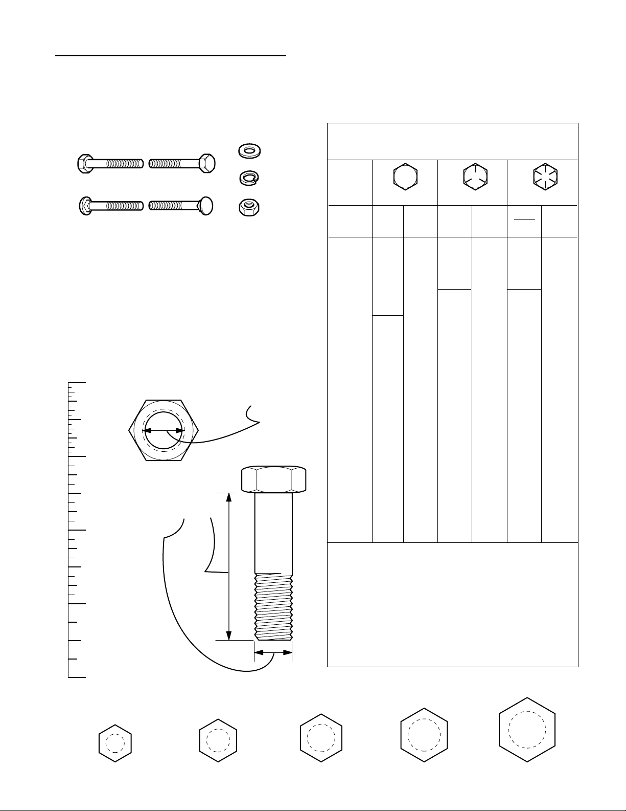
Hardware Identification & Torque Specifications
Common Hardware Types
3/8
5/16
1/4
1/2
DIA.
7/16
DIA.
Wrench & Fastener Size Guide
Standard Hardware Sizing
When a washer or nut is identified as 1/2”, this is the
Nominal size
, meaning the
inside diameter
is 1/2 inch; if a
second number is present it represent the
threads per inch
When bolt or capscrew is identified as 1/2 - 13 x 2”, this
means the
Nominal size
, or
body diameter
is 1/2 inch; the
second number represents the
threads per inch
(13 in this
example, and the final number is the
body length
of the
bolt or screw (in this example 2 inches long).
The guides and ruler furnished below are designed to
help you select the appropriate hardware and tools.
Hex Head Capscrew
Washer
Carriage Bolt
0
1/4 3/4
1/2
1
1/4 3/4
1/2
Nut, 1/2”
Screw, 1/2 x 2
2
1/4 3/4
1/2
3
1/4 3/4
1/2
4
Body
Diameter
Body
Length
Lockwasher
Hex Nut
Inside
Diameter
No
Marks
Page 18

1-16
1 General Information
Notes
Page 19

2 - 1
2 Troubleshooting
Table of Contents
SECTION CONTENTS
Troubleshooting
Troubleshooting Chart.................................................................. 2-2
Troubleshooting Common Mowing Problems .............................. 2-4
SECTION 2. TROUBLESHOOTING
Page 20

2 - 2
2 Troubleshooting
Troubleshooting Chart
WARNING
Before beginning any service work, turn the PTO
off,set the parking brake, turn the ignition switch
off, remove the key, disconnect the spark plug
wire, and disconnect the negative battery cable.
Never attempt to perform repairs while the engine
is running.
FAILURE TO COMPLY WITH THIS, AND OTHER,
SAFETY REQUIREMENTS CAN RESULT IN
SERIOUS PERSONAL INJURY.
TROUBLESHOOTING
The troubleshooting guide below lists some common
problems, their causes, and remedies.
See the repair information in the following sections for
instructions on how to perform most of these minor
repairs yourself. If you prefer, all of these procedures
can be performed for you by your local authorized dealer.
TROUBLESHOOTING THE TRACTOR
PROBLEM CAUSES REMEDIES SEE SECTION
Engine will not 1. Ground speed control lever Shift into neutral. N/A
turnover or start. not in neutral-start position.
2. PTO (electric clutch) switch Place in OFF position. N/A
in ON position.
3. Out of fuel. If engine is hot, allow it to cool, then refill 3
the fuel tank.
4. Engine flooded. Move throttle control out of CHOKE position N/A
5. Circuit breaker tripped. Wait one minute for automatic reset. 7
Replace if defective.
6. Battery terminals require Clean Battery. 3
cleaning.
7. Battery discharged or dead. Recharge or replace. 6
8. Wiring loose or broken. Visually check wiring & replace broken or 7
frayed wires. Tighten loose connections.
9. Solenoid or starter motor faulty. Repair or replace. 7
10.Safety interlock switch. Replace as needed. 7
11.Spark plug(s) faulty, fouled Clean and gap or replace. See Engine Manual
or incorrectly gapped.
12.Water in fuel. Drain fuel & refill with fresh fuel. N/A
13.Gas is old or stale. Drain fuel & replace with fresh fuel. N/A
14.Foot pedal not fully depressed. Depress pedal. N/A
Engine starts hard 1. Fuel mixture too rich. Clean air filter. See Engine Manual
or runs poorly. 2. Carburetor adjusted incorrectly. Adjust Carburetor. See Engine Manual
3. Spark plug(s) faulty, fouled, or Clean and gap or replace. See Engine Manual
incorrectly gapped.
Engine knocks. 1. Low oil level. Check/add oil as required. 3
2. Using wrong grade oil. See engine manual.
Excessive oil 1. Engine running too hot. Clean engine fins, blower screen and See Engine Manual
consumption. air cleaner.
2. Using wrong weight oil. See engine manual.
3. Too much oil in crankcase. Drain excessive oil. 3
Engine exhaust 1. Dirty air filter. Replace air filter. See Engine Manual
is black. 2. Throttle is in choke position. Move throttle out of CHOKE position. N/A
Engine runs, but 1. Ground speed control lever Shift in forward or reverse. N/A
tractor will not drive. in neutral.
2. Transmission release lever Move into “drive” position. N/A
in “push” position.
(Hydro models only)
3. Drive belt is broken. Replace Belt 5
4. Drive belt slips. Adjust clutch/brake, replace belt. 4, 5
5. Brake is not fully released. Adjust Brake. 4
Page 21

2 - 3
2 Troubleshooting
Troubleshooting Chart
Tractor Troubleshooting Cont.
PROBLEM CAUSES REMEDIES SEE SECTION
Tractor drive 1. Pulleys or belt greasy or oily. Clean as required. N/A
belt slips. 2. Belt stretched or worn. Replace with correct belt. 5
3. Idler pulley pivot bracket Remove idler pulley, clean and lubricate. 3
“frozen” in declutched position.
Brake will 1. Brake is incorrectly adjusted. Adjust brake. 4
not hold. 2. Internal brake disc on Service as required. 4, 9
transaxle worn.
Tractor steers hard 1. Steering linkage is loose. Check and tighten any loose connections. 4, 8
or handles poorly. 2. Improper tire inflation. Check and correct. 3
3. Wheel bearings dry. Grease wheels and lubricate steering linkage 3
or steering linkage dry.
Drive belt does 1. Belt stops or belt tension Repair or adjust as needed. 4
not stop when clutch out of adjustment.
/brake is depressed.
TROUBLESHOOTING THE MOWER
PROBLEM CAUSES REMEDIES SEE SECTION
Mower will not raise. 1. Lift linkage sticking. Lubricate mower deck. 3
Mower cut is 1. Mower not leveled properly. Level mower deck. 3
uneven. 2. Tractor tires not inflated Check and inflate tires. 3
equally or properly.
Mower cut is rough 1. Engine speed too slow. Always mow at full throttle. N/A
looking. 2. Ground speed too fast. Slow down. N/A
3. Blades are dull. Sharpen or replace blades. 3, 6
4. Mower drive belt slipping Clean or replace belt as necessary. 5
because it is oily or worn.
5. Blades not properly fastened Tighten to 50-70 ft.lbs. (74 N.m.). 6
to arbors.
Engine stalls easily 1. Engine speed too slow. Always mow at full throttle. N/A
with mower 2. Ground speed too fast. Slow down. N/A
engaged. 3. Carburetor improperly adjusted. Adjust carburetor. See Engine Manual
4. Cutting height set too low. Cut tall grass at maximum cutting N/A
height during first pass.
5. Discharge chute jamming Cut grass with discharge pointing toward N/A
with cut grass. previously cut area.
Excessive mower 1. Blade mounting screws Tighten to 50-70 ft.lbs. (74 N.m.). 6
vibration. are loose.
2. Mower blades, arbors, Check and replace as necessary. 16
or pulleys are bent.
3. Mower blades are out Remove, sharpen, and balance blades. 3
of balance.
4. Belt installed incorrectly. Reinstall Correctly. 5
Excessive belt wear 1. Using incorrect belt. Replace with correct belt. 5
or breakage. 2. Bent or rough pulleys. Repair or replace. 16
Mower drive belt 1. Idler pulley spring broken or not Repair or replace as needed. 16
slips or fails properly attached.
to drive. 2. Belt stops out of adjustment. Check belt stops. 4, 16
3. Mower drive belt broken. Replace drive belt. 5
Page 22
2 Troubleshooting
Mowing Troubleshooting Chart
2 - 4
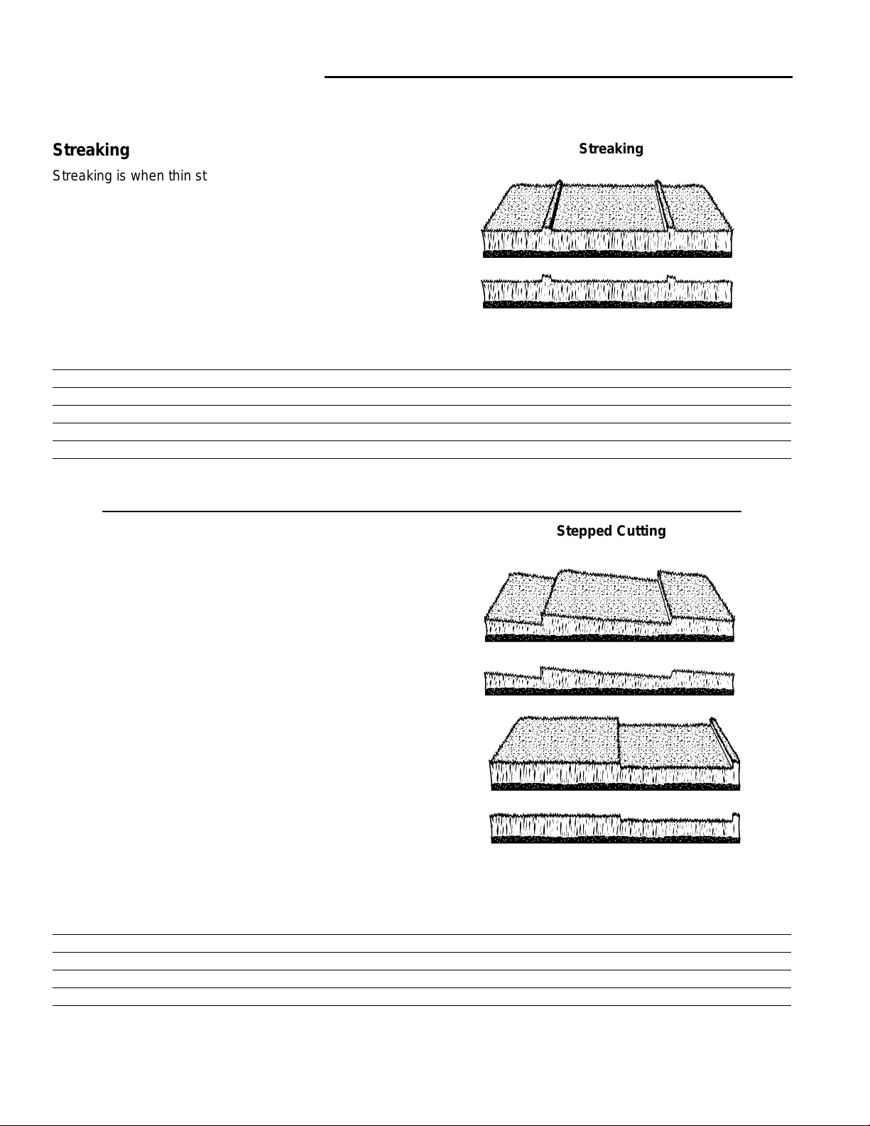
Stepped Cutting
Stepped cutting is sharp ridges or uneven levels left in
the lawn surface. Stepped cutting is usually caused by
mower deck damage or mis-adjustment, or damage to
mower blades.
CAUSE SOLUTION SEE SECTION
Deck is not leveled correctly Level the deck correctly 4
Tires are not properly inflated Check and inflate the tires 3
Blades are damaged Replace the blades 6
Deck shell is damaged Repair or replace the deck 16
Mower spindle is bent or loose Repair or replace the spindle 16
Blades are installed incorrectly Reinstall the blades correctly 6
Stepped Cutting
Streaking
Streaking
Streaking is when thin strips of uncut grass are left
behind the mower. Streaking is usually caused by
operator error or poor blade maintenance.
CAUSE SOLUTION SEE SECTION
Blades are not sharp Sharpen your blades 3
Blades are worn down too far Replace your blades 6
Engine speed is too slow Always mow at full throttle N/A
Ground speed is too fast Slow down N/A
Deck is plugged with grass Clean out the mower N/A
Not overlapping cutting rows enough Overlap your cutting rows N/A
Not overlapping enough when turning When turning your effective cutting width N/A
decreases–overlap more when turning
TROUBLESHOOTING COMMON MOWING PROBLEMS
Page 23
2 - 5
2 Troubleshooting
Mowing Troubleshooting Chart
Stingers
Stingers are sparse patches of uncut grass left behind
the mower. Stingers are usually caused by operator
error or poor blade maintenance.
CAUSE SOLUTION SEE SECTION
Blades are not sharp or are nicked Sharpen your blades 3
Blades are worn down too far Replace your blades 6
Engine speed is too slow Always mow at full throttle N/A
Ground speed is too fast Slow down N/A
Deck is plugged with grass Clean out the mower N/A
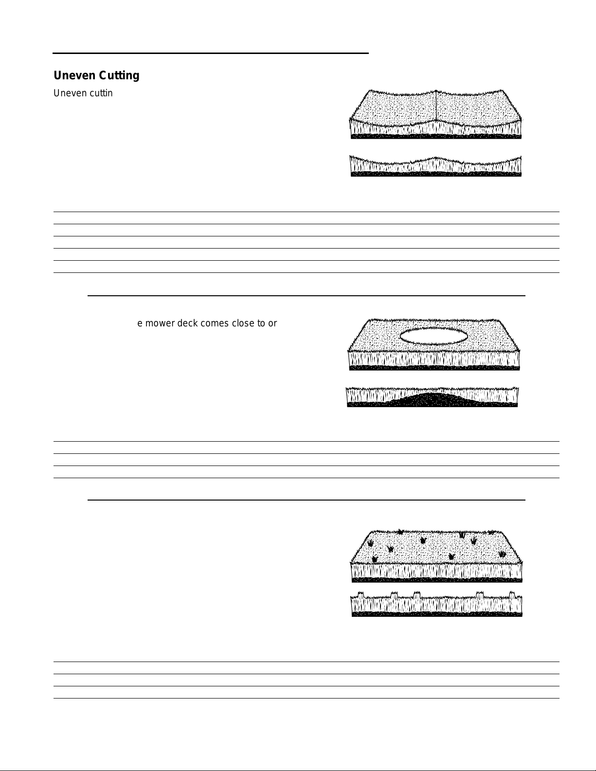
Uneven Cutting
Uneven cutting is waviness or smooth troughs in the
lawn surface. Uneven cutting is usually caused by
mower deck damage or mis-adjustment.
CAUSE SOLUTION SEE SECTION
Deck is not leveled correctly Level the deck correctly 4
Blades are dull or worn Sharpen or replace the blades 3, 6
Blades are damaged Replace the blades 6
Deck is clogged with grass clippings Clean out the deck N/A
Deck shell is damaged Repair or replace the deck 16
Mower spindle is bent or loose Repair or replace the spindle 16
Blades are installed incorrectly Reinstall the blades correctly 6
Scalping
Scalping is when the mower deck comes close to or hits
the ground. Scalping can be caused by the mower deck
mis-adjustment, unevenness in the lawn, or by mower
deck bouncing because the ground speed is too fast.
CAUSE SOLUTION SEE SECTION
Lawn is uneven or bumpy Roll or level the lawn N/A
Mower deck cutting height is set too low Raise the cutting height N/A
Ground speed is too fast Slow down N/A
Deck is not leveled correctly Correctly level the deck N/A
Tire pressure is low or uneven Check and inflate the tires 3
Uneven Cutting
Scalping
Stingers
Page 24

2 Troubleshooting
Notes
2 - 6
Page 25

3 - 1
3 Maintenance
Table of Contents
SECTION CONTENTS
Storage
Temporary Storage ...................................................................... 3-2
Long Term Storage ...................................................................... 3-2
Starting After Long Term Storage ................................................ 3-2
Maintenance Schedule
Maintenance Schedule................................................................. 3-3
Maintenance Procedures
Tire Pressure................................................................................ 3-3
Checking & Adding Gasoline ....................................................... 3-4
Engine Oil & Filter ........................................................................ 3-4
Check / Change Air Filter............................................................. 3-4
Replace Spark Plug ..................................................................... 3-4
Lubricate Rear Axles.................................................................... 3-5
Sharpen & Balance Mower Blades .............................................. 3-6
Tuff Torq K-56 Transmission Service........................................... 3-7
Hydro-Gear 0500 / 0650 Transmission Service........................... 3-7
Peerless Transmission Service.................................................... 3-7
Battery Maintenance
Check the Battery Fluid................................................................ 3-8
Cleaning the Battery and Cables ................................................. 3-8
Lubrication
Lubrication.................................................................................... 3-9
Safety Checks
Blade Brake Check .................................................................... 3-11
Safety Interlock System Checks ................................................ 3-11
SECTION 3. MAINTENANCE
Page 26

3 Maintenance
Storage
3 - 2
WARNING
Never store the unit, with gasoline in engine or
fuel tank, in a heated shelter or in enclosed,
poorly ventilated enclosures. Gasoline fumes may
reach an open flame, spark or pilot light (such as
a furnace, water heater, clothes dryer, etc.) and
cause an explosion.
Handle gasoline carefully. It is highly flammable
and careless use could result in serious fire
damage to your person or property.
Drain fuel into an approved container outdoors
away from open flame or sparks.
STORAGE
Temporary Storage (30 Days Or Less)
Remember, the fuel tank will still contain some gasoline, so
never store the unit indoors or in any other area where fuel
vapor could travel to any ignition source. Fuel vapor is also
toxic if inhaled, so never store the unit in any structure used
for human or animal habitation.
Here is a checklist of things to do when storing your unit
temporarily or in between uses:
• Keep the unit in an area away from where children may
come into contact with it. If there’s any chance of unauthorized use, disconnect the spark plug wires.
• If the unit can’t be stored on a reasonably level surface,
chock the wheels.
• Clean all grass and dirt from the mower.
NOTE: If storing your tractor between winter snow removal
jobs in a cold area, we suggest that you fill the fuel tank at
the completion of each job to prevent water condensation in
the fuel tank. Wait for engine to cool before filling tank.
Long Term Storage (Longer Than 30 Days)
Before you store your unit for the off-season, read the
Maintenance and Storage instructions in the Safety Rules
section, then perform the following steps:
1. Drain crankcase oil and refill with a grade of oil that will
be required when unit is used again.
2. Prepare the mower deck for storage as follows:
a. Remove mower deck from the unit.
b. Clean underside of mower deck.
c. Coat all bare metal surfaces with paint or light coat of
oil to prevent rusting.
3. Clean external surfaces and engine.
4. Prepare engine for storage. See engine owner’s
manual.
5. Clean any dirt or grass from cylinder head cooling fins,
engine housing and air cleaner element.
6. Cover air cleaner and exhaust outlet tightly with plastic
or other waterproof material to keep out moisture, dirt
and insects.
7. Completely grease and oil unit as outlined in the Normal
Care section.
8. Clean up unit and apply paint or rust preventative to any
areas where paint is chipped or damaged.
9. Be sure the battery is filled to the proper level with water
and is fully charged. Battery life will be increased if it is
removed, put in a cool, dry place and fully charge about
once a month. If battery is left in unit, disconnect the
negative cable.
10. Drain fuel system completely or add a gasoline stabilizer
to the fuel system. If you have chosen to use a fuel stabilizer and have not drained the fuel system, follow all
safety instructions and storage precautions in this manual to prevent the possibility of fire from the ignition of
gasoline fumes. Remember, gasoline fumes can travel
to distant sources of ignition and ignite, causing risk of
explosion and fire.
NOTE: Gasoline, if permitted to stand unused for extended
periods (30 days or more), may develop gummy deposits
which can adversely affect the engine carburetor and cause
engine malfunction. To avoid this condition, add a gasoline
stabilizer to the fuel tank and run the engine a few minutes,
or drain all fuel from the unit before placing it in storage.
Starting After Long Term Storage
Before starting the unit after it has been stored for a long
period of time, perform the following steps.
1. Remove any blocks from under the unit.
2. Install the battery if it was removed.
3. Unplug the exhaust outlet and air cleaner.
4. Fill the fuel tank with fresh gasoline. See engine
manual for recommendations.
5. See engine owner’s manual and follow all instructions
for preparing engine after storage.
6. Check crankcase oil level and add proper oil if
necessary. If any condensation has developed during
storage, drain crankcase oil and refill.
7. Inflate tires to proper pressure. Check fluid levels.
8. Start the engine and let it run slowly. DO NOT run at
high speed immediately after starting. Be sure to run
engine only outdoors or in well ventilated area.
Page 27

3 - 3
3 Maintenance
Schedule / Tire Pressure
Tire Pressure
Front
12 - 15 psi (82 - 103 kPa)
Rear
10 - 12 psi (56 - 82 kPa)
MAINTENANCE PROCEDURES
MAINTENANCE SCHEDULE
The following schedule should be followed for normal care of your tractor and mower. You will need to keep a record
of your operating time. Determining operating time is easily accomplished by multiplying the time it takes to do one
job by the number of times you’ve done the job, or you can install the optional hour meter.
* See the engine manufacturer's owner's manual.
** Change original engine oil after first 5 hours of operation.
*** More often in hot (over 85° F: 30° C) weather or dusty operating conditions.
**** Tuff Torq K56 Models Only: Change transmission oil after the first 50 hours of operation, then every 250 hours.
Use SAE 10W-30 with a minimum API rating of CD.
*****Briggs & Stratton Models: Change oil & filter every 50 hours. Kohler Models: Change oil & filter every 100 hours.
See Before Before Every Every Every Spring
SAFETY ITEMS Page First Use Each Use 5 Hours 25 Hours 100 Hours & Fall
Check Safety Interlock System 3-11 ●●
Check Tractor Brakes — ●●
Check Mower Blade Stopping Time 3-11 ●●
See Before Before Every Every Every Spring
NORMAL CARE ITEMS Page First Use Each Use 5 Hours 25 Hours 100 Hours & Fall
Check Tractor/Mower for loose hardware — ●●●
Check Engine Air Filter 3-4* ● ***●
Check Engine Oil Level 3-4* ●●
Change Engine Oil & Filter** 3-4* See Notes: ***** ***
Lubricate Tractor & Mower 3-9 ● ***●
Check Tire Pressure 3-3 ●●
Change Trans. Oil (Tuff Torq K56 Only) 3-7 ****Every 250 Hours
Check Fuel Filter 3-4 ●
Clean Battery & Cables 3-8 ●
Sharpen & Balance Mower Blades 3-6 ●
Inspect / Replace Spark Plug 3-4* ●
Lubricate Rear Axle Shafts 3-5 ●
WARNING
Before beginning any service work, turn the PTO
off,set the parking brake, turn the ignition switch
off, remove the key, disconnect the spark plug
wire, and disconnect the negative battery cable.
Tire Pressure
Tire pressure should be checked periodically, and maintained at the levels shown in the chart at right. Note that
these pressures differ slightly from the “Max Inflation”
stamped on the side-wall of the tires. The pressures
shown in the chart provide proper traction, improved cut
quality, and extended tire life.
Page 28
3 Maintenance
Engine Maintenance
3 - 4
Replacing the Fuel Filter
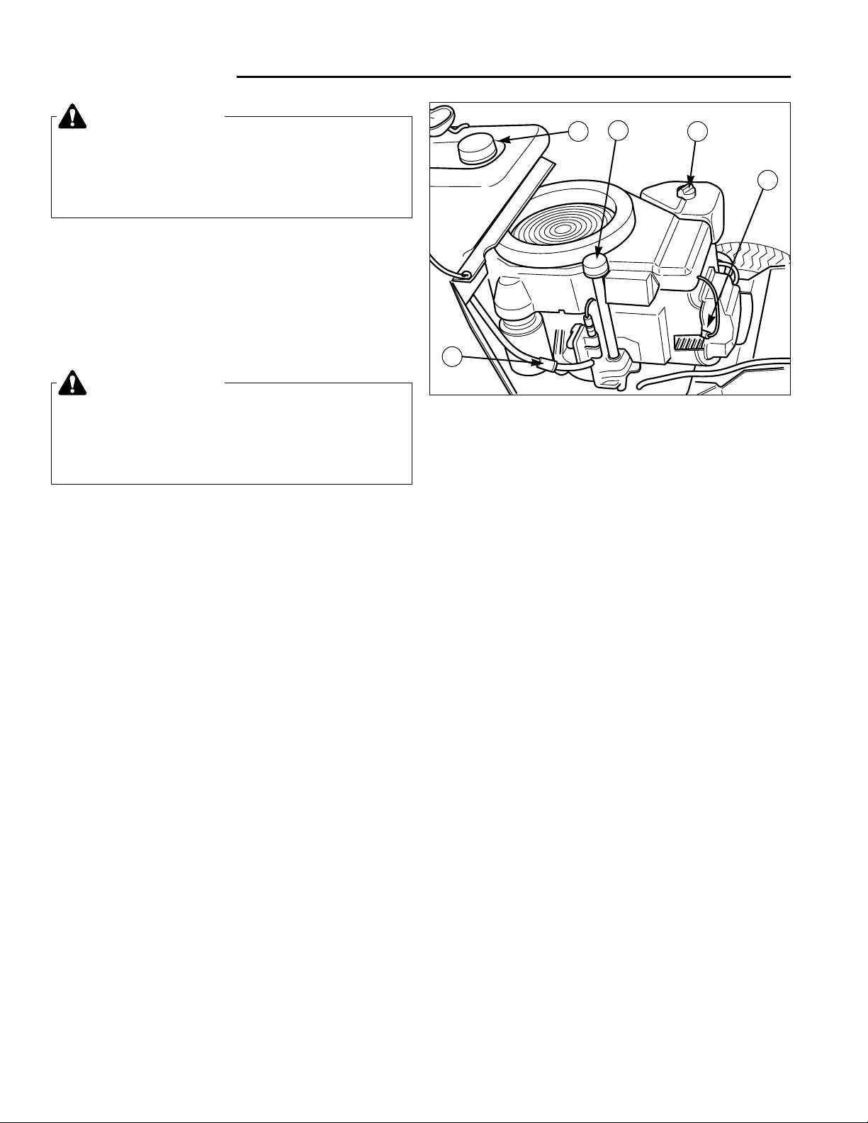
The fuel filter (C, Figure 1) is located in fuel line between
fuel tank and carburetor. If filter is dirty or clogged,
replace as follows. Place a container below filter to catch
spilled gasoline.
1. Using a pliers, open and slide hose clamps from fuel
filter.
2. Remove hoses from filter.
3. Install new filter in proper flow direction in fuel line.
Secure with hose clamps. See warning at beginning
of procedure.
Engine Oil & Filter
Refer to engine manual for specific oil and filter recommendations and oil draining procedures.
Engine oil level must be checked at regular intervals to
ensure that engine oil is maintained at a level that will
provide for adequate lubrication of internal components.
The engine oil filter should be changed in accordance
with the engine manufacturer’s recommendations, which
is generally every 50 hours of operation, or more frequently when operating conditions are hot (over 85°), or
dusty.
The oil filter removes abrasive particles and other contaminants from the oil, keeping it clean for maximum lubrication efficiency, and should only be replaced with the
type of filter recommended by the engine manufacturer.
Figure 1. Typical Engine Compartment
A. Oil Fill D. Air Filter
B. Gas Tank E. Spark Plug
C. Fuel Filter
B
A
D
E
C
Checking and Adding Gasoline
Raise the hood and check the fuel tank to be sure there
is enough gasoline to complete the job. To add gasoline,
remove the gas cap. Do not overfill. Leave room in the
tank for fuel expansion. Refer to your engine manual for
gasoline recommendations. Install and hand tighten the
gas cap.
CAUTION
Never use gasoline containing METHANOL, gasohol containing more than 10% ethanol, gasoline
additives, premium gasoline, or white gas because
engine/fuel system damage could result.
WARNING
Do not remove fuel filter when engine is hot, as
spilled gasoline may ignite. DO NOT spread hose
clamps further than necessary. Ensure clamps
grip hoses firmly over filter after installation.
Check / Change Air Filter
Refer to the engine manual for specific air filter service
intervals and procedures. Refer to Figure 1 for air filter
location.
The engine air filter filters out dust and dirt from the air
intake of the engine, and must be cleaned or replaced
every 25 hours of operation, or more frequently when
operating conditions are dusty.
Replace Spark Plug
Refer to the engine manual for specific spark plug service intervals and replacement procedures. Dirty, worn,
or fouled spark plugs may cause hard starting, rough
engine operation, or loss of power. Refer to Figure 1 for
spark plug location.
To remove the spark plug(s) from the engine for inspection or replacement:
1. Turn the ignition off and remove the key. Allow
engine to cool.
2. Raise the hood and locate the spark plug cable and
boot. Pull the boot off the spark plug.
3. Using a spark plug socket and socket wrench,
remove the spark plug from the engine by turning the
spark plug counter-clockwise.
4. Inspect, clean, re-gap, or replace the spark plug as
required.
5. Reinstall the spark plug. Thread the plug into the
cylinder head by hand, then tighten as instructed by
the engine manufacturer’s manual.
Page 29
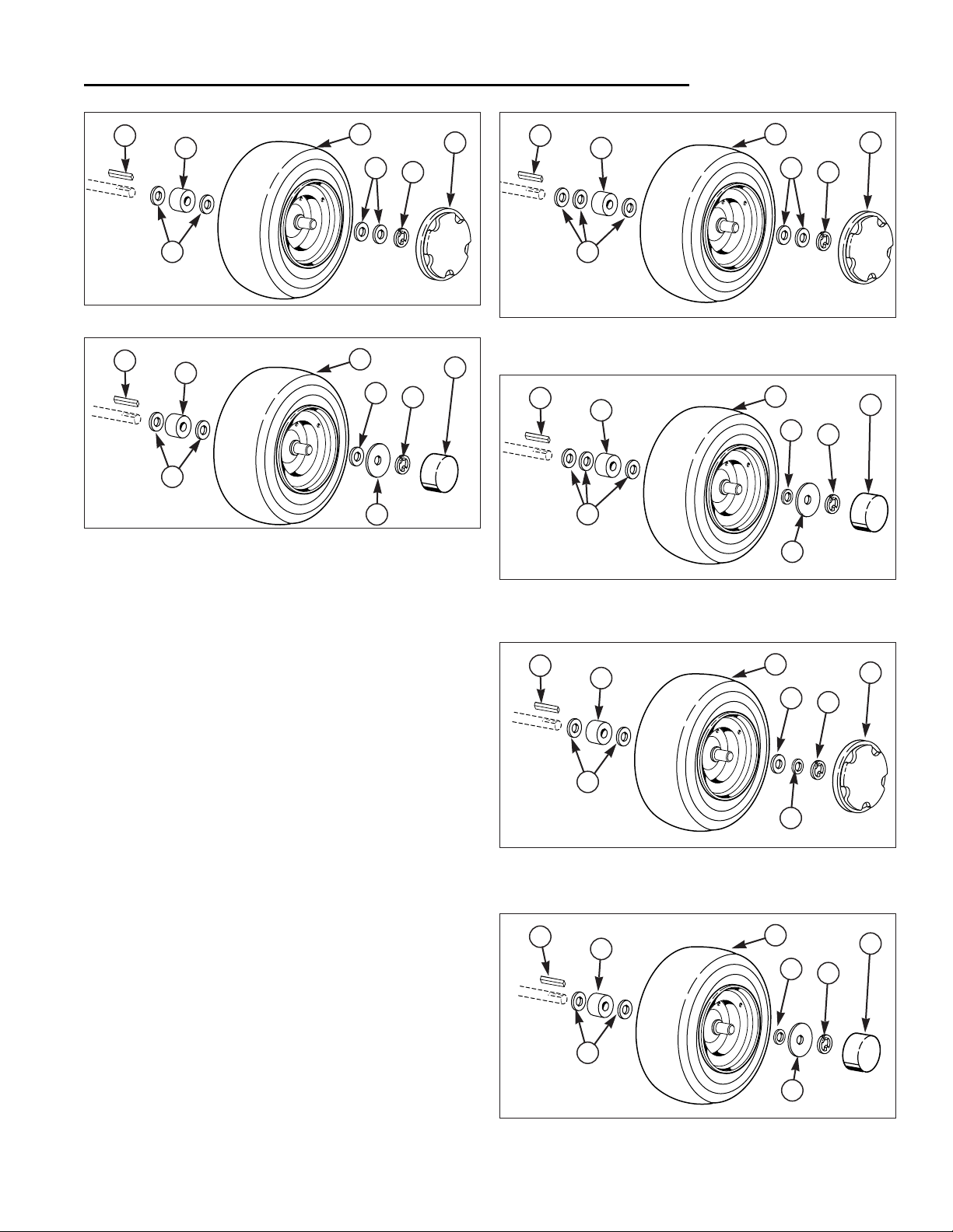
3 - 5
3 Maintenance
Lubricate Rear Axles
Lubricate Rear Axles
We recommend removing the rear wheels and lubricating the axle shafts yearly. This prevents the wheel from
seizing onto the axle shaft and makes future service easier.
Refer to Figures 2-7.
1. Remove the key and disconnect the spark plug wire
while working on the unit.
2. Elevate the rear of the unit. See Section 6.
3. Remove the plastic hub cap (H).
4. Remove e-ring (G) using a screwdriver.
5. Remove the washers (B, E), spacers (C), wheel (D),
and key (A).
NOTE: Your axle assembly may differ slightly from
the assembly pictured: washers may be missing or
doubled. This is adjusted on a tractor by tractor
basis during assembly to allow a small amount of
axle end-play.
6. Lubricate the axle shaft with anti-seize compound or
lithium grease.
7. Reinstall components in reverse order of disassembly
and lower the unit. Be sure the key (A) is in place in
the axle keyway.
A. Key E. Small Washer
B. Large Washer F. Hub Cap Retainer
C. Spacer G. E-Ring
D. Wheel H. Hub Cap
Figure 2. Regent, Tuff Torq K56 Models
A
C
D
H
G
B
B
Figure 4. Regent, Hydro-Gear 0500/0650 Models
A
C
D
H
G
B
Figure 3. 500/2500, Tuff Torq K56 Models
A
F
C
D
H
G
B
B
Figure 5. 500/2500, Hydro-Gear 0500/0650 Models
A
F
C
D
H
G
E
B
B
Figure 6. Regent, Peerless (Gear) Models
A
C
E
D
H
G
B
B
Figure 7. 500/2500, Peerless (Gear) Models
A
F
C
D
H
G
B
E
Page 30
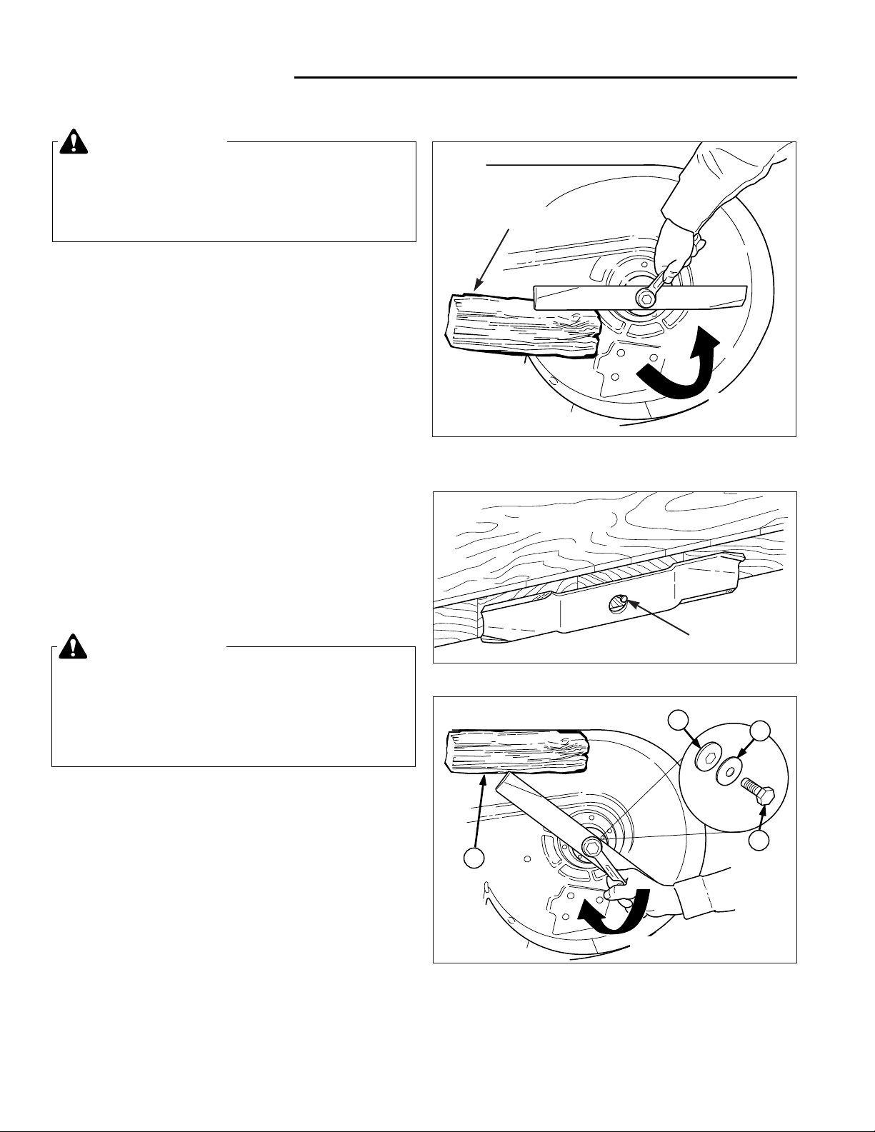
3 Maintenance
Sharpen & Balance Blades
3 - 6
Sharpen & Balance Mower Blades
1. Remove mower from the tractor. See Mower
Installation & Removal.
2. Blades should be sharp and free of nicks and dents.
If not, sharpen blades as described in following steps.
3. To remove blade for sharpening, use a wood block to
hold blade while removing the blade mounting capscrew (Figure 8).
4. Use a file to sharpen blade to fine edge. Remove all
nicks and dents in blade edge. If blade is severely
damaged, it should be replaced.
5. Balance the blade as shown in Figure 9. Center the
blade’s hole on a nail lubricated with a drop of oil. A
balanced blade will remain level.
6. Reinstall each blade with the tabs pointing up toward
deck as shown in Figure 10. Secure with a capscrew,
spring washer and hex washer (be certain the hex
washer is aligned with the hex shaft). Use a wooden
block to prevent blade rotation and torque capscrews
to 50-70 ft.lbs. (67-95 N.m.).
WARNING
For your personal safety, do not handle the sharp
mower blades with bare hands. Careless or
improper handling of blades may result in serious
injury.
WARNING
For your personal safety, blade mounting
capscrews must each be installed with a hex
washer and spring washer, then securely
tightened. Torque blade mounting capscrew to
50 - 70 ft. lbs. (67 - 95 N.m.)
Figure 9. Balancing The Blade
Workbench
Nail
LOOSEN
Figure 8. Removing the Blade
A
D
C
B
TIGHTEN
Figure 10. Installing The Blade
A. 4x4 Wood Block C. Spring Washer
B. Hex Washer D. Blade Bolt
4x4 Wood Block
Page 31

3 - 7
3 Maintenance
Transmission Service
Tuff Torq K-56 Transmission Service
Change the transmission oil after the first 50 hours of
operation and then after every 250 hours. Fill the transmission with SAE 10W-30 motor oil with a minimum API
rating of SG or CD. To change the oil:
ATTENTION: It is critical that dirt and water be kept out
of the transmission. Thoroughly clean and dry all the
surrounding surfaces before opening the transmission.
1. Remove the battery and clean the battery compartment. (See Battery Maintenance).
2. Clean off the fill plug (see Figure 11).
3. Using a screwdriver, pry the fill plug out of the transmission and remove the spring.
4. Remove the drain plugs from the bottom of the transmission case and drain the transmission (Figure 12).
5. Replace the drain plugs and fill the transmission with
oil up to the top notch (see Figure 11 inset).
6. Replace the spring and fill plug. Reinstall the battery.
(See Battery Maintenance).
7. Drive the tractor for several minutes and recheck the
oil level.
Hydro-Gear 0500 / 0650
Transmission Service
The Hydro-Gear 0500 and 0650 hydrostatic drive transmissions do not require regular maintenance. However,
seasonal lubrication of the brake rotor is recommended
(see Figure 20). See your authorized Simplicity Dealer
for transmission service.
Peerless (Gear) Transmission Service
The Peerless MST-205-515A gear drive transmission
uses 80W-90 gear lube and does not require regular
maintenance. See your authorized Tecumseh/Peerless
Dealer for service information.
Figure 12. Draining the Hydro Transmission
Figure 11. Hydo Transmission Fill Plug Location
Drain
Plugs
Fill To
Bottom of
Top Notch
Page 32

3 Maintenance
Battery Maintenance
3 - 8
BATTERY MAINTENANCE
Checking the Battery Fluid
1. Tilt the seat forward to access battery.
2. Remove the battery filler cap (A, Figure 13). Fluid
must be even with the bottom of the split-ring (B). If
not, add distilled water.
3. Reinstall the filler cap.
Cleaning the Battery and Cables
1. Disconnect the cables from the battery, negative
cable first (B, Figure 14).
2. Remove the battery hold-down rods (C, Figure 14)
and battery clamp (D) and battery.
3. Clean the compartment with a solution of baking
soda and water.
4. Clean the battery terminals and cable ends with a
wire brush and battery terminal cleaner until shiny.
5. Reinstall the battery in the battery compartment, and
secure with the battery hold-down rods (C) and battery clamp (D).
6. Reattach the battery cables, positive cable first (see
A, Figure 14)
7. Coat the cable ends and battery terminals with petroleum jelly or non-conducting grease.
WARNING
Be careful when handling the battery. Avoid
spilling electrolyte. Keep flames and sparks away
from the battery.
When removing or installing battery cables,
disconnect the negative cable FIRST and reconnect
it LAST. If not done in this order, the positive
terminal can be shorted to the frame by a tool.
Figure 14. Battery Compartment
A. Positive Battery Terminal
B. Negative Battery Terminal
C. Battery Cap
D. Battery Clamp
C
D
A
B
Figure 13. Check Battery Electrolyte
A. Battery Cap B. Split-Ring
A
B
Page 33

3 - 9
3 Maintenance
Lubrication
Figure 17. Lubricating Tractor - Typical
LUBRICATION
Lubricate the tractor at the locations shown in Figures 15
through 23 as well as the following lubrication points.
Grease:
• steering linkage • mower pivots
• rear axle shafts • mower arbors
• front wheel bushings • foot pedal
Oil:
• front axle assembly • shift linkage
• rear frame assembly pivot • hydro linkage
• seat adjustment assembly • brake linkage
• mower deck height
adjustment linkage
Generally, all moving metal parts should be oiled where
contact is made with other parts. Keep oil and grease off
belts and pulleys. Remember to wipe fittings and surfaces clean both before and after lubrication.
Not all greases are compatible. Simplicity “Jiffy Lube”
Lithium Grease is recommended, automotive-type lithium
grease may be used when this is not available.
*1979
Figure 18. Shift Linkage Lubrication (Gear Model)
Figure 16. Brake Linkage Lubrication - Gear Models
Grease Axle Fittings
- Gear Models
Unit pictured from above with frame removed.
Figure 15. Brake/Hydro Linkage Lubrication
Grease Fitting Located
On Bottom Of Assembly
Page 34

3 Maintenance
Lubrication
3 - 10
Figure 21. Lubricating Mower Deck (38” shown)
Figure 23. Lubricate Deck Linkage (38” shown)
Idler Arm Pivot
Lubrication (Continued).
Figure 22. Front Wheel Bushing Lubrication Grease Fitting Location (Inside hub of wheel). Wheel
shown removed from axle for visual clarity.
Front Wheel
Grease
Fitting
Figure 19. PTO (Electric clutch) The Clutch Anchor
Tab is Covered by A Plastic Cap and Does Not
Require Lubrication. Early Models Not Equipped
with a Plastic Cover Should Be Oiled Yearly
Figure 20. Hydro-Gear 0500 / 0650 Models Only Lubricate the Brake Stators with Spray Lubricant
Spray
Lubricant
Here
Page 35

3 - 11
3 Maintenance
Safety Checks
SAFETY CHECKS
Blade Brake Check
Mower blades and mower drive belt should come to a
complete stop within five seconds after electric PTO
switch is turned off.
1. With tractor in neutral and the PTO disengaged, start
the engine.
2. Look over the left-hand footrest at the mower drive
belt. Engage the PTO and wait several seconds.
Disengage the PTO and check the amount of time it
takes for the mower drive belt to stop.
3. If mower drive belt does not stop within five seconds,
see your dealer.
Safety Interlock System Checks
Your tractor is equipped with a seat switch safety system. Check the seat switch operation every fall and
spring with the following three tests.
Test 1 - Engine should NOT crank if any of
the following conditions exist:
• Transmission is out of neutral.
• PTO switch is engaged.
• Clutch/brake pedal is not fully depressed.
WARNING
If the tractor does not pass the test, do not operate tractor. See your authorized dealer. Under no
circumstance should you attempt to defeat the
purpose of the safety system.
Figure 24. Tractor & Mower Controls - Hydro Model Shown
A. Steering Wheel
B. Throttle
C. Parking Brake Knob
D. Ignition Key/Switch
E. Headlight Switch
F. PTO (Electric Clutch) Switch
G. Mower Height Adjustment Lever
H. Brake Pedal
I. Forward Direction Pedal
J. Rear Direction Pedal
A
H
I
G
F
E
D
C
J
B
Test 2 - Engine should crank if ALL of the
following conditions are met:
• Transmission is in neutral.
• PTO switch is disengaged.
• Clutch/brake pedal is fully depressed.
Test 3 - Engine should shut off if any of the
following conditions exist:
• Operator rises off seat with transmission in gear and
the clutch/brake pedal not fully depressed, and/or the
parking brake is not set.
• Operator rises off seat with clutch/brake pedal not
depressed;
• Operator rises off seat with PTO engaged.
NOTE: Once the engine has stopped, the PTO Switch
(F, Figure 24) must be turned off after operator returns to
the seat in order to start the engine.
Page 36

3 Maintenance
Maintenance Records
3 - 12
Page 37

4 - 1
4 Adjustments
Table of Contents
SECTION CONTENTS
Steering System Adjustment
Steering Gear Adjustment............................................................ 4-2
Brake & Brake Spring Adjustment
Tuff Torq K-56 Models ................................................................. 4-2
Hydro-Gear 0500 / 0650 Models.................................................. 4-3
Peerless Models........................................................................... 4-4
Neutral Adjustment
Tuff Torq K-56 Models ................................................................. 4-5
Hydro-Gear 0500 / 0650 Models.................................................. 4-6
Peerless Models........................................................................... 4-6
Ground Speed Control Foot Pedal Adjustment
Tuff Torq K-56 Models ................................................................. 4-7
Hydro-Gear 0500 / 0650 Models.................................................. 4-7
Mower Adjustments
Adjust Mower Cutting Height & Gauge Wheels ........................... 4-8
Side to Side Leveling ................................................................... 4-8
Front to Back Leveling ................................................................. 4-9
SECTION 4. ADJUSTMENTS
Page 38

4 Adjustments
Steering / Brake Adjustment
4 - 2
STEERING SYSTEM ADJUSTMENT
Steering Gear Adjustment
If there is excessive slack in the steering system, the steering gear backlash can be eliminated by re-indexing the
steering shaft gear using the following adjustment.
1. Loosen the two flange nuts and carriage bolts (A,
Figure 1)
2. Push the steering shaft gear and steering gear
together so that the gear teeth are closely meshed.
3. Retighten the flange nuts (A).
BRAKE & BRAKE SPRING
ADJUSTMENT
Tuff Torq K-56 Models
Note: All brake adjustment is accomplished through
brake spring adjustment.
1. Fully depress brake pedal and lock parking brake.
2. See Figure 2. With the tractor parked on a level surface adjust the brake rod nut (A) until spring (B) is
compressed to a length of 1.69”-1.75” (1-11/16” to 13/4”).
3. Check the adjustment by backing the tractor up a hill,
engaging the parking brake, and shutting off the
engine. While seated in the operator’s position park
the tractor for at least 30 seconds and watch for
movement.
If the parking brake does not hold, tighten the spring.
If the parking brake cannot be engaged, loosen the
brake spring.
WARNING
Before beginning any service work, turn the PTO
off,set the parking brake, turn the ignition switch
off, remove the key, disconnect the spark plug
wire, and disconnect the negative battery cable.
Figure 1. Steering Gear Adjustment
A. Flange Nut & Carriage Bolt
Figure 2. Brake Spring Adjustment -
Tuff Torq K-56 Models
A. Nut B. Spring
A
B
Spring Length
1-11/16” to 1-3/4”
A
Page 39

4 - 3
Brake & Brake Spring Adjustment Hydro-Gear 0500 / 0650 Models
1. Release the parking brake.
2. Place a .025" feeler gauge (A, Figure 3) between the
two outer brake stators (refer to inset illustration).
The gap should be between .025"–.030". To adjust:
a. Remove cotter pin from castellated nut (B) if pre-
sent.
b. To decrease gap, hold feeler gauge in gap and turn
nut (B) clockwise until resistance is felt on the feeler gauge. To increase gap, turn axle nut (B)
counter-clockwise and recheck gap.
c. If cotter pin was removed, back off nut (counter-
clockwise) until the nearest slot is aligned with hole
in threads. Replace cotter pin.
4 Adjustments
Brake Adjustment
2-7/8"-3"
Figure 4. Brake Spring Adjustment
A. Nut B. Spring
B
A
Figure 3. Brake Adjustment (Hydro Model)
A. Feeler Gauge B. Nut
CHECK GAP with .025" FEELER GAUGE
OUTER
BRAKE
OUTSIDE
(Axle)
INSIDE
(Trans.)
INNER
BRAKE
OUTER
STATORS
B
A
Front
3. See Figure 4. Set the parking brake. Loosen or
tighten adjustment nut (A) until spring (B) is compressed to 2-7/8" to 3" length as shown.
Lubricate the
Brake Stators
with Spray
Lubricant
Yearly
Page 40

4 Adjustments
Brake Adjustment
4 - 4
Brake & Brake Spring Adjustment Peerless Models
1. Place the transmission in gear and release the parking brake.
2. See Figure 5. Move the brake lever (B) forward.
There should be a 1/8" (3 mm) gap between the lever
(B) and the stop (C) as shown in the inset.
3. To adjust clearance, turn nut (D) clockwise to
decrease the gap or turn nut counterclockwise to
increase the gap.
Figure 5. Brake Adjustment - Gear Models
A. Brake Rod D. Adjustment Nut
B. Brake Cam Lever E. Spring Adj. Nut
C Stop
A
E
2-3/8" to
2-1/2"
Figure 6. Brake Spring Adjustment - Gear Models
A. Nut B. Spring
B
A
4. See Figure 6. Set the parking brake. Loosen or
tighten adjustment nut (A) to achieve a 2-3/8” to 2
1/2" (60 to 63 mm) compressed spring length as
shown.
Page 41

4 - 5
4 Adjustments
Neutral Adjustment
NEUTRAL ADJUSTMENT
Tuff Torq K-56 Models
The neutral gate of the Tuff Torq K56 is established
internally and should not need to be adjusted. If the tractor creeps forward or backward with the ground speed
control pedal at rest (neutral position) while the engine is
running, perform the following adjustment:
1. Block the front tires.
2. Using an overhead chain hoist or hydraulic floor jack,
elevate the rear end of the tractor so that the wheels
do not contract the ground. Position jackstands
under the rear frame.
3. Remove the clip ring and washer securing the right
rear wheel. Remove the wheel.
4. Using a 17 mm wrench loosen the neutral adjustment
jam nut (A, Figure 7).
5. Activate the seat switch, depress the clutch / brake
pedal, and start the engine.
6. Release the clutch / brake pedal.
6. Using an 8 mm wrench adjust neutral by turning the
eccentric (B, Figure 7).
7. Once neutral has been established, hold the eccentric (B) in place and secure in position with the jam
nut (A).
8. Fully depress the ground speed pedal in both direction and check that it returns to neutral and the rear
wheels do not creep.
9. After adjustments have been completed, shut off the
engine, replace the right rear wheel, and lower the
tractor.
9. Perform GROUND SPEED CONTROL PEDAL
ADJUSTMENT procedure (see Page 4-7).
Figure 7. Neutral Adjustment - Tuff Torq K56
A. Jam Nut B. Eccentric
B
A
WARNING
When making adjustment, keep hands, hair,
clothing, and tools away from rotating belts.
Grasp cam lever at base to keep hand several
inches below belt rotating around idler pulley
assembly. Careless or improper attention may
result in serious injury.
Page 42

4 Adjustments
Neutral Adjustment
4 - 6
Neutral Adjustment Hydro-Gear 0500 / 0650 Models
If the tractor creeps forward or backward with the engine
running and both travel pedals released, perform the following adjustment:
NOTE: For Hydro-Gear 0500 transmission part number
1713761 see Figure 8. For the Hydro-Gear 0650 transmission part number 1715765 see Figure 9. An identification decal is attached to the transmission case.
1. Block the front wheels and raise the rear of the tractor
off the ground with a suitable hoist or floor jack. Install
jack-stands underneath the transaxle.
2. Start the engine and release the parking brake while
keeping seat switch depressed.
3. Loosen the nut (A) securing the neutral adjustment
rod (B). Move the rod until neutral is found, then
retighten the nut.
NOTE: The stop pin (D, Figures 8 and 9) should be positioned near the end of the cam slot when the front pedal
edge is 1/4" above the frame (pedal fully depressed,
Figure 13). If it is not, proceed to the Forward Speed
Adjustment procedure. The stop pin should not “bottom
out” in the cam slot. Increasing the distance between the
end of the cam slot and the stop pin will increase reverse
speed and decrease forward speed.
Figure 8. Neutral Adjustment - Hydro-Gear 0500
A. Nut C. Cam Slot
B. Neutral Adjustment Rod D. Stop Pin
C
D
B
A
Viewed from right side of tractor with rear wheel
removed and foot pedal fully depressed.
C
D
B
A
Gap
Viewed from right side of tractor with rear wheel
removed and foot pedal fully depressed.
Gap
WARNING
When making adjustment, keep hands, hair,
clothing, and tools away from rotating belts.
Grasp cam lever at base to keep hand several
inches below belt rotating around idler pulley
assembly. Careless or improper attention may
result in serious injury.
Neutral Adjustment Peerless (Gear) Models
If the tractor creeps forward or backward with the gear
selector in the neutral gate and the engine running, perform the following adjustment:
1. Release the parking brake. Move the gear selector
until neutral is found and the tractor can be wheeled
freely back and forth.
2. See Figure 10. Raise the seat and loosen the hardware (A) securing the gear selector shaft (B).
3. Place the gear selector shaft in the neutral gate and
retighten the hardware securing shaft.
Figure 10. Neutral Adjustment - Gear Model
A. Hardware B. Shaft
A
B
Figure 9. Neutral Adjustment - Hydro-Gear 0650
A. Nut C. Cam Slot
B. Neutral Adjustment Rod D. Stop Pin
Page 43

4 - 7
4 Adjustments
Ground Speed Control Foot Pedal Adjustment
GROUND SPEED CONTROL
FOOT PEDAL ADJUSTMENT
Tuff Torq K-56 Models
If the unit does not reach top speed with the forward
direction pedal fully depressed, perform the following
adjustment with the engine off and PTO disengaged.
1. Park the tractor on a level surface such as a concrete
floor.
2. Loosen the nut (A, Figure 12) securing the control rod
(B) to the hydro control lever.
3. Place a 2-1/4” thick wood block between the bottom
of the foot pedal and the footrest (see Figure 11).
Hold the pedal against the wood block and tighten
the nut (See A, Figure 12).
NOTE: If a wood block is not available, measure the distance between the bottom of the pedal and the plastic
plug in the footrest. The distance should be 2-1/4” as
shown in Figure 11.
Figure 11. Forward Speed Adjustment - Hydro
A
B
2-1/4”
Unit pictured from above with frame removed.
Figure 12. Hydro Foot Pedal Adjustment
A. Nut B. Control Rod
Hydro-Gear 0500 / 0650 Models
Note: Perform Neutral Adjustment procedure before
adjusting the Forward Speed.
If the unit does not reach top speed with the forward
direction pedal fully depressed, perform the following
adjustment with the engine off and PTO disengaged.
1. See Figure 12. Loosen the nut (A) securing the control rod to the hydro control lever.
2. Position the pedal so the distance between the frame
and bottom edge of the pedal is 1-3/4" as shown in
Figure 13.
3. With pedal in this position, tighten the nut (A, Figure
12).
4. The stop pin (See item D, Figures 8 and 9 under the
NEUTRAL ADJUSTMENT) should be positioned near
the end of the cam slot as shown when the front
pedal edge is 1/4" above the frame (pedal fully
depressed). If it is not, loosen nut (A, Figure 12) and
adjust pedal as necessary, then retighten nut.
NOTE: The stop pin (See item D, Figures 8 and 9 under
the NEUTRAL ADJUSTMENT) should be positioned near
the end of the cam slot when the front pedal edge is 1/4"
above the frame (pedal fully depressed). The stop pin
should not “bottom out” in the cam slot. Increasing the
distance between the end of the cam slot and the stop
pin will increase reverse speed and decrease forward
speed.
Figure 13. Forward Speed Adjustment - Hydro
1-3/4”
Page 44

4 Adjustments
Mower Adjustment
4 - 8
MOWER ADJUSTMENTS
Adjust Mower Cutting Height
& Gauge Wheels
NOTE: Perform adjustment on a hard, level surface such
as a concrete floor.
1. Set the mower height adjustment lever (A, Figure 14)
to the desired cutting height.
2. Remove the pin & clip (B) from each mower deck
front gauge wheel.
3. Adjust the gauge wheels to achieve the appropriate
mower deck-to-ground clearance, as shown in Figure
14. Reinstall pin & clip to each wheel.
Figure 14. Adjusting Mower Deck Gauge Wheels
A. Mower Height Adjustment Lever
B. Pin & Clip
3/4"- 1"with Height Adjuster Lever in lower 3 slots
2" with Height Adjuster Lever in upper 3 slots
A
B
Mower Leveling
If the cut is uneven, the mower may need leveling.
Unequal or improper tire pressure may also cause an
uneven cut. Tire pressure should be as follows:
• Front: 12 - 15 psi (82-103 kPa)
• Rear: 10 - 12 psi (56-82 kPa)
SIDE TO SIDE LEVELING
1. With the mower installed, place the tractor on a
smooth, level surface such as a concrete floor. Turn
the front wheels straight forward.
2. Check for bent blades and replace if necessary.
3. Place the mower in mid-cut position. Arrange the outside mower blades so that they are pointing from
side-to-side (Figure 15).
4. See Figure 15. Measure the distance between the
outside tips of each blade and the ground. If there is
more than 1/8" (3mm) difference between the measurements on each side, proceed to step 5. If the difference is 1/8" (3mm) or less, proceed to Front to
Back Leveling.
5. See Figure 16. Loosen the outside nut (A) and taptite
screw (C), then turn the eccentric nut (B) to raise or
lower the left side of the deck. When the mower deck
is level, hold the eccentric nut while tightening the outside nut. Retighten taptite screw (C).
Figure 15. Leveling the Mower Deck Side-to-Side
Measurement should be within 1/8"
Figure 16. Side-to-Side Adjustment Nut
A. Outside Nut C. Taptite Screw
B. Eccentric Nut
B
A
C
Page 45

4 - 9
4 Adjustments
Mower Adjustment
Figure 17. Leveling the Mower Deck Front-to-Back
Measurement
Tip to Ground
at Front and
Back of Both
Blades
Figure 18. Front-to-Back Adjustment Nut
A. Outside Nut C. Adjustment Nut
B. Eccentric Nut
B
A
C
FRONT TO BACK LEVELING
1. Arrange the blades so they face front-to-back (Figure
17).
2. Measure blade to ground clearance. See Figure 17.
38” Mower Decks: Measure the distance from the
ground to the front and rear tips of each blade. The
measurement should be equal for both blades. Front
tips should be equal to rear tips or within 1/8" higher.
If not, proceed to step 3 below.
44” Mower Decks: Measure the distance from the
ground to the front tip of the front blade and rear tips
of the rear blades. The rear tips should be equal.
The front tip should be equal to rear tips or within 1/4"
higher. If not, proceed to step 3.
3. See Figure 18. Loosen the outside nut (A) and turn
the eccentric nut (B) to raise or lower the rear of the
deck. When the mower deck is level, hold the eccentric nut while tightening the outside nut.
NOTE: If mower handle drops out of cutting height quadrant, turn adjustment nut (C, Figure 18) clockwise to
increase spring tension. DO NOT tighten nut all the way
so that the spring is solid.
Page 46

4 Adjustments
Notes
4 - 10
Page 47

5 - 1
5 Belt Replacement
Table of Contents
SECTION CONTENTS
Tractor Drive Belt Replacement
Belt Removal - Tuff Torq K-56 Models......................................... 5-2
Belt Installation - Tuff Torq K-56 Models...................................... 5-3
Belt Removal - Hydro-Gear 0500 / 0650 Models ......................... 5-4
Belt Installation - Hydro-Gear 0500 / 0650 Models ...................... 5-5
Belt Removal - Peerless (Gear Drive) Models ............................. 5-6
Belt Installation - Peerless (Gear Drive) Models .......................... 5-7
Mower Belt Replacement
38” Mowers .................................................................................. 5-8
44” Mowers .................................................................................. 5-8
SECTION 5. BELT REPLACEMENT
Page 48

5 Belt Replacement
Drive Belt Replacement - Tuff Torq K-56 Models
5 - 2
TRACTOR DRIVE BELT
REPLACEMENT
Belt Removal - Tuff Torq K-56 Models
1. Park the tractor on a level surface. Disengage the
PTO, turn off the engine and set the parking brake.
Remove the key.
2. Remove the mower deck from the tractor. See
MOWER REMOVAL & INSTALLATION, Section 6.
3. Elevate the front of the tractor (see ELEVATING
FRONT END FOR SAFE SERVICE, Section 6).
4. Remove the capscrew (B, Figure 3) securing the right
side of the transmission belt guide (A).
5. Engage the parking brake to slacken the drive belt.
5. Loosen the idler assembly capscrew (D, Figure 2)
and rotate the belt guide (E) away from the belt.
Remove the belt from the idler assembly.
7. Remove the drive belt from the transmission input
pulley (C, Figure 3).
8. Disconnect the drag link (A, Figure 2) from the steering arm (C).
9. Unplug the wiring harness from the PTO clutch (A,
Figure 1) .
10.Remove the capscrew (D) and PTO clutch (A) as
shown in Figure 1.
11.Remove and replace the drive belt.
WARNING
Before beginning any service work, turn the PTO
off,set the parking brake, turn the ignition switch
off, remove the key, disconnect the spark plug
wire, and disconnect the negative battery cable.
Figure 1. PTO Clutch Assembly
A PTO Clutch C. Washer
B. Clutch Anchor D. Capscrew
A
B
C
D
Figure 3. Transmission Belt Guide and Carrier
A. Trans. Belt Guide
B. Right Taptite Screw
C. Transmission Input Pulley
D. Drive Belt
A
B
C
D
Figure 2. Disconnect Drag Link
A. Drag Link
B. Capscrew, Washer, and Nut
C. Steering Arm
D. Idler Assembly Capscrew
E. Belt Guide
A
B
E
C
D
Page 49

5 - 3
5 Belt Replacement
Drive Belt Replacement - Tuff Torq K-56 Models
Figure 4. Drive Belt Routing Hydro-Gear 0500 / 0650 & Tuff Torq K-56 Models
A. Engine Pulley C. Idler Pulley
B. Transmission Pulley
Viewed From Bottom
A
B
C
Belt Installation - Tuff Torq K-56 Models
NOTE: Remove the PTO clutch, disconnect the drag link
from the steering arm, and disconnect the right side of
the transmission belt guide if not already done.
1. Install the new drive belt on the engine crankshaft
drive pulley (A, Figure 4).
2. Using the original hardware, reinstall the PTO clutch
(A, Figure 1). Torque the capscrew (D) to 50 ft. lbs.
3. Reconnect the PTO clutch wire harness.
4. Route the belt through the frame and install it on the
transmission input pulley (C, Figure 3). See Figure 4
for belt routing.
5. Reconnect the drag link (A, Figure 2) to the steering
arm (C) using the original hardware.
6. Engage the parking brake and install the drive belt on
the idler assembly pulleys (see FIgure 2).
7. Release the parking brake and adjust the idler pulley
belt guide (E, Figure 2) 1/4” to 1/8” away from the
belt.
8. Reinstall the capscrew (B, Figure 3) and washer
securing the right side of the belt guide (A).
9. Lower the tractor.
Page 50

5 Belt Replacement
Drive Belt Replacement - Hydro-Gear Models
5 - 4
Figure 6. PTO Clutch Assembly
A PTO Clutch C. Washer
B. Clutch Anchor D. Capscrew
A
B
C
D
Belt Removal Hydro-Gear 0500 / 0650 Models
1. Block the wheels and elevate the front of the tractor
(see ELEVATING FRONT END FOR SAFE SERVICE, Section 6).
2. Remove the mower deck from the tractor. See
MOWER REMOVAL & INSTALLATION, Section 6.
3. Engage the parking brake to slacken the belt.
4. Loosen the front idler pulley belt guide (E, Figure 5)
and remove the drive belt from the idler pulleys (D).
5. Unplug PTO clutch wire harness.
6. Remove the capscrew (D, Figure 6) and remove the
PTO clutch (A).
7. Disconnect the drag link (A, Figure 5) from the steering gear assembly (C).
8. Unhook the transmission belt guide (C) from the carrier hook (D) and pivot it out of the way.
9. Rotate the belt (C, Figure 7) through the fan blades
(A) and off the transmission pulley.
10.Remove and replace the belt.
Figure 5. Disconnect Drag Link
A. Drag Link
B. Capscrew, Washer, and Nut
C. Steering Arm
D. Idler Assembly Pulleys
E. Idler Pulley Capscrew & Belt Guide
A
B
E
C
D
Figure 7. Transmission Belt, Pulley, & Guide
A. Pulley & Fan Assy. C. Belt Guide
B. Belt D. Belt Guide Hook
A
B
C
D
Page 51

5 - 5
5 Belt Replacement
Drive Belt Replacement - Hydro-Gear Models
Figure 9. Drive Belt Routing Hydro-Gear 0500 / 0650 & Tuff Torq K-56 Models
A. Engine Pulley C. Idler Pulley
B. Transmission Pulley
Viewed From Bottom
A
B
C
Belt Installation Hydro-Gear 0500 / 0650 Models
1. Block the wheels and elevate the front of the tractor
(see ELEVATING FRONT END FOR SAFE SERVICE, Section 6).
2. If not done already, unhook the transmission belt
guide (C, Figure 7), unplug and remove the PTO
clutch (A, Figure 6), and disconnect the drag link (A,
Figure 5).
3. Rotate the belt (B, Figure 7) through the transmission
pulley fan (A) and seat it in the pulley groove.
4. Install the belt on the engine pulley (see Figure 9 for
belt routing).
5. Install the PTO clutch as shown in Figure 6. Torque
the capscrew (A) to 50 ft. lbs.
7. Engage the parking brake.
8. Install the belt on the idler pulleys (D, Figure 5).
9. Release the parking brake.
10.Orient the belt guide (E, Figure 5) and tighten the
idler pulley bolt. The belt guide should be 1/4” to 1/8“
away from the belt.
11.Snap the transmission pulley belt guide (C, Figure 7)
into the carrier hook (D).
12.Reattach the drag link (A, Figure 5) to the steering
arm (C).
13.Lower the tractor.
Figure 8. Idler Pulleys
A Rear Idler Pulley
Page 52

5 Belt Replacement
Drive Belt Replacement - Peerless Models
5 - 6
Belt Removal - Peerless (Gear Drive) Models
1. Park the tractor on a level surface. Disengage the
PTO, turn off the engine and set the parking brake.
Remove the key.
2. Remove the mower deck from the tractor. See
MOWER REMOVAL & INSTALLATION, Section 6.
3. Elevate the front of the tractor (see ELEVATING THE
FRONT END FOR SAFE SERVICE, Section 6).
4. Engage the parking brake to slacken the belt.
5. Loosen the idler pulley capscrew and belt guide (E,
Figure 10). Remove the drive belt from the idler
assembly pulleys.
6. Remove the belt from the transmission input pulley
(B, Figure 11) and rear idler pulley (C).
7. Disconnect the upper shift link (A, Figure 12) from the
bell crank (B).
8. Disconnect the steering arm (C, Figure 10) from the
drag link (A).
Figure 11. Idler and Transmission Input Pulleys
A. Drive Belt
B. Transmission Input Pulley
C. Rear Idler Pulley
A
B
C
Figure 12. Peerless Shift Linkage
A. Upper Shift Link
B. Bell Crank Assembly
B
A
Figure 10. Disconnect Drag Link
A. Drag Link
B. Capscrew, Washer, and Nut
C. Steering Arm
D. Idler Assembly Pulleys
E. Idler Pulley Capscrew & Belt Guide
A
B
C
D
E
Page 53

5 - 7
5 Belt Replacement
Drive Belt Replacement - Peerless Models
Figure 13. PTO Clutch Assembly
A PTO Clutch C. Washer
B. Clutch Anchor D. Capscrew
A
B
C
D
Figure 14. Drive Belt Routing - Peerless Models
A. Engine Pulley C. Idler Pulley
B. Transmission Pulley
Viewed From Bottom
A
B
C
9. Unplug the wiring harness from the PTO clutch (A,
Figure 13).
10.Remove the capscrew (D, Figure 13) and remove the
PTO clutch (A).
11.Remove and replace the drive belt.
Belt Installation Peerless (Gear Drive) Models
NOTE: Remove the PTO clutch and disconnect the
upper shift link from the bell crank if not already done.
1. Park the tractor on a level surface. Disengage the
PTO, turn off the engine and set the parking brake.
Remove the key.
2. Remove the mower deck from the tractor. See
MOWER REMOVAL & INSTALLATION, Section 6.
3. Elevate the front of the tractor (see ELEVATING THE
FRONT END FOR SAFE SERVICE, Section 6).
4. Engage the parking brake.
5. Install the new drive belt on the engine pulley (A,
Figure 14) see Figure 14 for belt routing.
6. Reinstall the PTO clutch (A, Figure13). Torque the
capscrew (D) to 50 ft. lbs. Reconnect the PTO clutch
wire harness.
7. Route the belt through the idler pulleys, though the
frame, and onto the transmission input pulley as
shown in Figure 14.
8. Reconnect the steering arm (C, Figure 10) to the
drag link (A) using the original hardware.
9. Reconnect the upper steering link (A, Figure 12) to
the bell crank (B) using the original hardware.
10.Disengage the parking brake and check that the belt
guides do not interfere with the belt. Belt guides
should be adjusted 1/4” to 1/8” away from drive belts.
11.Lower the tractor.
Page 54

5 Belt Replacement
Mower Belt Replacement
5 - 8
MOWER BELT REPLACEMENT
38” Mowers
1. Park the tractor on a level surface. Disengage the
PTO, turn off the engine and set the parking brake.
Remove the key.
2. Remove the mower deck from the tractor. See
MOWER REMOVAL & INSTALLATION, Section 6.
3. Note the position of the idler pulley belt guide (A,
Figure 15) and loosen the pulley capscrew.
4. Loosen the arbor belt guides (B, Figure 15).
5. Remove and replace the drive belt.
6. Tighten the belt guides (A and B, Figure 15).
7. Reinstall the mower deck on the tractor.
44” Mowers
1. Park the tractor on a level surface. Disengage the
PTO, turn off the engine and set the parking brake.
Remove the key.
2. Remove the mower deck from the tractor. See
MOWER REMOVAL & INSTALLATION, Section 6.
3. Remove both the left and right arbor belt covers.
4. Loosen the idler pulley capscrew (A, Figure 16).
5. Remove the old belt and install the new belt over the
pulleys as shown in Figure 16.
6. Tighten the idler pulley capscrew (A, Figure 16).
7. Reinstall both belt covers.
8. Reinstall the mower deck on the tractor.
Figure 15. Mower Deck Belt Routing - 38” Deck
A. Idler Pulley Belt Guide
B. Arbor Belt Guides
Figure 16. Mower Deck Belt Routing - 44” Deck
A. Idler Pulley Capscrew
Belt Covers not
shown for clarity
A
B
B
A
Page 55

6 - 1
6 Common Service Procedures
Table of Contents
SECTION CONTENTS
Mower Deck
Mower Installation & Removal...................................................... 6-2
Mower Blade Removal & Installation ........................................... 6-3
Elevating the Tractor
Elevating Rear End for Safe Service............................................ 6-4
Elevating Front End for Safe Service........................................... 6-4
Rear Wheel Installation & Removal
Rear Wheel Installation & Removal ............................................. 6-5
Front Wheel Service
Front Wheel Removal & Installation............................................. 6-6
Wheel Bearing Replacement ....................................................... 6-6
Battery Service
Disconnecting the Battery Cables................................................ 6-7
Removing & Installing the Battery................................................ 6-7
Checking Battery Voltage............................................................. 6-7
Charging a Completely Discharged Battery................................. 6-8
Jump Starting with an Auxiliary (Booster) Battery........................ 6-8
Purge Air from Transaxle
Hydro-Gear 0500 / 650 & Tuff Torq K-56 Models Only.............. 6-10
Burnishing the Electric PTO Clutch
Burnishing the Electric PTO Clutch............................................ 6-10
SECTION 6. COMMON SERVICE PROCEDURES
Page 56

6 Common Service Procedures
Mower Installation & Removal
6 - 2
MOWER DECK
Mower Installation & Removal
NOTE: Perform mower removal and installation on a
hard, level surface such as a concrete floor.
1. Turn the front wheels of the tractor full left.
2. Place the mower in lowest cutting position.
3. Move lever (C, Figure 2) to release belt tension, then
slide belt off of PTO pulley.
4. Remove clip (A, Figure 1) from right side of rod. Pull
rod (A, Figure 2) out from left side.
5. Disconnect the front hitch by pulling out on the
release rod (A, Figure 3) and lifting the mower hitch
off the tractor hitch. Slide the mower deck out from
under the right side of the tractor.
6. Install the mower in reverse order of removal.
Note: When installing rod (A, Figure 2), turning the front
wheels slightly left or right helps to align the holes.
WARNING
Before beginning any service work, turn the PTO
off,set the parking brake, turn the ignition switch
off, remove the key, disconnect the spark plug
wire, and disconnect the negative battery cable.
Figure 3. Front Hitch
A. Release Rod B. Hitch
A
B
Figure 1. Mower Deck - Right Side
A. Clip C. Height Adjustment
B. Pin & Clip Lever
Figure 2. Mower Deck - Left Side (38” Deck Shown)
A. Rod C. Lever
B. Pin & Clip
A
B
C
C
B
A
Page 57

6 - 3
6 Common Service Procedures
Mower Blade Removal & Installation
Mower Blade Removal & Installation
1. Remove mower from the tractor. See Mower
Installation & Removal.
2. Use a wood block to hold the blade while removing
the blade mounting capscrew (see Figure 4).
3. Reinstall each blade with the tabs pointing up toward
deck as shown in Figure 5. Secure with a capscrew
(D), spring washer (C), and hex washer (B). Be certain the hex washer is aligned with the hex shaft.
Use a wooden block (A) to prevent blade rotation and
torque the capscrew to 45-55 ft.lbs. (61-75 N.m.).
WARNING
For your personal safety, do not handle the sharp
mower blades with bare hands. Careless or
improper handling of blades may result in serious
injury.
WARNING
For your personal safety, blade mounting
capscrews must each be installed with a hex
washer and spring washer, then securely
tightened. Torque blade mounting capscrew to
45-55 ft. lbs. (61 - 75 N.m.)
LOOSEN
Figure 4. Removing the Blade
A
D
C
B
TIGHTEN
Figure 5. Installing The Blade
A. 4x4 Wood Block C. Spring Washer
B. Hex Washer D. Capscrew
4x4 Wood Block
Page 58

6 Common Service Procedures
Elevating Unit for Service
6 - 4
Elevating Rear End for Safe Service
1.Remove the ignition key and disconnect spark plug
wire to prevent accidental starting while working on
the unit.
2.Engage the parking brake and block the front wheels.
3.Using a hydraulic or scissors jack positioned at the
center of the rear frame assembly, carefully jack the
unit up until the rear tires are approximately 1" - 2" off
the ground.
NOTE: For overall unit stability during service, do not
jack rear end higher than required for tire removal.
4. Support the rear of the unit on jackstands positioned
under the rear frame.
Figure 6. Jacking Up the Tractor
Figure 7. Supporting the Rear of the Tractor
Figure 8. Supporting the Front of the Tractor
Elevating Front End for Safe Service
1. Remove the ignition key, and disconnect spark plug
wire to prevent accidental starting while working on
the unit.
2. Engage the parking brake and block the rear wheels.
3. Position a hydraulic or scissors jack under the center
of the front axle and raise the front end up 1” to 2”.
NOTE: For overall unit stability during service, do not
jack front end higher than required for tire removal.
4. Support the tractor by positioning jackstands under
the foot rests or frame.
DANGER
PREVENT SERIOUS INJURY OR
DEATH FROM FALLING UNIT
Always use a properly working lifting device with
a capacity suitable for the weight of the unit
being serviced.
Always use a jack stand to support the unit while
performing service, and chock remaining wheels
to prevent the unit from rolling off the supports.
Never work under or around an elevated unit that
is not properly supported and secured in position with wheel chocks.
ELEVATING THE TRACTOR
Page 59

6 - 5
6 Common Service Procedures
Rear Wheel Installation & Removal
REAR WHEEL INSTALLATION
AND REMOVAL
Refer to Figures 9-14.
1. Remove the key and disconnect the spark plug wire
while working on the unit.
2. Elevate the rear of the unit. See ELEVATING REAR
END FOR SAFE SERVICE.
3. Remove the plastic hub cap (H).
4. Remove e-ring (G) using a screwdriver.
5. Remove the washers (B & E), spacers (C), wheel (D),
and key (A).
NOTE: Your axle assembly may differ slightly from
the assembly pictured: washers may be missing or
doubled. This is adjusted on a tractor by tractor
basis during assembly to allow a small amount of
axle end-play.
6. Lubricate the axle shaft with anti-seize compound or
lithium grease.
7. Reinstall components in reverse order of disassembly
and lower the unit. Be sure the key (A) is in place in
the axle keyway.
A. Key E. Small Washer
B. Large Washer F. Hub Cap Retainer
C. Spacer G. E-Ring
D. Wheel H. Hub Cap
Figure 9. Regent, Tuff Torq K56 Models
A
C
D
H
G
B
B
Figure 11. Regent, Hydro-Gear 0500/0650 Models
A
C
D
H
G
B
Figure 10. 500/2500, Tuff Torq K56 Models
A
F
C
D
H
G
B
B
Figure 12. 500/2500, Hydro-Gear 0500/0650 Models
A
F
C
D
H
G
E
B
B
Figure 13. Regent, Peerless (Gear) Models
A
C
E
D
H
G
B
B
Figure 14. 500/2500, Peerless (Gear) Models
A
F
C
D
H
G
B
E
Page 60

6 Common Service Procedures
Front Wheel Removal / Wheel Bearing Replacement
6 - 6
FRONT WHEELS & TIRES
Simplicity Models
AGCO-Allis &
Massey Ferguson Models
6
2
1
1
3
174
5
7
8
9
7
1 2 Bearing
2 1 Rim
3 1 Grease Zerk
4 1 Valve
5 1 Tire
6 1 Washer
7 1 E-Ring
8 1 Hub Cap (Simplicity Models)
9 1 Hub Cap
(AGCO-Allis & Massey Ferguson Models)
Ref. Qty. Description Ref. Qty. Description
Figure 15. Front Wheel Assembly
FRONT WHEEL SERVICE
Front Wheel Removal & Installation
Refer to Figure 15.
1. Elevate the front of the rider (see ELEVATING
FRONT END FOR SAFE SERVICE, this section)
2. Remove the plastic hub cap (Ref. 8, 9). Remove the
e-ring (Ref. 7) using a screwdriver.
3. Remove the washer (Ref. 6).
4. Remove the wheel assembly (Ref. 2 & 5).
5. Install in reverse order of removal.
Wheel Bearing Replacement
Refer to Figure 15 for assembly.
1. Elevate the front of the rider (see ELEVATING
FRONT END FOR SAFE SERVICE, this section)
2. Remove the front wheel (see FRONT WHEEL
REMOVAL & INSTALLATION, this section).
3. Using a drift and hammer, tap the old bearings
(Ref. 1) out of the rim (Ref. 2).
4. Press the new bearing (Ref. 1) into the rim (Ref. 2)
using an arbor press.
5. Reinstall the front wheel (see FRONT WHEEL
REMOVAL & INSTALLATION, this section).
Page 61

6 - 7
BATTERY SERVICE
Disconnecting the Battery Cables
For many service procedures, disconnecting the negative battery cable is recommended. This prevents accidental starting and accidental short-circuiting of electrical
components. If desired, the positive cable may also be
disconnected; however, for normal service this is not
necessary.
1. Tilt the seat forward to access the battery compartment.
2. Remove the capscrew (E, Figure 17), washer (C),
lockwasher (B), and nut (A) securing the NEGATIVE
(-) battery cable (B, Figure 16).
3. Secure the negative cable away from the negative
battery post.
Removing & Installing the Battery
1. Disconnect the battery cables, negative (-) cable (B,
Figure 16) first. (see previous section).
2. Remove the battery clamp (D, Figure 16).
3. Lift the battery out of the battery compartment.
4. Set the new battery in the battery compartment.
5. Secure the battery using the battery clamp (D,
Figure 6).
6. Connect the red positive (+) battery cable to the positive battery post. Secure using the hardware shown
in Figure 17.
7. Connect the black negative (-) battery cable to the
negative battery post. Secure using the hardware
shown in Figure 17.
Checking Battery Voltage
A voltmeter can be used to determine condition of battery. When the engine is off, the voltmeter shows battery
voltage (normally 12 volts). When the engine is running,
the voltmeter shows the voltage of the charging circuit
(normally is 13 to 14 volts).
Figure 17. Battery Cable Hardware
A. Hex Nut D. Cable
B. Lockwasher E. Capscrew
C. Plain Washer
6 Common Service Procedures
Battery Service
Figure 16. Battery Compartment
A. Positive Battery Terminal C. Battery Cap
B. Negative Battery Terminal D. Battery Clamp
C
D
A
B
WARNING
Be careful when handling the battery. Avoid
spilling electrolyte. Keep flames and sparks away
from the battery.
When removing or installing battery cables,
disconnect the negative cable FIRST and reconnect
it LAST. If not done in this order, the positive
terminal can be shorted to the frame by a tool.
A
B
C
D
E
Figure 18. Check Battery Voltage
A dead battery or one too weak to start the engine may
not mean the battery needs to be replaced. For example,
it may mean that the alternator is not charging the battery properly.
Page 62

6 Common Service Procedures
Battery Charging / Jump Starting
6 - 8
WARNING
Keep open flames and sparks away from the
battery; the gasses coming from it are highly
explosive. Ventilate the battery well during
charging.
WARNING
Do not attempt to charge a frozen battery. Allow
the battery to warm to 60° F (15.5° C) before
placing on charger.
Jump Starting with an
Auxiliary (Booster) Battery
Jump starting is not recommended. However, if it must
be done, follow these directions. Both booster and discharged batteries should be treated carefully when using
jumper cables. Follow the steps below EXACTLY, being
careful not to cause sparks. Refer to Figure 48.
1. Both batteries must be of the same voltage.
2. Position the vehicle with the booster battery adjacent
to the vehicle with the discharged battery so that
booster cables can be connected easily to the batteries in both vehicles. Make certain vehicles do not
touch each other.
3. Wear safety glasses and shield eyes and face from
batteries at all times. Be sure vent caps are tight.
Place damp cloth over vent caps on both batteries.
4. Connect positive (+) cable to positive post of discharged battery (wired to starter or solenoid).
5. Connect the other end of same cable to same post
marked positive (+) on booster battery.
6. Connect the second cable negative (-) to other post
of booster battery.
7. Make final connection on engine block of stalled vehicle away from battery. Do not lean over batteries.
8. Start the engine of the vehicle with the booster battery. Wait a few minutes, then attempt to start the
engine of the vehicle with the discharged battery.
9. If the vehicle does not start after cranking for thirty
seconds, STOP PROCEDURE. More than thirty seconds seldom starts the engine unless some mechanical adjustment is made.
10.After starting, allow the engine to return to idle speed.
Remove the cable connection at the engine or frame.
Then remove the other end of the same cable from
the booster battery.
11.Remove the other cable by disconnecting at the discharged battery first and then disconnect the opposite end from the booster battery.
12.Discard the damp cloths that were placed over the
battery vent caps.
Charging a Completely Discharged Battery
1. Be aware of all the safety precautions you should
observe during the charging operation. If you are
unfamiliar with the use of a battery charger and
hydrometer, have the battery serviced by your dealer.
2. Add water sufficient to cover the plate (fill to the proper level near the end of the charge). If the battery is
extremely cold, allow it to warm before adding water
because the water level will rise as it warms. Also, an
extremely cold battery will not accept a normal
charge until it becomes warm.
3. Always unplug or turn the charger off before attaching or removing the clamp connections.
4. Carefully attach the clamps to the battery in proper
polarity (usually red to [+] positive and black to [-]
negative).
5. While charging, periodically measure the temperature
of the electrolyte. If the temperature exceeds 125° F
(51.6° C), or if violent gassing or spewing of electrolyte occurs, the charging rate must be reduced or
temporarily halted to prevent battery damage.
6. Charge the battery until fully charged (i.e. until the
specific gravity of the electrolyte is 1.250 or higher
and the electrolyte temperature is at least 60° F). The
best method of making certain a battery is fully
charged, but not over charged, is to measure the
specific gravity of a cell once per hour. The battery is
fully charged when the cells are gassing freely at low
charging rate and less than 0.003 change in specific
gravity occurs over a three hour period.
Page 63

6 - 9
6 Common Service Procedures
Jump Starting
WARNING
Any procedure other than the preceding could
result in:
(1) personal injury caused by electrolyte
squirting out the battery vents,
(2) personal injury or property damage due to
battery explosion,
(3) damage to the charging system of the
booster vehicle or of the immobilized
vehicle.
Do not attempt to jump start a vehicle having a
frozen battery because the battery may rupture or
explode. If a frozen battery is suspected, examine
all fill vents on the battery. If ice can be seen or if
the electrolyte fluid cannot be seen, do not
attempt to start with jumper cables as long as the
battery remains frozen.
WARNING
For your personal safety, use extreme care when
jump starting. Never expose battery to open flame
or electric spark – battery action generates
hydrogen gas which is flammable and explosive.
Do not allow battery acid to contact skin, eyes,
fabrics, or painted surfaces. Batteries contain a
sulfuric acid solution which can cause serious
personal injury or property damage.
When removing or installing battery cables, disconnect the negative cable FIRST and reconnect
it LAST. If not done in this order, the positive terminal can be shorted to the frame by a tool.
To avoid engine damage, do not disconnect battery while engine is running. Be sure terminal
connections are tight before starting.
THIS HOOK-UP FOR NEGATIVE GROUND VEHICLES
MAKE CERTAIN VEHICLES DO NOT TOUCH
To
Starter
Switch
To
Starter
Switch
Jumper Cable
Jumper Cable
Discharged
Vehicle
Battery
Starting
Vehicle
Battery
Engine
Block
To Ground
**1582
Figure 19. Battery Jump Starting Diagram
Page 64

6 Common Service Procedures
Purging Air From Transaxle / Burnishing PTO Clutch
6 - 10
BURNISHING THE
ELECTRIC PTO CLUTCH
In order to wear evenly, new PTO clutches need to be
burnished after installation.
1. Select a safe area to operate the mower deck. With
the transmission in neutral, the PTO switch disengaged, the parking brake set, and an operator in the
seat, start the tractor engine. Run the engine at full
throttle.
2. Engage the PTO switch and run the deck for fifteen
seconds. Disengage the PTO switch and wait for the
mower drive belt to stop.
3. Repeat ten times and re-check the mower blade
stopping time. Stopping time should be five seconds
or less.
PURGE AIR FROM TRANSAXLE
(Hydro-Gear 0500 / 0650 &
Tuff Torq K-56 Models Only)
Air may become trapped in the inlet hydraulic filter or
closed loop passages of the hydro transaxle during prolonged storage or transmission service. It is very important for proper operation to release any trapped air that
may cause damage to the internal transaxle parts.
1. Park the tractor on a flat, level surface and block the
tires.
2. Place the hydro release lever in the “PUSH” position
by pulling rearward on the lever. See Figures 20 and
21 for transmission release lever locations.
3. Start the tractor engine and run at a low idle.
4. Fully depress the forward ground speed pedal for five
seconds. Next fully depress the reverse ground
speed control pedal for five seconds.
5. Repeat step 4 three times.
6. Stop the engine.
7. Place the hydro release lever in the “DRIVE” position
by pushing lever fully forward.
8. Start the tractor and drive at least five feet in the forward and reverse directions with full throttle and full
ground speed.
9. Repeat step 8 three times.
8. Check oil level (Tuff Torq models only, see Section 3)
Repeat the above steps if tractor has noisy or erratic
operation, or lack of performance after transmission
warm-up.
Figure 21. Release Lever - Tuff Torq K-56 Models
Release Lever
Figure 20. Release Lever - Hydro-Gear 0500 / 0650
Release lever
Figure 22. PTO Switch
PTO Switch
Page 65

7 - 1
7 Electrical System Service
Table of Contents
SECTION CONTENTS
General Information
Section Contents.......................................................................... 7-2
Introduction .................................................................................. 7-2
Principals of Operation................................................................. 7-2
Checking Out the System ............................................................ 7-3
Exploded View Diagrams
Peerless (1998 and Later) & Tuff Torq K-56 Models ................... 7-4
Peerless (1997 and Earlier) & Hydro-Gear 0500 / 0650 .............. 7-6
Wiring Diagrams
Tuff Torq K-56 Models ................................................................. 7-8
Peerless Models (1998 and Later)............................................... 7-9
Hydro-Gear 0500 / 0650 Models................................................ 7-10
Peerless Models (1997 and Earlier)........................................... 7-11
Linear Circuit Diagrams
Start Position.............................................................................. 7-12
Run Position............................................................................... 7-12
Off Position................................................................................. 7-13
Component Location and Replacement
PTO Switch & Headlight Switch................................................. 7-14
Key Switch ................................................................................. 7-14
PTO Clutch................................................................................. 7-15
Foot Pedal Switches .................................................................. 7-15
Transmission Switch .................................................................. 7-15
Circuit Breaker ........................................................................... 7-15
Solenoid ..................................................................................... 7-15
Seat Switch ............................................................................... 7-16
Battery........................................................................................ 7-16
Fuel Solenoid ............................................................................. 7-16
Ignition Coil (Magneto)............................................................... 7-16
Troubleshooting Flow Chart
Chart .......................................................................................... 7-17
Component Tests
A. Check / Clean Wires & Connectors ....................................... 7-22
B. Check / Clean Ground Cable................................................. 7-22
C. Battery Tests ......................................................................... 7-23
D. Circuit Breaker Test............................................................... 7-24
E. Key Switch Tests ................................................................... 7-24
F. PTO Switch Test.................................................................... 7-26
G. Foot Pedal Switch Tests........................................................ 7-27
H. Transmission Switch Tests.................................................... 7-27
I. Seat Switch Tests ................................................................... 7-28
J. Solenoid Tests........................................................................ 7-28
K. PTO Clutch ............................................................................ 7-30
L. Headlight Test........................................................................ 7-30
M. Headlight Switch Test ........................................................... 7-30
N. Fuel Solenoid Test................................................................. 7-30
O. Voltage Regulator.................................................................. 7-30
P. Alternator ............................................................................... 7-30
SECTION 7. ELECTRICAL SYSTEM SERVICE
Page 66

7 Electrical System Service
General Information
7 - 2
WARNING
Before beginning any service work, turn the PTO
off, set the parking brake, turn the ignition switch
off, remove the key, disconnect the spark plug
wire, and disconnect the negative battery cable.
GENERAL INFORMATION
SECTION CONTENTS
Section 7 has seven sub-sections:
General Information–Contains a general overview of
the electrical system, principles of operation, and definitions of basic electrical terms.
Exploded View Diagrams–Three dimensional illustrations of the electrical system components.
Full Electrical System Wiring Diagram–Schematic of
the electrical system.
Linear Circuit Diagrams–Linear diagram showing electrical current path with the key switch in its three positions.
Component Location and Replacement–Shows the
location of electrical components and explains how to
remove and replace them.
Troubleshooting Flow Chart–Provides an ordered
checklist of component tests to solve common electrical
problems. Includes references to specific component
test procedures.
Component Tests–Testing procedures for specific components.
INTRODUCTION
Tools Needed
• VOM (Volt-Ohm meter, multi-meter, or equivalent)
• Test Light.
• Jumper wires with clips at both ends.
Electrical System Changes
Early and later model Regents may have different electrical components. However, the basic configurations and
troubleshooting procedures given in this section still
apply.
System Description
The tractor has three basic electrical circuits corresponding to the three positions of the key switch: START,
RUN, and OFF.
• START sends battery power to two sub-circuits:
1) sends power to the safety switches (PTO, foot
pedal, and transmission switches). If all safety
switches are closed the solenoid is activated sending
power to the starter.
2) sends power to the fuel solenoid, headlight
circuit, etc.
• RUN sends battery power to two sub-circuits:
1) connects the alternator to the battery through key
switch. The alternator coil feeds power back into the
battery for recharging.
2) sends power to the fuel solenoid, head lights, and
PTO clutch switch.
• OFF grounds the engine ignition coil through the ignition switch, preventing ignition system sparking. The
safety interlock system creates its own “OFF” circuit if
an unsafe situation exists. The safety system
grounds the ignition coil using a combination of:
1) the PTO switch and seat switch
or
2) the brake pedal switch and seat switch
if an operator is not present in the seat.
PRINCIPALS OF OPERATION
Ignition System
When the ignition switch is turned to OFF, the ignition
circuit closes and grounds the ignition coil stopping the
engine by terminating spark.
When the ignition switch is in the RUN position, the ignition circuit is open, allowing the engine to run.
Charging System
While the engine is running, current flows from the alternator to the positive battery post and charges the battery.
The circuit breaker, normally closed, opens if the circuit
is shorted.
Page 67

7 - 3
7 Electrical System Service
General Information
Cranking System
THE CRANKING SYSTEM IS COMPOSED OF:
the ignition switch, the safety interlock switches, the PTO
switch, the solenoid, and the starter.
CRANKING SYSTEM CURRENT PATH:
1. Current travels from the battery through the circuit
breaker, through the ignition switch, through the safety switches and PTO switch, to the solenoid.
2. If all safety conditions are met, the safety interlock
switches allow current to pass through the solenoid,
activating the solenoid.
4. The activated solenoid sends power to the starter,
cranking the engine.
Safety Interlock System
The safety system can be divided into two sub-systems:
1) the Operator Present sub-system and
2) the Safety Starting sub-system.
1) OPERATOR PRESENT SUB-SYSTEM
The operator present sub-system grounds the engine
ignition module (killing the engine) if the operator leaves
the seat with the parking brake disengaged (brake pedal
up) or the PTO engaged.
The operator can leave his/her seat with engine running
ONLY if ALL of the following conditions are met:
Hydro Models
-the PTO disengaged, AND
-the parking brake engaged.
Gear Models
-the PTO disengaged, AND
-the parking brake is engaged.
2) SAFETY STARTING SUB-SYSTEM
The safety starting sub-system will prevent the engine
from cranking if the PTO is ON or the parking brake is
disengaged. On gear models the safety starting system
will also prevent cranking if the ground speed control
lever is out of neutral.
The engine will crank ONLY if ALL of the following conditions are met:
-the PTO is disengaged, AND
-the parking brake is engaged,
-(gear models only) AND the ground speed
control lever is in neutral.
CHECKING OUT THE SYSTEM
General
Both the ignition and charging systems are internal to the
tractor engine. Follow the Troubleshooting Guide,
Section 2, or refer to your engine manual for information.
See an authorized dealer or appropriate service manual
for additional engine troubleshooting information.
Basic Electrical Terms:
“Ground” is the negative battery post or any other con-
ductive part of the frame. For best results, use the negative battery post as ground.
“VOM” is a volt-ohm meter, multi-meter, or equivalent.
“VDC” is volts of direct current or the VOM setting used
to measure DC voltage.
“Ohms” are units of resistance or the VOM setting used
to measure resistance.
“Continuity” is a continuous, unbroken circuit. In this
manual continuity is determined with a VOM set to measure Ohms. Zero Ohms is true continuity. However, due
to contact point corrosion and resistance within wires,
continuity may measure a few Ohms.
“No Continuity” is a broken circuit. In this manual no
continuity is determined with a VOM set to measure
Ohms. No continuity will register as infinite Ohms.
“Battery Voltage” is the approximate voltage output of
the battery. Keep in mind that “battery voltage” tested at
any component will be slightly lower than “battery voltage” tested at the battery terminals due to resistance
within connections and wires.
Page 68

7 Electrical System Service
Exploded View Diagram
7 - 4
To Engine
Harness Plug
To Solenoid
(Black)
To Circuit
Breaker (Red)
To Negative
Battery Post
To Starter
Motor
To Solenoid
(Yellow Gear Models)
To Engine
Ground Connection
To PTO Clutch
To Engine
Ground Bolt
To Solenoid
(Yellow Hydro Models)
Transmission (Neutral)
Safety Switch Gear Models Only
1
2 3 4
5
6
7
8
9
10
11
12
13
14
15
16
17
18
19
20
21
25
22
23
26
27
31
32
33
34
35
36
12
38
39
40
37
30
22
28
29
23
28
29
8
20
24
NOTE: Unless noted otherwise,
use the standard hardware torque
specification chart.
Exploded View Diagram - Peerless (1998 & Later), & Tuff Torq K-56 Models
Peerless (1998 and Later)
& Tuff Torq K-56 Models
Page 69

7 - 5
7 Electrical System Service
Exploded View Diagram
Ref. Qty. Description
1 1 CARRIAGE BOLT, 5/16-18 x 3/4
2 1 CLAMP, Battery
3 1 WASHER, Plain, 5/16
4 1 NUT, Hex, Nylon Lock, 5/16-18
5 1 CAP, Vent, Battery
6 1 BATTERY
7 1 HOSE, Drain
8 2 TUBE, Shrink
9 1 WIRE ASSY., Transmission
10 1 SWITCH, Transmission
11 1 SEAL, O-Ring
12 3 WASHER, 5/8 x 1 x 1/64
13 1 SWITCH, Pedal, N.C., Gray
14 1 SWITCH, Pedal, N.O., Black
15 1 SWITCH, Seat
16 1 WIRE ASSY., Seat Switch
17 1 WIRING HARNESS, Main
18 1 SWITCH, Headlights
19 1 SWITCH, PTO
20 2 CABLE, (Solenoid to Starter & Battery to Ground)
21 1 COVER, Terminal
22 2 LOCKWASHER, 5/16
23 2 NUT, Hex, 5/16-24 NF
24 1 CABLE, Battery, Positive
25 1 BOOT, Insulator
26 2 WASHER, 1/4
27 2 CAPSCREW, Hex Hd., 1/4-20 x 3/4
28 2 LOCKWASHER, 1/4
29 2 NUT, Hex, 1/4-20
30 3 TIE
31 1 SOLENOID
32 1 SCREW, Taptite, 1-20 x 5/8
33 1 CIRCUIT BREAKER
34 1 WIRE ASSY.
35 1 SWITCH, Ignition, 6-Pole
36 1 LOCKWASHER, Internal Tooth, 5/8
37 1 CLIP, Wire
38 1 NUT, Hex, Flange, 5/8-32
39 1 COVER, Ignition
40 2 KEY, Ignition
Peerless (1998 and Later) & Tuff Torq K-56 Models
Page 70

7 Electrical System Service
Exploded View Diagram
7 - 6
1
2
3
4
5
7
8
9
10
10
11
12
15
16
17
18
19
20
21
22
23
24
25
26
27
28
29
30
31
32
33
34
34
35
38
39
36
37
To right rear
engine mtg.
bolt.
(Black & Tan)
To solenoid
(Black & Yellow)
To circuit
breaker
(Red)
(Green & Yellow)
To right rear
engine mtg. bolt
To alternator
To headlight
To headlight
To magneto &
fuel shut-off
(Peerless Models)
To
starter
motor
To clutch
22
21
23
35
6
13
14
To magneto
(Hydro-Gear 0500
/ 0650 Models)
Peerless Models
Only
40
NOTE: Unless noted otherwise,
use the standard hardware torque
specification chart.
Exploded View Diagram - Peerless (1997 & Earlier), & Hydro-Gear 0500/0650 Models
Peerless (1997 and Earlier)
& Hydro-Gear 0500 / 0650 Models
Page 71

7 - 7
7 Electrical System Service
Exploded View Diagram
Ref. Qty. Description
1 1 CARRIAGE BOLT, 5/16-18 x 3/4
2 1 CLAMP, Battery
3 1 WASHER, Plain, 5/16
4 1 NUT, Hex, Nylon Lock, 5/16-18
5 1 CAP, Vent, Battery
6 1 BATTERY
7 1 HOSE, Drain
8 1 SWITCH, Seat
9 1 WIRE ASSY., Seat Switch
10 2 TUBE, Shrink
11 1 WIRE ASSY., Transmission
12 1 SWITCH, Transmission
13 1 SEAL, O-Ring
14 1 WASHER, 5/8
15 1 WIRING HARNESS
16 1 SWITCH, Pedal, N.C., Gray
17 1 SWITCH, Pedal, N.O., Black
18 3 TIE
19 1 CLIP, Wire
20 1 COVER, Terminal
21 2 NUT, Hex, 5/16-24 NF
22 2 LOCKWASHER, 5/16
23 2 CABLE, (Solenoid to Starter & Battery to Ground)
24 1 WIRE ASSY.
25 1 SCREW, Taptite, 1-20 x 5/8
26 1 CIRCUIT BREAKER
27 1 SOLENOID
28 1 SWITCH, Headlights
29 1 SWITCH, PTO
30 1 SWITCH, Ignition, 6-Pole
31 1 NUT, Hex, Flange, 5/8-8
32 1 COVER, Ignition
33 2 KEY, Ignition
34 2 NUT, Hex, 1/4-20
35 2 LOCKWASHER, 1/4
36 1 CABLE, Battery, Positive
37 1 BOOT, Insulator
38 2 WASHER, 1/4
39 2 CAPSCREW, Hex Hd., 1/4-20 x 3/4
40 1 WASHER, Spur
Peerless (1997 and Earlier) & Hydro-Gear 0500 / 0650 Models
Page 72

(BACK OF)
IGNITION
SWITCH
(P/N 1716061)
SPLICE
"C"
SPLICE
"A"
SPLICE "E"
SPLICE
"B"
ALTERNATOR
PTO
ELECTRIC CLUTCH
(P/N 1708536)
FUEL SHUTOFF
SOLENOID
SEAT SWITCH
(UNOCCUPIED)
(P/N 1714771)
HEADLIGHT SWITCH
(P/N 1703799)
HEADLIGHTS
STARTER
BATTERY
(P/N 1685215)
CIRCUIT
BREAKER
(P/N 1665238)
SOLENOID
(P/N 1685290)
MAGNETO
PTO SWITCH
(P/N 1714772)
PEDAL SWITCHES
(w/ PEDAL UP)
RED/WHITE
BLACK/RED
SPLICE
"D"
PURPLE
PURPLE
BLACK
BLACK
BLACK/RED
PURPLE
GREEN
BLACK
BLACK
GRAY
BLACK
BLACK
BLACK
BLACK
YELLOW
YELLOW
RED
TAN
TAN
BLUE
RED
TAN
TAN
RED
RED
BLACK
LIGHT BLUE/RED
GREEN
ORANGE
ORANGE
N.C.
N.C.
N.O.
N.O.
N.O.
N.C .
BLACK
BLACK
BLACK
NOTE: A SHORTING CONNECTOR IS USED
ON THE SEAT SWITCH CONNECTOR.
B
S
IGNITION SWITCH
POSITION
1. OFF
2. RUN
3. START
CIRCUIT MAKE
G & M & A
B & L & A
B & L & S
M
L
G
B
A
S
(P/N 1704379)
(P/N 1714770)
7 Electrical System Service
Wiring Diagram
7 - 8
Tuff Torq K-56 Models
Page 73

7 - 9
7 Electrical System Service
Wiring Diagram
Peerless Models (1998 and Later)
PTO
ELECTRIC CLUTCH
P/N 1708536
MAGNETO
IGNITION SWITCH
POSITION
1. OFF
2. RUN
3. START
CIRCUIT MAKE
G & M & A
B & L & A
B & L & S
A
M
L
G
B
S
FUEL SHUTOFF
SOLENOID
N.O.
N.C.
PEDAL SWITCH
P/N 1714770
PTO SWITCH
P/N 1714772
PEDAL SWITCH
P/N 1704379
(BACK OF)
IGNITION
SWITCH
P/N 1716061
N.C.
TRANSMISSION SWITCH
P/N 1654634
STARTER
B
S
SOLENOID
P/N 1685290
HEADLIGHT
SWITCH
P/N 1703799
BATTERY
P/N 1685290
CIRCUIT
BREAKER
P/N 1665238
N.C.
SEAT SWITCH
(UNOCCUPIED)
P/N 1714771
SPLICE
“A”
SPLICE
“B”
SPLICE
“C”
SPLICE
“D”
ALTERNATOR
LIGHT BLUE/RED
LIGHT BLUE/RED
BLACK/RED
RED/WHITE
RED/WHITE
PURPLE
BLUE
RED / WHITE
BLUE
RED RED
YELLOW BLUE
TAN
RED
RED
RED
TAN
TAN
TAN
BLACK
BLACK
BLACK
BLACK
BLACK
BLACK
BLACK
BLACK
BLACK
GRAY
GRAY
GRAY LIGHT BLUE/RED
BLACK
RED
RED
TAN
YELLOW GREEN
GREEN
GREEN
YELLOW
YELLOW
PURPLE
PURPLE
PURPLE
ORANGE ORANGE
BLACK
PURPLE
(PEDAL UP)
(TRANSMISSION
IN NEUTRAL)
Page 74

7 Electrical System Service
Wiring Diagram
7 - 10
Hydro-Gear 0500 / 0650 Models
(BACK OF)
IGNITION
SWITCH
(P/N 1715017)
SPLICE
"C"
SPLICE
"D"
SPLICE
"A"
SPLICE "E"
SPLICE
"B"
ALTERNATOR
(7 AMP)
PTO
ELECTRIC CLUTCH
(P/N 1708536)
FUEL SHUTOFF
SOLENOID
SEAT SWITCH
(UNOCCUPIED)
(P/N 1714771)
HEADLIGHT SWITCH
(P/N 1703799)
HEADLIGHTS
STARTER
BATTERY
(P/N 1685215)
CIRCUIT
BREAKER
(P/N 1665238)
SOLENOID
(P/N 1685290)
MAGNETO
PTO SWITCH
(P/N 1714772)
PEDAL SWITCHES
(w/ PEDAL UP)
RED/WHITE
RED/WHITE
PURPLE
PURPLE
PURPLE
BLACK
BLACK
BLACK/RED
BLACK/RED
PURPLE
GREEN
BLACK/RED
BLACK
BLACK
GRAY
BLACK
BLACK
BLACK
BLACK
YELLOW
YELLOW
RED
TAN
TAN
BLUE
RED
TAN
TAN
RED
RED
BLACK
LIGHT BLUE/RED
GREEN
ORANGE
ORANGE
N.C.
N.C.
N.O.
N.O.
N.O.
N.C .
BLACK
BLACK
BLACK
NOTE: A SHORTING CONNECTOR IS USED
ON THE SEAT SWITCH CONNECTOR.
B
S
IGNITION SWITCH
POSITION
1. OFF
2. RUN
3. START
CIRCUIT MAKE
G & M
B & L & A
B & L & S
A
M
L
G
B
S
(P/N 1704379)
(P/N 1714770)
Page 75

7 - 11
7 Electrical System Service
Wiring Diagram
Peerless Models (1997 and Earlier)
PTO
ELECTRIC CLUTCH
P/N 1708536
MAGNETO
IGNITION SWITCH
POSITION
1. OFF
2. RUN
3. START
CIRCUIT MAKE
G & M
B & L & A
B & L & S
A
M
LG
B
S
FUEL SHUTOFF
SOLENOID
N.O.
N.C.
PEDAL SWITCH
P/N 1714770
PTO SWITCH
P/N 1714772
PEDAL SWITCH
P/N 1704379
(BACK OF)
IGNITION
SWITCH
P/N 1715017
N.C.
TRANSMISSION SWITCH
P/N 1654634
STARTER
B
S
SOLENOID
P/N 1685290
HEADLIGHT
SWITCH
P/N 1703799
BATTERY
P/N 1685290
CIRCUIT
BREAKER
P/N 1665238
N.C.
SEAT SWITCH
(UNOCCUPIED)
P/N 1714771
SPLICE
“A”
SPLICE
“B”
SPLICE
“C”
SPLICE
“D”
ALTERNATOR (3 AMP)
LIGHT BLUE/RED LIGHT BLUE/RED
BLACK/RED
BLACK/RED
RED/WHITE
RED/WHITE
PURPLE
BLUE BLUE
RED RED
YELLOW BLUE
TAN
RED
RED
RED
TAN
TAN
TAN
BLACK
BLACK
BLACK
BLACK
BLACK
BLACK
BLACK
BLACK
BLACK
GRAY
GRAY
GRAY LIGHT BLUE/RED
BLACK
RED
RED
TAN
YELLOW GREEN
GREEN
GREEN
YELLOW
YELLOW
PURPLE
PURPLE
PURPLE
ORANGE ORANGE
BLACK
PURPLE
(TRANSMISSION
IN NEUTRAL)
(PEDAL UP)
Page 76

7 Electrical System Service
Linear Circuit Diagrams
7 - 12
LINEAR CIRCUIT DIAGRAMS
The following three diagrams show the flow of current
with the key switch in its three positions.
BATTERY
CIRCUIT
BREAKER
A
M
L
G
B
S
PTO SWITCH
(OFF POSITION)
N.O.
N.O.
N.C .
PEDAL SWITCHES
(w/ PEDAL UP)
N.C.
N.O.
(P/N 1704379)
(P/N 1714770)
TRANSMISSION SWITCH
(SHIFT LEVER IN NEUTRAL
PEERLESS MODELS ONLY)
N.C.
SOLENOID
B
S
To Fuel Solenoid,
Head Lights,
PTO Switch/Clutch
KEY SWITCH
(START POSITION)
Start Position
Run Position
Start Position
When the key is turned to the START position current
travels through the circuit breaker to the key switch, and
from there on to the safety switches.
When the PTO switch is turned off, the clutch / brake
pedal is depressed, and the ground speed control lever
is placed in neutral (Peerless models only) the solenoid
receives power.
The solenoid is essentially a large electrically powered
switch. When the small posts of the solenoid receive
power, the internal power switch closes sending power to
the starter motor.
If one of the safety switches is open, the solenoid will not
send power to the starter.
Run Position
When the key is turned to the RUN position (after the
engine has started) the battery, alternator, fuel solenoid,
head lights, and PTO clutch are connected through the
key switch.
This multiple splice supplies alternator power to the battery for charging and to the rest of the tractor electrical
system to run the accessories and PTO clutch.
To Fuel Solenoid
To Alternator/Voltage Regulator -
Power Feeds-Back to Charge Battery,
Power Head Lights & PTO Clutch
A
B
G
S
L
M
KEY SWITCH
(RUN POSITION)
BATTERY
CIRCUIT
BREAKER
To Head Lights
SPLICE
PTO SWITCH
(OFF POSITION)
N.C .
N.O.
N.O.
PTO
ELECTRIC CLUTCH
Page 77

7 - 13
7 Electrical System Service
Linear Circuit Diagrams
N.O.
N.O.
N.C .
PEDAL SWITCHES
(w/ PEDAL UP)
N.C.
N.O.
(P/N 1704379)
(P/N 1714770)
A
M
L
G
B
S
MAGNETO
SPLICE
N.C.
PTO SWITCH
(OFF POSITION)
KEY SWITCH
(OFF POSITION)
SEAT SWITCH
(UNOCCUPIED)
(P/N 1714771
To Alternator
Off Position
Off Position
When the key switch is placed in the off position, the
engine magneto (or ignition coil) is grounded through the
key switch terminating spark.
The alternator is also grounded through the key switch to
prevent current from feeding-back to the fuel shut off
solenoid (if the fuel shut off solenoid receives feed back
current, it may remain open and the engine may backfire).
NOTE: Hydro-Gear 0500 / 0650 models and Peerless
models produced before model year 1998 do not ground
the alternator when the key is in the OFF position.
Notice that the magneto is also spliced into the safety
interlock system.
When an operator is present in the seat, the seat switch
is opened. An open seat switch allows both the parking
brake to be released and the PTO to be engaged without
killing the engine.
If the parking brake is released OR the PTO is engaged
with no operator in the seat, the magneto is grounded
killing the engine.
Page 78

7 Electrical System Service
Component Location & Replacement
7 - 14
COMPONENT LOCATION
AND REPLACEMENT
PTO Switch & Headlight Switch
See Figure 1.
1. Disconnect and secure the negative battery cable.
See DISCONNECTING THE BATTERY CABLES,
Section 6.
2. Remove the plastic cover from the back of the control
panel. The cover snaps into place.
3. Unplug the wire harness from the back of the switch.
4. Squeeze the locking tabs on the back of the switch
and push it out the the control panel.
5. Fully insert the new switch into the control panel.
The switch will lock into place.
6. Connect the wire harness to the back of the switch.
7. Reinstall the cover removed in step 2.
Figure 1. PTO, Headlight, and Key Switch Location
PTO Switch
Headlight
Switch
Key Switch
Key Switch
See Figure 1
1. Disconnect and secure the negative battery cable.
See DISCONNECTING THE BATTERY CABLES,
Section 6.
2. Remove the wire harness from the back of the
switch.
3. Note the orientation of the key and switch body to the
control panel.
4. Remove the large hex nut and washer securing the
switch body.
5. Push the switch back through the control panel
6. Insert the new switch through the control panel.
7. Orient the key and switch body as noted in step 3.
8. Secure the switch using the large washer and hex
nut.
9. Reattach the wire harness.
Page 79

7 - 15
7 Electrical System Service
Component Location & Replacement
PTO Clutch
See Figure 2.
For replacement procedure, see Section 14 PTO
CLUTCH SERVICE.
Foot Pedal Switches
See Figure 2.
1. Disconnect and secure the negative battery cable.
See DISCONNECTING THE BATTERY CABLES,
Section 6.
2. Label and disconnect the wire harness.
3. Squeeze the tabs on the side of the switch while
pushing the switch up through the frame.
4. Insert a new switch through the frame and snap into
place. Reconnect the wire harness.
Transmission Switch
See Figure 3.
1. Disconnect and secure the negative battery cable.
See DISCONNECTING THE BATTERY CABLES,
Section 6.
2. Disconnect the wire harness from the switch terminals.
3. Using a 7/8” socket, turn the switch counterclockwise
to remove from the transmission casing. Remove the
O-ring and shim washer from the switch.
4. Install the gasket on the new switch and thread into
the transmission casing. Reconnect the wire harness.
Circuit Breaker
See Figure 4.
1. Disconnect and secure the negative battery cable.
See DISCONNECTING THE BATTERY CABLES,
Section 6.
2. Disconnect the wires from the terminals.
3. Remove the capscrew securing the body of the circuit
breaker.
4. Install a new circuit breaker and secure using the
capscrew removed in step 3.
5. Reattach the wires disconnected in step 2.
NOTE: The posts are marked “BAT” and AUX.” The
BAT post should be connected to the battery via the
solenoid. The AUX post should be connected to the key
switch.
Solenoid
See Figure 4.
1. Disconnect and secure the negative battery cable.
See DISCONNECTING THE BATTERY CABLES,
Section 6.
2. Disconnect the two large wires and 2 small wires
from the solenoid.
3. Remove the two capscrews securing the solenoid.
4. Install a new solenoid and secure using the capscrews removed in step 3.
Figure 4. Solenoid & Circuit Breaker (Under Seat)
Circuit Breaker
Solenoid
Figure 2. PTO Clutch and Foot Pedal Switch
PTO Clutch
Foot Pedal
Switches
Figure 3. Transmission Switch
Transmission
Switch
5. Reattach the two large wires to the large posts.
NOTE: Either wire may be attached to either post.
6. Reattach the two small wires to the two small posts.
NOTE: Either wire may be attached to either post.
Page 80

7 Electrical System Service
Component Location & Replacement
7 - 16
Seat Switch
See Figure 5
1. Disconnect and secure the negative battery cable.
See DISCONNECTING THE BATTERY CABLES,
Section 6.
2. Remove the seat and slide assembly from the hinge
plate, and separate the seat pan from the slide
assembly (see SEAT REMOVAL, Section 13).
3. Disconnect the wire harness from the seat switch.
4. Push in the three outer tabs (A, Figure 6) and rotate
the switch assembly counterclockwise. The outer
locking tabs (A) will break when pushed in.
5. Remove the switch assembly from the seat pan.
6. Install a new switch in the seat pan. Turn the switch
assembly clockwise to lock into place.
7. Reconnect the wire harness.
Battery
See Figure 5.
Refer to REMOVING AND INSTALLING THE BATTERY,
Section 6.
Figure 5. Seat Switch and Battery
Battery
Seat Switch
Figure 6. Seat Switch Removal
A. Outer Locking Tabs
A
A
A
Fuel Solenoid
See Figure 7.
Refer to the engine manufacturer's manual for specific
information regarding engine component testing and
replacement.
A general testing procedure for the fuel solenoid is provided in the COMPONENT TEST section.
Ignition Coil (Magneto)
Located under the engine air shroud.
Refer to the engine manufacturer's manual for specific
information regarding engine component testing and
replacement.
Figure 7. Fuel Solenoid Location
Fuel
Solenoid
Page 81

7 - 17
7 Electrical System Service
Troubleshooting Flow Chart
TROUBLESHOOTING FLOW CHART
The following chart assumes that there is an actual defective component in the electrical system and that all mechanical and fuel related malfunctions have been fixed. It does not address “operator error” issues and assumes that the
technician has exhausted all common sense solutions to simple problems like loose or unplugged connectors and
bare wires shorting to the frame. Locate the problem you are having, then check all the components in the order listed. Refer to the following COMPONENT TEST section for specific component testing procedures.
Check all wires and connections
Refer to
A. Check / Clean
Wires and Connectors.
Replace damaged wires
or connectors.
Component Tests OK
Component
Fails Test
Check / Test the battery Refer to
C. Battery Tests.
Replace battery
Component Tests OK
Component
Fails Test
Check / clean the battery
cables and ground.
Refer to
B. Clean Ground
Cable & C. Battery Tests.
Clean both ends of the
negative battery cable.
Component Tests OK
Component
Fails Test
Check the circuit breaker. Refer to
D. Circuit Breaker
Test.
Replace circuit breaker.
Component Tests OK
Component
Fails Test
Check the key switch. Refer to
E. Key Switch
Tests.
Replace key switch.
Component Tests OK
Component
Fails Test
Check the PTO switch. Refer to
F. PTO Switch
Test.
Replace PTO switch.
Component Tests OK
Component
Fails Test
Check the Black pedal
switch.
Refer to
G. Foot Pedal
Switch Tests.
Replace the foot pedal
switch.
Component Tests OK
Component
Fails Test
Check the transmission
switch (Peerless models).
Refer to
H. Transmission
Switch Tests.
Replace the transmission
switch.
Component Tests OK
Component
Fails Test
Check the solenoid. Refer to
J. Test Solenoid.
Replace the solenoid.
Component Tests OK
Component
Fails Test
Check the starter. Refer to Engine Manual. Replace the starter.
Done
Component
Fails Test
Engine will not turn over:
Page 82

7 Electrical System Service
Troubleshooting Flow Chart
7 - 18
Check all wires and connections.
Refer to
A. Check / Clean
Wires and Connectors.
Replace damaged wires
or connectors.
Component Tests OK
Component
Fails Test
Check the the key switch. Refer to
E. Key Switch
Tests.
Replace the key switch.
Component Tests OK
Component
Fails Test
Check the PTO switch. Refer to
F. PTO Switch
Test.
Replace the PTO switch.
Component Tests OK
Component
Fails Test
Check the grey pedal
switch.
Refer to
G. Foot Pedal
Switch Tests.
Replace the pedal
switch.
Component Tests OK
Component
Fails Test
Check the seat switch. Refer to
I. Seat Switch Test.
Replace the seat switch.
Component Tests OK
Component
Fails Test
Check the engine ignition
system.
Refer to the Engine Manual. Replace defective com-
ponents.
Done
Component
Fails Test
Check the key switch. Refer to
E. Key Switch
Tests.
Replace the key switch.
Component Tests OK
Component
Fails Test
Check the fuel solenoid. Refer to
N. Fuel Solenoid
Test.
Replace the fuel solenoid.
Done
Component
Fails Test
Engine will turn over but will not start:
Engine runs for a few seconds then dies:
Page 83

7 - 19
7 Electrical System Service
Troubleshooting Flow Chart
Check the grey pedal
switch.
Refer to
G. Foot Pedal
Switch Tests.
Replace the foot pedal
switch.
Component Tests OK
Component
Fails Test
Check the seat switch. Refer to
I. Seat Switch Test.
Replace the seat switch.
Done
Component
Fails Test
Check the PTO switch. Refer to
F. PTO Switch
Test.
Replace the PTO switch.
Component Tests OK
Component
Fails Test
Check the PTO switch. Refer to
F. PTO Switch
Test.
Replace the PTO switch.
Component Tests OK
Component
Fails Test
Check the seat switch. Refer to
I. Seat Switch Test.
Replace the seat switch.
Done
Component
Fails Test
Engine dies when brake pedal released:
Engine dies when PTO engaged:
PTO clutch will not engage:
Check the key switch. Refer to
E. Key Switch
Tests.
Replace the key switch.
Component Tests OK
Component
Fails Test
Check the PTO clutch. Refer to
K. PTO Clutch.
Replace the PTO clutch
assemble.
Done
Component
Fails Test
Page 84

7 Electrical System Service
Troubleshooting Flow Chart
7 - 20
Check wires and connections.
Refer to
A. Clean / Check
Wires & Connections.
Replace damaged wires
or connectors.
Component Tests OK
Component
Fails Test
Check / replace light bulbs. Refer to
L. Headlight Test.
Replace the light bulb.
Component Tests OK
Component
Fails Test
Check headlight switch. Refer to
M. Headlight
Switch Test.
Replace the headlight
switch.
Done
Component
Fails Test
Check battery. Refer to
C. Battery Tests.
Replace the battery.
Component Tests OK
Component
Fails Test
Check circuit breaker. Refer to
D. Circuit Breaker
Test.
Replace the circuit breaker.
Component Tests OK
Component
Fails Test
Check ground. Refer to
B. Check / Clean
Ground Cable.
Clean both ends of the
negative battery cable.
Component Tests OK
Component
Fails Test
Check voltage regulator. Refer to Engine Manual. Replace the defective
engine component(s).
Component Tests OK
Component
Fails Test
Check engine alternator. Refer to Engine Manual. Replace the defective
engine component(s).
Component Tests OK
Component
Fails Test
Check key switch. Refer to
E. Key Switch
Tests.
Replace the key switch.
Done
Component
Fails Test
Headlights will not light:
Battery not charging:
Page 85

7 - 21
7 Electrical System Service
Troubleshooting Flow Chart
Check voltage regulator. Refer to Engine Manual. Replace the defective
engine component(s).
Component Tests OK
Component
Fails Test
Check alternator. Refer to Engine Manual. Replace the defective
engine component(s).
Done
Component
Fails Test
Battery over-charging:
Page 86

7 Electrical System Service
Component Tests - Check Wires / Check Ground
7 - 22
COMPONENT TESTS
The following tests should be used in conjunction with
the this section’s troubleshooting flow chart to efficiently
troubleshoot common electrical problems; however, if a
specific component is suspect, these tests can be used
independently of the flow chart and each other.
Figure 9. Testing Cable Continuity
Figure 8. Typical Wire Harness
WARNING
Before beginning any test,
ALWAYS:
• Disconnect the spark plug wire.
• Block the wheels.
IN MOST CASES:
• Engage the parking brake.
• Turn the PTO switch OFF.
• Turn the key switch OFF.
• Place the ground speed control lever in
NEUTRAL (Peerless models only).
If a test procedure requires a configuration other
than the one listed above, instructions will be
provided in that specific procedure.
Always reset the tractor to the configuration listed above unless told otherwise.
A. Check / Clean Wires and Connectors
1. Check all wires for cracked or worn insulation.
2. Check all connectors, terminals, and receptacles for
loose wires or corrosion (Figure 8). Refer to the
exploded view diagrams for wire harness locations.
B. Check / Clean Ground Cable
1. Disconnect the negative battery cable (See DISCONNECTING THE BATTERY CABLES, Section 6).
2. Disconnect the other end of the negative battery
cable (ground cable) from the engine.
Briggs & Stratton Models:
The ground cable is attached to the right, rear engine
mounting bolt.
Kohler Models:
The ground cable is bolted to the back of the left side
of the engine block.
3. Clean the battery and cable terminals with a wire
brush until the metal is shiny.
4. Using a VOM set to Ohms, test the continuity of the
cable (Figure 9). The VOM should register no more
than 2-3 Ohms.
5. Clean the negative battery post and engine ground
with a wire brush until the metal is shiny.
6. Reattach the negative cable to the engine block and
then the negative battery terminal.
Check for
Loose Wires
Inspect
Insulation
Check for
Corrosion
Page 87

7 - 23
7 Electrical System Service
Battery Tests
C. Battery Tests
GENERAL
If the battery is producing 12 volts and the battery cables
have continuity, the rest of the cranking system can be
systematically tested. However, a full test of the battery
includes cleaning, testing battery charge (hydrometer
test) and testing its ability to deliver current (heavy load
test).
NOTE: Before testing, check the battery for any damage
such as a loose post or cracks. Damaged batteries must
be replaced.
HYDROMETER TEST
1. Remove the vent cap (A, Figure 10). Check each cell
using a hydrometer. Replace the cap when finished.
All cells should have a specific gravity of 1.27 or higher.
If the cells vary by more than . 050 points, charge the
battery and recheck.
If one or more cells reads below 1.265 charge at 5 Amps
checking hourly. If the low cell or cells do not improve
within 3 hours of charging, replace the battery.
CHECK ELECTROLYTE LEVEL
1. Remove the battery vent cap (A, Figure 10) and
make sure the breather holes are open.
2. Check that fluid is even with the bottom of the split
rings (B, Figure 10). If not, fill with distilled water.
Replace vent cap when done.
TEST BATTERY VOLTAGE
1. Test the battery voltage: set VOM to VDC.
2. Place one test probe of the VOM on the battery’s
positive post and one probe on the negative post
(see Figure 11). Note and record the battery voltage
as it will be referenced in later tests.
HEAVY LOAD TEST
1. Follow the load tester manufacturer's instructions;
connect the battery tester to the battery.
2. Discharge the battery under a fixed load at three
times the ampere-hour rating for approximately 15
seconds, then read the terminal voltage.
CLEAN BATTERY
1. Disconnect the battery cables. See DISCONNECTING THE BATTERY CABLES, Section 6.
2. Remove the battery from the battery compartment.
3. Remove dirt and corrosion with a solution of 1 part
baking soda and 7 parts water.
4. Clean the posts with a wire brush until the metal is
shiny.
5. Reinstall battery and coat the terminals with petroleum jelly to prevent corrosion.
Figure 11. Check Battery Voltage
Figure 10. Check Battery Electrolyte
A. Battery Cap B. Split-Ring
A
B
WARNING
Be careful when handling the battery. Avoid
spilling electrolyte. Keep flames and sparks away
from the battery.
When removing or installing battery cables,
disconnect the negative cable FIRST and reconnect
it LAST. If not done in this order, the positive
terminal can be shorted to the frame by a tool.
Page 88

7 Electrical System Service
Circuit Breaker / Key Switch
7 - 24
D. Circuit Breaker Test
The circuit breaker is connected to one of the large posts
of the solenoid along with the positive battery cable.
1. Set the VOM to VDC.
2. With the negative probe, touch ground.
3. Touch the positive probe to one post of the circuit
breaker, and then the other. Both posts should have
close to full battery voltage going to them. If not,
replace the breaker.
4. Set VOM to Ohms.
5. See Figure 12. Disconnect the circuit breaker leads
and probe both circuit breaker terminals. If the VOM
reads 5 Ohms or more, replace the circuit breaker.
Figure 12. Testing the Circuit Breaker
E. Key Switch Tests
At the time of this printing two key switches have been
used in Regent / 500 / 2500 series tractors.
Early Models–with Briggs & Stratton engines: HydroGear 0500 / 0650 models, and Peerless models produced before model year 1998 use the key switch pictured in Figure 13.
Later Models–with Kohler engines: Tuff Torq K-56 models, and Peerless models (1998 and later) use the key
switch pictured in Figure 14.
TEST OFF POSITION
1. Remove the plug from the ignition switch.
2. Remove the ignition switch from the control panel.
3. Set VOM to Ohms.
4. Early Models–See Figure 15. With the key switch in
the OFF position connect test leads to terminals G
and M. The VOM should show continuity.
Later Models–See Figure 16. With the key switch in
the OFF position connect test leads to the following
terminal combinations: G to M, G to A, and M to A.
The VOM should show continuity for these three
combinations.
5. Check all other connection combinations for NO continuity. The combinations tested in step 4 should be
the only combinations that have continuity; all other
connection combinations should have NO continuity.
M
G
IGNITION SWITCH
POSITION
1. OFF
2. RUN
3. START
CIRCUIT MAKE
G & M
B & L & A
B & L & S
A
S
L
B
Figure 13. Early Model Key Switch (Back Side View)
L
S
B
IGNITION SWITCH
POSITION
1. OFF
2. RUN
3. START
CIRCUIT MAKE
G & M & A
B & L & A
B & L & S
M
G
A
Figure 14. Later Model Key Switch (Back Side View)
M
G
OFF
RUN
START
Figure 15. Early Models - Test OFF Position
G
M
OFF
RUN
START
A
Figure 16. Later Models - Test OFF Position
Page 89

7 - 25
7 Electrical System Service
Key Switch Tests
TEST RUN POSITION
1. Remove the plug from the ignition switch.
2. Remove the ignition switch from the control panel.
3. Set VOM to Ohms.
4. Early models see Figure 17, later models see
Figure 18.
With the key switch in the RUN position connect test
leads to the following terminal combinations: B to L,
B to A, and L to A. The VOM should show continuity
for these three combinations.
5. Check all other connection combinations for NO continuity. The combinations tested in step 4 should be
the only combinations that have continuity; all other
connection combinations should have NO continuity.
TEST START POSITION
1. Remove the plug from the ignition switch.
2. Remove the ignition switch from the control panel.
3. Set VOM to Ohms.
4. Early models see Figure 19, later models see
Figure 20.
With the key switch in the START position connect
test leads to the following terminal combinations:
B to L, B to S, and L to S. The VOM should show
continuity for these three combinations.
5. Check all other connection combinations for NO continuity. The combinations tested in step 4 should be
the only combinations that have continuity; all other
connection combinations should have NO continuity.
Replace a switch that does not pass all tests.
6. Reinstall the ignition switch and reattach the plug.
L
B
OFF
RUN
START
A
Figure 17. Early Models - Test RUN Position
B
L
OFF
RUN
START
A
Figure 18. Later Models - Test RUN Position
L
B
OFF
RUN
START
S
Figure 19. Early Models - Test START Position
S
L
OFF
RUN
START
B
Figure 20. Later Models - Test START Position
Page 90

7 Electrical System Service
PTO Switch Test
7 - 26
F. PTO Switch Test
The PTO switch is used in the PTO circuit and both safety interlock circuits: cranking and safety shut off. To
accommodate these circuits, the PTO switch has three
sub-switches all actuated by the pull knob.
The top sub-switch (A, Figure 21) is normally closed,
meaning that with the PTO switch in the OFF position
this sub-switch is closed. Pulling up on the pull knob
opens this switch.
The middle and bottom sub-switches (B and C, Figure
21) are normally open, meaning that with the PTO switch
OFF position these switches are open. Pulling up on the
pull knob closes these switches.
TEST PTO SWITCH
NOTE: You may want to remove the PTO switch from
the control panel for testing. Refer to the COMPONENT
LOCATION AND REPLACEMENT procedures located at
the front of this section.
1. Pull the wire harness off the back of the switch.
2. Place the PTO switch in the OFF position (see
Figure 22).
3. Set VOM to Ohms. Test the top, middle, and bottom
rows of terminals (A, B, and C, Figure 21) for continuity.
The top row should have continuity. The middle and
bottom rows should have no continuity (see
Figure 22).
4. Place the PTO switch in the ON position (see
Figure 23).
5. Set VOM to Ohms. Test the top, middle, and bottom
rows of terminals (A, B, and C Figure 21) for continuity.
The top row should have no continuity. The middle
and bottom rows should have continuity (see
Figure 23).
Replace a switch that does not pass all tests.
PTO SWITCH CIRCUITS
N.O.
N.O.
N.C .
SWITCH TERMINALS
(BACK OF SWITCH)
Figure 21. PTO Switch Terminals
A. Top Sub-Switch Terminals
B. Middle Sub-Switch Terminals
C. Bottom Sub-Switch Terminals
A
B
C
PTO Switch OFF Position
Continuity
No Continuity
No Continuity
Figure 22. Test PTO Switch - OFF Position
PTO Switch ON Position
No Continuity
Continuity
Continuity
Figure 23. Test PTO Switch - ON Position
Page 91

7 - 27
7 Electrical System Service
Foot Pedal / Transmission Switch
G. Foot Pedal Switch Tests
Regent / 500 / 2500 series tractors use two foot pedal
interlock switches (one gray, one black) activated by the
by the brake pedal.
The gray switch is normally closed, meaning that when
the brake pedal is at rest (up, not depressed) the switch
is closed and will conduct current. Depressing the brake
pedal (or switch plunger) opens the switch.
The black switch is normally open, meaning that when
the brake pedal is at rest (up, not depressed) the switch
is open and will not conduct current. Depressing the
brake pedal (or switch plunger closes the switch.
GREY SWITCH TESTS
1. Pull the wire harness off the back of the switch.
2. Set VOM to Ohms. With the brake pedal up (not
depressed) probe the switch terminals. The VOM
should show continuity.
3. Depress the brake pedal and engage the parking
brake.
4. Probe the switch terminals. The VOM should show
no continuity.
BLACK SWITCH TESTS
1. Pull the wire harness off the back of the switch.
2. Set VOM to Ohms. With the brake pedal up (not
depressed) probe the switch terminals. The VOM
should show no continuity.
3. Depress the brake pedal and engage the parking
brake.
4. Probe the switch terminals. The VOM should show
continuity.
Replace a switch that does not pass all tests.
Figure 24. Foot Pedal Switch -
Pedal / Plunger Not Depressed
Gray Switch: Continuity
Black Switch: No Continuity
Figure 25. Foot Pedal Switch -
Pedal / Plunger Depressed
Gray Switch: No Continuity
Black Switch: Continuity
H. Transmission Switch Tests
(Peerless Models Only)
Peerless gear drive model Regent / 500 / 2500 series
tractors use a neutral safety switch that screws into the
transmission case. The switch is normally closed, meaning that when the transmission is in NEUTRAL the switch
is closed and will conduct current. Placing the ground
speed control lever in gear opens the switch.
TEST NEUTRAL SAFETY SWITCH
1. Remove the wire harness plug from the safety switch.
2. Set VOM to Ohms. With the transmission in NEUTRAL probe the switch terminals. The VOM should
show continuity.
3. Place the ground speed control lever in first gear.
4. Probe the switch terminals. The VOM should show
no continuity.
Replace a switch that does not pass all tests.
Figure 26. Test Transmission Switch
Page 92

7 Electrical System Service
Seat Switch / Solenoid Tests
7 - 28
I. Seat Switch Test
The seat switch is a normally closed switch, meaning
that when no one is in the seat, the switch is closed and
will conduct current. Sitting in the seat opens the switch.
SEAT SWITCH TEST
1. Tilt the seat forward and pull the wire harness off the
back of the switch.
2. Set VOM to Ohms. With the switch at rest (no operator pushing down on the seat) probe the switch terminals. The VOM should show continuity.
3. Press down in the middle of the seat to activate the
switch.
4. Probe the switch terminals. The VOM should show
no continuity.
Replace a switch that does not pass all tests.
Figure 27. Test Seat Switch
J. Solenoid Tests
IN-TRACTOR TEST
For this, and all tests, the ground speed control lever
must be in neutral, the parking brake set, and the PTO
switch must be OFF. Unplug and secure the spark plug
wire.
1. Disconnect the yellow wire plug and black wire plug
from the small posts of the solenoid.
2. Connect a jumper lead from one small post to
ground.
3. Connect a jumper lead to the other small post and
then touch it to the positive battery post. The lead
may arch to the battery post–this is normal.
There should be a single audible “click” heard as the
solenoid engages and the engine should turn over. If no
click is heard, proceed to SOLENOID BENCH TEST. If
the solenoid clicks but the starter does not turn the
engine over, check the starter cable and the starter itself.
If the solenoid “clicks” rapidly or repeatedly, recheck the
battery and check all connections for corrosion.
WARNING
The procedure you are about to perform in step 3
will cause the engine to turn over.
Be sure the parking brake is set, the ground
speed control lever is in neutral, the PTO is OFF,
the spark plug wire is disconnected, and the
engine is clear to spin.
Figure 28. Jump Solenoid
To Ground
Touch to Positive
Battery Post
Battery
Page 93

7 - 29
7 Electrical System Service
Solenoid Tests
Figure 31.Testing for Solenoid Short
Figure 32. Testing Solenoid Continuity
SOLENOID BENCH TEST
Replace a solenoid that does not pass all of the following
tests.
1. Label and remove all wires from the solenoid, then
remove the solenoid from the tractor.
2. Set the VOM to Ohms. Probe the small posts of the
solenoid (Figure 29). The VOM should read less
than 10 Ohms.
3. Connect the VOM probes to the large posts (Figure
30). The meter should read no continuity.
4. See Figure 31. Probe the mounting base of the solenoid. Probe one of the small posts and observe the
VOM. Now probe the other small post. The VOM
should read no continuity in both cases.
5. Apply 12 VDC to the two small posts. There should
be an audible click as the solenoid engages.
6. With the solenoid engaged (12 VDC to the small
posts), measure the resistance at the two large posts.
The VOM should read less than 10 ohms (continuity).
Replace a solenoid that does not pass all tests.
Figure 30. Testing Solenoid Short
Figure 29. Testing Solenoid Resistance
+ -
12 VDC
Page 94

7 Electrical System Service
Miscellaneous Component Tests
7 - 30
K. PTO Clutch
Refer to Section 14, PTO CLUTCH SERVICE, for compete PTO clutch testing information and replacement
procedures.
L. Headlight Test
1. Remove the socket (A, Figure 33) and bulb (B) by
twisting the socket counterclockwise and pulling it out
of the bezel (C).
2. Visually inspect the bulb. If the filament is burned
out, replace the bulb.
M. Headlight Switch Test
1. Label and remove the wire harness from the headlight switch terminals.
2. Set the VOM to Ohms.
3. With the switch OFF probe both terminals. The VOM
should read no continuity.
4. Turn the switch to ON. The VOM should read continuity.
N. Fuel Solenoid Test
Refer to the engine manufacturer’s operator’s manual for
information relating to engine components.
NOTE: The fuel shut-off solenoid is located on the bottom of the carburetor float bowl (see Figure 35).
1. Turn the ignition switch from OFF to RUN. There
should be an audible “click” as the shut-off solenoid
opens.
If there is no “click” use a VOM set to VDC. Test the
voltage between the solenoid lead and ground. With
the ignition switch in the RUN position, the lead
should have 12 volts. If not, check the ignition switch
and wiring.
If the solenoid is receiving 12 VDC and is not opening, replace the solenoid.
O. Voltage Regulator
Refer to the engine manufacturer’s operator’s manual for
information relating to engine components.
P. Alternator
Refer to the engine manufacturer’s operator’s manual for
information relating to engine components.
Figure 34. Test Headlight Switch
Figure 33. Check Headlight
A. Socket C. Bezel
B. Light Bulb D. Diffuser
A
B
C
D
Figure 35. Fuel Solenoid Location
Fuel
Solenoid
Page 95

8 - 1
8 Steering Component Service
Table of Contents
SECTION CONTENTS
Steering System Components
Exploded View Diagram............................................................... 8-2
General ........................................................................................ 8-4
Upper Steering System Disassembly
Steering Wheel Removal ............................................................. 8-4
Steering Shaft Removal ............................................................... 8-4
Steering Gear Removal................................................................ 8-5
Upper Steering System Assembly
Steering Gear Installation............................................................. 8-6
Steering Shaft Installation ............................................................ 8-6
Steering Wheel Installation .......................................................... 8-7
Lower Steering System Disassembly
Wheel Removal & Wheel Bearing Replacement.......................... 8-8
Tie Rod Removal ......................................................................... 8-8
Spindle Removal.......................................................................... 8-8
Drag Link Removal....................................................................... 8-9
Lower Steering System Assembly
Drag Link Installation.................................................................... 8-9
Spindle Installation....................................................................... 8-9
Tie Rod Installation ...................................................................... 8-9
SECTION 8. STEERING COMPONENT SERVICE
Page 96

8 Steering Component Service
Steering System Components
8 - 2
2
1
3
4
5
6
7
8
9
10
11
12
13
14
15
16
17
18
19
20
21
22
23
24
25
26
27
28
29
14
18
14
7
16
7
13
7
Steering System Components
- Typical
Figure 1. Steering System - Typical
Page 97

8 - 3
8 Steering Component Service
Steering System Components
Ref. Qty. Description
1 1 STEERING WHEEL ASSY., (Incl. CAP Ref. 2)
2 1 CAP, Steering Wheel
3 1 TUBE, Flex
4 1 PIN, Spring, 5/16 x 2-1/2
5 1 SHAFT ASSY., Steering
6 2 CARRIAGE BOLT, 3/8-16 x 1
7 4 WASHER
8 2 NUT, Flange Lock ,Whiz, 3/8-16
9 1 CAPSCREW, 3/8-16 x 1-1/4
10 1 WASHER
11 1 STEERING GEAR ASSY.
12 1 DRAG LINK
13 3 NUT, Hex, Flange Lock. 3/8-16
14 3 KLIPRING
15 1 ARM, Steering, LH
16 2 WASHER
17 2 SPINDLE ASSY.
18 2 SPACER
19 1 PIN, Cotter, 3/16 x 1-1/4
20 1 TIE ROD
21 1 ARM, Steering, RH
22 2 CARRIAGE BOLT, 3/8-16 x 1-1/4
23 1 CARRIAGE BOLT, 5/16-18 x 1
24 1 SPACER
25 1 NUT, Hex, Flange Lock, 5/16-18
26 2 SCREW, Taptite, 5/16-18 x 3/4
27 1 BUSHING
28 1 BUSHING
29 1 PLATE, Steering, Mounting
Steering System Components
Page 98

8 Steering Component Service
Upper Steering System Disassembly
8 - 4
GENERAL
This section covers tear down and reassembly of the
steering system. For replacement of a specific component follow the tear down procedure as far as required,
then skip ahead to the appropriate reinstallation procedure.
The steering system is broken down into the upper and
lower systems.
The upper system consists of the steering wheel, steering shaft, steering gear, and related components.
The lower steering system is composed of the wheels,
spindles, tie rod, drag link, and related components.
NOTE: Your tractor may differ slightly from the illustrations contained in this section.
UPPER STEERING SYSTEM
DISASSEMBLY
Steering Wheel Removal
1. Using a punch, drive out the roll pin (C, Figure 2).
2. Pull the steering wheel (A) off the shaft (D).
3. Remove the flex collar (B).
Steering Shaft Removal
1. Remove the steering wheel (see previous section).
2. Drain the gas tank. Leave the fuel line disconnected.
3. Remove the two capscrews (H, Figure 3) securing
the sides of the dashboard (D) to the bulkhead (F).
4. Remove the spring clips (G) securing the bottom of
the dashboard to the frame.
5. Remove and discard the plastic panel fastener (C)
from the top center of the dash.
6. Flex the sides of the dashboard out of the way, and
remove the two locknuts (E) securing the gas tank
hold-down (A). Remove the hold-down (A).
7. Remove the gas tank (B).
8. Remove the two capscrews (I) securing the lower
rear of the dashboard (D) to the bulkhead (F).
9. Disconnect the throttle cable from the engine.
10.Remove the dashboard (D).
WARNING
Before beginning any service work, turn the PTO
off,set the parking brake, turn the ignition switch
off, remove the key, disconnect the spark plug
wire, and disconnect the negative battery cable.
Figure 2. Remove Steering Wheel
A. Steering Wheel C. Roll Pin
B. Flex Collar D. Steering Shaft
Figure 3. Remove Gas Tank & Dashboard
A. Gas Tank Hold-Down F. Bulkhead
B. Gas Tank G. Spring Clip
C. Panel Fastener H. Front Capscrews
D. Dashboard I. Back Capscrews
E. Locknut
A
B
C
D
A
B
C
D
E
I
G
G
H
F
Page 99

8 - 5
8 Steering Component Service
Upper Steering System Disassembly
11.Remove the cotter pin (D, Figure 4), washer (E), and
bushing (F) from the steering shaft (C).
12.Remove the four capscrews securing the bulkhead
(F, Figure 3) and remove the bulkhead.
13.Remove the two carriage bolts (P, Figure 4) and
flange locknuts (O) securing the steering mounting
plate (G).
14.Elevate the front of the tractor (see ELEVATING
FRONT END FOR SAFE SERVICE, Section 6).
15.Slide the shaft (C) and mounting plate assembly (G)
out of the tractor.
16.Inspect the shaft and bushings for wear. Replace as
needed.
Steering Gear Removal
Refer to Figure 4.
1. Elevate the front of the tractor (see ELEVATING
FRONT END FOR SAFE SERVICE, Section 6).
2. Loosen the flange locknuts (O, Figure 4) and carriage
bolts (P).
3. Separate the rear of the tie rod (J) from the steering
gear assembly (L) by removing the capscrew (N),
washer (M), and nut (K).
4. Remove the two capscrews (I) securing the steering
gear assembly (L) to the frame.
5. Rotate the steering gear assembly (L) back through
the frame.
6. Remove the steering gear bushing (F). Inspect and
replace if necessary.
A
B
C
D
E
E
F
G
F
F
H
I
J
K
M
L
N
O
P
Q
Figure 4. Steering Shaft Replacement
A. Steering Wheel
B. Flex Collar
C. Steering Shaft
D. Cotter Pin
E. Washer
F. Bushing
G. Mounting Plate
H. Clip ring
I. Capscrew
J. Drag Link
K. Nut
L. Steering Gear Assembly
M. Washer
N. Capscrew
O. Flange Nut
P. Carriage Bolt
Q. Roll Pin
Page 100

8 Steering Component Service
Upper Steering System Assembly
8 - 6
UPPER STEERING
SYSTEM ASSEMBLY
Steering Gear Installation
Refer to Figure 5.
1. Insert the steering gear assembly bushing (F) into the
frame.
2. Insert the steering gear assembly (L) into the frame
and rotate the assembly into place.
3. Insert the steering gear assembly shaft into the bushing (F).
4. Secure the assembly (L) using the original
capscrews (I).
5. Reattach the drag link (J).
6. Reinstall the steering shaft (C, see next procedure).
7. Re-index the steering gear (see STEERING GEAR
ADJUSTMENT, Section 4)
Steering Shaft Installation
1. Lubricate the shaft (C, Figure 5) and bearing contact
points with lithium grease.
2. Elevate the front of the tractor (see ELEVATING
FRONT END FOR SAFE SERVICE, Section 6).
3. Insert the shaft (C, Figure 5), washer (E), bushing
(F), and mounting plate (G) assembly through the
frame.
4. Secure the mounting plate (G, Figure 5) to the frame
using two carriage bolts (P) and flange nuts (O). Do
not tighten the hardware at this time.
5. Install the bulkhead (F, Figure 6) and secure using
four capscrews.
6. Install the dashboard (D, Figure 6) routing steering
shaft through the upper dash.
7. Install the two rear dashboard capscrews (I, Figure 6)
only.
8. Install the upper washer (E, Figure 5), bushing (F),
and cotter pin (D).
A
B
C
D
E
E
F
G
F
F
H
I
J
K
M
L
N
O
P
Q
Figure 5. Steering Shaft Replacement
A. Steering Wheel
B. Flex Collar
C. Steering Shaft
D. Cotter Pin
E. Washer
F. Bushing
G. Mounting Plate
H. Clip ring
I. Capscrew
J. Drag Link
K. Nut
L. Steering Gear Assembly
M. Washer
N. Capscrew
O. Flange Nut
P. Carriage Bolt
Q. Roll Pin
 Loading...