

Page 1

OPERATOR’S
MANUAL
42” Snow Plow/Dozer Blade
(42” Blade), Mfg. NO. 1691520
(Hitch Assembly), Mfg.
1692240
Page 2
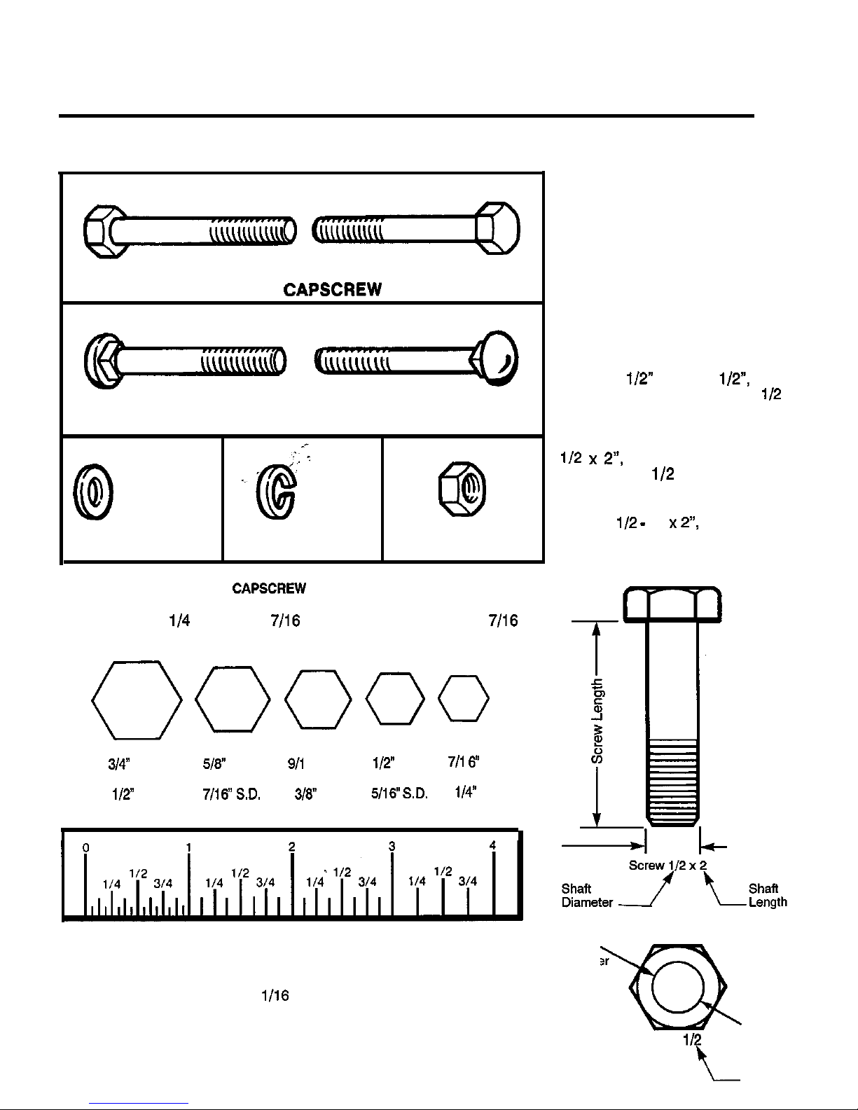
HEX CAPSCREW
CARRIAGE BOLT
PLAIN WASHER
LOCKWASHER
NUT
HEX CAPSCREW IDENTIFICATION
Shown below are actual size heads for standard screw sizes.
Example: a
screw has 7/16 head and thus requires a 7/16
wrench. To measure length, use the scale below.
Head
Head
screw with screw with
Head
screw with
screw with
screw with
S.D.
SD.
WASHER AND NUT IDENTIFICATION
Place the washer or nut on the above scale to
determine the inside diameter. The actual inside
diameter can vary
inch. Use the scale for
comparison.
STANDARD
FASTENER
IDENTIFICATION
CHART
Hardware sizes given in the
illustrations throughout this
manual.
If a washer or nut is identified as
“washer, l/2” or “nut, i/2”, this
means the inside diameter is
inch
If a screw is identified as “screw,
this means the shaft
diameter is
inch and the
shaft of the screw is 2 inches
long. If a screw is identified as
“screw,
16
the number
“16” means that the screw has
16 threads per inch.
SAMPLE: SCREW IDENTIFICATION
Shaft
Diameter
SAMPLE: NUT IDENTIFICATION
Inside
Diameter
Nut.
Inside
Diameter
Page 3
Table of Contents
STANDARD FASTENER IDENTIFICATION CHART
......................................................
Inside
Front
Cover
SAFETY RULES
General
.....................................................................................................................................................
2
Preparation
...............................................................................................................................................
2
Operation
..................................................................................................................................................
2
PARTS ILLUSTRATION ..............................................................................................................................
3
ASSEMBLY. .................................................................................................................................................
4
INSTALLATION.. ..........................................................................................................................................
5
REMOVAL
....................................................................................................................................................
8
OPERATION AND NORMAL CARE
Transporting
..............................................................................................................................................
8
Operation On Slopes
................................................................................................................................
8
Dozing and Snow Plowing ........................................................................................................................
8
Normal Care
..............................................................................................................................................
9
ADJUSTMENTS
Skid Shoes
10
Blade Angle ,.._.__,,,._....,_........................................................................................................................... 10
Spring Tension
TORQUE SPECIFICATIONS
Inside Rear Cover
.
Accessories
For best performance, it is recommended to use tire chains and two (2) rear wheel weights. A
mounted weight box can also be added for addiiional traction. The maximum weight added to the tractor
should not exceed 35 Ibs./wheel plus 100 additional pounds in the rear weight box.
A Snow Cab is available to protect operator from winter weather.
1
Page 4

safety Rules
Read these safety rules and follow them closely. Failure to obey these rules could result in loss of con-
trol of vehicle, severe personal injury to yourself or bystanders, or damage to property or equipment. The
in the text signifies important cautions or warnings which must be followed.
ALL WARNING, CAUTION, and instructional
messages on this attachment and on your
tractor should be carefully read and obeyed. Per-
sonal bodily injury can result when these
GENERAL
*Read the operators manual carefully. Be thor-
oughly familiar with the controls and proper use of
the equipment. Know how to stop the unit and disengage the controls quickly.
*Never allow children to operate the machine. Do
not allow adults to operate it without proper
instruction.
particularly small children and pets.
not carry passengers.
*Make sure:
a. tractor and attachments are in good operating
condition.
b. all safety devices and shields are in place
c. and in good working condition, and
d. all adjustments (skid shoe height, etc.) have
been made.
PREPARATION
*Handle gasoline with care-it is highly flamma-
ble.
a. Use approved gasoline container.
b. Never remove the cap of the fuel tank or add
gasoline to a running or hot engine, or fill the
fuel tank indoors. Wipe up spilled gasoline.
not run the engine indoors. Exhaust fumes are
dangerous.
*Shift into neutral before attempting to start the
engine.
proper footwear. Do not operate tractor
when barefoot or when wearing open sandals or
canvas shoes.
OPERATION
l
Do not allow anyone to use the snow plow/dozer
blade unless they have been instructed on how to
operate it safely.
l
Never attempt to adjust, repair or service the snow
plow/dozer blade while the tractor engine is
running.
not allow others near the snow/dozer blade
while
is being used.
*Use the snow plow/dozer blade only in daylight, or
good artificial light.
*Always lower the snow plow/dozer blade com-
pletely to the ground when leaving it unattended to
prevent it from being accidentally lowered and
causing injury. Make sure blade is locked in
“DOWN” position due to spring-assist.
*Always operate the tractor at reasonable speeds
to prevent the blade from catching an object and
stopping the tractor abruptly.
2
Page 5
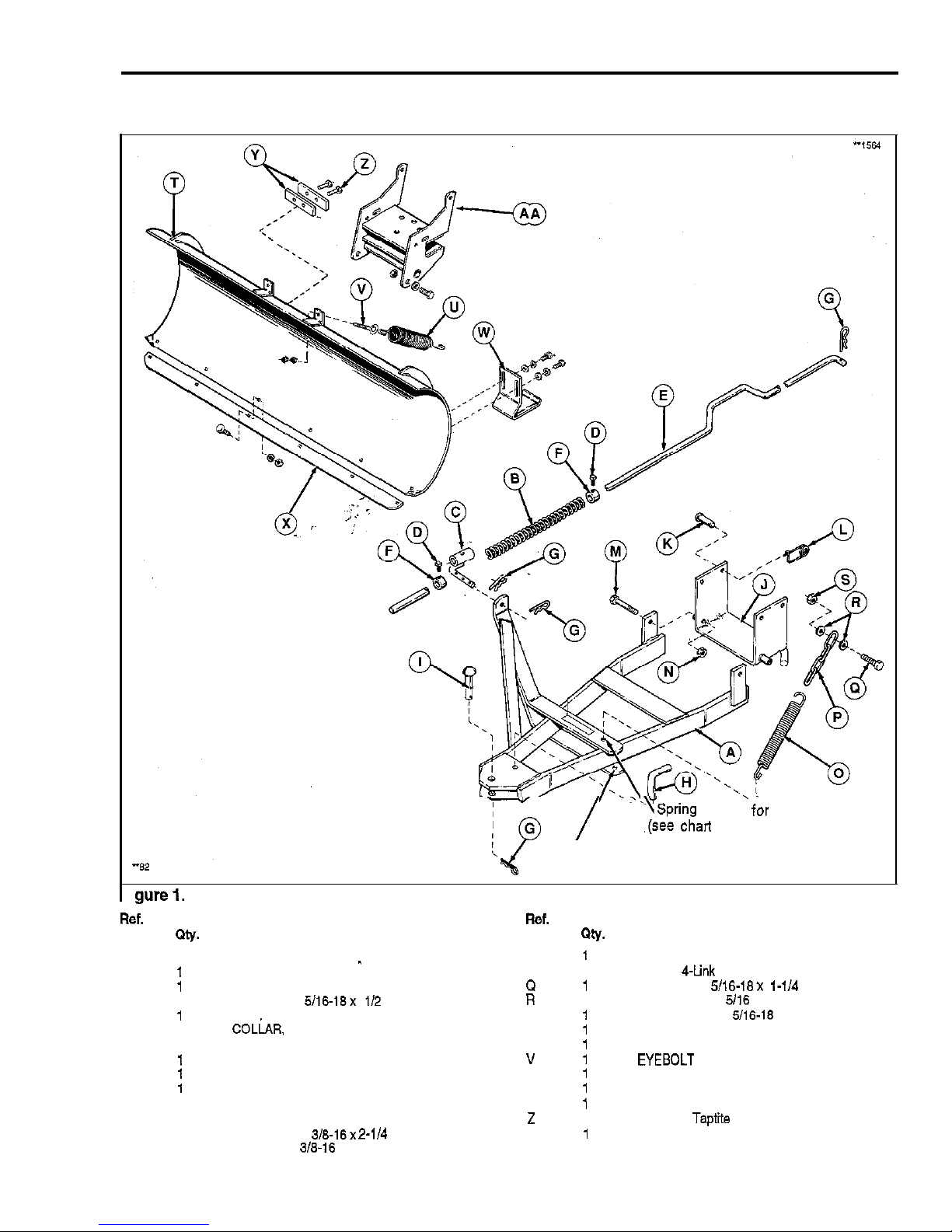
42” Snow Plow/Dozer Blade
PARTS ILLUSTRATION
.ySpring location
garden tractors
chart on page 6).
Spring location for lawn tractors
(see chart on page 6).
NO.
A
1
B
C
D 2
E
F
2
G 4
H
Description
SPRING, Clip
BAR ASSY., Push
PIN, Pivot
SPRING
GUIDE ASSY., Rod
SETSCREW,
ROD. Lift
T
NO.
BLADE
Description
U
0
TRIP ASSY., Spring
SPRING
P
1
CHAIN,
CAPSCREW, 5/16-18x l-114
2 WASHER, Flat,
S
LOCKNUT. Hex.
I 1
PIN, King W
SHOES, Skid (Assembled)
J
BRACKET ASSY. X
PLATE, Wear (Assembled)
K
4
PIN
Y
STOP, Bar
L
4
CLIP, Pin
1
SCREW, Taptite
M
2
CAPSCREW. 3/8-16x
AA
FRAME, Pivot
N 2 LOCKNUT, 318-16
3
Page 6

42” Snow Plow/Dozer Blade
ASSEMBLY
1.
Place the blade on a flat surface.
2. install two bar stops (A, figure 2) using the two
taptite’screws (B).
Figure 2. Bar Stop
A. Bar Stop
B. Taptite Screw,
6-l 8
1
Insert
(A, figure 3)
on blade and
screw on 5/16 nut (B) only far enough
that it is
flush with the end of the
4. Hook the spring (C) into the pivot frame (D).
Stretch the spring with a pliers to hook springs on
eyebok (A).
5. Repeat steps 3 and 4 for the other spring
expose about
(19 mm) of thread.
Hold the
first nut (B) secure with a wrench and tighten the
second nut (E) securely on each
Figure 3. Tension Springs
A.
D. Pivot Frame
0. Nut,
E. Nut,
C. Spring
Page 7

42” Snow Plow/Dozer Blade
8. Assemble the chain (A, figure 4) to the tractor as
follows:
a. On left-hand side, remove the upper self-tapping
screw that holds bumper to frame. This is the hole
used for installing chain in the following steps,
using one 5/16-18x
washers (D), and one
b. Place one 5/16 washer onto the screw. Then place
the chain on the capscrew, and then the other
Insert the capscrew (B, figure 4) as shown. From
inside frame, install
locknut onto capscrew.
Tighten snug only at this time. The spring (C) will
be installed in “Installation” section (step 6), and
hardware will be tightened.
Figure 4. Chain
A. Chain
B.
C. Spring
D. Flat Washer
INSTALLATION
1. Drive the tractor over the push bar until rear of
push bar is under front hitch.
holes in the tractor
with the four pins
and
safety clips (G) provided. Insert the pins from the
outside. Make sure the push bar mounting holes
(in the bracket) are toward the front.
capscrew (H) and 3/8 locknuts
provided.
gure 5. Hitch and Lift Rod
Lift Rod
G. Safety Clip
Front Set Collar
H. Capscrew.
Spring Clip
Spring
I. Locknut,
Rear Set Collar
J. Bracket
Pin
K. Push Bar
Page 8

42” Snow Plow/Dozer Blade
5. Raise the push bar and hook up the spring (A, figure 6) in location
or C as follows:
Location
Tractor (Series)
C
I
6000,800,
I
6. Lower the push bar and tighten the capscrew and
nut which hold chain to tractor frame.
gure 6. Lift-Assist Spring
Spring
Spring Location-Lawn Tractors (See Chart)
Spring Location
Garden Tractors (See Chart)
Page 9

42” Snow Plow/Dozer Blade
7. Insert front of push bar (A, figure 7) into pivot
frame on rear of blade. Then install king pin (C)
down thru holes in
and pivot frame. Secure
king pin (C) with spring clip (D).
8. Using king pin as the pivot, swivel push bar to
align holes for pivot pin (E). Then install pivot pin
downward thru holes in blade and push bar. The
pivot pin can be installed in any of three holes,
depending on desired blade angle.
Figure 7. Dozer Blade Assembled and Installed
A. Push Bar
D. Spring Clip
B. Pivot Frame E. Pivot Pin
C. King Pin
exploded view illustration is shown in figure 1.)
Insert tip of rod guide (A, figure 8) thru hole in lift
arm (B) of push bar. Trap the rod guide on each
side of
arm with spring clips (C and D).
10. Connect rear of lift rod to
lever mounted on
tractor using the spring clip.
Perform adjustments, see page 9.
Figure 8.
A. Rod Guide
B.
Arm (Push Bar)
C. Outer Spring Clip
D. Inner Spring Clip
7
Page 10

42” Snow Plow/Dozer Blade
REMOVAL
Lower the blade,
2. Remove blade and lii rod from push bar.
3. Raise push bar and unhook the spring (A, figure 6)
from the chain.
4. Disconnect the lift rod from the lift lever on tractor
by removing the spring clip.
5. Remove the bracket
figure 5) from the tractor
hitch by removing four pins and safety clips.
6. Reinstall all pins (king pin, pivot pin, clevis pins)
and secure with spring or safety clip for storage.
OPERATION AND NORMAL CARE
Transporting
For maximum ground clearance, transport the blade
to and from work areas fully raised and
straight ahead.
A
WARNING
Be particularly careful and operate at low trac-
tor speeds in any area where the blade can
hook on solid objects. Such objects can
cause the tractor to be jarred or come to an
abrupt stop.
Operation On Slopes
Never operate on slopes greater than 30 percent
(16.7”) which is a rise of 3’ (91 cm) in
forward. Use two rear wheel weights (one per wheel)
when operating on slopes greater than 20 percent
(11.3”).
Always operate up and down the face of slopes, and
never across the face. Use a slow ground speed on
slopes.
Dozing and Snow Plowing
When dozing, push the dirt to the desired location,
then drag the blade backwards for final leveling. Pack
down the dirt or gravel by driving the tractor over the
leveled area.
Use any grade to your advantage. Plow downhill and
set the blade angle
that plowed material (especially snow) is moving downhill as it leaves the blade. For
large
of snow,
off small amounts instead of
plowing a full blade width.
Always use full engine throttle and use the ground
speed control lever to control ground speed and
obtain the needed power to move the material.
Operate at a safe speed, depending on conditions, so
that you have complete control of the tractor. Rear
wheel weights and chains are recommended for slip-
pery surfaces.
8
Page 11

42” Snow Plow/Dozer Blade
Normal Care
After dozing jobs, hose down the blade to remove
excess dirt. Coat bare metal surfaces to prevent rusting. Lightly oil all pivot points.
If the wear plate (A, figure 9) on the bottom of the 42”
blade is worn excessively, replace it
a new one
by removing the six carriage bolts (B), lo&washers
(C) and nuts (D).
ADJUSTMENTS
Lift Rod
For initial setting, place front set collar (A, figure 10)
from rod guide with blade fully lowered. Place rear
set collar (B) against spring (C). Tighten the
setscrews in the two set collars. To adjust, perform
the following:
1. Fully raise the blade by raising on the tractor lift
lever. Measure distance between scraper bar and
ground. If it measures approximately
it is prop
erly adjusted. If not, proceed to step 2.
2. Lower the blade. Loosen the setscrew in the front
set collar. Move the set collar back to increase
clearance or forward to decrease clearance.
Tighten the setscrew. Recheck the measurement.
MOTE:
ground contours may require different adjustments. Lower the blade to adjust rear set
collar. Moving the rear set collar toward rear will allow
the blade to follow a rolling contour. The farther back
the rear set collar is positioned, the more the blade
igure 9.
Wear Plate
. Carriage Bolt,
1
Lockwasher
Figure 10.
A. Front Set Collar
B. Rear Set Collar
C. Spring
9
Page 12

42” Snow Plow/Dozer Blade
Skid Shoes
Alternate holes are provided to permit adjustment of
the shoe assemblies for raising and lowering the
blade to various working heights (see figure 11).
When cleaning snow from gravel or earth drives or
walks the shoe assemblies should be lowered fully to
prevent blade contact with gravel or ground. When
cleaning smooth hard surfaces, like concrete, the
shoe assemblies are normally placed fully up to allow
the blade to scrape the surface.
To adjust the skid, raise the blade off the ground and
block with a piece of wood. Loosen the capscrews (A,
figure 11) and move the skid shoes
desired height. Tighten the capscrews securely.
Blade Angle
To adjust the angle of the blade, proceed as follows:
Lift the blade off the ground using the tractor lift
lever.
2. Remove the pivot pin (H, figure 1 and E, figure
move the blade to desired angle and reinstall the
pivot pin in a diierent hole.
Spring Tension
This snow plow/dozer blade is spring loaded so that
when the blade strikes a solid object, the springs will
allow the blade to release as shown in figure 12 rather
than cause damage. The blade will go back to original
position after object is cleared.
To adjust spring tension, hold rear nut (A, figure 12)
and loosen front nut (B). Tighten rear nut (B) to
increase spring tension or loosen nut to decrease
spring tension. Tighten front nut
are drawn firmly together.
Figure 11. Skid Shoes
A. Capscrews,
B. Skid Shoes
I
Figure 12. Spring Tension
A. Adjustment Nut (Rear)
B. Jam Nut (Front)
10
Page 13

42” Snow Plow/Dozer Blade
NOTES
11
Page 14

42” Snow Plow/Dozer Blade
NOTES
Page 15

TORQUE SPECIFICATIONS FOR
STANDARD MACHINE HARDWARE
TOLERANCE
SEE
SAE GRADE
0
Nm.
Nm.
Nm.
a-32
19 2.1 30 3.4
8-38
20 2.3
3.5
43
4.9
27 3.1 43 4.9
80
8.8
31 3.5 49 5.5
7.7
88 7.8
12
18.3
78 8.8 10 13.8
14
19.
15. 17 23.1
25
34.
12 18.3 19 25.8
25
34.
20 27.2 30 40.8
45
81.2
35 47.8
50
31.3
40.8
50
70
95.2
35 47.8 55 74.8
80
50
75 102.
110 149.8
55 74.8 90 122.4
120
183.2
85
110 149.8
150
204.
75 102. 120 183.2
170 231.2
90 122.4 150 204.
220 299.2
loo 138. 180 244.8
240 328.4
180 217.8 280 353.8
388
525.
180 244.8
420 571.2
140 190.4
800
155 210.8 440
l-a
220 299.2
900
1,224.
1-12
240 328.4 840 870.4
1,000 1,380.
NOTE:
BOLT HEAD MARKING
S.A.E. GRADE:
1. These torque values are to be used for all hardware
excluding: locknuts, self-tapping screws, thread forming
screws, sheet metal screws and socket head setscrews.
2.
a. For prevailing torque locknuts. use 65% of grade
torques.
b. Forflange whizlock nuts (and screws)
use 135%
of grade 5 torques.
3.
Unless otherwise noted on assembly drawings all torque
values must meet this specification.
Page 16

SIMPLICITY MANUFACTURING, INC.SIMPLICITY MANUFACTURING, INC.
FORM 1709932FORM 1709932
500 N. Spring Street500 N. Spring Street PRINTED IN U.S.A.PRINTED IN U.S.A.
Washington, Wi 53074
Washington, Wi 53074
 Loading...