

Simplicity 1692176, 1692175, 1692177, 1692380, 1692382 Service & Repair Manual
...


Section Description Start Page End Page
1 General Information . . . . . . . . . . . . . . . . . . . . . . . . . . 1-1 — 1-14
2 Troubleshooting . . . . . . . . . . . . . . . . . . . . . . . . . . . . . . . 2-1 — 2-4
3 Maintenance. . . . . . . . . . . . . . . . . . . . . . . . . . . . . . . . . . . . 3-1 — 3-10
4 Adjustments. . . . . . . . . . . . . . . . . . . . . . . . . . . . . . . . . . . . 4-1 — 4-8
5 Electrical T roubleshooting. . . . . . . . . . . . . . . . . . . 5-1 — 5-18
6 Wheel Repair. . . . . . . . . . . . . . . . . . . . . . . . . . . . . . . . . . . 6-1 — 6-4
7 Foot Controls Repair . . . . . . . . . . . . . . . . . . . . . . . . . 7-1 — 7-8
8 Hand Controls Repair . . . . . . . . . . . . . . . . . . . . . . . . 8-1 — 8-10
9 Hydro T ransmission Repair . . . . . . . . . . . . . . . . . 9-1 — 9-20
10 Gear T ransmission Repair. . . . . . . . . . . . . . . . . . . 10-1 — 10-8
11 Belt & Clutch Replacement . . . . . . . . . . . . . . . . . 11-1 — 11-6
12 Mower Deck Repair . . . . . . . . . . . . . . . . . . . . . . . . . . . 12-1 — 12-22
Repair Manual Contents
This manual is divided into the sections listed below.
Please see the first page of each section for the specific contents of that section.

1 - 1
1 General Information
Table of Contents
SECTION CONTENTS
Models Covered
Models & Identification................................................................. 1-2
Introduction
Introduction.................................................................................. 1-4
Manual Content ........................................................................... 1-4
Safety Rules
Safety Rules - General Operation................................................ 1-5
Safety Rules - Service And Maintenance .................................... 1-7
General Repair Information
Bearings & Bushings ................................................................. 1-10
Belts & Pulleys........................................................................... 1-10
Electrical Parts........................................................................... 1-10
Fasteners & Hardware............................................................... 1-11
Genuine Replacement Parts...................................................... 1-11
Paint........................................................................................... 1-11
Required Tools & Equipment..................................................... 1-11
Systems Checks........................................................................ 1-11
Specifications..............................................................................1-12
Torque Specifications ................................................................ 1-14
SECTION 1. GENERAL INFORMATION
Mfg. No.
1 General Information
Models Covered In This Manual
1 - 2
MODELS COVERED &
IDENTIFICATION NUMBERS
This manual contains service information for the models
listed below (and similar models produced after this manual’s printing). Consult the Identification Tag located on
the rider frame for the manufacturer’s identification number and serial number.
Always use the manufacturer’s identification number and
serial number when ordering parts or documentation.
Attachments are not covered in this manual. Refer to the
attachment operator’s manual or authorized dealer for
service information.
Transmissions are identified by identification number
tags located on the transmission casing.
1692129 12.5 HP Gear Coronet
1692130 12.5 HP Hydro Coronet
1692166 8.5 HP Gear Coronet
1692168 8.5 HP Gear Coronet
1692175 12 HP Gear 412
1692176 12 HP Gear 412
1692177 9 HP Gear 409
1692380 8.5 HP Gear Coronet
1692382 12.5 HP Gear Coronet
1692385 13 HP Hydro Coronet
1692387 8.5 HP Gear Coronet
1692389 12 HP Gear Coronet
1692392 13 HP Hydro Coronet
1692394 8.5 HP Gear 409
1692396 12 HP Gear 412
1692399 13 HP Hydro 413
1692489 8.5 HP Gear 2400
1692491 13 HP Hydro 2400
1692515 12.5 HP Hydro Coronet
1692517 12 HP Hydro COronet
1692519 12 HP Hydro 412
1692748 11 HP Gear Coronet
1692750 13 HP Hydro Coronet
1692819 11 HP Gear 411
1692821 12 HP Hydro 412
1692823 11 HP Gear 2411
1693030 11 HP Gear Coronet
1693032 11 HP Gear (Export)
1693034 13 HP Hydro Coronet
1693036 13 HP Hydro Coronet (Export)
1693038 14 HP Hydro Coronet
Riders
Description
Description
Mfg. No.
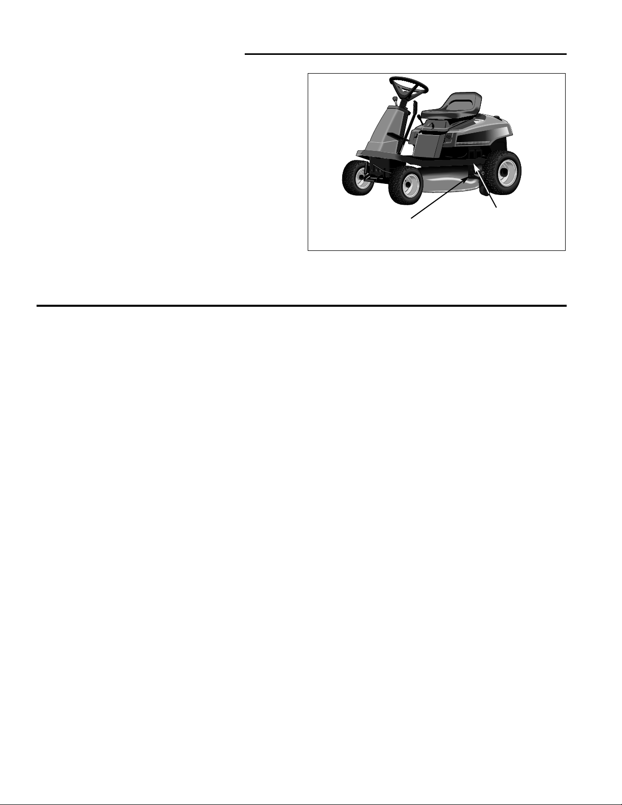
Figure 1. Rider & Mower Identification Tags
Mower
Identification Tag
(Typical Location)
Rider
Identification Tag
(Typical Location)
1693040 14 HP Hydro Coronet (Export)
1693042 11 HP Gear 411
1693044 12 HP Hydro 412
1693046 14 HP Hydro 414
1693048 11 HP Gear 2411
1693050 14 HP Gear 2414
1693303 11 HP Gear Coronet
1693309 11 HP Gear Coronet (Export)
1693315 11 HP Gear 411G
1693319 11 HP Gear 2411G
1694187 11 HP Gear 2411G
1693305 13 HP Hydro Coronet
1693311 13 HP Hydro Coronet (Export)
1693882 13 HP Hydro 413H
1693884 13 HP Hydro 2413H
1694288 13 HP Hydro Coronet
1694289 13 HP Hydro 2413H
1694290 13 HP Hydro 413H
1693307 14 HP Hydro Coronet
1693313 14 HP Hydro Coronet
1693317 14 HP Hydro 414H
1693321 14 HP Hydro 2413H
1694115 16 HP Hydro coronet
1694117 16 HP Hydro 416H
1694189 16 HP Hydro 2416H

1 - 3
1 General Information
Models Covered In This Manual
Mower Decks
1692126 30" Mower
1692127 30" Mower
1692128 34" Mower
1692172 30" Mower
1692173 30" Mower
1692174 34" Mower
1692543 30" Mower
1692544 30" Mower
1692545 34" Mower
1692546 34" Mower
1693168 34” Mower (Export)
1692543 30” Mower
1692544 30” Mower
Mfg. No.
Description
1694053 30” Mower
1692545 34” Mower
1693168 34” Mower (Export)
1692545 34” Mower
1692546 34” Mower
1694191 34: Mower
Mfg. No.
Description

1 General Information
Introduction
1 - 4
INTRODUCTION
This manual is divided into twelve major sections of service information.
1. General Information
Contains general information such as models and manufacturing numbers, general repair instructions for components, and important safety instructions for operating
and servicing the units.
2. Troubleshooting
Provides troubleshooting information pertaining to unit
operation.
3. Maintenance
Contains basic service information for normal maintenance and off-season storage.
4. Adjustments
Contains basic service information and procedures for
adjustments.
5. Electrical Troubleshooting
Contains electrical system troubleshooting procedures.
6. Wheel Repair
Covers wheel removal and repair.
7. Foot Controls Repair
Covers repair of foot controls assemblies.
8. Hand Controls Repair
Covers repair of hand controls assemblies.
9. Hydro Transmission Repair
Covers removal, disassembly, inspection, and repair of
Simplicity serviceable hydro transmissions.
10. Gear Transmission Repair
Covers removal of gear drive transmissions.
11. Belt & Clutch Replacement
Covers belt and clutch removal, installation, and adjustment.
12. Mower Deck Repair
Covers common mower deck service procedures.
Since part numbers are subject to change and may vary
by model year and manufacturing number, all parts in
this manual are referred to by general description.
Specific part number information may be found in the
respective Parts Manual for the unit being serviced.
Always use the manufacturing number that appears on
the Identification Tag of the unit you are servicing to
identify component part numbers.
MANUAL CONTENT
This manual is intended primarily for use by dealer service personnel as a technical reference manual or as a
compliment to normal service training.
While the information in this manual has been developed
to permit mechanics and service technicians to perform
most service procedures quickly and effectively, it is
assumed that those using this manual will have some
outdoor power equipment service experience or other
basic power equipment service training with similar types
of products.
In addition, it is assumed that all those performing service on these units are familiar with the general principles of operation of these units, and understand all operating controls, safety instructions, and normal handling
precautions for servicing large riders and mowers.
Engine information is available from the appropriate
engine manufacturer in a separate service manual.
General engine information and basic engine troubleshooting information is provided, but is intended for
general guidance only. The engine manufacturer’s manual should be always be consulted first before making
any major adjustments, part changes, or other major
repairs.
This manual includes all relevant service information for
model years 1992 through 1998, and whenever necessary, includes inset illustrations or other references to
help identify previous part designs and alternative service procedures.
The service techniques in this manual also assume that
the person providing service has access to a standard
assortment of mechanic’s hand tools, and approaches
most disassembly and repair procedures with availability
of these basic tools in mind. Whenever specialized or
custom tools are available to save time, reduce effort, or
improve overall service efficiency, the most effective safe
repair method available should be utilized.

1 - 5
1 General Information
Safety Rules
Read these safety rules and follow them closely. Failure to obey these rules could result in loss of control of
rider, severe personal injury or death to you, or bystanders, or damage to property or equipment. This
mowing deck is capable of amputating hands and feet and throwing objects. The triangle in text
signifies important cautions or warnings which must be followed.
GENERAL OPERATION
• Read, understand, and follow all instructions in the
manual and on the unit before starting.
• Only allow responsible adults, who are familiar with
the instructions, to operate the unit.
• Clear the area of objects such as rocks, toys, wire,
etc., which could be picked up and thrown by the
blade(s).
• Be sure the area is clear of other people before mowing. Stop unit if anyone enters the area.
• Never carry passengers.
• Do not mow in reverse unless absolutely necessary.
Always look down and behind before and while travelling in reverse.
• Be aware of the mower discharge direction and do
not point it at anyone. Do not operate the mower
without either the entire grass catcher or the deflector
in place.
• Slow down before turning.
• Never leave a running unit unattended. Always
disengage the PTO, set parking brake, stop engine,
and remove keys before dismounting.
• Turn off the PTO switch to disengage the blades
when not mowing.
• Stop engine before removing grass catcher or
unclogging chute.
• Mow only in daylight or good artificial light.
• Do not operate the unit while under the influence of
alcohol or drugs.
• Watch for traffic when operating near or crossing
roadways.
• Use extra care when loading or unloading the unit
into a trailer or truck.
SLOPE OPERATION
Slopes are a major factor related to loss-of-control and
tip-over accidents, which can result in severe injury or
death. All slopes require extra caution. If you cannot
back up the slope or if you feel uneasy on it, do not mow it.
Do
• Follow manufacturer’s recommendations of wheel
weights or counterweights to improve stability.
• Mow up and down slopes, not across.
• Remove obstacles such as rocks, tree limbs, etc.
• Watch for holes, ruts, or bumps. Uneven terrain could
overturn the unit. Tall grass can hide obstacles.
• Use slow speed. Choose a low gear so that you will
not have to stop or shift while on the slope.
• Use extra care with grass catchers or other attachments. These can change the stability of the unit.
• Keep all movement on the slopes slow and gradual.
Do not make sudden changes in speed or direction.
Do Not
•
Do not
start or stop on a slope. If tires lose traction,
disengage the blade(s) and proceed slowly straight
down the slope.
•
Do not
turn on slopes unless necessary, and then,
turn slowly and gradually downhill, if possible.
•
Do not
mow near drop-offs, ditches, or embankments. The mower could suddenly turn over if a
wheel is over the edge of a cliff or ditch, or if an edge
caves in.
•
Do not
mow on wet grass. Reduced traction could
cause sliding.
•
Do not
try to stabilize the unit by putting your foot on
the ground.
•
Do not
use grass catcher on steep slopes.
WARNING - SLOPE OPERATION
Never operate on slopes greater than 30 percent (16.7°)
which is a rise of three feet vertically in 10 feet horizontally. When operating on slopes that are greater than 15
percent (8.5°) but less than 30 percent use front counterweights and rear wheel weights (see your dealer). Select
slow ground speed before driving onto slope. In addition
to front and rear weights, use extra caution when operating on slopes with rear-mounted grass catcher. Mow UP
and DOWN the slope, never across the face, use caution
when changing directions and DO NOT START OR STOP
ON SLOPE.

1 General Information
Safety Rules
1 - 6
CHILDREN
Tragic accidents can occur if the operator is not alert to
the presence of children. Children are often attracted to
the unit and the mowing activity. Never assume that children will remain where you last saw them.
• Keep children out of the mowing area and under the
watchful care of another responsible adult.
• Be alert and turn unit off if children enter the area.
• Before and when backing, look behind and down for
small children.
• Never carry children. They may fall off and be seriously injured or interfere with safe unit operation.
• Never allow children to operate the unit.
• Use extra care when approaching blind corners, shrubs,
trees, or other objects that may obscure vision.
TRANSPORTING AND STORAGE
• Always observe safe refueling and fuel handling practices when refueling the rider after transportation, service, or storage.
• Always follow the engine manual instructions for
storage preparations when preparing the rider for
both short and long term periods.
• Always follow the engine manual instructions for
proper start-up procedures when returning the unit to
service.
• Never store the unit or fuel container inside where
there is an open flame or pilot light, such as in a
water heater, gas furnace, or stove. Allow unit to cool
before storing. (“Cool” is defined as being cool
enough that all components can be touched: less
than 150 degrees Fahrenheit.)
GENERAL SAFETY
All WARNING, CAUTION, and instructional messages
appearing in decals on the rider and mower being serviced must be carefully read and obeyed. Severe personal injury can result when these instructions are not
followed. The information is for your safety, as well as
those who operate the equipment, and it is important!
If any of these decals are lost or damaged, replace them
at once. See your Parts Manual for replacement information.
These labels are easily applied and will act as a constant
visual reminder to you, the operator, and others who may
use the equipment, to follow the safety instructions necessary for safe, effective operation.

1 - 7
1 General Information
Safety Rules
SERVICE AND MAINTENANCE
The service information provided in this manual is
intended to provide you with the knowledge required to
perform a wide range of service procedures on the listed
equipment.
While appropriate safety reminders and safety warnings
have been included here and elsewhere in this manual,
you must also observe all appropriate shop safety rules
whenever performing these procedures.
No single manual, including this one, can include every
possible warning or safety instruction necessary to guarantee complete safety. You must apply your common
sense and knowledge of shop and power equipment
safety whenever performing service, whenever working
around others who are operating, servicing, or handling
equipment, and whenever you are present in a work
environment where hand or power tools, shop equipment, or outdoor power equipment may be present.
This includes taking the necessary safety precautions to
help ensure a safe workplace, exercising reasonable
care to avoid unsafe acts, and being alert for potential
hazards as you move about the workplace or engage in
various service activities.
If you encounter a service situation involving the use of
an unfamiliar tool, procedure, or part, and rereading the
appropriate section of this manual does not provide the
information you want, contact your Simplicity dealer
before proceeding. Never attempt a repair that you’re
not sure about, since help is usually never more than
just a phone call away.
Practicing safe service procedures not only helps protect
you and those you work around, it also contributes to
providing safe, reliable equipment .
Personal Protective Equipment
• Wear protective safety glasses whenever using hand
or power tools, shop equipment, and whenever working under power equipment to protect your eyes from
falling debris and small parts.
• Wear safety goggles or full face protection when handling battery electrolyte fluid, or when performing
grinding or sharpening operations that produce
sparks or flying debris. Extensive grinding may
require the use of protective sleeves and an apron.
• Wear work gloves when handling sharp surfaces
such as mower blades, or when working around
sharp edges. Never wear gloves that are loose fitting
or that have tie straps, as these could cause your
hands to get caught by rotating parts, resulting in
serious injury. Chemical-resistant Rubber gloves are
recommended when handling or pouring battery electrolyte.
• Steel-toe safety shoes are highly recommended to
protect feet from falling tools, heavy parts, and other
shop equipment.
Fuel Handling Safety
• Always use extra care when handling gasoline gasoline is highly flammable, and gasoline vapors
are explosive as well as toxic if inhaled.
• Never store fuel indoors, or refuel a unit indoors.
Gasoline vapors can easily travel unseen to distant
sources of ignition such as pilot lights or open flames
on water heaters, furnaces, stoves, or other gas
operated appliances, sparks from electric motors or
other electrically-operated tools and equipment, welding equipment, grinders, or burning smoking materials. Contact with these or any other sources of ignition will cause an explosion and/or fire, serious personal injury, and damage to property and equipment.
• Never transfer gasoline from one container to another
unless the containers are connected by an approved
grounding strap. Hand or power operated transfer
pumps can generate a static charge of electricity,
causing dangerous sparking and ignition of fuel or
fuel vapors. Always follow the pump manufacturer’s
safety and operating instructions.
• Use only approved containers for fuel, and always
handle the container with extreme care to avoid
spillage or leaking of explosive vapors.
• Never smoke or allow others in the area to smoke
while refilling the fuel tank, or when handling gasoline cans. Make sure any smoking materials that had
been in use in the area are fully extinguished before
opening a fuel can or starting refueling .

1 General Information
Safety Rules
1 - 8
Exhaust Gas Safety
• Internal combustion engines produce and exhaust
Carbon Monoxide (CO), an odorless, colorless, gas
that causes dizziness, nausea, flu-like symptoms,
unconsciousness, or even brain damage or death, if
breathed for prolonged periods.
• If exposed to Carbon Monoxide gas, get to a fresh air
source immediately and seek medical attention. CO
builds up in your blood, and can cause lingering
symptoms or permanent damage if left untreated.
• Operate the unit outdoors or in a well ventilated area,
or pipe exhaust gases out of the work area to an outside location where the exhaust can be dissipated
safely away from doors, windows, air conditioners, or
other potential sources of outside-air intake that could
permit reentry of hazardous fumes.
• Never enter an enclosed area where an engine has
been running and exhaust gases have been allowed
to collect. Open adjacent windows or doors first to
permit outside air to ventilate the area, and allow sufficient time for a complete air exchange to occur.
Battery/Electrolyte Safety
• Lead-Acid batteries use an electrolyte containing sulphuric acid, a highly corrosive liquid that can cause
severe chemical burns if allowed to come into contact
with skin, or blindness if allowed to contact your eyes.
Always wear approved eye goggles or a full face
shield and protective gloves when handling electrolyte or filling the battery.
• Lead-acid batteries also produce hydrogen, a colorless, highly explosive gas that can be easily ignited
by a single spark. Charging the battery incorrectly or
hooking up jumper cables improperly can cause
sparking, and must be avoided. Always follow recommended battery charging and jumper cable procedures.
• When removing or installing battery cables, disconnect the negative cable FIRST, and reconnect it
LAST. If not done in this order, the positive terminal
could be accidentally shorted to the frame by a tool,
creating a dangerous spark that can ignite nearby
fuel vapors or escaping hydrogen gas from the battery.
• Keep battery securely fastened in position with vent
tube directed down and out of battery compartment.
Replace battery if electrolyte leakage occurs. Make
sure the battery vent tube is properly installed, and is
not plugged with clippings or other debris. Replace
the vent tube if cracked, damaged, or missing from
unit.
• Old batteries should be disposed of by recycling.
Electrical System Safety
• Loose connectors, worn wires, damaged wire insulation, and loose termination hardware can cause
sparks, short-circuits, and erratic equipment operation. Always check wiring for damage, and make
appropriate repairs before placing unit back into operation.
• Use care when working around exposed terminals to
prevent short-circuiting the electrical system.
Sparking, electric shocks, and damage to the system
may result from accidental contact between terminals
and metal hand tools.
Safe Elevation Of Unit
• Always support unit on approved jack stands when
working on an elevated unit, and keep unit from
rolling by engaging parking brake and placing wheel
chocks behind wheels still on floor or work table.
• Secure unit to work-surface of scissor-lift worktables
or other powered lift tables in accordance with the
manufacturer’s instructions. Unsecured units may
roll unexpectedly while work is being done, causing
injuries.
• Never work under an elevated unit unless it is properly supported by jack stands, locked from rolling with
wheel chocks or equivalent, and you can quickly
escape from under the unit in an emergency using a
rolling device such as a mechanic’s creeper.
• Always protect your eyes from falling debris or small
parts by wearing approved safety glasses or goggles.
• Remove the ignition key and disconnect the spark
plug wires before working under a unit. Accidental or
inadvertent starting could result in serious injuries.
Proper Tool Use
• Use power and hand tools only for the use that they
were designed. Never alter or modify tools, or improvise using tools that are not suitable for the job at
hand.
• Keep all hand and power tools in good repair, and put
them away when done to avoid cluttering the work
area. Use extra care when using corded tools
around moving or rotating parts such as belts and
pulleys, since the cord could get caught and suddenly
pull the tool, or you, into the area of moving parts.
• Always check the unit to ensure that all hand and
power tools and tool attachments have been
removed from the unit after use. Small tools and tool
attachments left on the equipment can fall into the
cutting path when the unit is placed into service, and
become a hazard to bystanders if struck by mower
blades.

1 - 9
1 General Information
Safety Rules
Work Area Safety
• Always keep the work area clear of clutter from discarded parts, and debris from parts boxes or packaging materials. Small parts, hardware items, and other
debris or refuse left lying around can become slip,
trip, and fall hazards if not removed and discarded of
properly.
• Always observe general shop safety rules for housekeeping, and tend to oil spills and other spilled fluids
promptly to prevent slip and fall injuries.
• Allow sufficient work area around the equipment you
are working on to permit comfortable working positions. Never put yourself in a position that would prevent you from escaping quickly in the event of emergencies such as sudden shifts in equipment position,
fire, or other situations requiring an immediate reaction on your part.
Compressed Air Safety
• Always use care when using compressed air to blow
dirt and debris off equipment - always direct the air
blast away from yourself and others in the area, and
protect your eyes with safety glasses to prevent injury
from particles that may blow back toward your face.
• Never use high pressure air directly against your skin
to clean dirt and debris - the air pressure could actually force foreign material or fluids into your skin,
causing serious injuries.
• Use care when filling tires - lawn and garden riders
utilize low pressure tires, and over-pressurization is
hazardous to you and anyone who operates the
equipment with improper tire pressures. Always consult the air pressure recommendations for the unit
involved before adding additional air to the tires.
Grease & Lubricant Safety
• Normal service and maintenance involves the use of
oils and greases that could present a fire hazard if
not handled properly. Always dispose of oily rags
properly to prevent fires caused by spontaneous
combustion.
• Spilled lubricants pose dangerous slip hazards and
must be taken care of immediately. Wipe up spills
carefully, or use absorbent materials to soak up
spilled fluids. Always dispose of rags, paper towels,
and other saturated absorbents properly.
• Store oils and greases away from flame or other ignition sources. Petroleum-based fluids can be ignited
by smoking materials and sparks - always treat oils
and greases as potentially flammable materials.
Always cap oil and grease containers when done
using, and store or dispose of properly.
General Servicing Safety
• Always check safety devices and switches for proper
operation - never alter these devices or make temporary or makeshift repairs. Use only factory-authorized parts and procedures, and check newlyinstalled parts for proper operation.
• Make sure all hardware items are properly tightened,
especially blade attachment bolts. Replace any hardware that appears damaged.
• Check brake operation, and adjust or repair as
required. Always comply with factory specifications
on settings and adjustments.
• Check grass catcher components for wear, damage,
or deterioration, and replace with factory authorized
parts if necessary.
• Always make repairs using factory authorized
replacement parts only. Using parts that don’t meet
factory specifications can result in sudden or premature failures, poor or erratic equipment performance,
and potential safety hazards to operators and
bystanders.
• Always comply with factory specifications on settings
and adjustments when installing new parts, making
repairs, or performing routine service procedures.
• Always test repairs before releasing units to customers, paying special attention to any items that are
safety-related. Correct any problems noted, and recheck to ensure that the problems have been fully
remedied.
• Make sure all safety and operating instruction decals
are legible, properly located, and securely attached.
Replace any decals that can’t be read or are in danger of falling off.
• Always advise equipment owners of any potential
operating or safety problems that may be arising due
to anticipated wear, and request that the owner
address the problem before a hazard develops.
• Never allow a unit to be placed back into service if a
serious safety or operating problem is evident.
Advise the owner of the problem and the possible
hazards associated with the problem, and request
permission to correct the deficiencies.
• Use extreme care when working on older models that
do not have all of the latest safety devices and
switches. Disengage the PTO and transmission
before starting the unit, or commencing repairs.
• Always use care when removing or installing parts to
prevent damage from dropping or rough handling.
Support heavy parts properly to prevent damage or
personal injury to yourself and others.

1 General Information
Repair Information
1 - 10
GENERAL REPAIR INFORMATION
In addition to providing specific repair procedures for the
equipment listed at the beginning of this section, this
manual provides the following additional general instructions for dealing with repairs to various types of components.
This information is designed to help you deal more effectively with these components by providing basic service
knowledge and other useful tips.
Bearings & Bushings
Roller bearings, ball bearings, and bushings are used to
provide support to rotating shafts and other parts such as
gears, pulleys, and sprockets that are used to transmit
rotary motion. Over time, bearings and bushings may
require additional lubrication to transmit this rotary
motion with minimal friction, or may need replacement
due to normal operation and wear. Normal service for
bearings and bushings includes removal, cleaning,
inspection, lubrication, and replacement.
REMOVAL
Most bearings and bushings used on the listed equipment can be easily removed by following the appropriate
detailed procedures found throughout this manual. Care
should always be exercised to avoid scratching or damaging the bearing or bushing, the mounting shaft, and
surrounding components. Bearing or bushing removal is
usually necessary when excessive play or wobble is
noticed on the part it supports, when unusual noise or
vibration is apparent, or when a burning smell is present
at the bearing location.
CLEANING
Sealed bearings and bushings can be cleaned by careful
wiping with a cloth. Bearings with one-sided or removable shields and plain bushings can be cleaned by
immersion in safety solvent, and brushing with a part
cleaning brush. Oil-impregnated bushings, and bushings
made of nylon or other synthetic materials, can be
cleaned with safety solvents, or wiped clean, but should
not be immersed in solvent for periods longer than that
necessary to remove heavy or caked-on build-ups of
grease. All petroleum-based solvents are flammable, so
appropriate precautions regarding flames, sparks, and
other ignition sources should always be observed.
Gasoline should never be used because of its volatility
and its highly toxic nature.
INSPECTION
Once cleaned, bearings can be properly inspected for
wear, scratches, visible damage such as corrosion,
cracked seals or scorching, and rough, or noisy, operation. Bushings can be visually checked for scratches,
uneven wear, or other visual damage.
LUBRICATION
After passing inspection, bearings and bushings should
be lubricated in accordance with factory specifications,
and reinstalled according to the appropriate installation
instructions. New bearings and bushings must also be
properly lubricated before use. For optimal performance,
and as a practical preventive maintenance measure,
bearings and bushings used in pairs or multiple sets
should all be replaced at the same time.
Belts & Pulleys
Belts and pulleys transmit rotary motion from power
sources to work components, providing the force needed
to drive transmissions, operate mower decks, and power
various attachments. This continual use eventually
causes belts to wear out, and over time may also require
the replacement of pulleys and pulley bearings.
Belt wear and various types of damage are easily
checked by visual examination, which is covered in
greater detail elsewhere in this manual. Pulleys may
also be checked visually for wear or apparent damage,
but pulley bearings usually require removal, cleaning,
and inspection to determine if replacement is required.
Belt and pulley life can be optimized by making sure that
proper belt tension and alignment are observed when
belts are installed. Proper belt tension and alignment
should also be maintained by performing periodic checks
and adjustments. In addition, only factory authorized
replacement belts will minimize problems caused by
size, thermal instability, and variations in quality.
Electrical Parts
The electrical parts used on these units have been
specifically engineered for outdoor power equipment,
and are designed to provide years of reliable operation.
As with all electrical components and systems, electrical
contacts must be kept clean and dry, and all terminations
must be securely fastened or connected. Also, all electrical components, wiring, and connectors should be periodically inspected for corrosion, signs of excessive heat
build-up, or other damage that signals that it is time to
repair or replace the item.
Specific procedures for electrical troubleshooting and
most common repairs is covered in separate sections of
this manual.

1 - 11
1 General Information
Repair Information
Fasteners & Hardware
All hardware and fasteners used in this equipment must
meet factory specifications for SAE grade, size, and
torque, and must be kept securely tightened. Locking
hardware that degrades with use should be replaced
when service is performed in affected areas. Always
observe factory specifications for torque, or consult the
torque chart for torque information.
Genuine Replacement Parts
Only factory authorized replacement parts should be
used when making repairs or performing routine maintenance. The use of parts that do not meet stringent factory specifications can cause poor performance, premature
failures, and lead to potential safety hazards. In addition,
the use of non-factory authorized replacement parts will
void your warranty.
Paint
The paint on outdoor power equipment provides for an
attractive appearance, as well as a barrier to corrosion
caused by exposure to moisture in the environment.
Scratches, abrasions, and other damage to painted surfaces should be repaired promptly to prevent the formation of rust and premature part failure. Factory supplied
paints are available that provide both an accurate color
match and superior corrosion resistance.
Required Tools & Equipment
All repairs in this manual can be accomplished with standard mechanic’s hand tools. The use of appropriate
power tools such as impact wrenches and power drivers
may aid in part removal and replacement, but care must
be exercised to avoid causing damage to components
from excessive tightening. Transmission service, steering service, tire and wheel service, and service to components located under the frame also requires the use of
a jack with suitable capacity, and jack stands to support
the unit being worked on.
Systems Checks
In addition to performing individual component service,
components affected by related parts changes should
also receive attention at the time service is performed.
Examples of this include part replacements that are part
of a safety device, electrical components, transmission
components, and pulleys that are part of the same power
delivery system. Giving attention to related parts will
help ensure that the parts most likely to be affected by
the wear of similar or nearby parts, or parts subjected to
the same amount of stress or wear, are given appropriate attention before a failure can occur.

1 General Information
Specifications
1 - 12
Stroke 2.53 In. (64mm)
Displacement 21.82 Cu. In. (357 cc)
Electrical 12 Volt, 200 Cold Cranking Amps, 23 min.
System Reserve Capacity
Ignition Electronic, Solid State, Maintenance Free
Air Cleaner Pre-cleaner, Paper Element Air Filter
Oil Capacity 2 Pints
Fuel Capacity 2 Gal. (7.57 L)
Muffler Quiet Compact, Low Back Pressure
13 HP Diamond OHV — Briggs & Stratton
Horsepower 13 HP @ 3600 rpm
Cylinders 1
Bore 3.44 In. (87 mm)
Stroke 3.06 In. (77 mm)
Displacement 28.4 Cu. In. (465 cc)
Construction Cast Iron Sleeves, Aluminum Crankcase
Electrical 12 Volt, 3 Amp D.C. Unregulated Battery:
System 200 Cold Cranking Amps, 23 min. Reserve
Capacity
Ignition Electronic, Solid State, Maintenance Free
Air Cleaner Pre-Cleaned Air to Paper Filter
Lubrication Splash Lube
Oil Capacity 2 Pints (1.42 L)
Fuel Capacity 2 Gal. (7.57 L)
Muffler Quiet Compact, Low Back Pressure
13 HP Command™ — Kohler
Horsepower 12.5 HP @ 3400 rpm
Cylinders 1
Bore 3.43 In. (87 mm)
Stroke 2.64 In. (67 mm)
Displacement 24.3 Cu. In. (398 cc)
Construction Overhead Valve, Cast Iron Sleeves,
Aluminum Crankcase
Electrical 12 Volt, 15 Amp Alternator Regulated Battery:
System 200 Cold Cranking Amps
Ignition High Energy Electronic Ignition
Air Cleaner Ducted Paper Cartridge and Foam Pre-cleaner
Lubrication Full Pressure Lube with Oil Filter
Oil Capacity 4 Pints (1.9 L)
Fuel Capacity 2 Gal. (7.57 L)
Muffler Quiet Compact, Low Back Pressure
14 HP Command™ — Kohler
Horsepower 14 HP @ 3600 rpm
Cylinders 1
Bore 3.43 In. (87 mm)
Stroke 2.64 In. (67 mm)
Displacement 24.3 Cu. In. (398 cc)
Construction Overhead Valve, Cast Iron Sleeves,
Aluminum Crankcase
Electrical 12 Volt, 15 Amp Alternator Regulated Battery:
System 200 Cold Cranking Amps
Ignition High Energy Electronic Ignition
Air Cleaner Ducted Paper Cartridge and Foam Pre-cleaner
Specifications
ENGINE
9 HP I/C — Briggs & Stratton
Horsepower 8.5 HP @ 3600 rpm
Cylinders 1
Bore 3 In.
Stroke 2.75 In.
Displacement 19.44 Cu. In. (319 cc)
Construction Cast Iron Sleeves, Aluminum Crankcase
Electrical 12 Volt, 200 Cold Cranking Amps, 23 min.
System Reserve Capacity
Ignition Electronic, Solid State, Maintenance Free
Air Cleaner Reusable Oil Foam Element
Oil Capacity 2.25 Pints
Fuel Capacity 2 Gal. (7.57 L)
Muffler Quiet Compact, Low Back Pressure
11 HP I/C — Briggs & Stratton
Horsepower 10.5 HP @ 3600 rpm
Cylinders 1
Bore 3.44 In. (87 mm)
Stroke 3.06 In. (77 mm)
Displacement 28.4 Cu. In. (465 cc)
Construction Cast Iron Sleeves, Aluminum Crankcase
Electrical 12 Volt, 3 Amp D.C. Unregulated Battery:
System 200 Cold Cranking Amps, 23 min. Reserve
Capacity
Ignition Electronic, Solid State, Maintenance Free
Air Cleaner Reusable Oil Foam Element
Lubrication Splash Lube
Oil Capacity 3 Pints (1.42 L)
Fuel Capacity 2 Gal. (7.57 L)
Muffler Quiet Compact, Low Back Pressure
12.5 HP I/C — Briggs & Stratton
Horsepower 12.5 HP @ 3600 rpm
Cylinders 1
Bore 3.44 In. (87mm)
Stroke 2.62 In. (66mm)
Displacement 24.36 Cu. In. (400 cc)
Construction Cast Iron Sleeves, Aluminum Crankcase
Electrical 12 Volt, 200 Cold Cranking Amps, 23 min.
System Reserve Capacity
Ignition Electronic, Solid State, Maintenance Free
Air Cleaner Reusable Oil Foam Element
Oil Capacity 2.25 Pints
Fuel Capacity 2 Gal. (7.57 L)
Muffler Quiet Compact, Low Back Pressure
12.5 OHV — Tecumseh
Horsepower 12.5 HP @ 3600 rpm
Cylinders 1
Bore 3.31 In. (94mm)

1 General Information
Specifications
1 - 13
Lubrication Full Pressure Lube with Oil Filter
Oil Capacity 4 Pints (1.9 L)
Fuel Capacity 2 Gal. (7.57 L)
Muffler Quiet Compact, Low Back Pressure
16 HP Command™ — Kohler
Horsepower
16 HP @ 3600 rpm
Displacement
27.9 Cu. In. (460 cc)
Electrical
12 Volt, 15 Amp Alternator Battery: 200 CCA
Oil Capacity
Oil Capacity 4 Pints (1.9 L)
TRANSMISSION
Gear Models
Type Spur Gear
Material Gear: Powered Metal
Shaft: Hardened
Bearings: Needle Roller and Bushings
Lubrication Bentonite Grease. Transmission is a sealed unit.
Differential Bevel Gear Type
Gear Range Five Forward, One Reverse
Ground Speeds lst: 1.2 MPH (1.9 km/h)
2nd: 2.4 MPH (3.9 km/h)
3rd: 3.5 MPH (5.6 km/h)
4th: 4.4 MPH (7.1 km/h)
5th: 5.6 MPH (9.0 km/h)
Reverse: 2..0 MPH (3.2 km/h)
Hydro Models
Type Hydrostatic
Lubrication Transmission is a Sealed Unit
Differential Bevel Gear Type
Ground Speeds Infinite Forward: 0-5.2 MPH (0-8.4 km/h)
Reverse: 0-2.3 MPH (0-3.7 km/h)
CONTROLS
Steering Full Circle Steering Wheel
System Gear and Sector
Clutch/Brake Location Right Front
Pedal Combination Clutch/Brake Pedal
Parking Brake Dash Lock Finger Release
Ground Speed Dash Mounted
Shift Lever
Throttle Control Combination Speed & Choke Control on right side
of seat deck
Key Switch Starter and Magneto ON/OFF Switch located on
left side of seat deck
Mower Drive Electric Clutch PTO Switch located on right side of
seat deck
Mower Cutting Infinite Height Control on Steering Column
Height
CHASSIS
Frame Heavy Gauge , Deep Drawn Steel
Front Axle Self-Leveling Quick Hitch
Seat Deck Lightweight Polymer Alloy
Seat Molded Type with Foam Cushion and Spring
Construction
Front Wheels Tire Size 13 x 5.00-6
Pneumatic Inflation Pressure 10 -12 psi
(68 - 82 kPa)
Rear Wheels Tire Size 16 x 6.50-8
Pneumatic Inflation Pressure 10 -12 psi
(82 - 103 kPa)
Accessibility Seat Deck Tips Forward
Seat Type Bucket, High Back, Adjustable w/
Spring Suspension, Fore and Aft Adjustable
Fuel Tank Material: Non-Corrosive Polyethylene Alloy
Capacity: 2 Gallons (7.5 L)
Turning Radius Inside Rear Tire 12 In. (30.2 cm)
DIMENSIONS
Rider
Overall Length 61 In. (155 cm)
Overall Width
- w/30 mower 38.5 In. (97.8 cm)
- w/34 mower 45.5 In. (115.6 cm)
- at rear wheels 33 In. (83.8 cm)
Height at
- steering wheel 41 In. (104.1 cm)
- seat back 35 In. (88.9 cm)
- engine cover 28 In. (71.1 cm)
Wheel Base 43 In. (109.2 cm)
Weight (approx.)
- 8.5 HP w/30”mower Net: 410 lbs. (183 kg)
Shipping: 535 Ibs. (241 kg)
- 12 HP w/30”mower Net: 410 lbs. (183 kg)
Shipping: 535 Ibs. (241 kg)
- 12 HP w/34”mower Net: 446 lbs. (183 kg)
Shipping: 571 Ibs. (241 kg)
- 13 HP w/34”mower Net: 446 lbs. (183 kg)
Shipping: 571 Ibs. (241 kg)
Mower
Type: 30” Single Blade
34” Dual Blade
Height of Cut 1.0 - 3.75 In. (2.45- 9.53 cm)
Cutting Positions Infinite
Level Adjustments Side-to-Side & Front-to-Back
Spindles Sealed Ball Bearings w/Lube Fitting
Blade Mounting Center Bolt With Spring Washer
Discharge Deflector Hinged with Spring Positioning
Mounting At Front Axle - Quick Hitch
with Auto-Leveler TM
1 General Information
Hardware Identification Torque Specifications
1 - 14
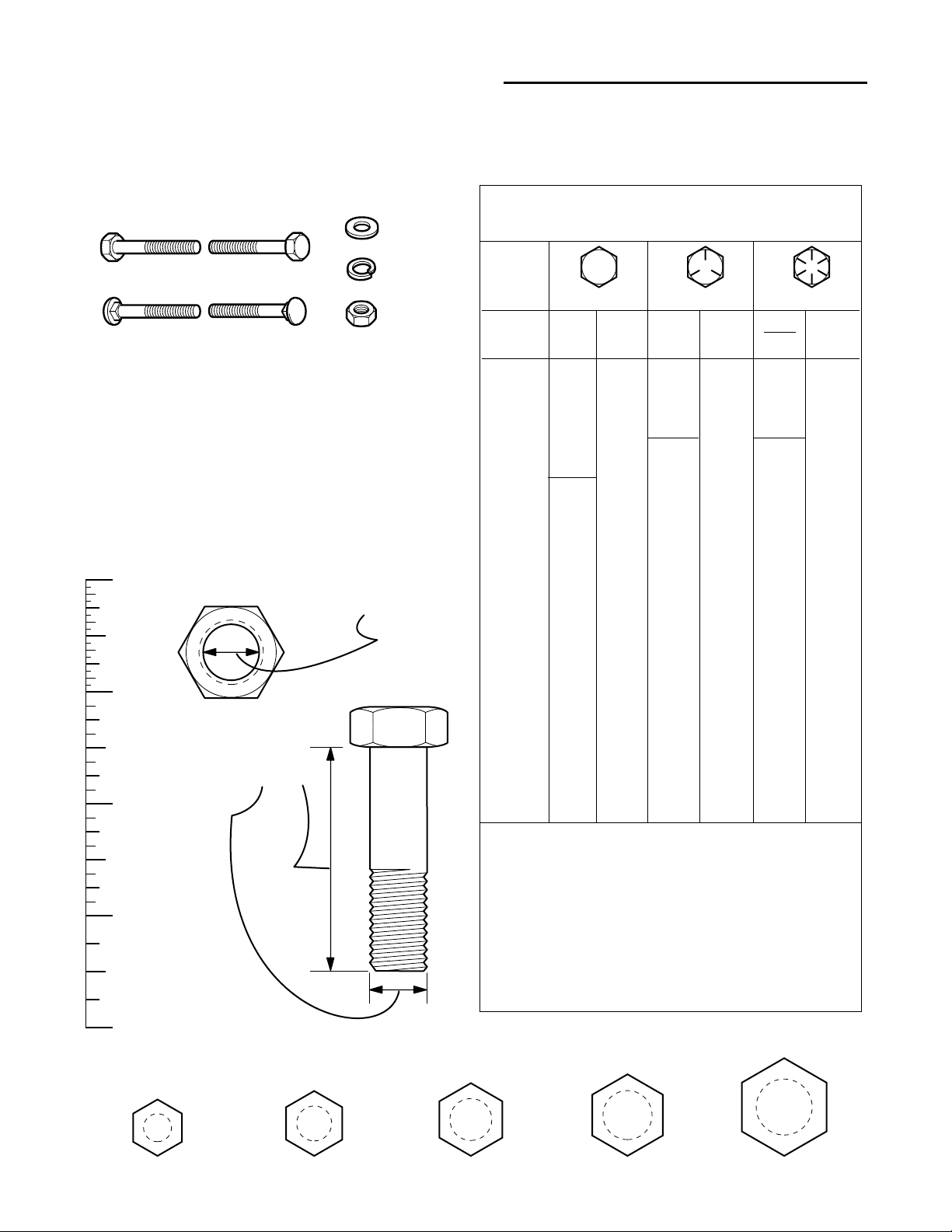
Hardware Identification & Torque Specifications
Common Hardware Types
Hex Head Capscrew
Carriage Bolt
Standard Hardware Sizing
When a washer or nut is identified as 1/2”, this is the
Nominal size
second number is present it represent the
When bolt or capscrew is identified as 1/2 - 16 x 2”, this
means the
second number represents the
example, and the final number is the
bolt or screw (in this example 2 inches long).
, meaning the
Nominal size
inside diameter
, or
body diameter
threads per inch
body length
Washer
Lockwasher
Hex Nut
is 1/2 inch; if a
threads per inch
is 1/2 inch; the
(16 in this
of the
The guides and ruler furnished below are designed to
help you select the appropriate hardware and tools.
0
1/4 3/4
1/2
Nut, 1/2”
Inside
Diameter
1
1/4 3/4
1/2
Screw, 1/2 x 2
2
1/4 3/4
1/2
3
1/4 3/4
1/2
4
Body
Diameter
Body
Length
Torque Specification Chart
FOR STANDARD MACHINE HARDWARE (Tolerance ± 20%)
Hardware
Grade
Size Of
Hardware ft/lbs Nm. ft/lbs Nm. ft/lbs Nm.
8-32
8-36
10-24
10-32
1/4-20
1/4-28
5/16-18 11 15.0 17 23.1 25 34.0
5/16-24 12 16.3 19 25.8 27 34.0
3/8-16 20 27.2 30 40.8 45 61.2
3/8-24 23 31.3 35 47.6 50 68.0
7/16-14 30 40.8 50 68.0 70 95.2
7/16-20 35 47.6 55 74.8 80 108.8
1/2-13 50 68.0 75 102.0 110 149.6
1/2-20 55 74.8 90 122.4 120 163.2
9/16-12 65 88.4 110 149.6 150 204.0
9/16-18 75 102.0 120 163.2 170 231.2
5/8-11 90 122.4 150 204.0 220 299.2
5/8-18 100 136 180 244.8 240 326.4
3/4-10 160 217.6 260 353.6 386 525.0
3/4-16 180 244.8 300 408.0 420 571.2
7/8-9 140 190.4 400 544.0 600 816.0
7/8-14 155 210.8 440 598.4 660 897.6
1-8 220 299.2 580 788.8 900 1,244.0
1-12 240 326.4 640 870.4 1,000 1,360.0
1. These torque values are to be used for all hardware
excluding: locknuts, self-tapping screws, thread forming
screws, sheet metal screws and socket head setscrews.
2. Recommended seating torque values for locknuts:
a. for prevailing torque locknuts - use 65% of grade 5
torques.
b. for flange whizlock nuts and screws - use 135% of
grade 5 torques.
3. Unless otherwise noted on assembly drawings, all torque
values must meet this specification.
No
Marks
SAE Grade 2 SAE Grade 5 SAE Grade 8
in/lbs in/lbs
19
20
27
31
66
76
2.1
2.3
3.1
3.5
7.6 8 10.9 12 16.3
8.6 10 13.6 14 19.0
30
31
43
49
NOTES
3.4
3.5
4.9
5.5
in/lbs
41
43
60
68
4.6
4.9
6.8
7.7
Wrench & Fastener Size Guide
1/4
5/16
3/8
7/16
DIA.
1/2
DIA.

2 - 1
2 Troubleshooting
Table of Contents
SECTION CONTENTS
Troubleshooting
Troubleshooting the Rider............................................................ 2-2
Troubleshooting the Mower.......................................................... 2-3
SECTION 2. TROUBLESHOOTING

2 Troubleshooting
Rider Troubleshooting
2- 2
TROUBLESHOOTING
The troubleshooting guide below lists some common
problems, their causes, and remedies.
See the repair information in the following sections for
instructions on how to perform most of these minor
repairs yourself. If you prefer, all of these procedures
can be performed for you by your local authorized dealer.
WARNING
Never attempt to perform repairs while the engine
is running.
Always turn the engine off and remove the key.
FAILURE TO COMPLY WITH THIS, AND OTHER,
SAFETY REQUIREMENTS CAN RESULT IN SERIOUS PERSONAL INJURY.
TROUBLESHOOTING THE RIDER
PROBLEM CAUSES REMEDIES
Engine will not turnover or start. 1. Ground speed control lever Shift into neutral.
not in neutral-start position.
2. PTO (electric clutch) switch Place in OFF position.
in ON position.
3. Out of fuel. If engine is hot, allow it to cool, then refill
the fuel tank.
4. Engine flooded. Move throttle control out of CHOKE position
5. Circuit breaker tripped. Wait one minute for automatic reset.
Replace if defective.
6. Battery terminals require Clean Battery.
cleaning.
7. Battery discharged or dead. Recharge or replace.
8. Wiring loose or broken. Visually check wiring & replace broken or
frayed wires. Tighten loose connections.
9. Solenoid or starter motor faulty. Repair or replace. See Electrical
Troubleshooting Section.
10. Safety interlock switch or Replace as needed. See Electrical
module faulty. Troubleshooting Section.
11. Spark plug(s) faulty, fouled Clean and gap or replace.
or incorrectly gapped. See engine manual.
12. Water in fuel. Drain fuel & refill with fresh fuel.
13. Gas is old or stale. Drain fuel & replace with fresh fuel.
14. Foot pedal not fully depressed. Depress pedal.
Engine starts hard or runs poorly. 1. Fuel mixture too rich. Clean air filter. Check throttle adjustment
2. Carburetor adjusted incorrectly. See engine manual.
3. Spark plug(s) faulty, fouled, or Clean and gap or replace.
incorrectly gapped. See engine manual.
Engine knocks. 1. Low oil level. Check/add oil as required.
2. Using wrong grade oil. See engine manual.
Excessive oil consumption. 1. Engine running too hot. Clean engine fins, blower screen and
air cleaner.
2. Using wrong weight oil. See engine manual.
3. Too much oil in crankcase. Drain excessive oil.
Engine exhaust is black. 1. Dirty air filter. Replace air filter. See engine manual.
2. Throttle is in choke position. Move throttle out of CHOKE position.
Engine runs, but rider will 1. Ground speed control lever Shift in forward or reverse.
not drive. in neutral.
2. Transmission release lever Move into “drive” position.
in “push” position.
(Hydro models only)
3. Drive belt is broken. See Drive Belt Replacement.
4. Drive belt slips. See problem and cause on next page.
5. Brake is not fully released. See Brake Adjustment.

2 - 3
2 Troubleshooting
Mower Troubleshooting
Rider Troubleshooting Cont.
PROBLEM CAUSES REMEDIES
Rider drive belt slips. 1. Clutch is out of adjustment. See Adjustments Section.
2. Pulleys or belt greasy or oily. Clean as required.
3. Belt stretched or worn. Replace with correct belt.
4. Idler pulley pivot bracket Remove idler pulley, clean and lubricate.
“frozen” in declutched position.
Brake will not hold. 1. Brake is incorrectly adjusted. See Brake Adjustment.
2. Internal brake disc on See Brake Adjustment and
transaxle worn. Transmission Repair Sections.
Rider steers hard or 1. Steering linkage is loose. Check and tighten any loose connections.
handles poorly. See Steering Gear Adjustment.
2. Improper tire inflation. Check and correct.
3. Wheel bearings dry. Grease wheels and lubricate steering linkage
or steering linkage dry See Lubricating the Rider.
Drive belt does not stop when 1. Belt stops or belt tension See Adjustments Section.
clutch/brake pedal depressed. out of adjustment.
TROUBLESHOOTING THE MOWER
PROBLEM CAUSES REMEDIES
Mower will not raise. 1. Lift not properly attached Attach or repair.
or damaged.
2. Lift Cable Broken Replace cable.
Mower cut is uneven. 1. Mower not leveled properly. See Mower Adjustment.
2. Rider tires not inflated See Maintenance Section.
equally or properly.
Mower cut is rough looking. 1. Engine speed too slow. Set to full speed.
2. Ground speed too fast. Slow down.
3. Blades are dull. Sharpen or replace blades.
See Mower Blade Service.
4. Mower drive belt slipping Clean or replace belt as necessary.
because it is oily or worn.
5. Blades not properly fastened See Mower Blade Service.
to arbors.
Engine stalls easily with 1. Engine speed too slow. Set to full throttle.
mower engaged. 2. Ground speed too fast. Slow down.
3. Carburetor improperly adjusted. See Engine Manual.
4. Cutting height set too low. Cut tall grass at maximum cutting
height during first pass.
5. Discharge chute jamming Cut grass with discharge pointing toward
with cut grass. previously cut area.
Excessive mower vibration. 1. Blade mounting screws Tighten to 50-70 ft.lbs. (74 N.m.).
are loose.
2. Mower blades, arbors, Check and replace as necessary.
or pulleys are bent.
3. Mower blades are out Remove, sharpen, and balance blades.
of balance. See Mower Blade Service.
4. Belt installed incorrectly. Reinstall Correctly.
Excessive belt wear or breakage. 1. Belt tension too tight. Adjust belt tension.
2. Bent or rough pulleys. Repair or replace.
3. Using incorrect belt. Replace with correct belt.
Mower drive belt slips 1. Idler pulley spring broken or not Repair or replace as needed.
or fails to drive. properly attached.
2. Belt stops out of adjustment. Check belt stops.
3. Mower drive belt broken. Replace drive belt.

2 Troubleshooting
Notes
2- 4

3 - 1
3 Maintenance
Table of Contents
SECTION CONTENTS
A. Storage
Temporary .............................................................................. 3-2
Long Term .............................................................................. 3-2
Starting After Long Term Storage .......................................... 3-3
B. Preventive Maintenance Chart .................................. 3-3
C. Maintenance & Adjustments
Tire Pressure .......................................................................... 3-3
Engine Oil Level ..................................................................... 3-5
Engine Oil Filter ...................................................................... 3-5
Engine Air Filter ...................................................................... 3-5
Fuel Filter ............................................................................... 3-5
Spark Plug .............................................................................. 3-6
Battery Maintenance .............................................................. 3-6
Mower Blade Service ............................................................. 3-7
Lubricating the Rider .............................................................. 3-8
Lubricating the Mower ............................................................ 3-9
SECTION 3. MAINTENANCE

3- 2
3 Maintenance
Storage
WARNING
Never store a rider, with gasoline in engine or fuel tank, in a heated shelter or in an enclosed, poorly
ventilated enclosure. Gasoline fumes may reach an open flame, spark or pilot light (such as a furnace,
water heater, clothes dryer, etc.) and cause an explosion.
Handle gasoline carefully. It is highly flammable and careless use could result in serious fire damage to
your person or property.
Drain fuel into an approved container outdoors away from open flame or sparks.
A. STORAGE
Temporary Storage
(30 Days Or Less)
Remember, the fuel tank will still contain some gasoline,
so never store the rider indoors where fuel vapor could
travel to any ignition source. Fuel vapor is also toxic if
inhaled, so never store the rider in any structure used for
human or animal habitation.
Here is a checklist of things to do when storing your rider
temporarily or in between uses:
• Do not store the rider in an area where children
may come into contact with it. If there is any
chance of unauthorized use, remove the ignition
key and keep it in a safe place.
• If the rider cannot be stored on a reasonably level
surface, block the wheels.
• Clean all grass and dirt from the mower.
Long Term Storage
(Longer Than 30 Days)
Before you store your rider for the off-season, read the
Maintenance and Storage instructions in the Safety
Rules section, then perform the following steps:
1. Drain crankcase oil and refill with a grade of oil that
will be required when rider is used again.
2. Prepare the mower deck for storage as follows:
a. Remove mower deck from the rider. (See
Operators Manual)
b. Clean underside of mower deck.
c. Coat all bare metal surface with paint or light coat
of oil to prevent rusting.
3. Clean external surfaces and engine.
4. Prepare engine for storage. See engine owner’s
manual.
5. Clean any dirt or grass from cylinder head cooling
fins, engine housing and air cleaner element.
6. Cover air cleaner and exhaust outlet tightly with plastic or other waterproof material to keep out moisture,
dirt and insects.
7. Completely grease and oil rider as outlined in the
Lubrication section.
8. Clean up rider and apply paint or rust preventative to
any areas where paint is chipped or damaged.
9. Be sure the battery is filled to the proper level with
water and is fully charged. Battery life will be
increased if it is removed, put in a cool, dry place and
fully charged about once a month. Do not allow the
battery to freeze. If the battery is left in the rider, disconnect the negative cable.
10.Drain the fuel system completely or add a gasoline
stabilizer to the fuel system. If you have chosen to
use a fuel stabilizer and have not drained the fuel
system, follow all safety instructions and storage precautions in this manual to prevent the possibility of
fire from the ignition of gasoline fumes. Remember,
gasoline fumes can travel to distant sources of ignition and ignite, causing risk of explosion and fire.
NOTE: Gasoline, if permitted to stand unused for extended periods (30 days or more), may develop gummy
deposits which can adversely affect the engine carburetor and cause engine malfunction. To avoid this condition, add a gasoline stabilizer to the fuel tank or drain all
fuel from the system before placing unit in storage.
11.Transport the rider to a suitable, dry, indoor location.
If the rider is to be stored 6 months or longer, block
the rider up off the wheels to relieve weight and also
to keep the tires off a damp floor. Protect tires from
prolonged exposure to direct sunlight.

3 - 3
3 Maintenance
Storage / Chart
Starting After Long Term Storage
Before starting the rider after it has been stored for a long period of time, perform the following steps:
1. Remove the blocks from under the rider.
2. Install the battery if it was removed.
3. Unplug the exhaust outlet and air cleaner.
4. Fill the fuel tank with fresh gasoline. See engine manual for recommendations.
5. Check crankcase oil level and add proper oil if necessary.
6. Inflate tires to proper pressure.
7. Check all fluid levels.
8. Start the engine and let it run slowly until warm. DO NOT run at high speed immediately after starting. Be sure to
run engine only outdoors or in well ventilated areas.
B. PREVENTIVE MAINTENANCE CHART
The following schedule should be followed for normal care of your rider and mower. You will need to keep a record of
your operating time. Determining operating time is easily accomplished by multiplying the time it takes to do one job
by the number of times you’ve done the job, or you can install the optional hour meter.
Before Before Every Every 25 Every 100 Spring
Safety Items First Use Each Use 5 Hours Hours Hours & Fall
Check safety interlock system. ● ●
Check rider brakes. ● ●
Check mower blade stopping time. ●●
Normal Care Items
Check rider & mower for loose hardware. ●● ●
Check engine oil level.* ●● ● ●
Check engine & air filter.* ***●
Change engine oil and filter. (Select Models)* ** ***Every 50 hrs. ***●
Lubricate rider & mower. ***●
Check fluid levels & tire pressure ●● **●
Change transmission fluid.
(Hydro only)****
Only if transaxle is serviced.
Check fuel filter. ●
Clean battery & cables ●
Clean/sharpen blades. ●
Inspect spark plug.* ●
* See the engine manufacturer's owner's manual.
** Change original engine oil after first 5 hours of operation.
*** More often in hot (over 85° F: 30° C) weather or dusty operating conditions.
Tire Pressure
Front 12-16 psi (82-103 kPa)
Rear 6-8 psi (41-55 kPa)
TIRE PRESSURE
Front and rear tires should be checked periodically to
ensure that proper tire pressure is maintained. Note that
these pressures differ slightly from the “Max Inflation”
stamped on the side-wall of the tire. Keeping the tires
properly inflated to these settings helps provide proper
traction, extend tire life, and improved cut quality.
3- 4
3 Maintenance
Engine
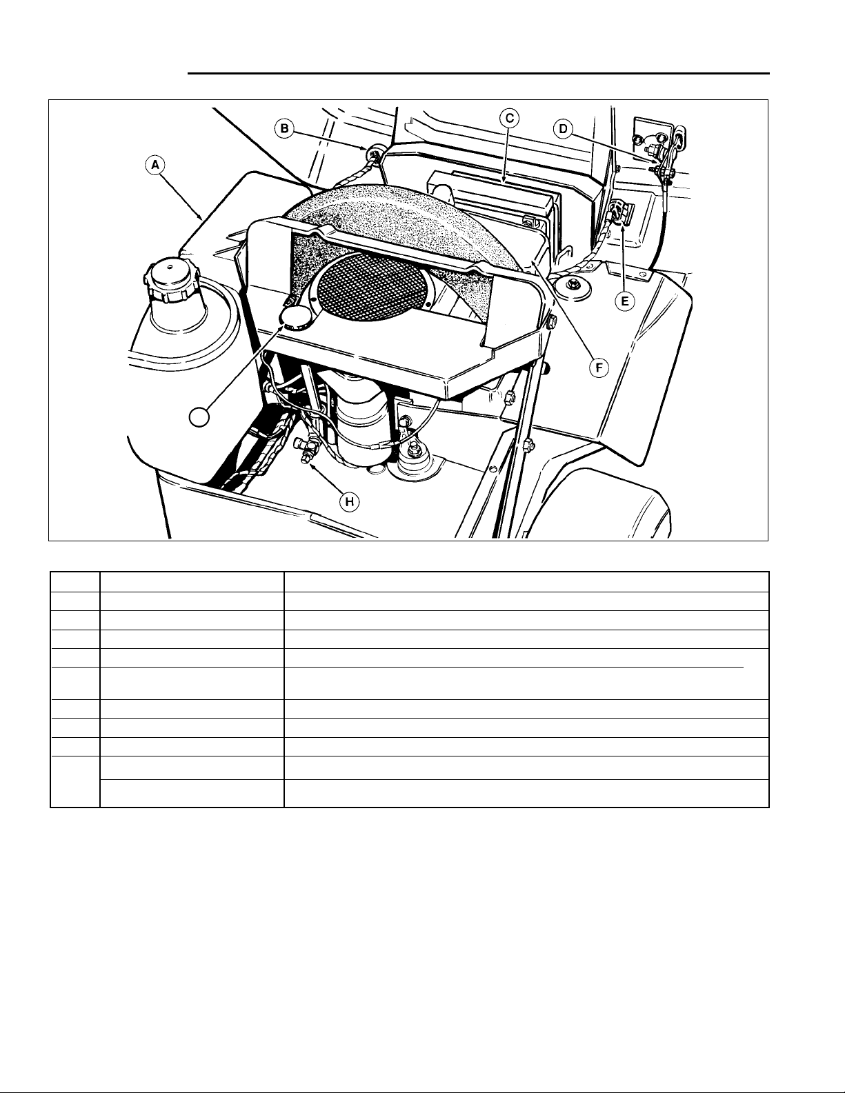
REF NAME FUNCTION
A Fuel Tank 2 gal. (7.6L) see-through tank for fuel level reading.
B Ignition Switch Starts and stops the engine.
C Battery 12 volt, 340 amp battery recharged by engine alternator
D Throttle/Choke Cable Controls engine speed and choke position. See engine manual for adjustment.
E PTO Switch (Electric Clutch) Controls electric clutch for attachments. Pull out to engage clutch; push in to disen-
gage.
F Air Filter See engine manual for maintenance instructions.
G Oil Fill/Dipstick Turn and remove to check or add oil. See engine manual for dipstick instruction.
H Oil Drain Attach clear plastic tube to drain outlet and open valve to drain oil.
Not Fuel Filter In-line filter for straining particles in fuel lines and fuel tank.
Shown
Oil Filter Oil Filter strains particulate materials out of engine oil.
Figure 1. Engine Compartment - Typical
*2387
G

3 - 5
3 Maintenance
Engine
C. ENGINE MAINTENANCE
ENGINE OIL LEVEL
Engine oil level must be checked at regular intervals to
ensure that engine oil is maintained at a level that will
provide for adequate lubrication of internal components.
Operating the engine with insufficient oil in the oil sump
will cause engine components to wear prematurely, and
prolonged use with low oil levels may cause engine overheating, permanent damage, and voiding of the engine
manufacturer’s warranty.
In addition to following the engine manufacturer’s instructions for checking oil level, the recommendations for oil
type and viscosity must also be followed. These recommendations vary based on the season during which the
unit is being operated, and may require that the oil be
changed to suit different operating conditions.
The location of the oil level indicator and oil fill tube are
indicated in the engine manufacturer’s manual shipped
with each unit. In general, the oil fill tube is marked with
an oil can symbol or the word “OIL”, and is located next
to the engine to permit easy access (See Figure 1).
The engine oil fill tube is usually also the location of the
engine oil level dipstick, allowing oil level checks and filling to be performed using the same tube.
ENGINE OIL FILTER (WHERE
APPLICABLE)
The engine oil filter should be changed in accordance
with the engine manufacturer’s recommendations, which
is generally every 100 hours of operation, or more frequently when operating conditions are hot (over 85°), or
dusty.
The oil filter removes abrasive particles and other contaminants from the oil, keeping it clean for maximum lubrication efficiency, and should only be replaced with the
type of filter recommended by the engine manufacturer.
The oil filter is located at the base of the engine, and is
removed by unscrewing the filter from the filter base
using an oil filter wrench.
ENGINE AIR FILTER
The engine air filter filters out dust and dirt from the air
intake of the engine, and must be cleaned or replaced
every 25 hours of operation, or more frequently when
operating conditions are dusty.
Follow the engine manufacturer’s recommendations for
removal, cleaning, and replacement. See Figure 1for air
filter locations.
FUEL FILTER
The fuel filter is located in the engine compartment and
is installed in the rubber fuel line between the fuel tank
and the fuel pump. The fuel filter should be checked
every 100 hours of operation, or sooner and replaced if it
appears to be dirty or clogged.
A dirty or clogged filter may cause erratic engine operation, hard starting, or loss of power.
Before removing the hoses from the fuel filter, place a
small container under the filter to catch the gasoline in
the hoses and filter that will drain out as the filter is
removed.
1. Squeeze the tabs on the hose clamps together using
a pliers, and slide the clamps away from the fuel filter.
2. Note the fuel flow direction indicated on the filter, and
remove the filter by pulling the hoses away from the
filter with a twisting motion. Be prepared for fuel in
the hoses and fuel filter to drain out as the hoses are
disconnected, and catch the fuel in the container.
3. Observing the same fuel filter flow direction noted
during removal, install the new fuel filter in the fuel
line by sliding the hoses onto the filter.
4. Squeeze the tabs on the hose clamps together, and
slide the clamps into place over the fuel filter tubes to
secure the fuel lines to the fuel filter.
NOTE: The hose clamps must connect the fuel line
hoses to the fuel filter securely to prevent fuel leakage
and the possibility of engine compartment fire. Replace
the hose clamps if they do not provide a secure, leakproof attachment to the fuel filter.
NOTE: Replace old, brittle, hard, or cracked fuel line.
DANGER
Do not remove fuel filter when engine is hot, as
spilled gasoline may ignite. Follow all precautions for the safe handling of gasoline when
removing and installing the fuel filter. DO NOT
spread hose clamps more than necessary.
Replace clamps if they do not provide a secure,
leak-proof attachment to the fuel filter when reinstalled.
3- 6
3 Maintenance
Engine / Battery
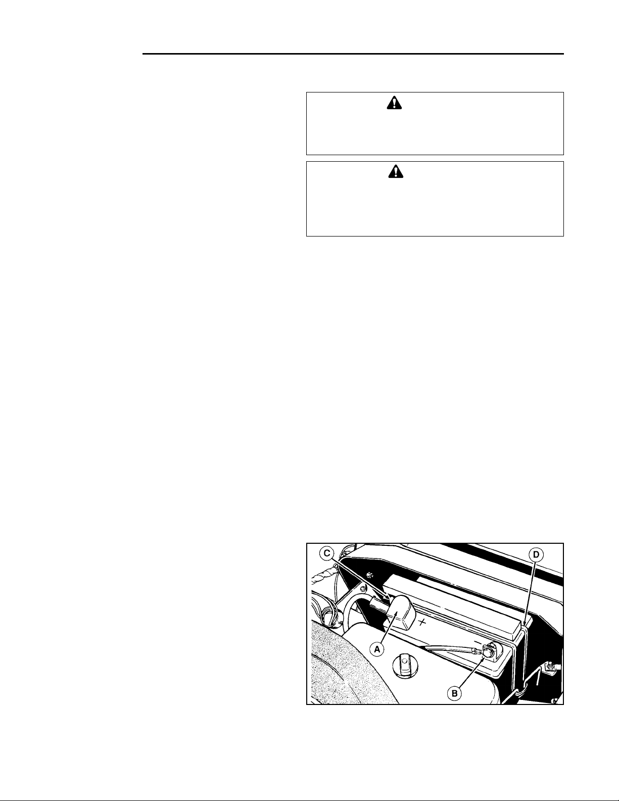
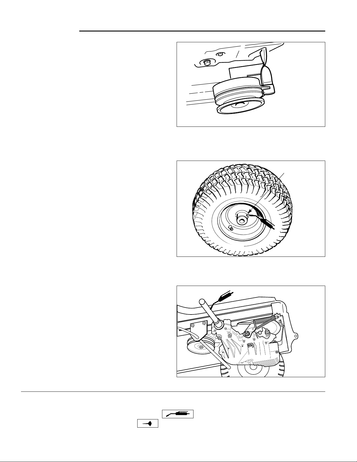
BATTERY MAINTENANCE
Checking the Battery Fluid
1. Raise the hood.
2. Remove battery filler cap. Fluid must be even with split
ring full mark. If not, add distilled water.
3. Reinstall filler cap.
Cleaning the Battery and Cables
1. Disconnect the cables from the battery, negative
cable first (B, Figure 2).
2. Remove the holddown strap (D), then remove the
battery.
3. Scrub the battery, cables and battery compartment
with baking soda and water.
4. Clean the battery terminals and cable clamps with a
wire brush and battery post terminal cleaner.
5. Reinstall battery and holddown strap.
6. Connect cables, positive cable first.
7. Coat battery cable clamps and battery terminals with
a protective anti-corrosive coating such as petroleum
jelly.
WARNING
Be careful when handling the battery. Avoid
spilling electrolyte. Keep flames and sparks
away from the battery.
WARNING
When removing or installing battery cables, disconnect the negative cable FIRST and reconnect
it LAST. If not done in this order, the positive terminal can be shorted to the frame by a tool.
SPARK PLUG
The spark plug(s) should be inspected at the regular
intervals specified in the engine manufacturer’s owner’s
manual and cleaned or replaced as required.
Dirty, worn, or fouled spark plugs may cause hard starting, rough engine operation, or loss of power, and may
contribute to premature starter failure from excessive
cranking of the engine.
The spark plug(s) can be found by looking for the thick
black spark plug cable(s) at the engine head, and removing the spark plug boot(s) that connect(s) the cable to the
spark plug.
The spark plug boot can be removed from the spark plug
by pulling the boot away from the spark plug with a slight
side-to-side motion.
To remove the spark plug(s) from the engine for inspection or replacement:
1. Turn the ignition off and remove the key. Allow
engine to cool.
2. Raise the hood.
3. Locate the spark plug cable and boot, and pull the
boot off the spark plug.
4. Using a spark plug socket and socket wrench or
equivalent spark plug removal tool, unscrew the
spark plug from the engine by turning the spark plug
counter-clockwise.
5. Inspect the spark plug in accordance with the engine
manufacturer’s instructions, and clean, re-gap, or
replace the spark plug as required.
6. When reinstalling the spark plug, start the plug into
the engine by first turning it clockwise by hand to prevent cross-threading and possible damage to the
spark plug port. Tighten as instructed in engine manufacturer’s manual.
Figure 2. Battery
A. Positive Battery Terminal C. Vent Tube
B. Negative Battery Terminal D. Holddown Strap
3 - 7
3 Maintenance
Mower Blade Service
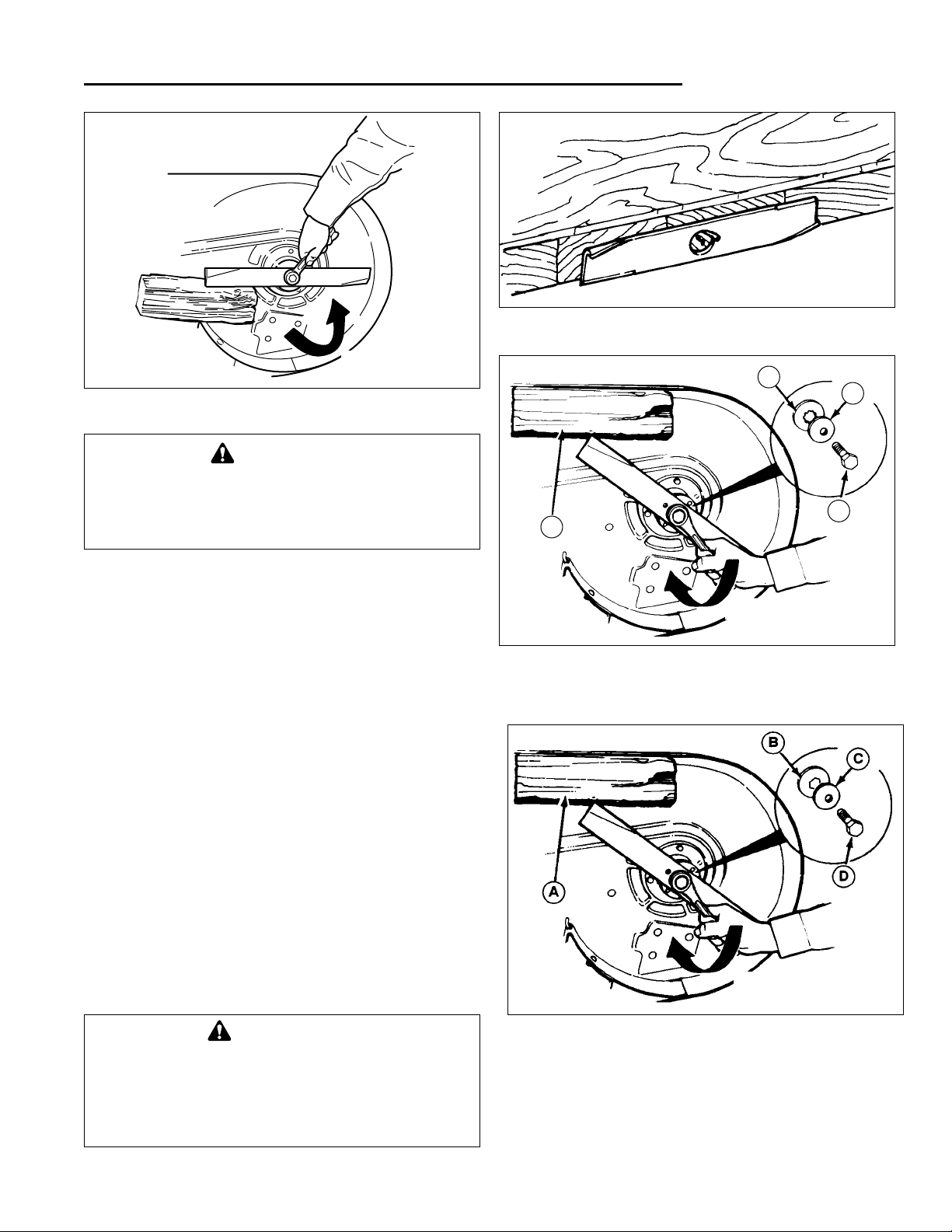
MOWER BLADE SERVICE
1. Remove mower from the rider. See Operators
Manual.
2. Blades should be sharp and free of nicks and dents.
If not, sharpen blades as described in following steps.
3. To remove blade for sharpening, use wooden block
to hold blade while removing the blade mounting capscrew (Figure 3).
4. Use a file to sharpen blade to fine edge. Remove all
nicks and dents in blade edge. If blade is severely
damaged, it should be replaced.
5. Balance the blade as shown in Figure 4. Center the
blades’ hole on a nail lubricated with a drop of oil. A
balanced blade will remain level.
6.Reinstall each blade with the tabs pointing up toward
deck as shown in Figures 5 & 6. Secure with a capscrew (D), cup washer (C) and spline or hex washer
(B). Use a wooden block to prevent blade rotation
and torque capscrews to 50-70 ft.lbs. (67-95 N.m.).
LOOSEN
Figure 3. Removing The Blade
Figure 4. Balancing The Blade
Figure 5. Installing The Blade (Early Models)
A. 4X4 Wooden Block C. Cup Washer
B. Spline Washer D. Capscrew
TIGHTEN
A
B
D
C
WARNING
Blade mounting capscrews must each be
installed with a cup washer and spline washer,
then securely tightened. Torque blade mounting
capscrew to 50-70 ft.lbs. (67-95 N.m.)
WARNING
For your personal safety, do not handle the
sharp mower blades with bare hands. Careless
or improper handling of blades may result in
serious injury.
Figure 6. Installing The Blade (Later Models)
A. 4X4 Wooden Block C. Cup Washer
B. Hex Washer D. Capscrew
TIGHTEN
3- 8
3 Maintenance
Lubrication
LUBRICATION
Lubricating the Rider
Lubricate the rider as shown in Figures 7 through
15. When a grease gun is shown, wipe the fitting clean,
apply two or three pumps of lithium base automotive
grease, and wipe off excess grease. When an oil can is
shown, wipe the area clean, apply a few drops of SAE 30
weight oil, then wipe up drips or spills.
In general, linkage connections and other parts that have
partial rotational or sliding movement (pedal pivot points,
steering links, etc.) should be lubricated periodically with
SAE 30 weight oil. Avoid applying excessive amounts of
oil since this may cause a build-up of dirt and grass clippings around the lubricated area, making subsequent
lubrication more difficult to accomplish.
Roller bearings, bushings, axles, rotating assemblies
with grease fittings, and mechanisms with exposed gear
teeth (steering gears) require periodic lubrication with
lithium grease.
When grease fittings are present, a manual or pneumatic
pressure-feed grease gun should be utilized to inject
enough grease through the fitting to fully permeate the
enclosed area containing the bearings or other moving
parts.
Plain bushings, bearings, axles without grease fittings,
and exposed gear teeth require the direct application of
grease to all wear surfaces. Use a small, clean applicator
brush or other means of applying and spreading the
grease evenly.
Special care should be taken with ball and roller bearings
to ensure that a liberal application of grease is applied to
the bearing rollers or balls, and both inner and outer
races or bearing and bearing cups.
Remove the rear wheels and grease the axle shafts to
prevent the wheels from seizing onto the shafts.
Lubricating the Mower
Lubricate the mower as shown in Figures 12 and 15. Be
sure to lubricate the grease fittings on the mower idler
pulley and arbors, which are located underneath the
mower deck.
Avoid getting grease or oil on belts and pulley when
applying lubricants, and always wipe away excess oil
and grease to prevent a rapid build-up of dirt and debris
from accumulating.
Figure 8. Front Wheel Bushing Lubrication - Grease
Fitting Location (Inside hub of wheel). Wheel shown
removed from axle for visual clarity.
Front Wheel
Grease
Fitting
Figure 7. PTO (Electric clutch) The Clutch Anchor
Tab is Covered by A Plastic Cap and Does Not
Require Lubrication. Early Models Not Equipped
with a Plastic Cover Should Be Oiled Yearly
NOTES:
1. Unless specified, use torque specifications shown on standard hardware torque specification chart.
2. Grease locations indicated by grease gun symbol:
3. Oil locations indicated by oil can symbol:
Figure 9. Lube Axle Shafts.
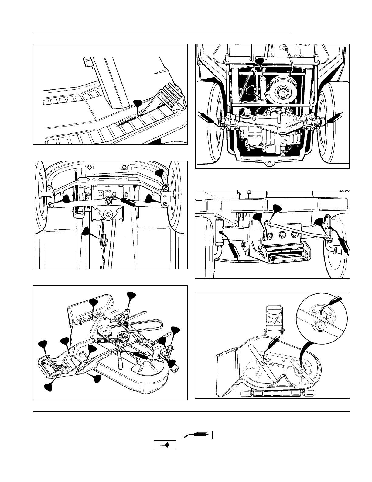
3 - 9
3 Maintenance
Lubrication
*2388B
Figure 10. Brake Pedal Pivot Point
Figure 14. Front Axle Lubrication Points
Figure 13. Rider Lubrication Points - Rear Half (Gear
Model Shown)
Figure 11. Rider Lubrication Points - Front Half
*2402
*2390
NOTES:
1. Unless specified, use torque specifications shown on standard hardware torque specification chart.
2. Grease locations indicated by grease gun symbol:
3. Oil locations indicated by oil can symbol:
*2397
Figure 12. Mower Deck Lubrication Points
Figure 15. Arbor Lubrication Points
Note: On 30” mower,
grease fitting is on
topside of deck.
 Loading...