

Page 1

How to use this file...(Operators Manuals)
————————————————————————————————————————————–––
Instructions for
Print Vendors (Paper Manuals)
Paper Size: * 11 x 17
* Body—50 lbs brilliant white offset or equivalent.
* Cover—on pre-printed two-tone “Swash” stock.
Press: * Body—1-color, 2-sided
* Cover imprint —1-color, 1-sided
Bindery:* Saddle Stitch, Face Trim
* Face Trim
COVERS: * This file contains several manuals, which differ only in their covers.
* Covers are all present at the beginning of this file.
* Back cover for a particular manual is the page IMMEDIATELY AFTER the front cover.
• Check the front cover for the individual part number (typically a 171xxxx number).
BODY: • The body of the manual is identical, regardless of the cover used.
* REMEMBER: ODD number pages are ALWAYS right hand pages, and EVEN number are ALWAYS
left hand pages.
General: * This instruction page is NOT part of the manual and must NOT be printed.
• Pages labeled with the text “THIS PAGE INTENTIONALLY BLANK” are placement pages ONLY,
and should NOT be printed.
————————————————————————————————————————————–––
If you have further questions on how to utilize this file, please contact
Simplicity Technical Publications Department at (262) 284-8647.
Page 2

THIS PAGE INTENTIONALLY BLANK
Page 3
Attachment
OPERATOR’S
MANUAL
Snowthrower & Hitch
36” Snowthrower
Mfg. No. Description
1691521 36” Snowthrower Attachment
42” Snowthrower
Mfg. No. Description
1691522 42” Snowthrower Attachment
Hitch
Mfg. No. Description
1692040 Hitch, Electric Lift (for Landlord / 1700 / 2700 Series)
1692041 Hitch, Manual Lift (for Broadmoor / 1600 / 2600 Series)
1692622 Hitch, Manual Lift (for Regent / 500 / 2500 Series)
1715020-05
Rev 6/1998
TP 100-2014-05-AT-SMA
Page 4

Simplicity Mfg. Inc.
500 N Spring Street / PO Box 997
Port Washington, WI 53074-0997 USA
© Copyright 1998, Simplicity Manufacturing, Inc.
All Rights Reserved. Printed in USA.
Page 5
1
General
Recommended Accessories
Tire chains and a weight box are recommended when installing
this attachment to your unit. These accessories will improve traction, thereby making the snowthrower more efficient. For additional traction, one wheel weight per wheel is recommended.
Weight added to the tractor should not exceed 35 lbs. per wheel
and 100 lbs. additional weight with the weight box.
For operation on slopes greater than 15% (8.5°), weight box, tire
chains and wheel weights are recommended. Never operate on
slopes greater than 30% (16.7°). See Operation on Slopes, page 3.
NOTE: Large Lift Lever Kit (part no. 1691832) is required for
Regent/2500/500 Series & Broadmoor/LT/2600/1600 Series tractors, if not already factory installed. The Landlord/GT/2700/1700
Series tractors come factory equipped with either the large lift
lever or an electric lift.
Safety Decals
Part No. 1716532
Auger Danger Decal
Part No. 1716533
Discharge Chute Danger Decal
Part No. 1716531
Main Operation Warning Decal
Part No. 1716536
Spring Tension Caution Decal
OPERATION AND USE
Recommended Accessories .......................1
Safety Decals ................................................1
Safety Rules..................................................2
Operation ......................................................3
Maintenance..................................................5
Belt Replacement .........................................7
Adjustments..................................................7
Belt Tension Adjustment............................7
Skid Shoe Adjustment ...............................7
Lift Rod Adjustment ...................................8
Troubleshooting ...........................................9
ASSEMBLY AND INSTALLATION
Regent / 500 / 2500 Series See Page 10-15
Snowthrower Assembly ...........................10
Hitch Installation ......................................12
Snowthrower Installation .........................14
Broadmoor / 1600 / 2600 Series See Pages 16-20
Snowthrower Assembly ...........................16
Hitch Installation ......................................18
Snowthrower Installation .........................20
Landlord / 1700 / 2700 Series See Pages 22-26
Snowthrower Assembly ...........................22
Hitch Installation ......................................25
Snowthrower Installation .........................26
Standard Torque Specifications ...............29
Standard Fastener Identification ..............30
Lift Lever Kit Installation Instructions......31
NOTE: In these instructions, “left” and “right”
are referred to as seen from the operating
position.
Part No. 1716887
Tire Fluid Caution Decal (Regent Series Only)
© Copyright 1997 Simplicity Manufacturing, Inc.
All Rights Reserved. Printed in USA.
TP 100-2014-05-AT-SMA
DANGER
AVOID INJURY
FROM ROTATING
AUGER!
Keep hands, feet,
1716532
and clothing away.
DANGER
AVOID INJURY
FROM ROTATING
BLOWER!
Shut off engine
before unclogging
1716533
discharge chute.
CAUTION
SPRING IS UNDER TENSION. RAISE
SNOWTHROWER BEFORE PULLING LEVER
BACK TO DISCONNECT SPRING.
WARNING
TO AVOID SERIOUS INJURY OR DEATH
• Refer to Operator's Manual for Safety and
Operating Instructions.
• Keep all guards and shields in place.
• Stop engine, remove key, and be sure all
moving parts have come to a complete
stop before servicing or unplugging.
CAUTION
• Do not use hands to unplug chute or auger.
• Always direct discharge so as to avoid injury
to persons —or damage to property.
• Never allow anyone in front of the machine
while it is operating.
WHEN OPERATING TRACTOR
WITHOUT SNOWTHROWER ATTACHED,
FLUID IN FRONT TIRES IS REQUIRED.
1716536
1716531
1716887
Page 6

General
• Read this manual and the tractor Operator’s Manual
carefully. Be thoroughly familiar with the controls and
the proper use of the equipment.
• Never pull the spring-assist tension lever back unless
snowthrower is in fully raised position. The spring is
under tension when snowthrower is in lowered position.
• Never allow children to operate the machine. Do not
allow adults to operate it without proper instruction.
• Do not carry passengers.
• Use only attachments or accessories designed for
your machine. See your dealer for a complete list of
recommended attachments or accessories.
• Keep the area of operation clear of all persons, particularly small children, and pets.
• Never direct discharge chute towards bystanders.
• Make sure all hardware is secure and that
snowthrower is in good operating condition.
• Check to be sure all safety devices and shields are in
place.
• Check that all adjustments are correct before using
this unit.
2
Safety Rules
Read these safety rules, and the safety rules in your tractor Operator’s Manual, and follow them
closely. Failure to obey these rules could result in loss of control of vehicle, severe personal injury
to yourself, or damage to property or equipment. The triangle in the text signifies important cau-
tions or warnings which must be followed.
WARNING
If the auger stalls or the chute plugs, disengage the
electric clutch (PTO), stop the engine and remove the
key. set the parking brake. wait for moving parts to
stop. Remove the foreign object or clear the chute with
a piece of wood before restarting the engine. Never
place hands into blower housing to clear jammed
object. Auger may rotate when object is removed.
WARNING
For operation on slopes greater than 15% (8.5°),
weight box, tire chains and wheel weights are recommended. Never operate on slopes greater than 30%
(16.7°).
Preparation
• Never attempt to make any adjustments while engine
is running.
• Thoroughly inspect the area where the snowthrower
is to be operated and remove all foreign objects.
• Adjust the skid shoe height to clear gravel or crushed
stone surface. See the Maintenance and Adjustments
section for procedure.
Operation
• Always clear snow up and down the face of slopes,
never across the face. Exercise extreme caution
when changing direction on slopes. Do not attempt to
clear steep slopes.
• Exercise extreme caution when operating on, or
crossing, gravel drives, walks or roads. Stay alert for
hidden hazards or traffic.
• After striking an object or if unit starts to vibrate
abnormally, stop the engine, disengage the PTO, and
remove the key. Check for the cause and any damage before restarting. Before any inspection, make
sure all moving parts have stopped.
• Take all possible precautions before leaving operator’s position. Disengage the PTO, lower the attachment, set the parking brake, stop the engine and
remove the key.
• Never operate the snowthrower near glass enclosures, automobiles, window wells, dropoffs, etc.,
without proper adjustment of discharge angle.
• Do not overload machine capacity by attempting to
clear snow at too fast a rate.
• Never operate unit at high transport speeds on slippery surfaces. Use care when travelling in reverse.
• Disengage power to snowthrower when transporting
or not in use.
• Never operate the snowthrower without good visibility
or light. Always be sure your feet are properly placed
on the footrests and keep a firm hold on the steering
wheel.
Page 7
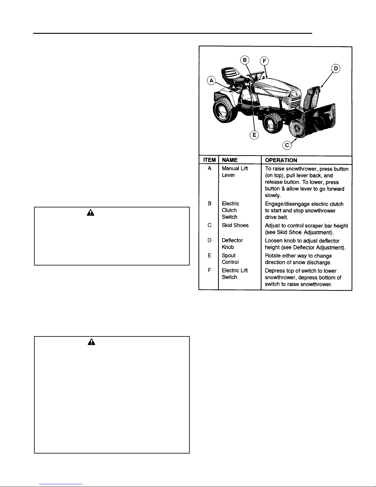
Controls
Read and understand the instructions in your tractor
Operator’s Manual.
See Figure 1 for location, name, and description of the
snowthrower controls.
Checks Before Starting
1. Refer to the Maintenance & Adjustments section of
this manual and perform any needed service. Also,
refer to the tractor Operator’s Manual and perform
any required service.
2. Remove any objects from the work area which might
be caught in, or thrown by, the auger.
3. Before starting the engine, clear the auger of any ice
particles which may cause damage to auger.
4. Adjust the deflector and skid shoes to desired height.
See Skid Shoe Adjustment and Deflector Adjustment.
5. Make sure all hardware is present and secure.
Figure 1. Snowthrower Controls
WARNING
• Never operate on slopes greater than 30%
(16.7o), which is a rise of three feet (.9m) vertically in 10 feet (3.1m) horizontally.
• When operating on slopes greater than 15%
(8.5o), one wheel weight on each rear wheel and
tire chains are recommended.
• Select slow ground speed before driving onto a
slope. Avoid using brakes to control speed.
• Drive up and down the face of the slopes, never
across the slope face.
• Use caution when changing directions and DO
NOT START OR STOP ON A SLOPE.
WARNING
Perform the Safety System Interlock test found in
your tractor Operator’s Manual. If tractor does not
pass the test, do not operate the tractor. See your
authorized dealer. Under no circumstances should
you attempt to defeat the safety system.
Operating On Slopes Transporting
1. Disengage the electric clutch and then raise the
snowthrower.
2. Adjust ground speed according to surface conditions.
3. Select a low ground speed when transporting on a
slippery surface.
Engine & Ground Speed Selection
Always run the engine at full throttle.
Normally, a low ground speed is best for throwing snow.
The deeper or heavier the snow, the slower the recommended ground speed.
3
Operation
Page 8

4
Operation
Starting & Stopping
1. Start the tractor engine. Set engine throttle at 1/2
speed.
2. Lower the snowthrower.
3. Engage the electric clutch switch. Snowthrower auger
should rotate. Disengage the electric clutch switch.
snowthrower auger should stop.
4. Adjust the engine speed to full speed. Select the
proper ground speed.
5. To stop the tractor, depress the clutch/brake pedal.
To stop the snowthrower, disengage the electric
clutch. Before leaving the seat, stop the engine, disengage the electric clutch, set the parking brake,
remove the key, and wait for all moving parts to stop.
Snow Removal Suggestions
• Determine the best snow removal pattern before
beginning.
• Wind direction is an important factor to consider.
Rotate the spout to discharge snow downwind.
• Plan the pattern so that you avoid throwing snow on
cleared areas and on yourself as your are operating.
• When land contour permits, it is best to travel in the
longest direction to minimize turning.
• In very deep or heavy snow, it may be necessary to
make the first pass with snowthrower partially raised,
backing up every few feet to clear the snow left on
the surface. Also, it may be necessary to slice off less
than the full width of the auger or reduce ground
speed.
• If snow stops flowing freely from the spout, back
away until the snowthrower clears itself.
CAUTION
Always raise the snowthrower before turning or
backing up, to prevent damage to the unit.
WARNING
If auger does not start and stop when
engaging/disengaging electric clutch, see your
authorized dealer. Under no circumstances should
you attempt to defeat the safety system.
WARNING
If the auger stalls or the chute plugs, DISENGAGE
THE ELECTRIC CLUTCH, STOP THE ENGINE AND
REMOVE THE KEY. SET THE PARKING BRAKE.
WAIT FOR MOVING PARTS TO STOP. Remove the
foreign object or clear the spout with a piece of
wood before restarting the engine. Never place
hands into auger housing or spout to clear
jammed object. Auger may rotate when object is
removed.
Snowthrower & Hitch Removal
Remove the snowthrower and hitch in the reverse order
of installation. Note the following:
• Always remove the 4-link chain from the spring assist
bracket to prevent interference with front steering
components.
• Use caution when removing the spring from the
spring-assist lever and chain. Snowthrower must be
in fully raised position to relieve spring tension.
• Whenever removed, install clevis pins, hitch pins,
clips and hardware onto snowthrower and hitch for
storage.
Daily Storage
1. Run the snowthrower a few minutes after blowing
snow to prevent freeze-up of auger and impeller.
2. Allow tractor engine to cool before storing in any
enclosure.
Off-Season Storage
1. Remove snowthrower from the tractor. Hitch can
remain installed if other attachments are to be used.
2. Use water pressure or a brush to thoroughly clean
the housing.
3. Paint, or lightly coat with oil, any area where paint
has been worn or chipped away.
4. Lubricate the snowthrower.
5. Store the snowthrower and hitch in a dry place.
WARNING
To prevent an explosion or fire, never store the
tractor with fuel in the tank inside a building where
an ignition source is present.
Page 9
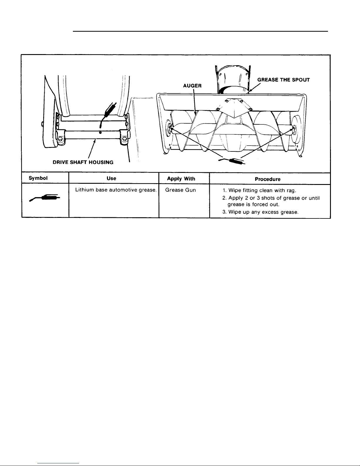
5
Maintenance
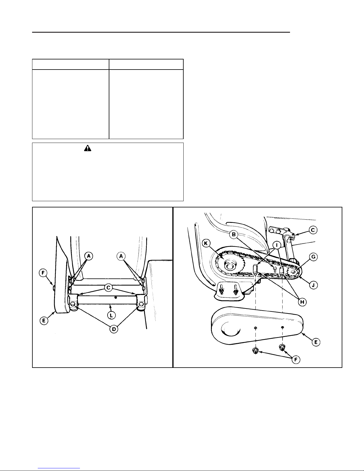
Figure 2. Drive Chain
A. Screws D. Screw G. Drive Shaft Sprocket J. Chain
B. Flange Nut E. Chain Guard H. Spacers K. Auger Sprocket
C. Clamps F. Nuts I. Nuts L. Drive Shaft Housing
Schedule For Normal Care
Care Required Schedule
Clean snow and ice from After each use.
snowthrower.
Lubricate snowthrower. Every 10 hours or at
least once a year.
Adjust belt tension. Every 25 hours or at
least once a year.
Inspect, adjust and Once a year or more
lubricate drive chain. often under frequent
use.
Inspect, Adjust & Lubricate Drive Chain
See Figure 2.
1. Remove the two nuts (F) and chain guard (E).
2. Check the chain for wear or damage. Replace chain
if worn or damaged.
3. There should be no slack in the chain, and the
sprockets (G and K) should be aligned. The drive
shaft housing (L) should be parallel with the auger
housing. If adjustment is required proceed with steps
4 - 7.
4. Loosen the four screws (A).
5. Pull rearward on the drive shaft housing (L) until all
slack is removed from chain. With drive shaft housing
parallel with auger housing, and sprockets aligned,
retighten the four screws (A). Torque to 40-50 ft. lbs.
6. Spread a coat of grease on the chain, working the
grease into the links.
7. Reinstall the chain guard (E) and two nuts (F).
WARNING
To avoid serious injury, perform maintenance on
the tractor or snowthrower only when the engine is
stopped, parking brake is set and all moving parts
have stopped. Always remove the ignition key
before beginning maintenance or adjustments to
prevent accidental starting of the engine.
Page 10
6
Maintenance
Figure 3. Lubricate Drive Shaft & Auger Shaft
Lubricate Snowthrower
Page 11
7
Belt Replacement / Adjustment
Figure 6. Adjusting Skid Shoes
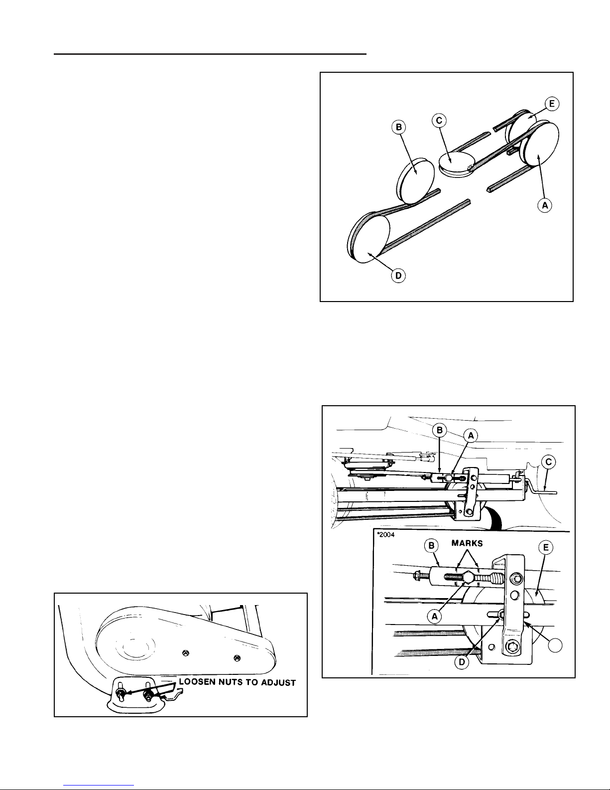
Figure 4. Belt Routing
A. V-Pulley
B. Idler Pulley
C. Electric Clutch Pulley (V-pulley)
D. Snowthrower Pulley (V-pulley)
E. Idler Pulley
Figure 5. Adjusting Belt Tension
A. Trunion D. Capscrew
B. Spring Tension Bracket E. Idler Pulley
C. Handle F. Pivot Bracket
F
BELT REPLACEMENT
1. Loosen the drive belt by turning the handle (C, Figure
5).
2. Remove the belt from the pulley (D, Figure 4) inside
the snowthrower and remove the snowthrower from
the tractor.
3. Loosen the lockwashers and nuts securing two belt
stops on idler pulleys (A and E, Figure 4).
4. Install new belt as shown.
5. Retighten belt stops and adjust the belt tension.
ADJUSTMENTS
Belt Tension Adjustment
See Figure 5.
1. With the snowthrower drive belt installed, trunion (A)
should be between marks on spring tension bracket
(B) for correct belt tension.
2. Turn belt tension handle (C) to move trunion forward
or rearward until within between marks.
3. If trunion cannot be placed between marks, loosen
capscrew (D) and reposition idler pulley (E) as necessary. The pivot bracket (F) should be perpendicular to
snowthrower hitch. Retighten capscrew (D) and
repeat step 2.
Skid Shoe Adjustment
On smooth surfaces such as concrete or asphalt, the
scraper bar should scrape the surface. On surfaces
such as gravel, the scraper bar should be set high
enough so that it will not pick up debris.
1. Loosen the nuts securing the skid shoes (see Figure
6).
2. Raise or lower the scraper bar to the desired height.
Use wood blocks to hold the snowthrower in position.
3. Set the skid shoes so that they are in contact with the
ground and tighten the skid shoe nuts.
Page 12

8
Adjustment
Lift Rod Adjustment
MANUAL LIFT MODELS
The lift lever can be placed in one of three notches and
is held in position by the lever latch. (see Figure 8).
When the lever latch is placed in notch 1 the lift lever
should be applying downward pressure on the
snowthrower. In position 2, the “float” position, the
snowthrower/plow should experience negligible upward
or downward pressure. Position 3 should raise the
snowthrower approximately 3 to 3-1/2 “ above the
ground.
ELECTRIC LIFT MODELS:
In the fully raised position the snowthrower should be 3
to 3-1/2” off the ground. In the fully lowered position, the
lift rod should slightly compress the spring (C, Figure 7)
creating downward pressure on the snowthrower. If the
snowthrower tilts excessively to one side you may want
to install the spring assist (see installation instructions).
The spring assist is not required on electric lift models.
NOTE: Always adjust the lift height before and after
adjusting the downward pressure.
Lift Height Adjustment
1. Place the lever latch in notch 3 or fully raise the electric lift (see Figure 8). The snowthrower should be
approximately 3 to 3-1/2” off the ground. If not, go to
step 2.
2. Lower the snowthrower and adjust the front set collar
(A, Figure 7) to achieve the correct lift height.
Downward Pressure Adjustment
1. Move the lever latch from notch 2 to notch 1 (See
Figure 8) or fully lower the electric lift.
2. The spring (C, Figure 7) should be slightly compressed applying downward pressure to the
snowthrower. If not, adjust the rear set collar (D,
Figure 7) to achieve the desired amount of downward
force. Do not over-compress the lift rod spring.
Figure 7. Adjusting Lift Rod
A. Front Set Collar
B. Rod Guide
C. Spring
D. Rear Set Collar
E. Spring Clip
Figure 8. Lift Lever Quadrant - Side View
Notch 1
Notch 2
Notch 3
CAUTION
Do not over-compress the lift rod spring. In addition
to providing downward pressure, the spring is an
elastic medium that absorbs shocks caused by
bumps and cracks in ground surfaces. Over-compressing the spring defeats this and could cause
damage to the unit.
Page 13

9
Troubleshooting
PROBLEM
1. Snowthrower auger does not rotate.
2. Auger does not stop when electric clutch is
disengaged.
3. Auger rotates, but snow is not thrown far
enough.
4. Scraper bar does not clean down to hard
surface.
5. Snowthrower picks up and throws stones on
gravel drive.
6. Tractor does not have sufficient traction.
7. Tractor not stable on sloping surfaces.
Locate the problem you’ve encountered in the chart below. Check the possible causes one at a time in the order listed. Correct any problems that are found and operate the snowthrower to see if you have eliminated the problem.
WARNING
To avoid serious injury, perform maintenance on the tractor or snowthrower only when the engine is
stopped, parking brake is set, and all moving parts have stopped. Always remove the ignition key before
beginning maintenance or adjustments to prevent accidental starting of the engine.
CAUSE/SOLUTION
A. Electric clutch not engaged. Engage electric clutch.
B. Foreign material is blocking auger. STOP engine. Remove key.
Unplug auger with piece of wood. Read WARNING on page 4.
C. Snowthrower drive belt slipping. Adjust drive belt tension.
D. Drive chain broken. Replace parts as required.
A. Electric clutch brake not operating properly. See your local
dealer. See WARNING under Stopping & Starting, page 4.
A. Engine RPM too slow. Operate engine at full speed.
B. Ground speed too fast. Use slow ground speed.
C. Snowthrower discharge spout clogged. STOP engine. Remove
key. Unplug discharge spout. Read WARNING on page 4.
A. Skid shoes not properly adjusted. Adjust skid shoes.
B. Lift rod out of adjustment. Adjust lift rod.
A. Skid shoes not properly adjusted for ground surface. Adjust
skid shoes.
B. Too much downward pressure on snowthrower. Raise
snowthrower slightly.
C. Lift rod out of adjustment. Adjust lift rod.
A. Tractor too light at rear wheels. Use wheel weights and chains.
A. Ground speed too fast. Reduce speed.
B. Tractor not properly weighted. See Recommended
Accessories, page 1.
C. Tire pressure incorrect. Front tires should be inflated to 20 psi
(138 kPa) for snowthrower use.
D. Slope grade too steep. See Operation On Slopes, page 3.
Page 14

10
Figure 9. Discharge Chute & Controls
A. Discharge Chute F. 1" Capscrew & Locknut
B. Rod Guide Liner G. Clip
C. Rod Guide H. Dis. Chute Control Rod
D. Pivot Bearing I. Notch
E. Support Arm J. 3-1/2" Capscrew & Locknut
K. Spacer
CAUTION
Do not let the pivot bearing (D, Figure 9) support
the weight of the control rod or the bearing could
be damaged.
SNOWTHROWER ASSEMBLY
Assemble Support Arm and Control Rod
1. See Figure 9. Attach the support arm (E) to the
frame with the 1" capscrews and locknuts (F) supplied.
2. See Figure 9. Place the the thin, plastic liner (B)
inside the rod guide (C). Place the rod guide (C) over
the discharge chute control rod (H) and loosely
attach the guide to the support arm (E) in either of
the top two mounting holes. Use the capscrew and
locknut (J) and spacer (K) provided.
3. See Figure 9. Install the discharge chute control rod
(H) through the plastic pivot bearing (D) on the auger
housing. Place a cotter pin into the lowest rod hole
on the inside of the housing, and spread the cotter
pin fully around the rod.
4. Pull the rod back so the cotter pin is resting against
the bearing (D), then insert a second cotter pin
through the rod, just above the bearing. Spread the
cotter pin fully around the rod.
5. Tighten the locknut and capscrew (J) securing the
control rod guide. Do not overtighten. This nut and
capscrew are used to set the control rod rotation
resistance.
Assemble Discharge Chute & Control Cable
1. See Figure 9. Install the discharge chute (A) so the
clip (G) on the housing is positioned in the notch (I).
Lubricate the discharge chute so it turns freely.
2. See Figure 10. With the discharge chute facing
slightly left, wind the cable around the control rod
spool. Wind it three turns on the rear part of the
spool so that the cable leaves the spool on the lower
edge as shown. Wind two turns on the front part of
the spool so the cable leaves the spool on the upper
edge as shown.
3. See Figure 10. Place the looped end of the cable
over the stud on the discharge chute. Place the small
flat washer (E) provided on the stud. Pull the other
end of the cable around the stud using locking pliers.
While holding the cable tight, install the cup washer
(B) (cup facing inward), lockwasher (C) and nut (D).
Tighten the nut and tape the cable end to the taut
section of the cable.
Figure 10. Control Cable
A. Cotter Pin C. Lockwasher
B. Cup Washer` D. Nut
E. Flat Washer
K
Regent Snowthrower Assembly
Page 15

11
Regent Snowthrower Assembly
Assemble Hitch Brackets and Up-Stops
Refer to Figure 11 for up-stop orientation.
1. Mount the hitch bracket to the inside of the
snowthrower and the up-stop bracket to the outside
of the snowthrower using capscrews and flange locknuts as shown in Figures 11 - 14.
Be sure the up-stop bracket is oriented correctly (see
Figure 11).
Figure 12. Hole Pattern - Left Side
Figure 13. Hole Pattern - Right Side.
NOTE: Support Arm Removed For Clarity
Figure 14. Install the Hitch Brackets and Stop
Brackets
A. Hitch Brackets C. Flange Locknut
B. Capscrew, 1" D. Up-Stop Bracket
Figure 11. Up-stop Bracket Orientation
Hitch Bracket
(Mounted On
Inside)
Hitch Bracket
(Mounted On
Inside)
Up-stop
Up-stop
Up-stop
Page 16

12
Figure 15. Spout Deflector
A. Washer, 5/16 F. Spacer
B. Knob G. Washer, 5/16
C. Deflector H. Screw, 5/16
D. Nut, 5/16 I. Carriage Bolt, 5/16
E. Lockwasher, 5/16
Assemble the Deflector
Refer to Figure 15.
1. Attach the deflector (C) to the discharge chute with
two screws (H), washers (G), spacers (F), washers
(A), lockwashers (E) and nuts (D).
2. Position the bolt (I) and washer (A), then thread the
knob (B) onto the bolt (I).
Figure 16. Installing Hitch to Front of Tractor
A. Hitch Bar D. Tractor Brackets
B. Hitch Pin E. Up-Stop Brackets
C. Safety Clip
HITCH INSTALLATION
NOTE: If your tractor is not equipped with the Large Lift
Lever, part no.1692623, install it at this time. Follow the
instructions supplied with the kit (a copy of the instruction sheet can be found in the back of this manual). The
rear hitch bracket, washers, and hairpin clips (B, C, D,
Figure 17) need to be installed with the left lever kit. The
pivot bar of the lift lever kit goes through the rear hitch
bracket and washers.
1. Increase front tire pressure to 20 psi (138 kPa) to
compensate for added weight. Be sure both tires
have equal pressure.
2. From the front of tractor, slide the hitch under the
tractor.
3. See Figure 16. Turn the wheels fully left and lift the
front hitch bar (A) up onto the tractor bracket (D).
Make sure it is seated fully into the tractor bracket.
Install the long hitch pin (B) through the up-stop
brackets (E, one on each side) and hitch. Secure the
pin with a safety clip (C).
E
D
Regent Hitch Installation
Page 17

13
Figure 17. Hitch Assembly
A. Hitch Assembly
B. Rear Hitch Bracket
C. Washers (Qty. 2)
D. Hairpin Clip (Qty. 2)
E. Pin
F. Spring Clip (Qty. 4)
G. Clevis Pin, 3/8 (Qty. 2)
H. Rod
I. Reflectors (Qty. 2)
J. Capscrew, 3/8-16 x 2
K. Spacer, 25/64 x 5/8 x 17/64
L. Spacer, 13/32 x 1 x 13/16
M. Nut, Whizlock, 3/8-16
N. Up-Stop Bracket (Qty. 2)
Attach reflectors (I) to rear lip
of seat deck. If snow cab is
installed, make sure reflectors
are not obstructed.
G
F
I
A
E
M
L
K
J
D
C
F
D
C
B
F
G
H
Figure 18. Installing Hitch to Rear Bracket
A. Rear Hitch Bracket F. Clevis Pin
B. Lift Lever Rod G. Capscrew, 3/8-16 x 2
C. Spring Clip H. Spacer, 25/64 x 5/8 x 17/64
D. Washer I. Spacer, 13/32 x 1 x 13/16
E. Hitch J. Nut, Whizlock, 3/8-16
4. See Figure 17. Install the rear hitch bracket (B), hair-
pin clips (D) and washers (C) onto the lift lever shaft,
if not done already.
5. Attach the hitch assembly to the rear hitch bracket
using the clevis pin (F) as shown in Figure 18.
6. Install the capscrew(G), spacers (I, H), and nut (J) as
shown in the Figure 18 inset.
The hitch assembly is now installed on the tractor and
you may proceed to Snowthrower Installation.
N
N
Regent-Hitch Installation
Page 18

14
SNOWTHROWER INSTALLATION
1. See Figure 19. Align snowthrower bracket (D) with
front tractor hitch arms (B). Lift snowthrower so that
up-stop brackets (E) rest on hitch arms (B).
2. Before attaching snowthrower bracket to the hitch,
install the belt from the hitch idler pulley (B, Figure
20) to the snowthrower pulley as shown in Figure 20.
Do not attempt to install the belt on electric clutch pulley at this time.
3. See Figure 19. Attach snowthrower bracket (D) to
hitch using clevis pins (B) and safety clips (A).
Figure 19. Snowthrower Installation
A. Safety Clips D.Snowthrower Bracket
B. Hitch Arms E. Up-Stop Brackets
C. Clevis Pin
Figure 20. Belt Routing
A. V-pulley C. Electric Clutch Pulley (V-Pulley)
B. Idler Pulley D. Snowthrower Pulley (V-Pulley)
E. Backside Idler Pulley
D
B
A
C
PTO Belt Installation and Trunion
Adjustment.
1. See Figure 21. To install the belt on the electric
clutch pulley, the trunion (A) on the tension spring
assembly (B) must be fully forward. Turn the handle
(C) to move the trunion forward and slacken the belt.
If the belt is still too tight, loosen the capscrew (D)
and slide the pulley (E) forward to further slacken the
belt. Install belt on electric clutch pulley. Refer to
Figure 20 for belt routing.
2. See Figure 21. Re-tighten the pulley (E) and capscrew (D) if they were loosened. Turn the handle (C)
so that the trunion (A) is centered between the marks
as shown.
NOTE: If trunion cannot be centered between marks,
loosen the trunion (A), loosen the capscrew (D) and
reposition the pulley (E) further rearward. Re-tighten capscrew (D) and center the trunion.
Figure 21. Belt Installation & Adjustment
A. Trunion D. Capscrew
B. Tension Spring Assembly.. E. Pulley
C. Handle
CAUTION
After snowthrower installation if the tractor hood is
opened, it will come into contact with the
snowthrower. To protect the hood finish cover the
discharge chute with a towel or blanket.
E
E
Regent-Hitch Installation
Page 19

15
Figure 22. Installing Lift Rod to Manual Lift Lever
A. Front Attachment Lift Rod C. Hair Pin Clip
B. Manual Lift Lever
A
B
C
Figure 23. Installing Lift Rod to Snowthrower
A. Rod Guide Assembly
B. Hair Pin Clip
Install lift rod to inside of bracket as shown.
Install the Lift Rod
1. Attach the lift rod assembly to the manual lift lever as
shown in Figure 22 and secure with a hairpin clip.
2. Install the front attachment lift rod to the snowthrower
as shown in Figure 23 and secure with a hair pin clip.
The rod guide assembly (A) may need to be removed
and oriented correctly.
Spring Assist Installation
NOTE: The parts described in the following steps (and
shown in Figures 24 & 25) are packaged with the hitch
assembly.
1. Place the snowthrower in the down position.
2. See Figure 24. Install the spring assist bracket (A)
using the capscrew (D), lockwasher (C), and nut (B)
as shown in Figure 24
3. Place spring assist lever (A Figure 25) in rearward
position. Install spring (B) directly onto spring assist
bracket (A) and on the spring assist lever. No chain
is required.
4. Rotate lever forward so that it travels “over center” to
the fully forward position.
Adjust, Lubricate, and Test Run
1. Adjust the Lift Rod-See Adjustments
2. Adjust the Skids-See Adjustments
3. Lubricate the Snowthrower-See Maintenance.
4. Install the reflectors on the on the rear lip of the seat
deck. If a snowcab is also installed, make sure the
reflectors are not obstructed.
5. Test run and recheck belt tension.
WARNING
Never release the spring assist lever unless the
snowthrower is in the fully raised position. The
spring is under tension when the snowthrower is
in the lowered position.
Figure 25. Spring-Assist Lever
A. Lever B. Spring
A
B
C
D
Figure 24. Spring Assist Bracket
A. Spring Assist Bracket C. Lockwasher
B. Nut D. Capscrew
A
B
Regent-Snowthrower Installation
Page 20

16
16
SNOWTHROWER ASSEMBLY
Assemble Support Arm and Control Rod
1. See Figure 26. Attach the support arm (E) to the
frame with the 1" capscrews and locknuts (F) supplied.
2. See Figure 26. Place the the thin, plastic liner (B)
inside the rod guide (C). Place the rod guide (C) over
the discharge chute control rod (H) and loosely attach
the guide to the support arm (E) in any of the three
mounting holes. Use the 3-1/2" capscrew, locknut
(J), and spacer (K) provided.
3. See Figure 26. Install the discharge chute control rod
(H) through the plastic pivot bearing (D) on the auger
housing. Place a cotter pin into the lowest rod hole on
the inside of the housing, and spread the cotter pin
fully around the rod.
4. Pull the rod back so the cotter pin is resting against
the bearing (D), then insert a second cotter pin
through the rod, just above the bearing. Spread the
cotter pin fully around the rod.
5. Tighten the locknut and capscrew (J) securing the
control rod guide. Do not overtighten. This nut and
capscrew are used to set the control rod rotation
resistance.
Assemble the Discharge Chute and Control
Cable
1. See Figure 26. Install the discharge chute (A) so the
clip (G) on the housing is positioned in the notch (I).
Lubricate the discharge chute so it turns freely.
2. See Figure 27. With the discharge chute facing slightly left, wind the cable around the control rod spool.
Wind it three turns on the rear part of the spool so
that the cable leaves the spool on the lower edge as
shown. Wind two turns on the front part of the spool
so the cable leaves the spool on the upper edge as
shown.
3. See Figure 27. Place the looped end of the cable
over the stud on the discharge chute. Place the small
flat washer (E) provided on the stud. Pull the other
end of the cable around the stud using locking pliers.
While holding the cable tight, install the cup washer
(B) (cup facing inward), lockwasher (C) and nut (D).
Tighten the nut and tape the cable end to the taut
section of the cable.
Figure 26. Discharge Chute& Controls
A. Discharge Chute F. 1" Capscrew & Locknut
B. Rod Guide Liner G. Clip
C. Rod Guide H. Dis. Chute Control Rod
D. Pivot Bearing I. Notch
E. Support Arm J. 3-1/2" Capscrew & Locknut
K. Spacer
Figure 27. Control Cable
A. Cotter Pin C. Lockwasher
B. Cup Washer` D. Nut
NOTICE
Do not let the pivot bearing (D, Figure 26) support
the weight of the control rod or the bearing could
be damaged.
Broadmoor-Snowthrower Assembly
K
Page 21

Assemble the Deflector
1. See Figure 28. Attach the deflector (C) to the discharge chute with two screws (H), washers (G), spacers (F), washers (A), lockwashers (E) and nuts (D).
2. Position the bolt (I) and washer (A), then thread the
knob (B) onto the bolt (I)
Assemble the Hitch Brackets and Spacers
1. Mount the hitch brackets and spacer to the inside of
the snowthrower capscrews and flange locknuts as
shown in Figures 29 - 31.
17
Broadmoor Snowthrower Assembly
Figure 28. Discharge Chute
A. Washer, 5/16 F. Spacer
B. Knob G. Washer, 5/16
C. Deflector H. Screw, 5/16
D. Nut, 5/16 I. Carriage Bolt, 5/16
E. Lockwasher, 5/16
Figure 29. Installing the Hitch Brackets and Spacers
A. Hitch Brackets E. Capscrew, 1-1/4"
B. Capscrew, 1" F. Lockwasher
C. Locknut, Flange G. Nut
D. Spacers
Figure 30 Hole Pattern - Left Side
Figure 31. Hole Pattern - Right Side.
NOTE: Support Arm Removed For Clarity
Hitch Bracket
(Mounted On
Inside)
Hitch Bracket
(Mounted On
Inside)
Spacer
(Mounted On
Inside)
Spacer
(Mounted On
Inside)
Page 22

HITCH INSTALLATION
NOTE: If your tractor is not equipped with the Large Lift
Lever, part no.1691832, install it at this time. Follow the
instructions supplied with the kit (a copy of the instruction sheet can be found in the back of this manual). The
rear hitch bracket, washers, and hairpin clips (B, C, D,
Figure 34) need to be installed with the left lever kit. The
pivot bar of the lift lever kit goes through the rear hitch
bracket and washers.
1. Increase front tire pressure to 20 psi (138 kPa) to
compensate for added weight. Be sure both tires
have equal pressure.
2. From the front of tractor, slide the hitch under the
tractor.
3. See Figure 33. Turn the wheels fully left and lift the
front hitch bar (A) up onto the tractor brackets (D).
Make sure it is seated fully into the tractor brackets.
Install the long hitch pin (B) through the bracket (bottom rear holes) and secure it with the safety clip (C).
Figure 33. Installing Hitch to Front of Tractor
A. Hitch Bar C. Safety Clip
B. Hitch Pin D. Tractor Brackets
D
18
Position shield 1/8"
from “T” on grille.
Figure 32. Heat Shield Installation
A. Heat Shield C. Clip
B. Carriage Bolt D. Lockwasher, 1/4
1/4-20 x 7/8 E. Nut, 1/4-20
CAUTION
The heat shield shown in Figure 32, is supplied
with the hitch assembly and must be installed
before installing hitch assembly. Damage to
snowthrower could occur if heat shield is not
installed.
Remove heat shield when removing snowthrower
and hitch assembly.
E
D
A
C
B
Install the Heat Shield
1. Install the heat shield as shown in Figure 32.
Position the shield 1/8” right of the “T” of “HOT”.
Broadmoor Hitch Installation
Page 23

Figure 34. Hitch Assembly..
Part No. 1692040 for Electric Lift
Part No. 1692041 for Manual Lift; Broadmoor/LT/2600/1600 Series
A. Hitch Assembly
B. Rear Hitch Bracket
C. Washers (Qty. 2)
D. Hairpin Clip (Qty. 2)
E. Pin
F. Spring Clip (Qty. 4)
G. Clevis Pin, 3/8 (Qty. 2)
H. Rod
I. Reflectors (Qty. 2)
Attach reflectors (I) to rear lip of
seat deck. If snow cab is installed,
make sure reflectors are not
obstructed.
Insert Pin “E” Through
the Top Hole
G
F
I
A
E
D
C
F
D
C
B
F
G
H
4. See Figure 34. Install the rear hitch bracket (B),
spring clips (D) and washers (C) onto the lift lever
shaft, if not done already.
5. See Figure 34 & 35. Secure the hitch assembly to
the rear bracket inserting pin “E” through the top hole
and securing with Spring Clip (F).
The hitch assembly is now installed to the tractor and
you may proceed to Snowthrower Installation.
19
Figure 35. Installing Hitch to Rear Bracket
A. Rear Hitch Bracket D. Washer
B. Lift Lever Rod E. Hitch
C. Spring Clip F. Clevis Pin
Broadmoor-Hitch Installation
Page 24

Figure 37. Belt Routing
A. V-pulley C. Electric Clutch Pulley (V-Pulley)
B. Idler Pulley D. Snowthrower Pulley (V-Pulley)
E. Backside Idler Pulley
20
SNOWTHROWER INSTALLATION
1. See Figure 36. Align snowthrower bracket (E) with
front tractor hitch arms (B). Lift snowthrower so that
spacers (A) rest on hitch arms (B).
2. Before attaching snowthrower bracket to the hitch,
install the belt from the hitch idler pulley (B, Figure
37) to the snowthrower pulley as shown in Figure 37.
Do not attempt to install belt on electric clutch pulley
at this time.
3. See Figure 36. Attach snowthrower bracket (C) to
hitch using clevis pins (C) and safety clips (D).
PTO Belt Installation and Trunion
Adjustment
1. See Figure 38. To install belt on the electric clutch
pulley, the trunion (A) on the tension spring assembly
(B) must be fully forward. If it is not, turn handle (C) to
move it forward. Install the belt on electric clutch pulley. Refer to Figure 37 for belt routing.
2. See Figure 38. Turn handle (C) so that trunion (A) is
centered between the marks as shown.
NOTE: If trunion cannot be centered between marks,
loosen capscrew (D, Figure 38) and reposition pulley
(E) rearward. Retighten capscrew (D) and center trunion.
Figure 36. Attaching the Snowthrower
A. Spacers D. Safety Clips
B. Hitch Arms E. Snowthrower Bracket
C. Clevis Pin
Figure 38. Belt Installation & Adjustment
A. Trunion D. Capscrew
B. Tension Spring Assembly. E. Pulley
C. Handle
Install the Lift Rod
1. Install the lift rod assembly to the manual lift lever as
shown in Figure 39 and secure with a hair pin clip.
2. Install the front attachment lift rod to the snowthrower
as shown in Figure 40 and secure with a hair pin clip.
The rod guide assembly (A, Figure 40) may need to
be removed and oriented correctly.
CAUTION
After snowthrower installation if the tractor hood is
opened, it will come into contact with the
snowthrower. To protect the hood finish cover the
discharge chute with a towel or blanket.
Broadmoor-Hitch Installation
Page 25

21
Figure 39. Installing Lift Rod to Manual Lift Lever
A. Front Attachment Lift Rod C. Spring Clip
B. Manual Lift Lever
A
B
C
Install the Spring Assist
NOTE: The parts described in the following steps (and
shown in Figures 42 & 41) are packaged with the hitch
assembly.
NOTE: 4-link chain replaces 3-link chain supplied with
snowthrower.
1. Place snowthrower in the down position.
NOTE: On single cylinder engines, the clevis pin (B,
Figure 41) must be installed to the bracket before mounting onto the tractor frame.
2. See Figure 41. Install the spring assist bracket (A)
into the underside of the frame as shown using a 11/4” long capscrew, lockwasher, and nut.
3. See Figure 41. Place the clevis pin (B) through the
spring assist bracket from the back. Install a flat
washer (C), the 4 link chain (D), another flat washer
(C), and safety clip (E) as shown.
4. Place snowthrower in fully raised position.
5. Rotate the spring assist lever (A, Figure 42) fully back
and install the spring (B) on the lever and through the
chain. See Figure 42.
7. Rotate lever forward so that it travels “over center” to
the fully forward position.
8. Lower the snowthrower.
Adjust, Lubricate, and Test Run
1. Adjust the Lift Rod- See Adjustments
2. Adjust the Skids-See Adjustments
3. Lubricate the Snowthrower-See Maintenance.
4. Install the reflectors on the on the rear lip of the seat
deck. If a snowcab is also installed, make sure the
reflectors are not obstructed.
5. Test run and recheck belt tension.
Figure 40. Installing Lift Rod to Snowthrower
A. Rod Guide Assembly
B. Hair Pin Clip
Install lift rod to inside of bracket as shown.
A
B
WARNING
Never pull spring-assist tension lever back unless
snowthrower is in fully raised position.
Figure 42. Spring-Assist Lever
A. Lever B. Spring
Broadmoor-Snowthrower Installation
Frame hole is located on front, left side; in front of engine
Figure 41. Spring Assist Bracket
A. Bracket D. 4-link Chain
B. Clevis Pin E. Safety Clip
C. Flat Washer
A
B
D
C
C
E
Page 26

22
SNOWTHROWER ASSEMBLY
Assemble the Support Arm and Control Rod
1. See Figure 43. Attach the support arm (E) to the
frame with the 1" capscrews and locknuts (F) supplied.
2. See Figure 43. Place the the thin, plastic liner (B)
inside the rod guide (C). Place the rod guide (C) over
the discharge chute control rod (H) and loosely attach
the guide to the support arm (E) in any of the three
mounting holes. Use the 3-1/2" capscrew, locknut
(J), and spacer (K) provided.
3. See Figure 43. Install the discharge chute control rod
(H) through the plastic pivot bearing (D) on the auger
housing. Place a cotter pin into the lowest rod hole on
the inside of the housing, and spread the cotter pin
fully around the rod.
4. Pull the rod back so the cotter pin is resting against
the bearing (D), then insert a second cotter pin
through the rod, just above the bearing. Spread the
cotter pin fully around the rod.
5. Tighten the locknut and capscrew (J) securing the
control rod guide. Do not overtighten. This nut and
capscrew are used to set the control rod rotation
resistance.
Assemble the Discharge Chute and Control
Cable
6. See Figure 43. Install the discharge chute (A) so the
clip (G) on the housing is positioned in the notch (I).
Lubricate the discharge chute so it turns freely.
7. See Figure 44. With the discharge chute facing slightly left, wind the cable around the control rod spool.
Wind it three turns on the rear part of the spool so
that the cable leaves the spool on the lower edge as
shown. Wind two turns on the front part of the spool
so the cable leaves the spool on the upper edge as
shown.
8. See Figure 44. Place the looped end of the cable
over the stud on the discharge chute. Place the small
flat washer (E) provided on the stud. Pull the other
end of the cable around the stud using locking pliers.
While holding the cable tight, install the cup washer
(B) (cup facing inward), lockwasher (C) and nut (D).
Tighten the nut and tape the cable end to the taut
section of the cable.
Figure 43. Discharge Chute & Controls
A. Discharge Chute F. 1" Capscrew & Locknut
B. Rod Guide Liner G. Clip
C. Rod Guide H. Dis. Chute Control Rod
D. Pivot Bearing I. Notch
E. Support Arm J. 1-1/2" Capscrew & Locknut
K. Spacer
Figure 44. Control Cable
A. Cotter Pin C. Lockwasher
B. Cup Washer` D. Nut
E. Flat Washer
CAUTION
Do not let the pivot bearing (D, Figure 43) support
the weight of the control rod or the bearing could
be damaged.
Landlord-Snowthrower Assembly
K
Page 27

23
Landlord-Snowthrower Assembly
Assemble the Deflector
1. See Figure 45. Attach the deflector (C) to the discharge chute with two screws (H), washers (G), spacers (F), washers (A), lockwashers (E) and nuts (D).
2. Position the bolt (I) and washer (A), then thread the
knob (B) onto the bolt (I).
Assemble the Hitch Brackets
1. Mount the hitch brackets to the inside of the
snowthrower capscrews and flange locknuts as
shown in Figures 46 - 48.
Figure 45. Deflector
A. Washer, 5/16 F. Spacer
B. Knob G. Washer, 5/16
C. Deflector H. Screw, 5/16
D. Nut, 5/16 I. Carriage Bolt, 5/16
E. Lockwasher, 5/16
Figure 46. Installing the Hitch Brackets
A. Hitch Brackets C. Flange Locknut
B. Capscrew, 1"
Figure 47. Hole Pattern - Left Side
Figure 48. Sketch 2. Hole Pattern - Right Side
NOTE: Support Arm Removed For Clarity
Hitch Bracket
(Mounted On
Inside)
Hitch Bracket
(Mounted On
Inside)
Page 28

24
Install the Heat Shield
1. Install the heat shield as shown in Figure 49.
Position the shield 1/8” right of the “T” of “HOT”.
Install the Lift Linkage and Rear Hitch
Bracket
ELECTRIC LIFT MODELS
1. Remove the hair pin clip (A, Figure 50) and slide the
shaft assembly (C) out far enough to remove the lift
tube assembly.
2. Push the shaft assembly back through the lift support
far enough to mount the rear hitch bracket (A, Figure
53), washers (D), and hairpin clips (C).
3. Push the shaft assembly (D, Figure 50) back through
the lift support and reinstall the hair pin clip (A).
4. Install the lift lever extension (D, Figure 51) onto the
shaft assembly (C, Figure 50) and secure to the lift
arm assembly (E, Figure 50) with the clevis pin (B,
Figure 51) and hair pin clip (C, Figure 51).
5. Install the front lift rod(A, Figure 51) into the lift lever
extension (D) and secure with a hair pin clip.
Figure 51. Electric Lift Models
A. Front Lift Rod
B. Clevis Pin
C. Hairpin Clip
D. Lift Lever Extension
Figure 49. Heat Shield Installation
A. Heat Shield C. Clip
B. Carriage Bolt D. Lockwasher, 1/4
1/4-20 x 7/8 E. Nut, 1/4-20
CAUTION
The heat shield shown in Figure 49, is supplied
with the hitch assembly and must be installed
before installing hitch assembly. Damage to
snowthrower could occur if heat shield is not
installed.
Remove heat shield when removing snowthrower
and hitch assembly.
E
D
A
C
B
Position shield 1/8"
from “T” on grille.
Figure 50. Electric Lift Assembly
A Hair Pin Clip D. Lift Support
B Lift Tube E. Lift Arm Assembly
C Shaft Assembly
C
D
B
A
E
Landlord-Snowthrower Assembly
Page 29

25
Landlord-Hitch Installation
Figure 54. Installing Lift Rod to Manual Lift Lever
A. Front Attachment Lift Rod C. Spring Clip
B. Manual Lift Lever
A
B
C
MANUAL LIFT MODELS
1. Loosen the hardware securing the lift guide bracket
(B, Figure 52) and remove the hair pin clip (C, Figure
52) from the left side of the lift lever assembly.
2. Partially remove the lift lever assembly from the
frame and install the rear hitch bracket (A, Figure 53),
washers (D), and hair pin clips (C).
3. Reinstall the lift lever assembly.
HITCH INSTALLATION
1. Increase front tire pressure to 20 psi (138 kPa) to
compensate for added weight. Be sure both tires
have equal pressure.
2. From the front of tractor, slide the hitch under the
tractor.
3. See Figure 55. Turn the wheels fully left and lift the
front hitch bar (A) up onto the tractor brackets (B).
Make sure it is fully seated into the tractor brackets.
Install the long hitch pin (C) through the bracket (bottom rear holes) and secure it with the safety clip (D).
4. See Figure 53. Install the rear bracket (A), spring
clips (C) and washers (D) onto the lift lever shaft, if
not done already.
5. Secure the hitch assembly (E, Figure 53) to the rear
bracket (A) inserting pin (F) through the top hole.
The hitch assembly is now installed to the tractor and
you may proceed to Snowthrower Installation.
Figure 53. Installing Hitch to Rear Bracket
A. Rear Hitch Bracket D. Washer
B. Lift Lever Rod E. Hitch
C. Hair Pin Clip F. Clevis Pin
Figure 52. Manual Lift Lever Assembly
A. Lift Lever Assembly. C. Hair Pin Clip
B Guide Bracket D. Shaft Assembly.
Figure 55. Installing Hitch to Front of Tractor
A. Hitch Bar C. Safety Clip
B. Hitch Pin D. Tractor Brackets
D
A
B
C
D
Page 30

26
SNOWTHROWER INSTALLATION
1. See Figure 57. Align snowthrower bracket (A) with
front tractor hitch (B).
2. Before attaching the snowthrower bracket to the
hitch, install the belt from the hitch idler pulley (B,
Figure 58) to the snowthrower pulley as shown in
Figure 58.
Do not attempt to install belt on electric clutch pulley
at this time.
3. See Figure 57. Attach snowthrower bracket (A) to
hitch using clevis pins (C) and safety clips (D).
Figure 57. Landlord/GT/2700/1700 Series
A. Snowthrower Bracket C. Clevis Pin
B. Hitch Arms D. Safety Clips
26
Figure 56. Hitch Assembly..
Part No. 1692040 for Electric Lift
A. Hitch Assembly..
B. Rear Support Assembly..
C. Washers (Qty. 2)
D. Hairpin Clip (Qty. 2)
E. Pin
F. Spring Clip (Qty. 4)
G. Clevis Pin, 3/8 (Qty. 2)
H. Rod
I. Reflectors (Qty. 2)
Attach reflectors (I) to rear lip of
seat deck. If snow cab is installed,
make sure reflectors are not
obstructed.
Install Pin “E” Through
the Bottom Hole.
G
F
I
A
E
D
C
F
D
C
B
F
G
H
CAUTION
After snowthrower installation if the tractor hood is
opened, it will come into contact with the
snowthrower. To protect the hood finish cover the
discharge chute with a towel or blanket.
Landlord-Snowthrower Installation
Page 31

27
Landlord -Snowthrower Installation
27
Figure 58. Belt Routing
A. V-pulley C. Electric Clutch Pulley (V-Pulley)
B. Idler Pulley D. Snowthrower Pulley (V-Pulley)
E. Backside Idler
Figure 60. Installing Lift Rod to Snowthrower
A. Rod Guide Assembly
B. Hair Pin Clip
Install lift rod to inside of bracket as shown.
A
B
Install the Belt
1. See Figure 59. To install the belt on the electric
clutch pulley, the trunion (A) on the tension spring
assembly (B) must be fully forward. If it is not, turn
handle (C) to move it forward. Install belt on electric
clutch pulley. Refer to Figure 58 for belt routing.
2. See Figure 59. Turn handle (C) so that trunion (A) is
centered between the marks as shown.
NOTE: If trunion cannot be centered between marks,
loosen capscrew (D, Figure 59) and reposition pulley
(E) rearward. Retighten capscrew (D) and center trunion.
Attach the Lift Rod to the Snowthrower
1. Install the front attachment lift rod to the snowthrower
as shown in Figure 60 and secure with a hair pin clip.
The rod guide assembly (A) may need to be removed
and oriented correctly.
Figure 59. Belt Installation & Adjustment
A. Trunion D. Capscrew
B. Tension Spring Assembly.. E. Pulley
C. Handle
Page 32

28
WARNING
Never pull spring-assist tension lever back unless
snowthrower is in fully raised position. Spring is
under tension when snowthrower is in lowered
position.
Figure 62. Spring-Assist Lever
A. Lever B. Spring
Landlord/GT/2700/1700 Series
Frame hole is located on front, left side; in front of engine
Install the Spring Assist
NOTE: The spring assist is not required on models
equipped with electric lift. However, if the snowthrower
leans to one side the spring assist can be installed to
correct this. The spring assist is required on all manual
lift models.
NOTE: The parts described in the following steps (and
shown in Figures 61 & 62) are packaged with the hitch
assembly.
NOTE: 4-link chain replaces 3-link chain supplied with
snowthrower.
1. Place snowthrower in the down position.
2. See Figure 61. Install the spring assist bracket (A)
into the underside of the frame as shown using a 11/4” capscrew, lockwasher, and nut.
3. See Figure 61. Place the clevis pin (B) through the
spring assist bracket from the back. Install a flat
washer (C), the 4 link chain (D), another flat washer
(C), and safety clip (E) as shown.
NOTE: On single cylinder engines, the clevis pin must be
installed to the bracket before mounting onto the tractor
frame.
4. Place snowthrower in fully raised position.
5. Rotate the spring assist lever (A, Figure 62) fully back
and install the spring (B) on the lever and through the
chain. See Figure 62.
6. Rotate lever forward so that it travels “over center” to
the fully forward position.
7. Lower the snowthrower.
Adjust, Lubricate, and Test Run
1. Adjust the Lift Rod- See Adjustments
2. Adjust the Skids-See Adjustments
3. Lubricate the Snowthrower-See Maintenance.
4. Install the reflectors on the on the rear lip of the seat
deck. If a snowcab is also installed, make sure the
reflectors are not obstructed.
5. Test run and recheck belt tension.
Landlord-Snowthrower Installation
Figure 61. Spring Assist Bracket
A. Bracket E. Safety Clip
B. Clevis Pin
C. Flat Washer
D. 4-link Chain
A
B
D
C
C
E
Page 33

29
Torque Specifications
TORQUE SPECIFICATIONS FOR
STANDARD MACHINE HARDWARE
(Tolerance ± 20%)
SIZE SAE GRADE #2 SAE GRADE #5 SAE GRADE #8
in/lbs
in/lbs in/lbs
ft/lbs Nm. ft/lbs Nm. ft/lbs Nm.
8-32 19 2.1 30 3.4 41 4.6
8-36 20 2.3 31 3.5 43 4.9
10-24 27 3.1 43 4.9 60 6.8
10-32 31 3.5 49 5.5 68 7.7
1/4-20 66 7.6 8 10.9 12 16.3
1/4-28 76
8.6 10 13.6 14 19.0
5/16-18 11 15.0 17 23.1 25 34.0
5/16-24 12 16.3 19 25.8 27 34.0
3/8-16 20 27.2 30 40.8 45 61.2
3/8-24 23 31.3 35 47.6 50 68.0
7/16-14 30 40.8 50 68.0 70 95.2
7/16-20 35 47.6 55 74.8 80 108.8
1/2-13 50 68.0 75 102.0 110 149.6
1/2-20 55 74.8 90 122.4 120 163.2
9/16-12 65 88.4 110 149.6 150 204.0
9/16-18 75 102.0 120 163.2 170 231.2
5/8-11 90 122.4 150 204.0 220 299.2
5/8-18 100 136 180 244.8 240 326.4
3/4-10 160 217.6 260 353.6 386 525
3/4-16 180 244.8 300 408.0 420 571.2
7/8-9 140 190.4 400 544.0 600 816.0
7/8-14 155 210.8 440 598.4 660 897.6
1-8 220 299.2 580 788.8 900 1,244.0
1-12 240 326.4 640 870.4 1,000 1,360.0
NOTES
1. These torque values are to be used for all hardware excluding: locknuts,
self-tapping screws, thread forming screws, sheet metal screws and socket
head setscrews.
2. Recommended seating torque values for locknuts:
a. for prevailing torque locknuts - use 65% of grade 5 torques.
b. for flange whizlock nuts and screws - use 135% of grade 5 torques.
3. Unless otherwise noted on assembly drawings, all torque values must meet
this specification.
Page 34

30
Standard Hardware
STANDARD
FASTENER
IDENTIFICATION
CHART
Hardware sizes given in the
illustrations throughout this
manual.
If a washer or nut is identified as
“washer, 1/2” or “nut, 1/2”, this
means the inside diameter is 1/2
inch
If a screw is identified as “screw,
1/2 x 2”, this means the shaft
diameter is 1/2 inch and the
shaft of the screw is 2 inches
long. If a screw is identified as
“screw, 1/2 - 16 x 2”, the number
“16” means that the screw has
16 threads per inch.
SAMPLE: SCREW IDENTIFICATION
HEX CAPSCREW IDENTIFICATION
Shown below
are actual size heads for standard screw sizes.
Example: a 1/4 screw has 7/16 head and thus requires a 7/16
wrench. To measure length, use the scale below.
WASHER AND NUT IDENTIFICATION
Place the washer or nut on the above scale to
determine the inside diameter. The actual inside
diameter can vary 1/16 inch. Use the scale for
comparison.
3/4” Head
screw with
1/2” S.D.
5/8” Head
screw with
7/16” S.D.
9/16” Head
screw with
3/8” S.D.
1/2” Head
screw with
5/16” S.D.
7/16” Head
screw with
1/4” S.D.
PLAIN WASHER
HEX CAPSCREW
CARRIAGE BOLT
LOCKWASHER
NUT
01234
1/2 1/2 1/2 1/2
1/4 1/4 1/4 1/4
3/4 3/4 3/4 3/4
Shaft
Diameter
SAMPLE: NUT IDENTIFICATION
Inside
Diameter
Screw Length
Shaft
Diameter
Screw 1/2 x 2
Shaft
Length
Nut, 1/2
Inside
Diameter
Page 35

31
1. Remove the mower deck.
2. Pry up and discard the two rear plastic ratchet fasteners holding the foot rest mat on the left and right
footrests.
3. Install the pivot bracket (A) to the underside of the left
footrest using capscrews (B) and nuts (C). Tighten
securely.
4. Assembly bracket (D) to the underside of the right
footrest using capscrews (B) and nuts (C). Tighten
securely.
5. Loosely assemble the guide (E) to the quadrant (F)
using two capscews (H), spacers (I), and nuts (C).
6. For snowthrower and plow use, install the rear hitch
bracket, hairpin clips and washers on the pivot rod
(parts supplied with hitch).
7. Slide the pivot rod through the pivot bracket (A) and
install the washer (J) and hairpin clip (K).
8. Mount the quadrant (F) onto the lift bracket (D).
9. Tighten the capscrews (H) and nuts (C) mounting the
guide (E) to the lift lever assembly. Be sure lift lever
assembly is securely clamping the foot rest and the
lever latch is unobstructed.
WARNING
Before performing any installation or adjustment,
turn off the engine and let the unit come to a complete stop. Remove the key and disconnect the
spark plug wire to prevent the unit from accidentally starting and causing personal injury.
Kit Contents:
Ref. Qty. Part No. Description
A 1 1704712 Pivot Bracket
B 4 1923325 Capscrew, 5/16-18 x 7/8
C 6 1924433 Nut, 5/16-18
D 1 1704713 Lift Bracket
E 1 1704715 Guide
F 1 1665591 Quadrant
G 1 1704718 Lift Lever Assy.
H 2 1921977 Capscrew, 5/16-18 x 1-1/4
I 2 1704716 Spacer
J 1 911386 Flat Washer
K 1 106788 Clip
Not shown
4 1704351 Fastener, Footrest Mat
Lift Lever Installation
G
H
F
E
I
C
B
C
D
A
B
K
J
Studs
Rear
Hitch Bracket
A
J
K
B
C
B
D
G
E
C
F
H
Installation
Instructions
Lift Lever Kits
Mfg. Nos. 1691832 & 1692623
BROADMOOR / 1600 / 2600 SERIES INSTALLATION - 1691832
Page 36

32
Kit Contents:
Ref. Qty. Part No. Description
A 1 1704715 Guide
B 1 1665591 Quadrant
C 3 1921977 Capscrew, 5/16-18 x 1-1/4
D 1 1921719 Capscrew, 5/16-18 x 2-1/2
E 1 1704716 Spacer,
11/32 ID x 3/4 OD x 7/16
F 3 1675795 Spacer
21/64 ID x 5/8 OD x 1/2
G 1 1674669 Spacer
25/64 ID x 5/8 OD x 1-5/32
H 4 1919438 Nut, Esna, Lock, 5/16-18
I 1 1704718 Lift Lever Assy.
1. Remove the mower deck.
2. Remove and retain the up-stop bracket and mounting
hardware.
NOTE: Reinstall the up-stop bracket for mower use.
3. Loosely assemble the guide (A) to the quadrant (B)
using capscrews (C, D), spacers (E, F, G), and nuts
(H).
4. Slide the lift lever pivot rod through the hole in the
right side of the frame.
5. Install the rear support assembly, washers, and hair
pin clips (supplied with snowthrower or dozer blade)
on the lift lever pivot rod.
6. Slide the lift lever pivot rod through the hole in the left
side of the frame.
7. Secure the quadrant to the frame using spacers (F),
capscrews (C), and nuts (H).
8. Tighten the guide plate (A) and quadrant (B) hardware making sure the lever latch movement is unobstructed.
WARNING
Before performing any installation or adjustment,
turn off the engine and let the unit come to a complete stop. Remove the key and disconnect the
spark plug wire to prevent the unit from accidentally starting and causing personal injury.
Lift Lever Installation
A
I
A
E
G
H
C
F
H
B
C
D
F
I
B
C
H
C
F
D
Rear Hitch Bracket
Frame
Bracket
Upstop Bracket Location
Up-Stop Bracket
Located Under
Right Side of
Frame
REGENT / 500 / 2500 SERIES INSTALLATION - 1692623
Form No. 1715019
Rev. 6/97
© 1997 Simplicity Manufacturing, Inc. All Rights Reserved
TP 200-2069-02-AT-SMA
MASimplicity Mfg. Inc.
500 N Spring Street / PO Box 997
Port Washington, WI 53074-0997 USA
Installation Instructions Lift Lever Kit
 Loading...