

Page 1

How to use this file...(Labels & Miscellaneous Documents)
————————————————————————————————————————————–––
Instructions for
Print Vendors (Paper Manuals)
Paper: * Various...
Press: * Various...
Bindery: * Various...
General: * This instruction page is NOT part of the document and must NOT be printed.
• Pages labeled with the text “THIS PAGE INTENTIONALLY BLANK” are placement pages ONLY,
and should NOT be printed.
• THIS document will most likely be a unique piece -- either a label or certificate or
other such miscellaneous format.
• EXACT specifications on the print & job specs should already be known to
you. In you are uncertain of what these specifications are, please contact
Simplicity Technical Publications.
• (Note: We will do our best to answer your questions concerning this job, but may need to transfer
you to another department within our company for additional specifications and job
requirements).
————————————————————————————————————————————–––
If you have further questions on how to utilize this file, please contact
Simplicity Technical Publications Department at (262) 284-8647.
Page 2

THIS PAGE INTENTIONALLY BLANK
Page 3
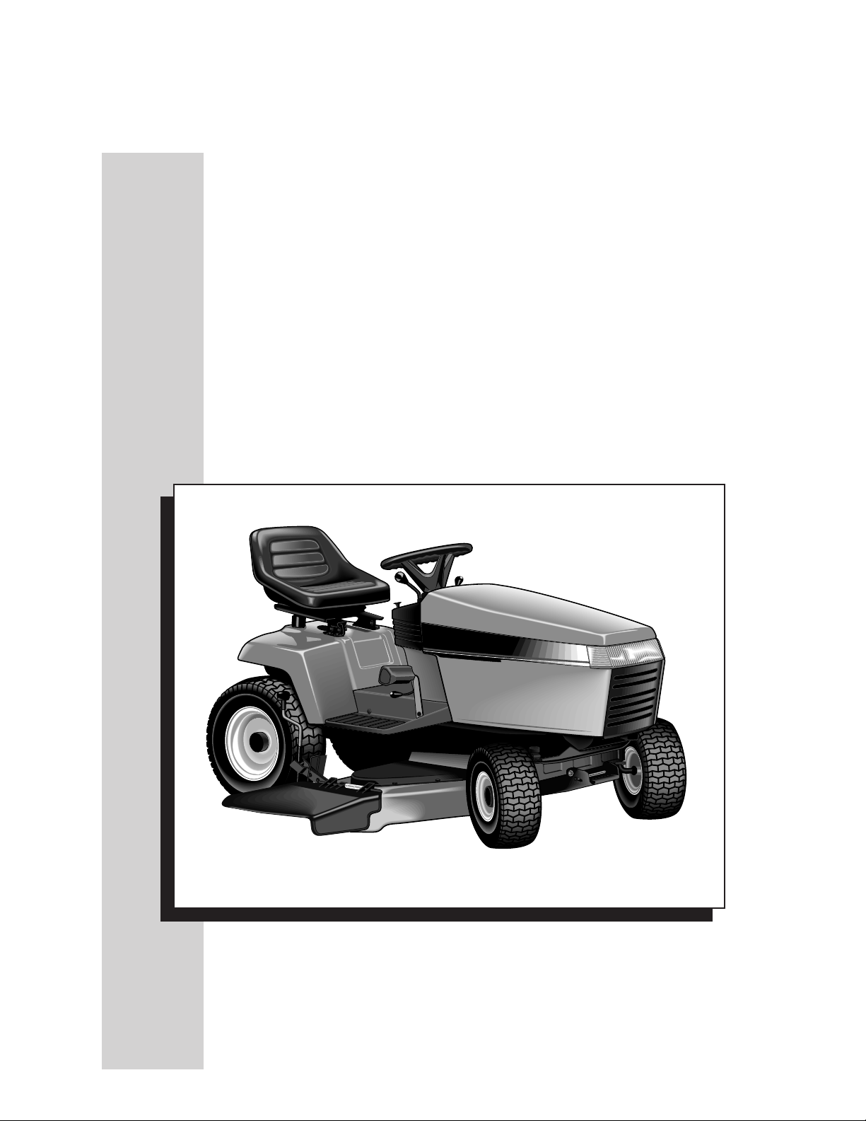
Repair Information
Neutral
Adjustments
For Hydrostatic Drive Tractors
Volume I
Fifth Edition (1975 – 1997 Model Year)
TP 500-1220-06-XX-SMA
Rev. 7/1999
Page 4

MANUFACTURING INC.
500 N. Spring Street / PO Box 997
Port Washington, WI 53074-0997 USA
www.simplicitymfg.com
© Copyright 1999, Simplicity Manfacturing, Inc.
All Rights Reserved. Printed in USA
Page 5

Table of Contents
Page
Section 1. Commercial Front-Cut Riders with Dual Eaton Model 7 Hydrostatic ................................................6
SIMPLICITY AGCO ALLIS MASSEY FERGUSON
CFC Series/Procut 3000 Series
1691969 - 20 HP
1691968 - 20 HP
1691967 - 18 HP
1691966 - 18 HP
1691965 - 16 HP
1691964 - 16 HP
1691846 - 20 HP
1691845 - 20 HP
1691844 - 18 HP
1691843 - 18 HP
1691842 - 16 HP
1691841 - 16 HP
1691975 - 20 HP
1691974 - 18 HP
1691973 - 16 HP
1691972 - 20 HP
1691971 - 18 HP
1691970 - 16 HP
1691882 - 16 HP
1691876 - 18 HP
Section 2. Large-Frame Tractors with Shaft Drive - Sundstrand Model 15
Hydrostatic (Peerless 2600-002 or 2600-008) ........................................................................... 11
SIMPLICITY AGCO ALLIS MASSEY FERGUSON
18 & 20 GTH & SunStar Series 1900 & Ultima Series 2900 Series
1692521 - 18 HP
1692456 - 20 HP
1692454 - 20 HP
1692135 - 20 HP
1692133 - 20 HP
1692131 - 18 HP
1691953 - 20 HP
1691926 - 20 HP
1691924 - 18 HP
1691710 - 20 HP
1691528 - 18 HP
1691381 - 20 HP
1691380 - 18 HP
1691357 - 16 HP
1691250 - 14 HP
1691018 - 20 HP
1691017 - 18 HP
1692523 - 18HP
1692460 - 20 HP
1692458 - 20 HP
1692141 - 20 HP
1692139 - 20 HP
1692137 - 18 HP
1691955 - 20 HP
1691397 - 18 HP
1691392 - 20 HP
1691391 - 18 HP
1691389 - 16 HP
1691387 - 14 HP
1691307 - 18 HP
1691020 - 20 HP
1691019 - 18 HP
1692525 - 18 HP
1692507 - 20 HP
1692505 - 20 HP
Section 3. Large-Frame Tractors with Belt Driven - Sundstrand Model 15 Hydrostatic.................................12
SIMPLICITY
Sovereign, 17GTH-L, AGCO ALLIS MASSEY FERGUSON
7000 & 7100 Series, 7790 900 & 700 Series 2800 Series
1692798 - 18 HP
1692796 - 18 HP
1692450 - 18 HP
1692143 - 18 HP
1691957 - 17 HP
1691717 - 17 HP
1691382 - 16 HP
1690890 - 18.5 HP
1690723 - 14 HP
1690640 - 19 HP
1690638 - 19 HP
1690572 - 17 HP
1690571 - 17 HP
1690570 - 16 HP
Section 4.
1690569 - 16 HP
1690480 - 17 HP
1690479 - 17 HP
1690478 - 16 HP
1690477 - 16 HP
1690473 - 12 HP
1690433 - 18 HP
1690431 - 18 HP
1690429 - 16 HP
1690427 - 16 HP
1690352 - 12 HP
1690342 - 16 HP
1690202 - 16 HP
1690006 - 16 HP
1692847 - 18 HP
1692845 - 18 HP
1692452 - 18 HP
1692144 - 18 HP
1691960 - 17 HP
1691718 - 17 HP
1691383 - 16 HP
1691139 - 18.5 HP
1691124 - 14 HP
1691122 - 16 HP
1690894 - 18.5 HP
1690727 - 14 HP
1690642 - 19 HP
1690575 - 16 HP
1690574 - 17 HP
1690519 - 17 HP
1690516 - 12 HP
1690367 - 18 HP
1690217 - 12 HP
1690214 - 12 HP
1690211 - 16 HP
1690076 - 12 HP
1690014 - 16 HP
1692852 - 18 HP
1692849 - 18 HP
1692503 - 18 HP
Tractors with Tuff Torq K215-A & HydroGear (Sundstrand) Hydrostatic, BDU-21L ........................
SIMPLICITY AGCO ALLIS MASSEY FERGUSON
Landlord, 18, 16GTH Series 1700 Series 2700 Series
1692631 - 16 HP
1692442 - 18 HP
1692440 - 16 HP
1692042 - 16 HP
1692006 - 18 HP
1692633 - 16 HP
1692448 - 18 HP
1692446 - 16 HP
1692044 - 16 HP
1692036 - 18 HP
1692501 - 18 HP
1
13
Page 6

Table of Contents (Continued)
Page
Tractors with Hydro-Gear 216-3010L Hydrostatic Transaxle...............................................................................................
15
SIMPLICITY AGCO ALLIS MASSEY FERGUSON
Landlord Series 1700 Series 2700 Series
1692788 - 18 HP
1692786 - 17 HP
1692784 - 16 HP
1692576 - 18 HP
1692572 - 16 HP
1692841 - 18 HP
1692839 - 17 HP
1692837 - 16 HP
1692578 - 18 HP
1692574 - 16 HP
1692854 - 17 HP
1692843 - 18 HP
1692580 - 18 HP
Section 5. Tractors with Eaton 850 Transaxle..........................................................................................................17
SIMPLICITY AGCO ALLIS MASSEY FERGUSON
17, 16GTH & 6500 Series 1800 Series
1691824 - 17 HP
1691766 - 16 HP
1691732 - 17 HP
1691263 - 16 HP
1691769 - 16 HP
1691682 - 17 HP
1691560 - 14 HP
1691471 - 16 HP
1691470 - 13 HP
Section 6. Tractors with Tuff Torq K60 Hydrostatic Transaxle............................................................................ 18
SIMPLICITY AGCO ALLIS MASSEY FERGUSON
Broadmoor, 12.5 & 16LTH Series 1600 Series
1692182 - 14 HP
1692073 - 12.5 HP
1692071 - 16 HP
1692184 - 14 HP
1692076 - 13 HP
1692075 - 16 HP
Tractors with HydroGear 311-0750/311-0800 Transaxle ................................................................................................ 19
SIMPLICITY AGCO ALLIS MASSEY FERGUSON
Broadmoor Series 1600 Series 2600 Series
1692776 - 16 HP
1692774 - 15 HP
1692772 - 14 HP
1692609 - 15 HP
1692528 - 15 HP
1692420 - 16 HP
1692416 - 14 HP
1692414 - 14 HP
1692283 - 16 HP
1692279 - 14 HP
1692261 - 12.5 HP
1692813 - 16 HP
1692811 - 15 HP
1692809 - 14 HP
1692613 - 15 HP
1692530 - 15 HP
1692436 - 16 HP
1692432 - 14 HP
1692430 - 14 HP
1692285 - 16 HP
1692281 - 14 HP
1692265 - 12.5 HP
1692817 - 16 HP
1692815 - 15 HP
1692499 - 16 HP
1692497 - 14 HP
Lawn Tractors with Eaton 750 or 751 Hydrostatic Transaxle........................................................................................21
SIMPLICITY AGCO ALLIS MASSEY FERGUSON
Broadmoor, 12.5 & 16LTH Series 1600 Series
1691886 - 12.5 HP
1691807 - 16 HP
Section 7.
1691795 - 12.5 HP 1691888 - 13 HP 1691817 - 13 HP
Lawn Tractors with HydroGear (Formerly Agri-Fab) Sundstrand BDU10S Transaxle...........................
25
SIMPLICITY AGCO ALLIS MASSEY FERGUSON
Regent, 12LT & 12RT Series 500 Series & 612H
1692156 - 12.5 HP
1692053 - 12 HP
1691931 - 12 HP 1692164 - 12.5 HP 1692057 - 12 HP
1691933 - 12 HP
2
Page 7

Table of Contents (Continued)
Page
Section 7.
Lawn Tractors with HydroGear 310 - 0500 Transaxle (With Hand Control)..............................................................27
1692403 - 12.5 HP 1692259 - 12.5 HP 1692263 - 12.5 HP1692412 - 12.5 HP 1692495 - 12.5 HP
Lawn Tractors with HydroGear 318-0500/322-0500 Transaxle (With Foot Control) ................................................28
1692354 - 14 HP 1692591 - 14 HP
Lawn Tractors with HydroGear 322-0650 Transaxle (With Foot Control) ..................................................................28
1692762 - 16 HP
(Continued)
SIMPLICITY AGCO ALLIS MASSEY FERGUSON
Regent Series 500 Series 2500 Series
SIMPLICITY AGCO ALLIS MASSEY FERGUSON
Regent Series 500 Series 2500 Series
1692588 - 14 HP
SIMPLICITY AGCO ALLIS MASSEY FERGUSON
Regent Series 500 Series 2500 Series
1692831 - 16 HP
1692835 - 16 HP
Section 8.
Lawn Tractors with Eaton Model 7 Hydrostatic & Peerless 1300 Series Transaxle ...........................
30
SIMPLICITY AGCO ALLIS MASSEY FERGUSON
5200 & 4200 Series 600 Series
1691649 - 16 HP
1691473 - 12.5 HP
1691362 - 16 HP
1691340 - 12 HP
1691271 - 12 HP
1691235 - 12.5 HP
1691234 - 12.5 HP
1691033 - 16 HP
1691032 - 16 HP
1691029 - 11 HP
1690936 - 16 HP
1690919 - 16 HP
1690912 - 11 HP
1690881 - 16 HP
1690853 - 16 HP
1690846 - 11 HP
1690810 - 16 HP
1690759 - 11 HP
1691479 - 12 HP
1691477 - 13 HP
1691475 - 16 HP
1691432 - 13 HP
1691276 - 12 HP
1691237 - 13 HP
1691236 - 13 HP
1691044 - 16 HP
1691043 - 16 HP
1691040 - 11 HP
1690960 - 16 HP
1690954 - 16 HP
1690947 - 11 HP
1690887 - 16 HP
1690875 - 16 HP
1690868 - 11 HP
1690763 - 11 HP
Section 9. Later Model Front-Cut Riders with Eaton Model 7 Hydrostatic....................................................... 31
SIMPLICITY AGCO ALLIS MASSEY FERGUSON
FC Series Front-Cut 1300 Series Front-Cut 2300 Series
1692375 - 16 HP
1692311 - 16 HP
1692309 - 12.5 HP
1692014 - 12.5 HP
1691656 - 16 HP
1691655 - 12 HP
1692375 - 16 HP
1692312 - 16 HP
1692310 - 12.5 HP
1692022 - 12.5 HP
1691660 - 16 HP
1691659 - 12 HP
1692512 - 16 HP
Section 10. Early Model Front-Cut Riders with Eaton Model 7 Hydrostatic ...................................................32
SIMPLICITY AGCO ALLIS MASSEY FERGUSON
SunRunner Series Vanguard Series
1691331 - 12 HP 1691336 - 12 HP
3
Page 8

Table of Contents (Continued)
Section 11. Mid-Engine Riding Mowers with HydroGear 311 - 0500 ................................................................33
SIMPLICITY AGCO ALLIS MASSEY FERGUSON
Coronet Series 400 Series 2400 Series
1692750 - 13 HP
1692515 - 12.5 HP
1692385 - 12.5 HP
1692130 - 12.5 HP
1692821 - 13 HP
1692519 - 12.5 HP
Transmission Purging
This procedure applies to the
following models:
Simplicity - Regent & Coronet Series
AGCO Allis - 500 & 400 Series
Massey Ferguson - 2500 & 2400 Series
The following is a purging procedure for
products that use the Hydro-Gear transmission. Use this procedure if air has become
trapped in the transmission during shipment,
storage, or during an oil change. Purge the
transmission if it lacks drive in forward or
reverse.
1. Park the tractor on a flat, level surface.
2. Place the hydro release lever in the PUSH
position by pulling rearward on the lever . The
lever is located under the rear right-hand corner
of the frame.
3. Start the tractor engine and run at low idle.
4. Move the ground speed control lever to the
neutral gate.
5. Return the control lever to the neutral gate.
6. Place the hydro release lever (A) in the DRIVE
position by pushing the lever fully forward.
7. Drive the tractor for at least five feet in forward
and reverse directions with full throttle and full
ground speed. Repeat this procedure three times
in the forward and reverse directions.
Repeat the above steps if the tractor has noisy or
erratic operation, lack of performance after
transmission warm up, or oil leakage from
transaxle vent tube.
1692399 - 12.5 HP
1692176 - 12.5 HP
1692491 - 12.5 HP
4
Page 9

Introduction
■ This manual assumes all clutch and brake adjustments have been made, and that
transmission control linkages are in good serviceable condition.
■ Worn parts, broken or weak springs, fasteners, and bushings should be replaced as
necessary before attempting to make adjustments.
■ It is possible during adjustments to place yourself in a position which is more
hazardous than when the unit is in normal operation.
■ Safety is a matter of common sense . . . a matter of thinking before acting.
■ Familiarize yourself with the product and pay special attention to all safety warnings.
■ These adjustments are meant to minimize cr eep when controls are placed in the neutral
position.
■ Hydrostatic transmissions should never be relied upon to hold a tractor in a parked
position. The parking brake should be set and engine stopped whenever leaving the
tractor.
NOTE: PUSHING THE TRACTOR BY HAND
1. Disengage the PTO and turn the engine off.
2. Move the transmission release lever to PUSH position.
The tractor can now be pushed by hand. T owing the tractor with another vehicle is not
recommended, as the transmission may be damaged.
WARNING
When making adjustment, keep hands, hair, clothing, and tools away from rotating
belts. Careless or improper attention may result in serious injury.
5
Page 10
Section 1.
Commercial Front-Cut Rider with Dual Eaton Model 7 Hydrostatic
Wheel-Steer Adjustments
Neutral
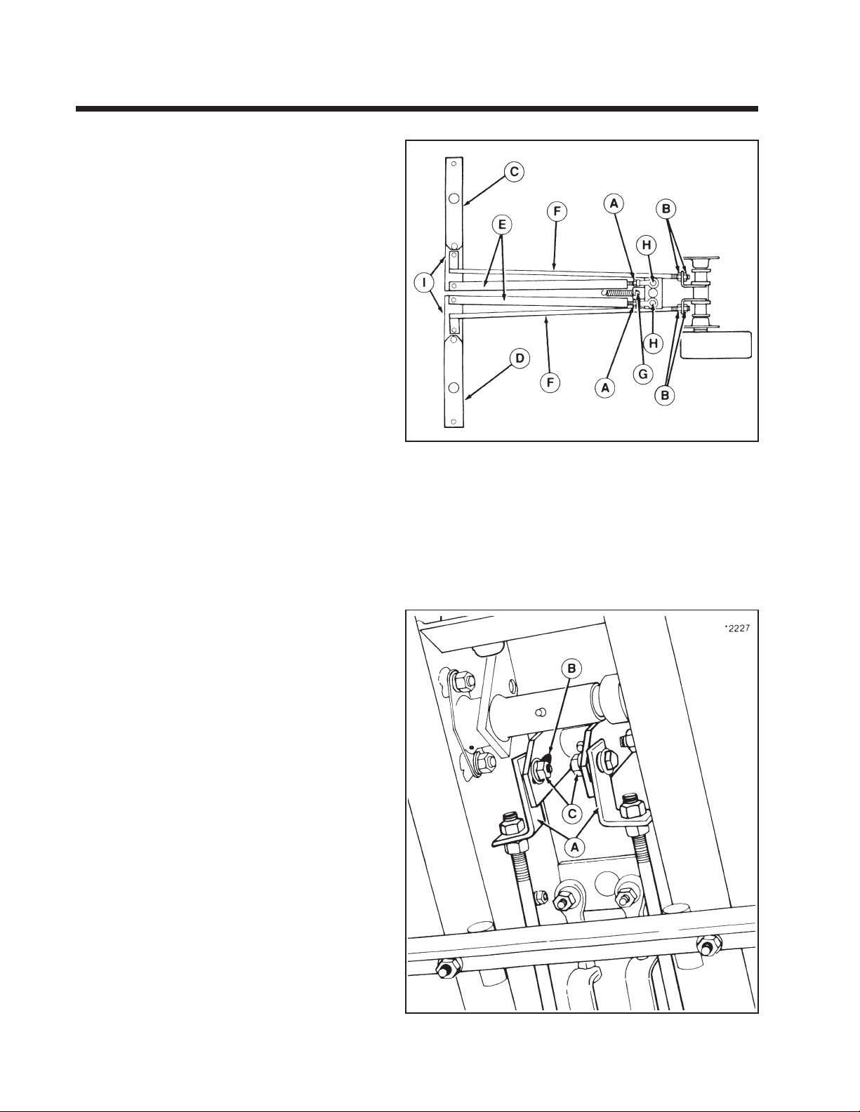
1. Make sure that the steering wheel is springcentered in the straight-forward position. If
spring pulls steering wheel off-center, loosen
the nut securing the anchor bolt (G) and move
bolt in slot until wheel is pointing straight
ahead. Retighten nut and recheck steering
wheel alignment.
2. Check the alignment of the rear edges of bars
(I, figure 1-1) and transmission control shafts
(C and D). Rear edges should be aligned as
shown in figure 1-1. To adjust linkage, first loosen
jamnuts (A), remove the nut securing the ball
joint (H), and rotate ball joint until alignment is
correct. Retighten all hardware.
3. Block frame so that wheels are off the ground.
Increase the engine RPM level and move foot
pedal forward and reverse several times. Spring
tension should return foot pedal to neutral.
4. If wheels rotate in neutral, loosen nuts
(B, figure 1-1) on each side of the hydro pump
linkage (F). Turn either front or rear nut until
wheel stops rotating.
5. Tighten nuts, making sure control rods do not
change position. This may take several times to
position rods at exact neutral.
6. Remove frame blocking and test operate.
Rider should not move with foot pedal in
neutral position.
Figure 1-1.
A. Steering Linkage Adjustment Nuts
B. Neutral Adjustment Nuts
C. Left Hand Transmission Control Shaft
D. Right Hand Transmission Control Shaft
E. Steering Linkage
F. Hydro Pump Linkage
G. Spring-Centering Bolt
H. Ball Joint
I. Bar
Transmission Speed Variation
If rider pulls to one side with the steering wheel in a
straight forward position, the hydro pump linkage
can be adjusted to correct for unequal pump output.
This adjustment limits the output of a faster hydro
pump at less than maximum forward speed. Refer to
“Forward Travel Stop Adjustment” for maximum
forward speed adjustment.
To adjust hydro pump linkage (A, figure 1-2), loosen
retaining hardware and move linkage upward in slot
(B) to reduce hydro pump output. Retighten flange
locknut (C) after adjustment is complete.
Figure 1-2.
A. Hydro Pump Linkage
B. Adjustment Slot
C. Flange Locknut
6
Page 11
Section 1. (Continued)
Commercial Front-Cut Rider with Dual Eaton Model 7 Hydrostatic
Ground Speed Control
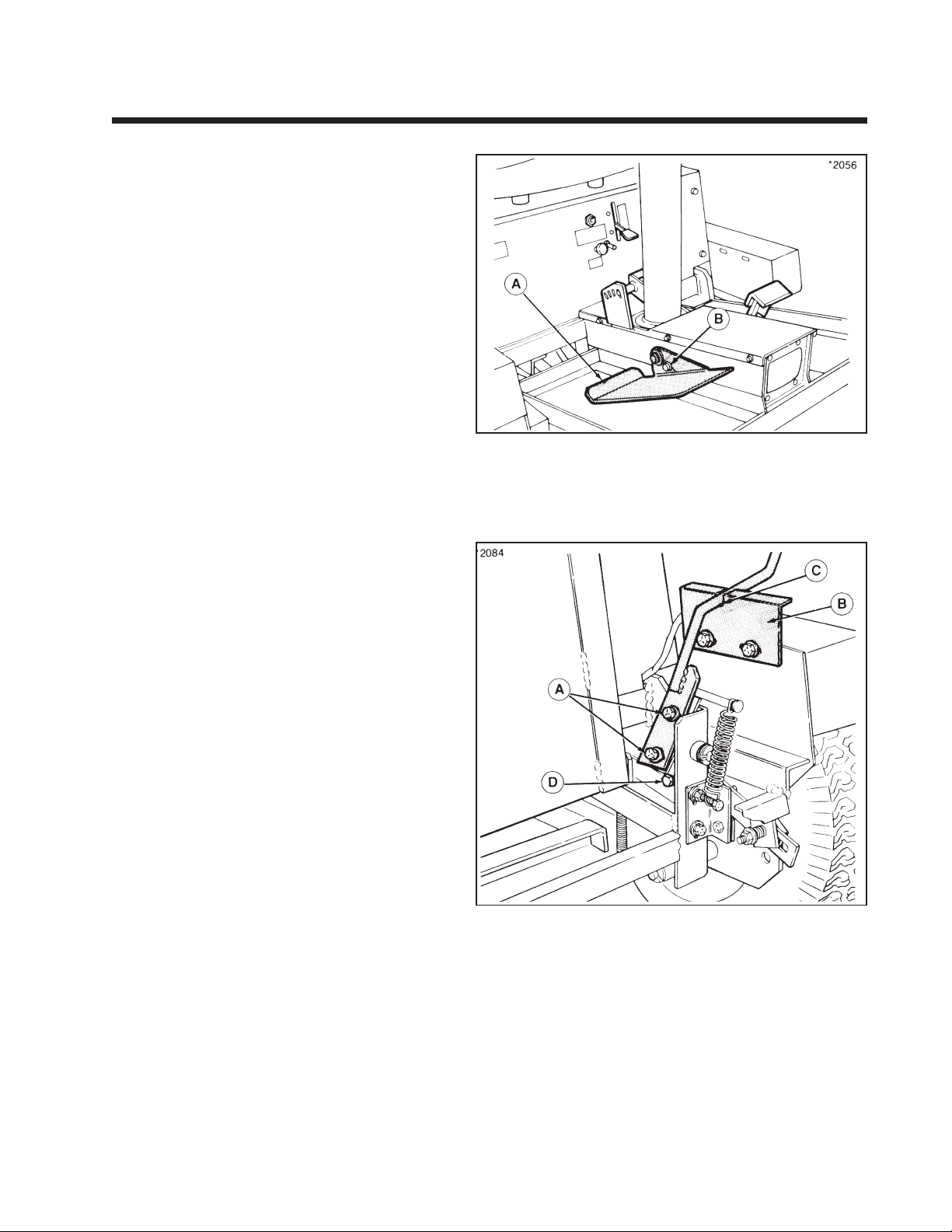
The position and angle of the foot pedal (A, figure
1-3) can be adjusted by loosening taptite screw (B)
and moving pedal in slot. This adjustment should
not affect rider speed or neutral adjustment.
Figure 1-3.
A. Foot Pedal
B. Adjustment Capscrew
Lever-Steer Adjustments
Control Levers
The control levers have slotted holes for mounting
and can be positioned for the most comfortable
operating position. When in neutral, the handles
should be opposite each other.
To adjust the angle of lever, loosen capscrew
(A, figure 1-4). Adjust lever position and retighten
capscrew. Neutral gate brackets (B) must be adjusted
so that new position of lever will be aligned with
neutral gate (C) when rider is in neutral.
In the operating position, handles should have about
1/2" between them so they will not contact each
other with the weight of the operator’s hands on
handles. To adjust distance, loosen locknut and turn
adjusting bolt (D) in or out. Retighten nut after
adjustment.
After handle adjustment, check the neutral adjustment to make sure there is no creep with levers in
neutral position. Readjust spring-centered lever
position. (Refer to following adjustments.)
Figure 1-4.
A. Capscrew
B. Brackets
C. Neutral Gate
D. Adjustment Bolt
7
Page 12
Section 1. (Continued)
Commercial Front-Cut Rider with Dual Eaton Model 7 Hydrostatic
Neutral
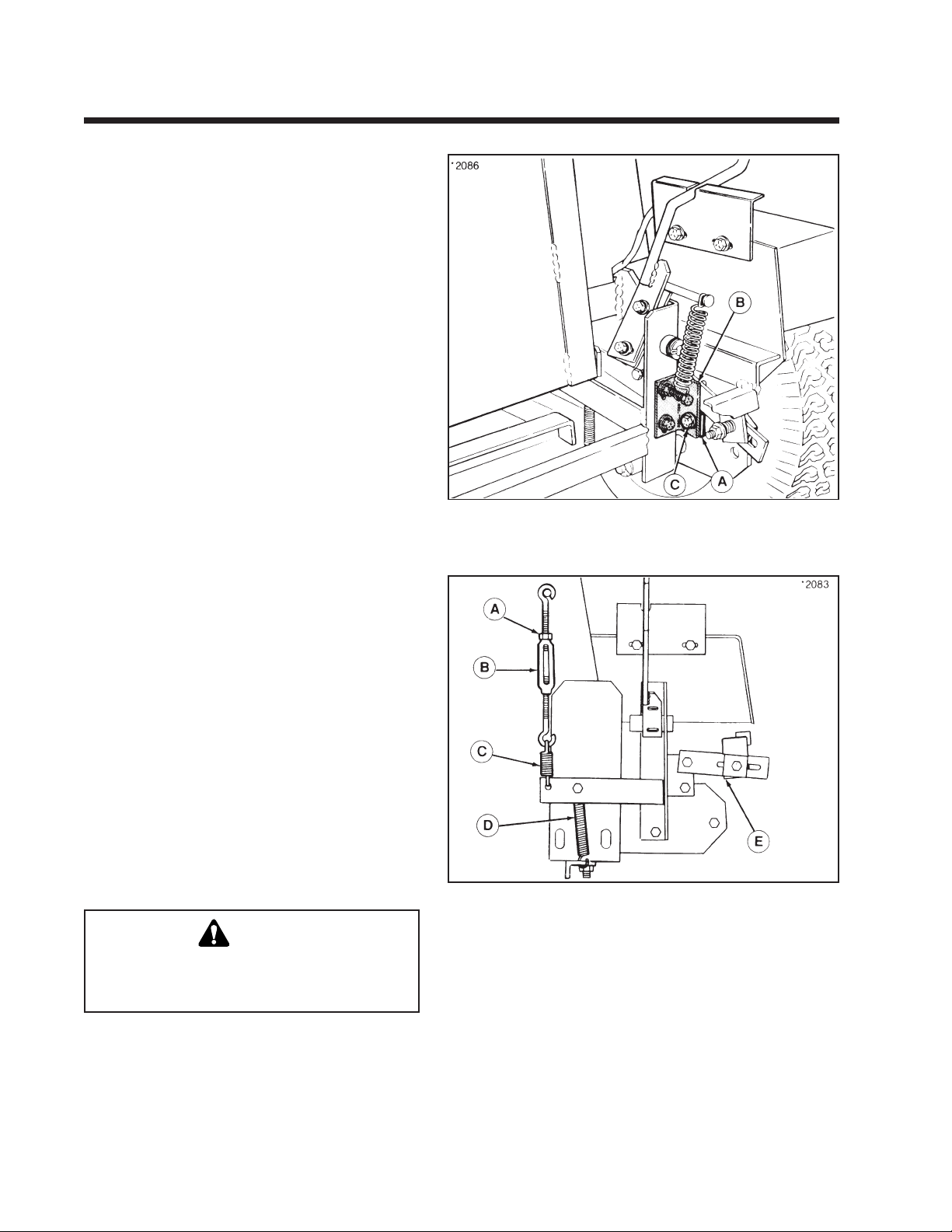
Exact neutral position of transmission control
linkage (A, figure 1-5) can be adjusted by changing
position of linkage on frame bracket (B). With
control levers in neutral position, wheels should not
turn in forward or reverse direction. To adjust
neutral:
1. Block frame up so both drive wheels are off the
ground.
2. Place weight in operator’s seat to start engine.
3. With control levers in neutral gate, start engine
and leave in fast throttle position. If either wheel
turns in forward or reverse direction, perform
steps 4 and 5.
4. Loosen capscrew (C) and nut securing transmission control linkage (A). Move linkage forward or
backwards until wheel stops moving.
5. Retighten hardware, making sure wheel does not
rotate after hardware is tightened. Repeat steps
for opposite wheel if necessary.
6. Shut engine off and remove weight from seat.
Lower rider to the ground.
Figure 1-5.
A. Transmission Control Linkage C. Capscrew
B. Frame Bracket
Spring-Centered Lever
Control levers should be adjusted so that levers
automatically return to neutral position when
released. Before performing adjustment, make sure
“Control Lever Adjustment” and “Neutral Adjustment” have been performed.
1. Block frame up so both drive wheels are off the
ground.
2. Place weight in operator’s seat to start engine. Do
not start engine.
3. Make sure that “Control Lever Adjustments” and
“Neutral Adjustment” are correct (refer to
preceding adjustments).
4. Loosen spring tension completely on friction pad
(refer to following adjustment).
5. Loosen nut (A, figure 1-6) on top of turnbuckle
(B) and adjust turnbuckle up or down.
WARNING
Do not adjust turnbuckle with engine running.
Hydro pump fan is too close to turnbuckle to
safely perform adjustment.
6. Restart engine and check control lever position.
Move control lever forward and backward and
check if lever returns to neutral position and
wheel does not rotate. If wheel rotates forward,
turnbuckle assembly must be lengthened (turnbuckle will move down). If wheels rotate backwards, turnbuckle assembly must be shortened
(turnbuckle will move up).
Figure 1-6.
A. Nut D. Stationary Spring
B. Turnbuckle E. Friction Pad
C. Tension Spring
7. Repeat turnbuckle adjustment until control lever automatically returns to neutral position. Tighten nut (A)
when adjustment is correct.
8. Tighten spring tension on friction pad (refer to following
adjustment).
9. Remove weight from seat and lower rider to the ground.
8
Page 13
Section 1. (Continued)
Commercial Front-Cut Rider with Dual Eaton Model 7 Hydrostatic
Friction Pad
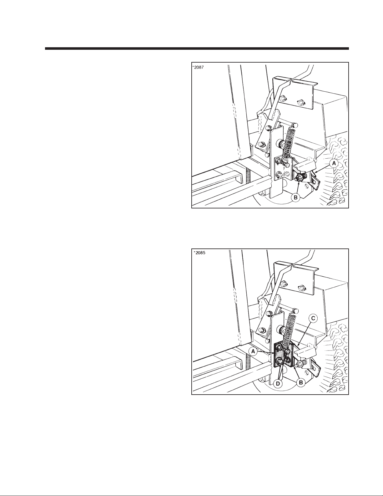
The amount of effort required to move control levers
can be adjusted by spring tension on friction pads
(A, figure 1-7). Reducing spring tension will make
the rider more responsive to control lever movement. Increasing spring tension will decrease
responsiveness and prevent rider movement from
becoming jerky, particularly near neutral range.
To adjust spring tension, turn adjusting nut (B) in to
increase tension or turn out to decrease tension.
Transmission Speed Variation
If one transmission is slower than the other with the
same control lever travel, the bracket (A, figure 1-8)
holding the transmission link (B) and friction bar (C)
can be adjusted. The bracket is slotted and is
adjusted by loosening the capscrews (D) and moving
the bracket. Raising the bracket will increase the
transmission speed. This adjustment must be made
by trial and error since the machine cannot be
operated while the adjustment is being made.
This adjustment will not affect lever position, neutral
adjustment, or spring-centered lever adjustment.
Figure 1-7.
A. Friction Pad
B. Adjusting Nut
Figure 1-8.
A. Bracket
B. Transmission Link
C. Friction Bar
D. Capscrews
9
Page 14
Section 1. (Continued)
Commercial Front-Cut Rider with Dual Eaton Model 7 Hydrostatic
Wheel- & Lever-Steer
Forward Travel Stop
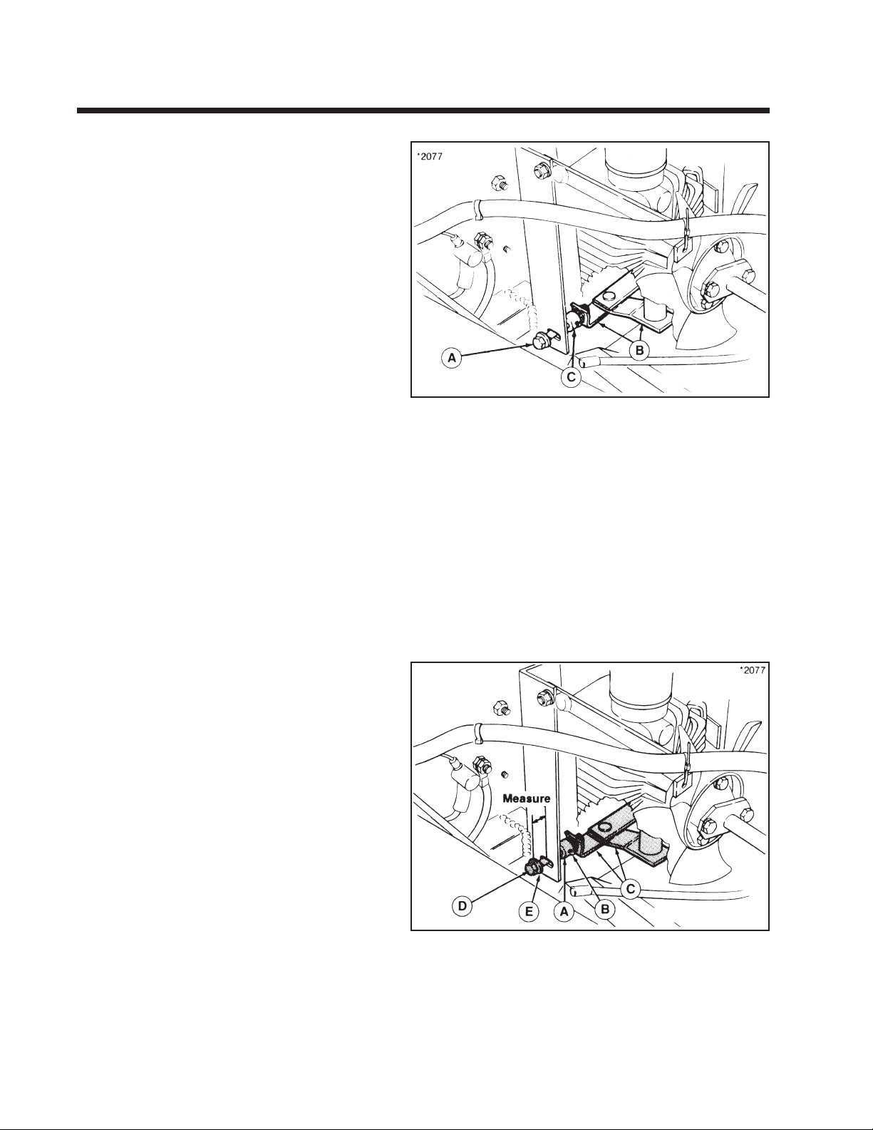
The adjustment bolt (A, figure 1-9) can be rotated to
limit the maximum output speed of each hydro
pump so that the rider will travel in a straight
direction at full forward ground speed. For hydro
output speed variation at less than full forward
position, refer to “Transmission Speed Variation
Adjustment”.
For double-chain reduction models, turn the bolt all
the way out. With ground speed control set to full
forward position, turn the bolt in until it contacts the
frame. Turn the bolt an additional 1/2 turn so that
internal hydro pump components are not used as the
forward travel stop.
For single-chain reduction models, adjust the bolt so
drive wheels are turning 130 rpm maximum.
The left or right adjustment bolt can be turned
inward an additional amount required to limit the
output speed of a faster hydro pump if there is
noticeable difference at maximum forward speed.
If unit is equipped with set collar (C, figure 1-9),
turning the adjustment bolt will affect the reverse
travel stop. (Some early model lever-steer units did
not require set collar.) Perform the “Reverse Travel
Stop Adjustment” to reposition the set collar if
forward travel stop is adjusted.
Figure 1-9.
A. Adjustment Bolt
B. Hydro Input Linkage
C. Set Collar
Reverse Travel Stop
The maximum reverse speed of each hydro pump is
controlled by the position of a set collar (A, figure 1-
10) that limits the travel of hydro input linkage (C).
Adjust the forward travel stop, if necessary, before
adjusting reverse travel stop.
The factory pre-set position of the set collar limits the
reverse speed of rider to 3.5 mph. If the set collar
position is changed due to adjusting the forward
travel stop or service work, set collar (A) should be
repositioned so that there is 1-1/4" (double-chain
reduction models) or 5/8" (single-chain drive
models) between flat washer (E) and frame bracket
with ground-speed control in the full reverse
position.
Figure 1-10.
A. Set Collar D. Capscrew
B. Setscrew E. Flat Washer
C. Hydro Input Linkage
10
Page 15
Section 2. Large-Frame Tractors with Shaft Drive -
Sundstrand Model 15 Hydrostatic (Peerless 2600-002 or 2600-008)
Neutral Adjustment
WARNING
Before performing maintenance, lower the attachment,
shut off engine and remove key, disengage PTO switches
and set parking brake.
If the tractor creeps forward or back when ground speed
control lever is in NEUTRAL, adjust as follows.
1. Remove the upper right-hand panel by removing three
screws.
2. Place blocks in front of front tires.
3. Place jack under rear draw bar and raise tractor so that
rear wheels are off the ground. Place jack stands under
axles so tractor is secure.
NOTE: Be sure jack stands do not contact tires.
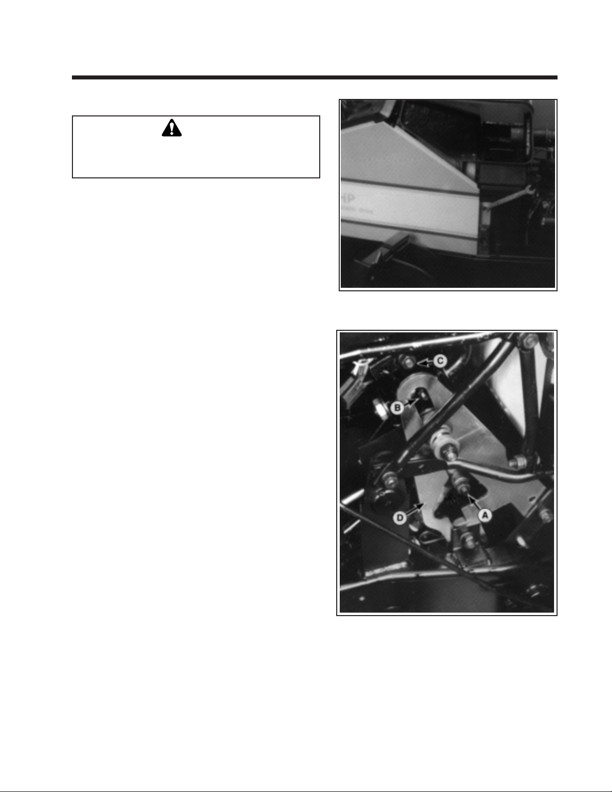
Figure 2-1.
4. Apply the parking brake.
5. Loosen three nuts (A, B, C). Move the ground speed
control lever fully to rear, then tighten nut (C)
(temporarily).
6. Release the parking brake. Put lever in neutral.
7. Start the tractor engine (hold in seat switch) and apply
full throttle. Move ground speed control lever forward
until wheels rotate forward. Move lever back until wheels
stop turning. Shut off engine.
8. Make sure nut (A) is loose, then apply parking brake.
9. As brake is applied, the cam lever (D) will drop down.
Align spacer on the nut (A) as it drops. Then tighten the
nut (A) being sure no linkage moves while tightening.
Loosen nut (C) and move speed control lever into neutral
gate. Tighten nuts (B and C).
10. To test, release parking brake and start engine. Move
lever fully forward and rearward. Wheels must stop in
neutral. Stop the engine.
11. Reinstall the dash panel.
Figure 2-2.
A. Nut
B. Nut
C. Nut
D. Cam Lever
11
Page 16
Section 3.
Large-Frame Tractors with Belt Driven - Sundstrand Model 15 Hydrostatic
Neutral Adjustment
If the tractor creeps forward or back when the hydrostatic control lever is in neutral, adjust as follows:
CAUTION
Always stop engine before leaving operator's
position. Do not perform adjustment with engine running.
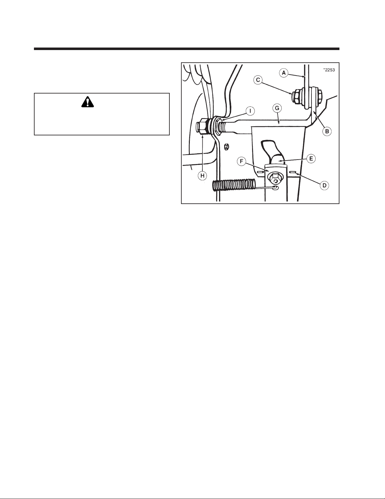
1. Park tractor on level ground, make sure hydrostatic control lever is firmly seated in the neutral
notch of quadrant, stop engine and set parking
brake.
2. Raise the seat deck and check if the pump control
arm roller (E, figure 3-1) is exactly centered with
the centering mark (D). If not, loosen bolt (C) and
move the control cam (B) until centering mark (D)
is centered on roller (E). Tighten the bolt (C).
3. Lower the seat deck, get in operator's seat, start
engine and release parking brake. If tractor still
creeps with hydrostatic control lever in neutral,
note which direction it creeps and proceed with
next steps.
4. Stop the engine, set parking brake, and raise seat
deck. Loosen the jam nut (H) on end of cam pivot
shaft (G). If tractor creep had been in reverse,
turn adjusting nut (I) 1/8 to 1/4 turn clockwise
when viewed from right side of tractor. If tractor
creep had been forward, turn nut 1/8 to 1/4 turn
counterclockwise. Lock jam nut, lower seat deck,
get in operators seat, start engine, and release
parking brake. If tractor still creeps, repeat step 4,
turning nut (I) a little at a time until no creep
occurs.
Figure 3-1. Hydrostatic Neutral Adjustment
A. Control Strap
B. Control Cam Assy. F. Pump Control Arm
C. Bolt G. Cam Pivot Shaft
D. Centering Mark H. Jam Nut
E. Pump Control Arm Roller I. Adjusting Nut
12
Page 17
Section 4.
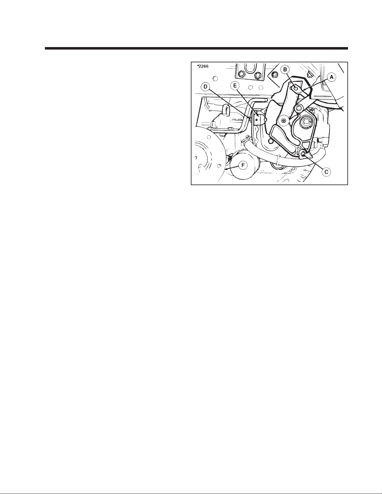
Tractors with Tuff Torq K215-A & HydroGear (Sundstrand) Hydrostatic, BDU-21L
Neutral Adjustment (Early Model Only)
1. Park tractor on level surface. Shut off electric
clutch switch and engine. Do not apply parking
brake. Make sure transmission control lever is in
neutral and the hydro release valve is in the
“DRIVE” position.
2. Raise rear of tractor off ground with a suitable
hoist or floor jack. Remove the right-hand rear
wheel. Install safety jackstand underneath righthand footrest and block front wheels. Lower the
tractor until the left-hand tire is on the ground.
3. Loosen nut securing shift rod (A, figure 4-1) at
top of speed control lever (B).
4. Loosen nut securing bottom of speed control
lever (C) to support bracket.
5. Loosen nut (D) securing ball retainer (E) to
support bracket.
6. Start engine and run at full throttle.
7. Rotate ball retainer (E) until drive hub rotates in a
clockwise (forward) direction. Turn the ball
retainer back until the drive hub stops rotating.
Ball retainer can be rotated with a pliers or use a
1/4" rod or #2 Phillips screwdriver into hole in
ball retainer.
8. Tighten nut (D) securing ball retainer (E).
9. Depress clutch/brake pedal fully and apply
parking brake. Turn the tractor engine off.
10. Tighten both nuts securing the top and bottom of
the speed control lever (B & C).
11. Release the parking brake and restart the engine.
Run the engine at full throttle and check for drive
hub rotation.
a. Wheel hub (F) may rotate in a counterclock-
wise (reverse) direction due to internal relief
valve. If hub can be held by hand to stop
rotation, adjustment is satisfactory. If hub
cannot be held by hand, loosen the nut (D) and
adjust ball retainer (E) until hub rotation stops.
Retighten nut (D) and recheck for hub rotation.
b. If wheel hub rotates in a clockwise (forward)
direction, loosen the nut (D) and adjust ball
retainer (E) until hub rotation stops. Retighten
nut (D) and recheck for hub rotation.
12. When adjustment is correct, stop the tractor
engine and reinstall the rear wheel. Remove the
tractor from the jackstands.
Figure 4-1.
A. Shift Rod
B. Speed Control Lever (Top)
C. Speed Control Lever (Bottom)
D. Nut
E. Ball Retainer
F. Wheel Hub
13
Page 18
Section 4. (Continued)
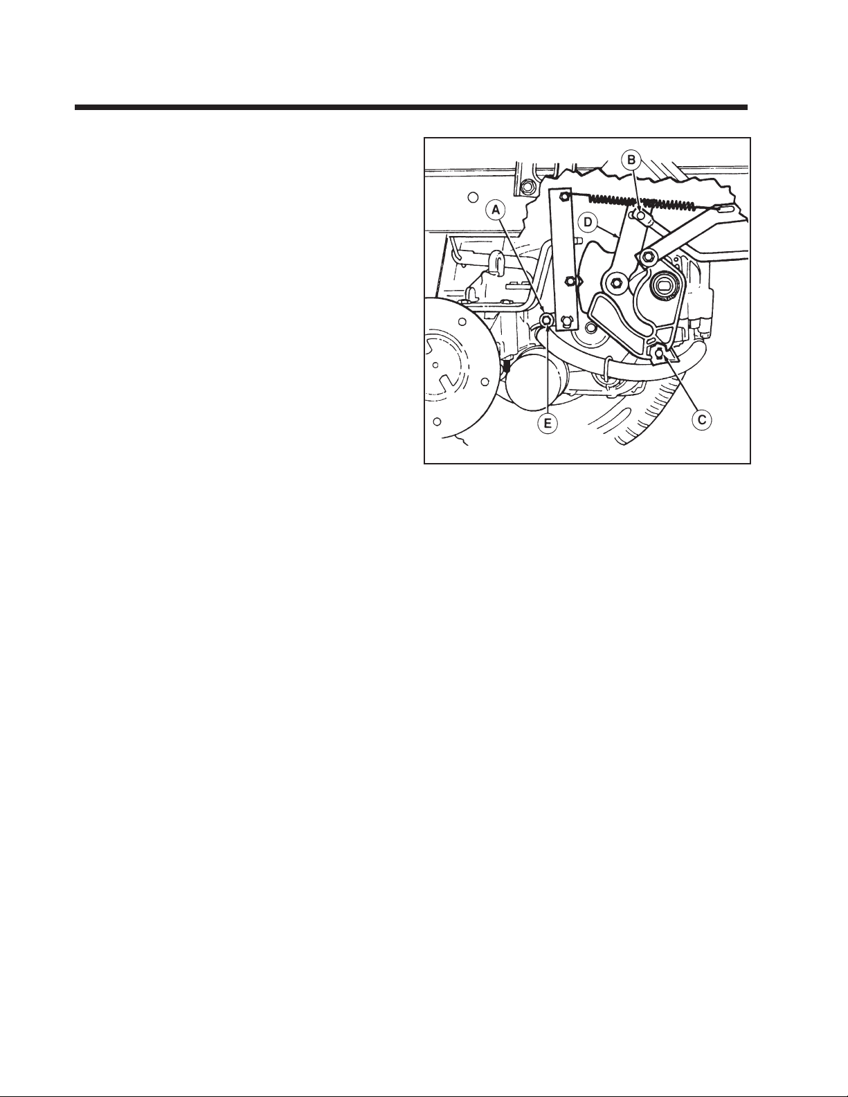
Tractors with Tuff Torq K215-A & HydroGear (Sundstrand) Hydrostatic, BDU-21L
Late Models - Early Models with 1686602 kit installed
1. Perform neutral adjustment as follows:
a. Put tractor in Neutral. Make sure tow valve is
securely in the drive (UP) position or adjustment
will not be accurate. Lower the tractor so that left
rear wheel is on the ground.
b. Put weight in seat. Start tractor and run engine at
half-throttle.
Note: After installation of kit parts, hardware at locations
B, C, and E, figure 4-2, must be loose before adjustments
are made.
c. Use 3/4" open end wrench to turn hex adjuster (A,
figure 4-2). Turn until rotation of right axle stops.
Tighten nut.
d. Shut off engine. Apply parking brake. Tighten nut
(C) at bottom of speed control lever (D) and then
tighten nut (B) at top of speed control lever.
e. Disengage parking brake and start tractor. Move
the ground speed control lever from Forward and
Reverse into the Neutral gate.
f. If there is minimal rotation of right rear axle,
slightly loosen nut (E, figure 4-2) on hex adjuster.
Turn hex adjuster just slightly (turn counterclockwise to correct forward rotation and turn clockwise
to correct reverse rotation) until axle stops.
If there is more than slight rotation of rear axle,
repeat steps a-d.
g. Move the ground speed control lever from Forward
and Reverse into the Neutral gate by depressing the
brake pedal (return-to-neutral pedal). Check that
the shift control lever drops into the neutral gate on
dash and that there is no rear axle rotation . Note
that slight rearward (counterclockwise) rotation of
axle will stop within a few seconds. This small
amount of rotation will not cause tractor creeping
and does not require adjustment.
h. When adjustment is correct, tighten adjustment nut
(E) to 70-75 in. Ibs.
2. Make sure all hardware is tightened on installed
kit parts.
3. Reinstall rear wheel.
4. Remove jackstands and lower tractor.
5. Start tractor and check operation of shifting linkage
and return-to-neutral. Readjust neutral as required.
*2518
Figure 4-2.
A. Hex Adjuster
B. Top Nut Location
C. Bottom Nut Location
D. Speed Control Lever
E. Nut
14
Page 19
Section 4. (Continued)
Tractors with HydroGear 216-3010L Hydrostatic Transaxle
Neutral Adjustment
Perform the following adjustment if the shift lever must be
moved out of the neutral gate to prevent forward or reverse
tractor movement. (With the clutch/brake pedal released, a
small amount of travel in the shift lever may be required to
fully stop tractor.)
1. Position unit on flat, level ground. Make sure the shift
lever is positioned in the neutral gate.
2. Raise the rear of tractor off ther ground, and support it
securley with jackstands so that the rear wheels are free to
rotate.
3. Start the unit and move the shift lever until the rear
wheels stop moving. Shut off tractor engine, leaving shift
lever in position.
WARNING
When Making adjustment, keep hands, hair, clothing, or
tools away from rotating belts. Grasp cam lever at base to
keep hand several inches below belt rotating around
idler pulley assembly. Careless or improper attention
any result in serious injury.
FRONT
➜
E
D
C
Viewed From Bottom Looking Up
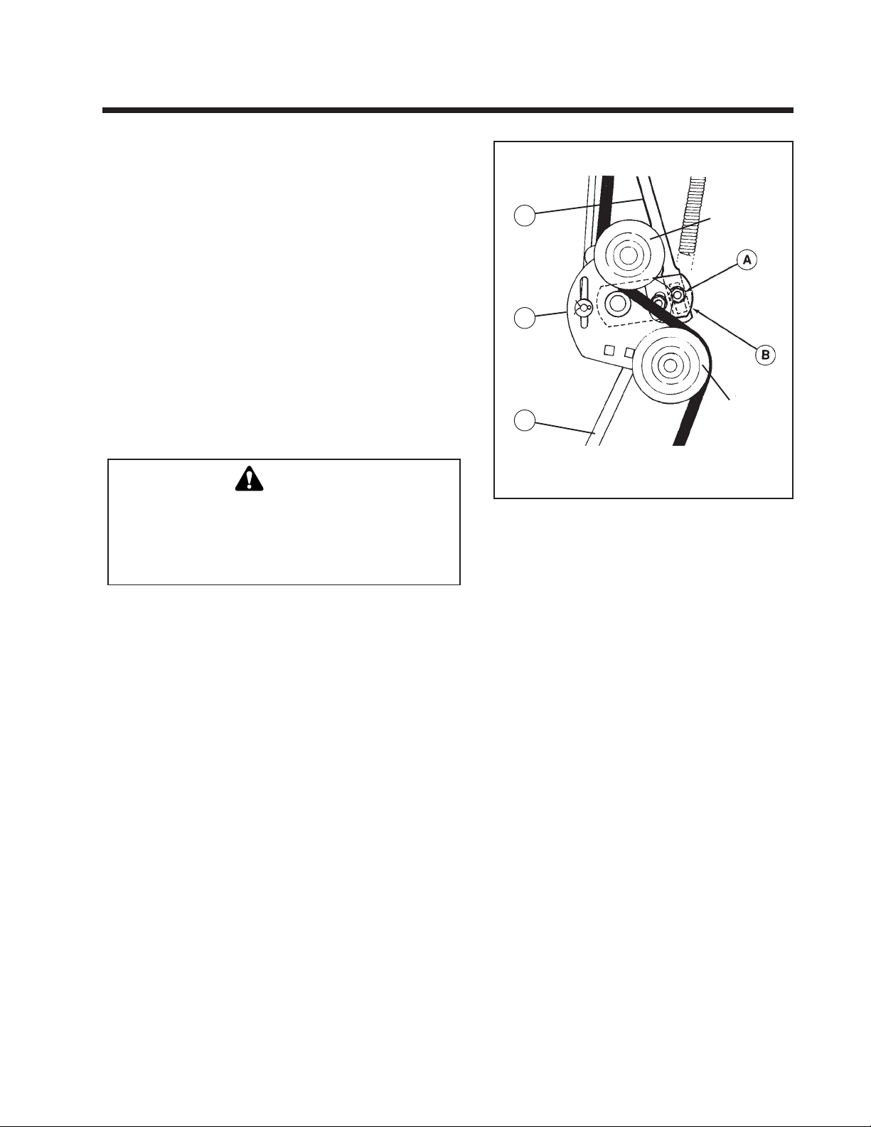
Figure 4-3 Neutral Adjustment
A. Nut
B. Idler Pivot Assembly
C. Rear Shift Rod
D. Idler Arm Assembly
E. Front Shift Rod
V-Pulley
Flat Idler
Pulley
4. Loosen nut (A, Figure 4-3) securingthe front shift rod (E) to
the idler pivot assembly (B) and rear shift rod lever (C).
The front shift rod must be free to move without disturbing the position of the rear shift rod (C).
5. Move the shift lever so that it is positioned in the neutral
gate.
6. Tighten nut (A) securely.
7. Check operation of unit for any movement with shift lever
in neutral gate. Perform the return-to -neutral adjustment
(refer to next page).
15
Page 20
Section 4. (Continued)
Tractors with HydroGear 216-3010L Hydrostatic Transaxle
Return-to-Neutral Adjustment - Hydro
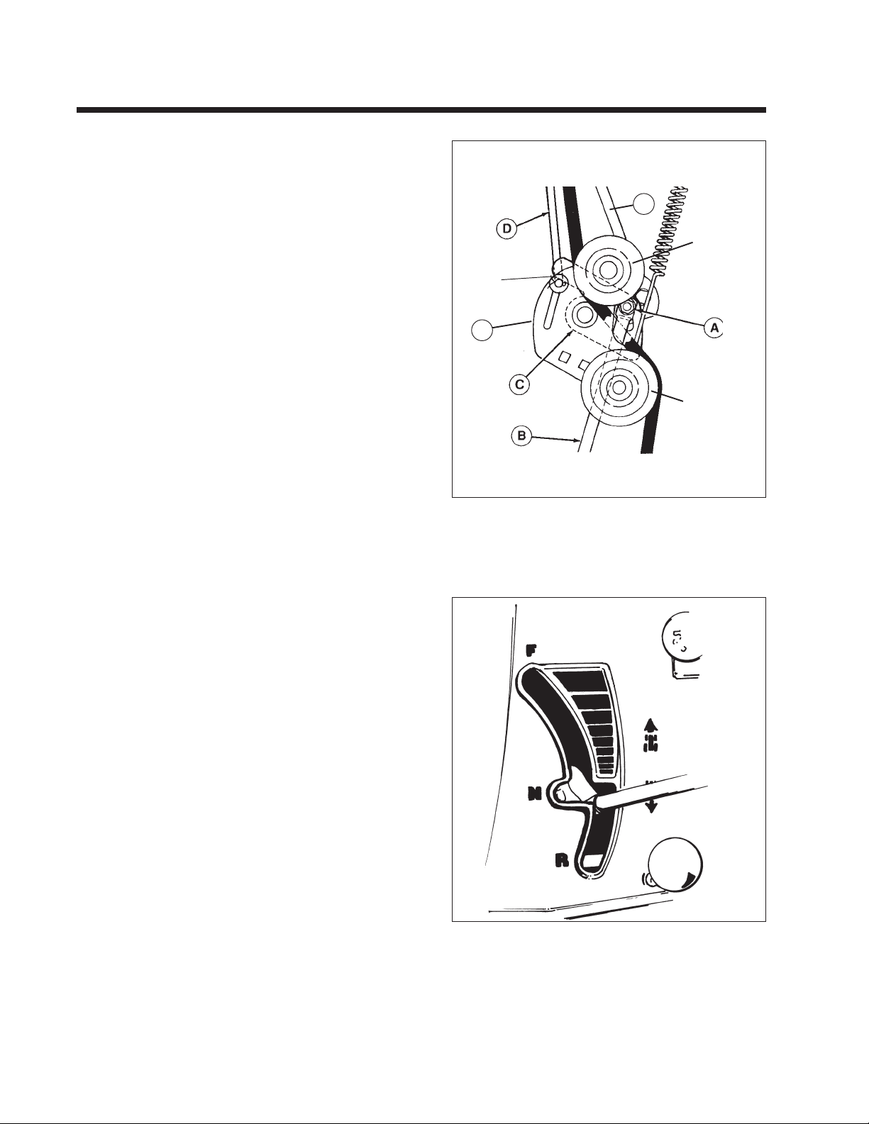
See figure 4-4. Perform the following adjustment if the shift
lever does not return to the neutral gate from a forward gear
position when the clutch/brake pedal is fully depressed.
1. Make sure the Neutral Adjustment is correct (refer to
preceding page).
2. Loosen the nut (A) that secures the rear shift rod (B) to the
return-to-neutral cam (C).
3. Hold the clutch/brake pedal fully down against the right
footrest. (Pedal can be clamped in this position with large
C-clamp if required.) Do not apply parking brake to hold
pedal, as pedal will not be held fully against footrest
without free play.
FRONT
➜
E
V-Pulley
Contact
Point
E
Flat Idler
Pulley
Viewed From Bottom Looking Up
Figure 4-4. Return-to-Neutral Adjustment
A. Nut D. Front Clutch Rod
B. Rear Shift Rod E. Front Shift Rod
C. Return-to-Neutral Cam F. Idler Arm Assy
4. See Figure 4-5. Position shift lever just below neutral gate shift lever shaft should be centered on corner at start of
reverse slot.
5. Rotate the return-to-neutral cam (C) securely against the
front clutch rod (D). There should be no gap between the
clutch rod and cam at the contact point.
6. Tighten nut (A) with pedal still held down against the
footrest.
7. Remove clamp from pedal. Start tractor and check return
to neutral operation. With pedal released, a small amount
of travel in the shift lever may be required to fully stop
tractor.
Figure 4-5. Proper Shift Lever Position For Return-to-Neutral
Position
16
Page 21
Section 5.
Tractors with Eaton 850 Transaxle
Neutral Adjustment
NOTE
The tractor may creep a small amount forward or
back-ward while in neutral gate when the parking
brake is not locked. Move control lever slightly
forward or back in the neutral gate to eliminate
creeping. If neutral is not found in neutral gate,
perform the following adjustment.
1. Raise the rear end of tractor off the ground.
Support tractor with heavy-duty jackstands
underneath the transaxle.
2. Securely block the front wheels to prevent any
forward or reverse tractor movement.
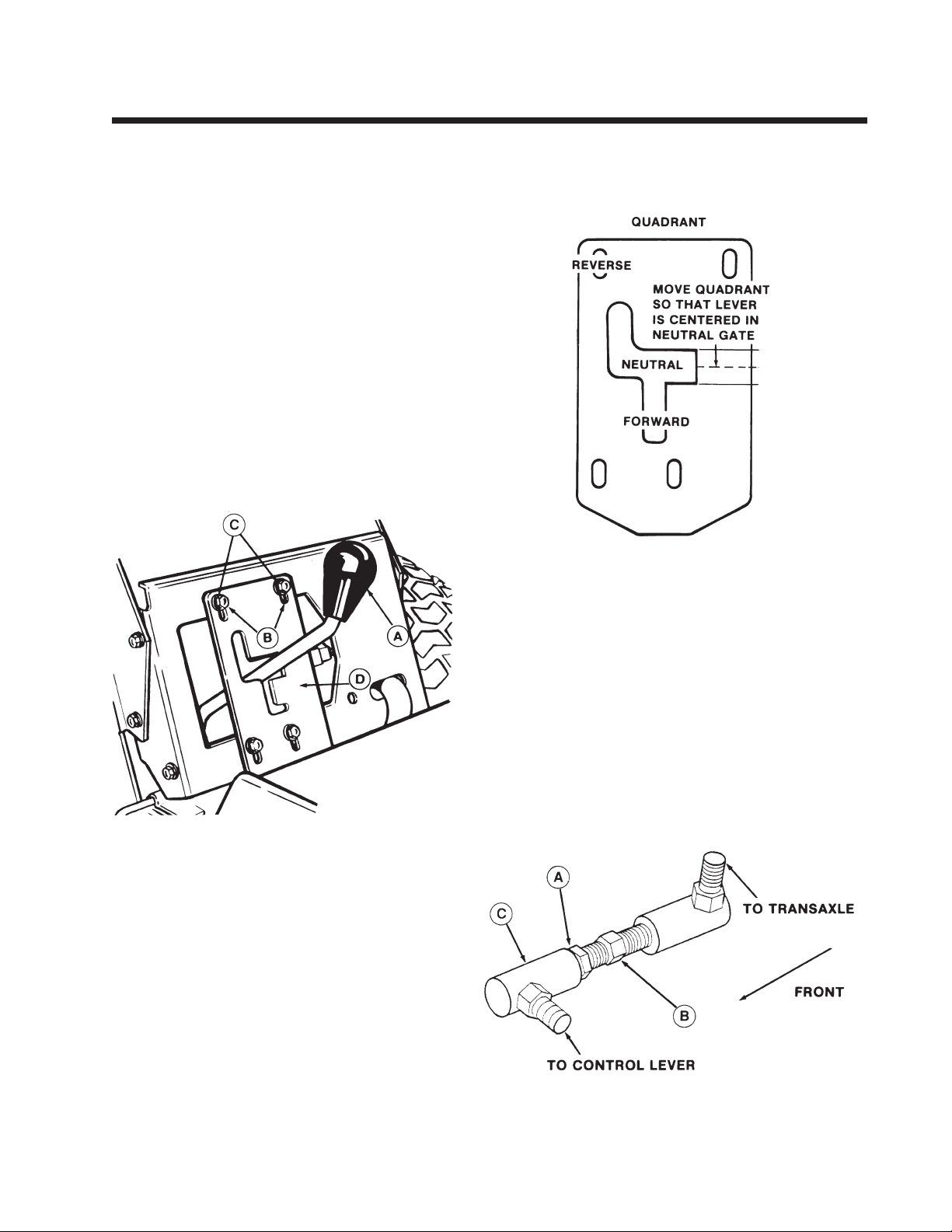
3. Open the seat deck. Unscrew knob and remove
front access panel by lifting over ground speed
control lever (A, figure 5-1).
4. Loosen, but do not remove, four capscrews (B) and
washers (C) securing quadrant (D). Make sure that
quadrant is free to move up and down.
Figure 5-1.
A. Speed Control
Lever
B. Capscrews
C. Washers
D. Quadrant
8. Stroke control lever to full forward position and return
lever to neutral. Center the lever in the neutral gate. Tires
will be rotating forward or backward.
Figure 5-2.
9. Loosen the jam nut (A, figure 5-3) on the speed control
linkage. Make sure control lever is still centered in neutral
gate.
10.While holding front ball joint (C), turn hex face on adjuster
shaft (B) until tires do not rotate.
11.Hold adjuster shaft (B) in place and tighten jam nut (A) up
by hand.
12.Hold ball joint still and tighten jam nut (A). Adjuster shaft
must not turn when tightening jam nut.
13.Recheck control lever in neutral gate. If lever is not centered,
loosen capscrews and adjust quadrant up or down to center
lever in neutral gate. Retighten capscrews.
14.Turn tractor off. Replace front access panel, replace knob,
and close seat deck. Remove jackstands.
5. Start the tractor and move throttle halfway to full
speed. Move the control lever up or down to find
exact neutral (tires do not rotate).
6. Adjust the quadrant so that the control lever is
centered from top to bottom in neutral gate. Refer
figure 5-2. Tighten capscrews if adjustment is
correct.
NOTE:
Only if control lever cannot be centered in neutral
gate, adjustment must be made to the speed control
linkage under-neath tractor (steps 7-13). Otherwise
continue to step 14.
7.
Move quadrant (D, figure 5-1) so that top of
capscrew (B) slots align with top of washers (C).
Tighten four capscrews.
Figure 5-3.
A. Jamnut
B. Adjuster Shaft
C. Front Ball Joint
17
Page 22
Section 6.
Tractors with Tuff Torq K60 Hydrostatic Transaxle
Neutral Adjustment
Note: Perform this adjustment procedure only if tractor
moves forward or reverse when ground speed control
lever is in neutral gate.
1. Place jackstand under each side of rear drawbar.
Adjust jackstand height until rear wheels are off the
ground.
2. Hydro transmission has pre-set internal neutral
adjustment. If tractor creeps when control lever is in
neutral, first loosen nut (A, figure 6-1) securing shift
rod lever (B) to shift pivot assembly (C). Directional
cam (E) will return to factory pre-set neutral. If wheels
continue to move with control lever in neutral, a
problem exists with internal adjustment. Contact the
Service Department. If wheels do not move, perform
the following steps to align cams.
3. Loosen nut (D) securing lever assembly pivot.
4. With nut (A) loosened, make sure ground speed
control lever is in neutral slot on dash.
5. Push spring-loaded directional cam (E) side-to-side
and allow cam to return-to-neutral.
6. With cam (E) stationary, move shift pivot assembly
(C) until 1/4" hole in cam and pivot assembly line up.
Insert 1/4" positioning pin (F) or 1/4" rod thru both
parts. Cam (E) must remain in neutral position.
7. With positioning pin in place, tighten nut (D) and
then tighten nut (A).
8. Remove positioning pin and move ground speed
control lever through forward and reverse ranges and
return lever to neutral.
9. Check to see if positioning pin can be freely inserted
(from bottom side) through directional cam (E) and
lever assembly (C). If alignment if good, go to step 10.
If pin cannot be inserted, repeat steps 2-8.
10. With ground speed control lever in neutral position,
start tractor (with rear wheels off the ground) and
check for wheel movement. Wheels should not move
due to internal neutral adjustment. If wheels move,
recheck that positioning pin can be inserted freely
through directional cam (E) and lever assembly (C)
with ground speed control lever in neutral position.
If neutral cannot be found, a problem exists with the
tractor shift linkages.
11. After neutral adjustment, move the ground speed
control lever to forward range and depress clutch/
brake pedal. The control lever should return to the
neutral position in dash and wheels should not move.
Move ground speed control lever to reverse range and
repeat check.
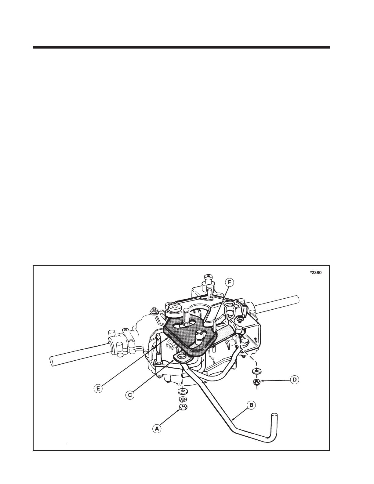
Figure 6-1. Neutral Adjustment
A. Nut, 1/4
B. Shift Rod Lever
C. Shift Pivot Assembly
D. Nut, 5/16
E. Cam
F. Positioning Pin
18
Page 23
Section 6. (Continued)
Tractors with HydroGear 311-0750/311-0800 Transaxle
Neutral Adjustment
Perform the following adjustment if the shift lever
must be moved out of the neutral gate to prevent
forward or reverse tractor movement. With the
clutch/brake pedal released, a small amount of
travel in the shift lever may be required to fully
stop tractor.
1. Position rider on flat level ground. Make sure the
ground speed control lever is securely in the
neutral gate.
2. Raise the rear of tractor off ground and support
securely with jackstands.
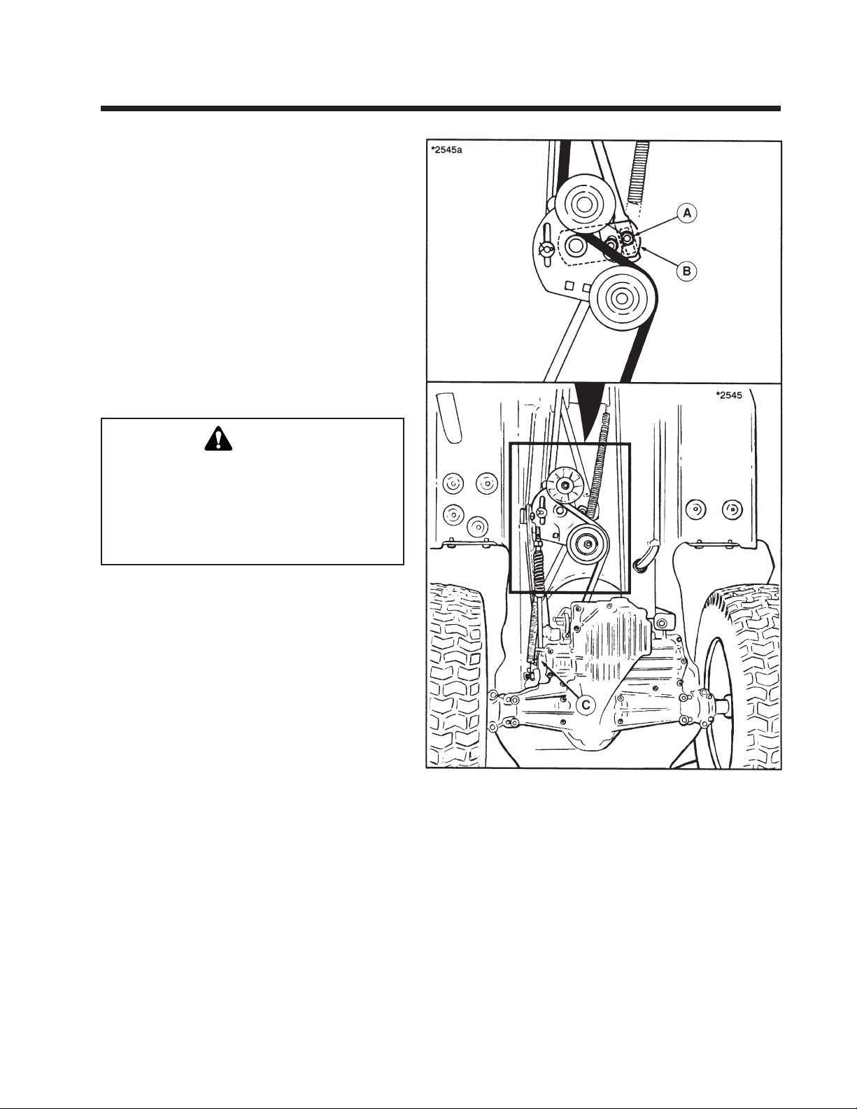
3. Loosen nut (A, figure 6-2) securing the front shift
rod to the idler pivot assembly (B). The carriage
bolt must be free to move in the shift rod slot.
WARNING
When making adjustment, keep hands, hair,
clothing, or tools away from rotating belts. Grasp
cam lever at base to keep hand several inches
below belt rotating around idler pulley assembly. Careless or improper attention may result in
serious injury.
4. Start the tractor and rotate the hydro cam lever
(C) until rear wheels stop moving. Shut off
tractor engine.
5. Tighten nut (A) securely.
6. Check operation of tractor for any movement
with shift lever in neutral gate. Perform the
return-to-neutral adjustment (refer to following
paragraph).
Figure 6-2. Neutral Adjustment
A. Nut C. Hydro Cam Lever
B. Idler Pivot Assembly
19
Page 24
Section 6. (Continued)
Tractors with HydroGear 311-0750/311-0800 Transaxle
Return-to-Neutral Adjustment
Perform the following adjustment if the shift lever
does not return to the neutral gate when the clutch/
brake pedal is fully depressed.
1. Make sure the Neutral Adjustment is correct
(refer to preceding paragraph).
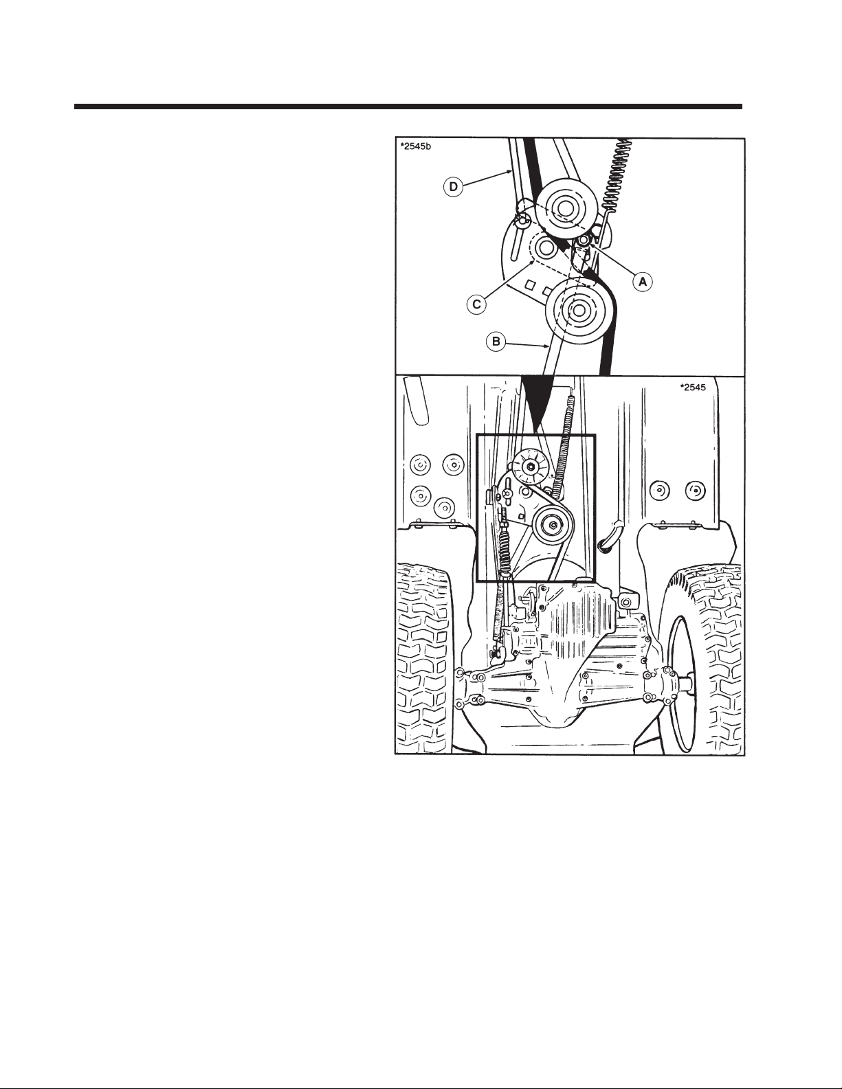
2. Loosen the nut (A, figure 6-3) that secures the
rear shift rod (B) to the return-to-neutral cam (C).
3. Hold the clutch/brake pedal fully down against
the right footrest. Pedal can be clamped in this
position with large C-clamp if required. Do not
apply parking brake as pedal will not be held
against footrest without free play.
4. Rotate the return-to-neutral cam (C) securely
against the front clutch rod (D). There should be
no gap between the clutch rod and cam.
5. Tighten nut (A) with pedal held down against
footrest.
6. Start tractor and check return-to-neutral operation. With pedal released, a small amount of
travel in the shift lever may be required to fully
stop tractor.
Figure 6-3. Return-to-Neutral Adjustment
A. Nut C. Return-to-Neutral Cam
B. Rear Shift Rod D. Front Clutch Rod
20
Page 25
Section 6. (Continued)
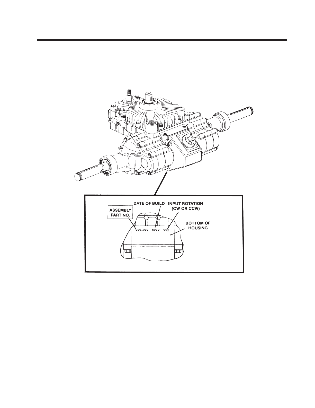
Lawn Tractors with Eaton 750 or 751 Transaxles
Locate Assembly Number (750 or 751) and refer to the
following three pages before adjusting.
Early Model 750 with Welded Support Bracket ............... 21
Later Model 750 with Plastic Support Bracket ................. 22
Model 751 ................................................................................ 23
21
Page 26
Section 6. (Continued)
Lawn Tractors with Eaton 750 Hydrostatic Transaxle
Check Preceding Page to
Locate Assembly Number.
NOTE: Perform the Clutch/Brake Adjustment before
doing the Neutral Adjustment.
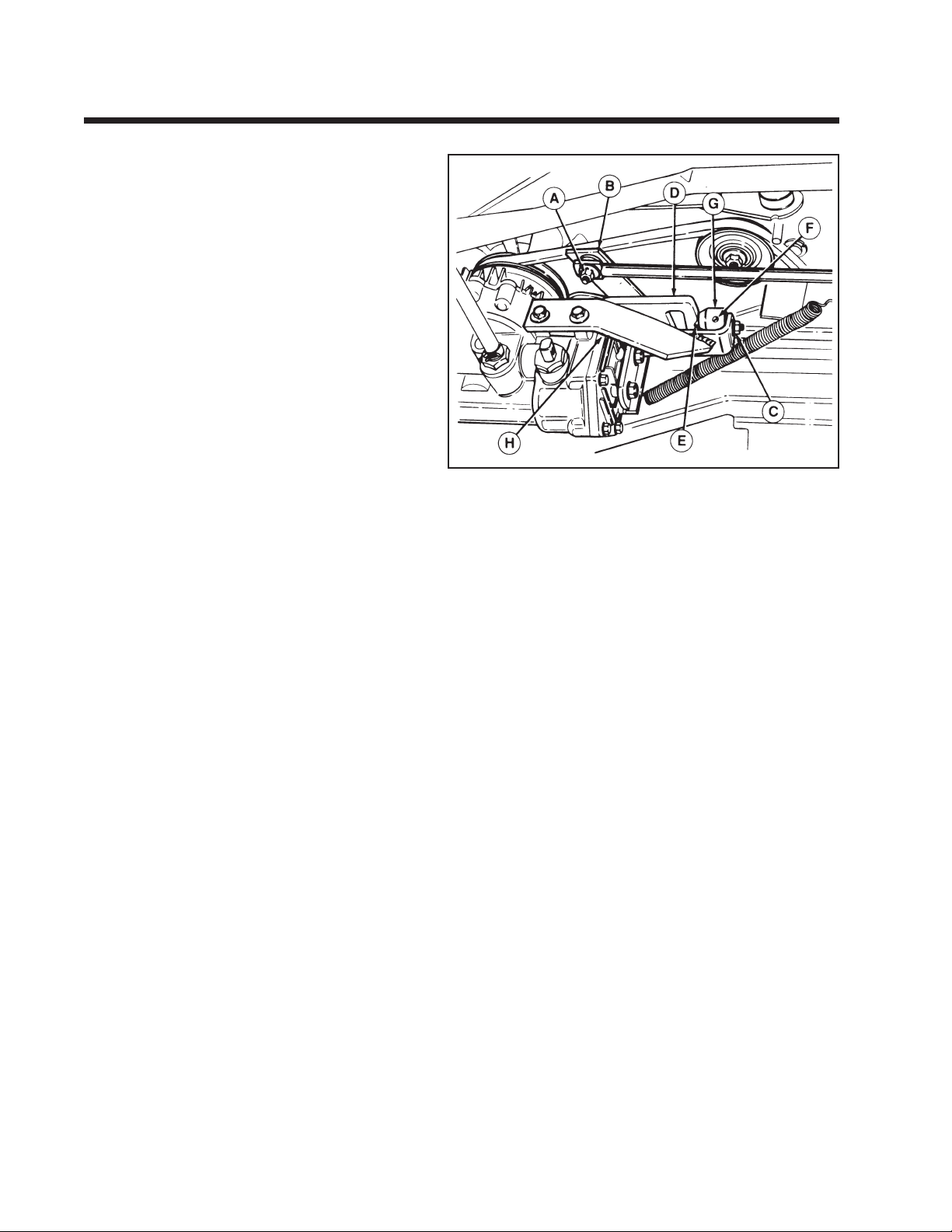
Neutral Adjustment
Early Models with Welded Support Bracket
(H, Figure 6-4)
1. Park tractor on level surface. Shut off PTO switch
and engine. Do not apply parking brake. Make
sure transmission control lever is in neutral and
has activated neutral switch light (ignition switch
on)
2. Raise rear of tractor off ground with a suitable
hoist or floor jack. Install jackstands underneath
transaxle and block front wheels.
3. Loosen nut (A, figure 6-4) securing transaxle shift
rod to speed control lever (B).
4. Loosen nut (C) securing ball retainer (G) to
welded support bracket (H).
5. Rotate shift cam (D) so that neutral detent is
aligned with roller ball (E).
6. Start engine and increase to full throttle. If wheels
rotate, continue with adjustment. If wheels do not
rotate go to step 8.
7. Place a 1/4" rod or #2 Phillips screwdriver into
hole (F) in eccentric ball retainer (G). Rotate ball
retainer until wheels stop moving.
8. Tighten nut (C) securing ball retainer (G).
9. Make sure dash transmission control lever is in
neutral position and has activated neutral switch
light (ignition switch) before tightening nut (A).
10. Check the "Return-To-Neutral" by following these
steps:
a. Shift transmission lever into forward (drive)
position and fully depress clutch/brake pedal.
b. Lever should return to neutral slot.
c. If lever does not return to neutral, repeat above
steps 1-9.
11. Shut off engine and remove tractor from
jackstands.
Figure 6-4.
A. Nut
B. Speed Control Lever
C. Nut
D. Shift Cam
E. Roller Ball
F. Adjustment Hole
G. Eccentric Ball Retainer
H. Support Bracket (Welded)
For later models with plastic bracket see page 22.
22
Page 27
Section 6. (Continued)
Lawn Tractors with Eaton 750 Hydrostatic Transaxle
Neutral Adjustment
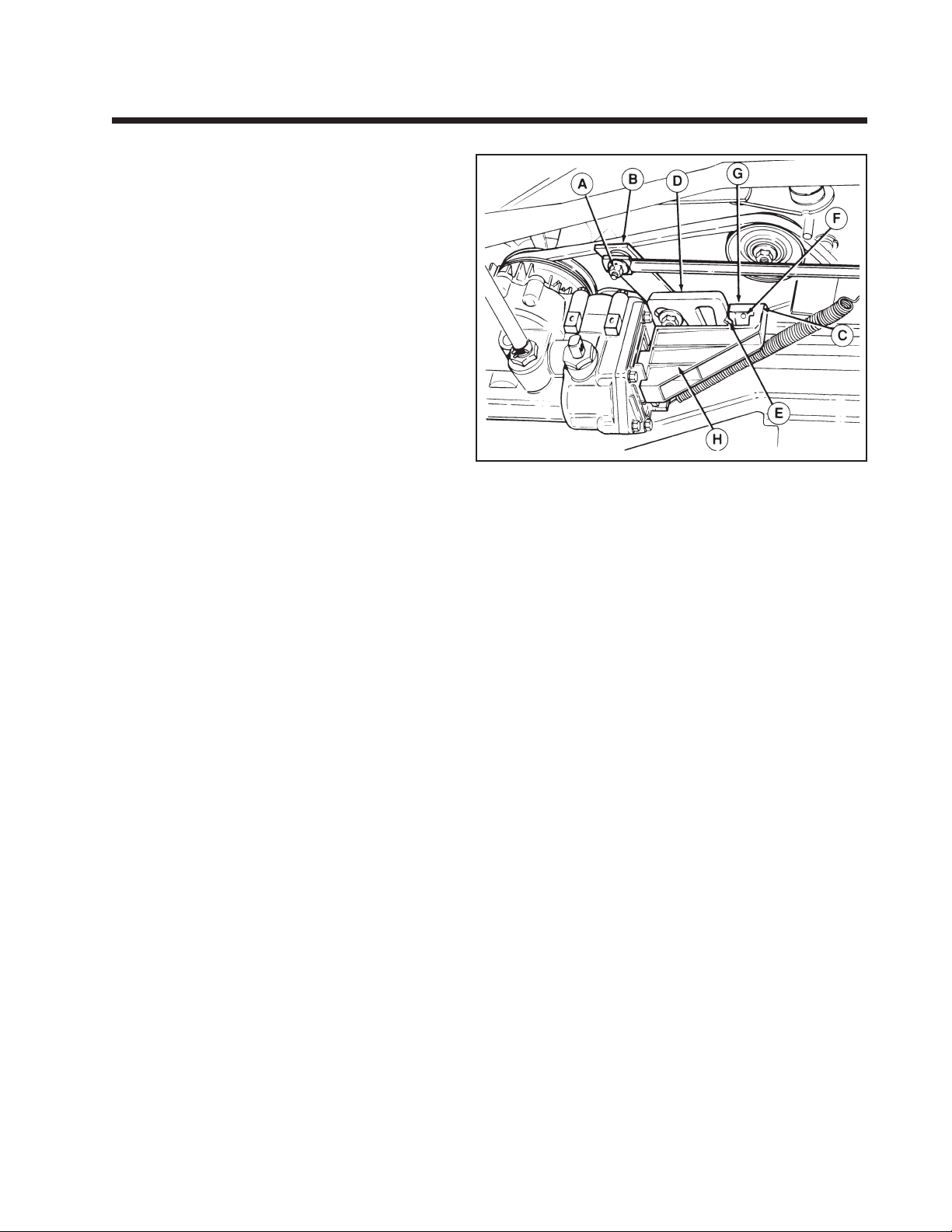
Later Models with Plastic Bracket (H, Figure 6-5)
1. Park tractor on level surface. Shut off PTO switch
and engine. Do not apply parking brake. Make
sure transmission control lever is in neutral and
has activated neutral switch light (ignition switch
on).
2. Raise rear of tractor off ground with a suitable
hoist or floor jack. Install jackstands underneath
transaxle and block front wheels.
3. Loosen nuts (A, figure 6-5) on both left side and
right side of speed control lever (B). (Left side nut
is located next to spring and not shown in
illustration.)
4. Loosen nut (C) securing ball retainer (G) to
plastic support bracket (H).
5. Rotate shift cam (D) so that neutral detent is
aligned with roller ball (E).
6. Start engine and increase to full throttle. If wheels
rotate, continue with adjustment. If wheels do not
rotate, go to step 8.
7. Place a 1/4- rod or #2 Phillips screwdriver into
hole (F) in eccentric ball retainer (G). Rotate ball
retainer until wheels stop moving.
8. Tighten nut (C) securing ball retainer (G).
9. Shut off engine and make sure dash transmission
control lever is in neutral position, and has
activated neutral light (Ignition switch on).
10. Pull right end of speed control lever (B) fully
forward. Tighten the left side 1/4" nut (not
shown).
11. Push the right end of speed control lever (B) fully
rearward and tighten right side 5/16" nut (A).
12. Check the "Return-To-Neutral" by following these
steps:
a. Shift transmission lever into forward (drive)
position and fully depress clutch/brake pedal.
b. Lever should return to neutral slot.
c. If lever does not return to neutral, repeat above
steps 1-11.
13. Remove tractor from jackstands.
Figure 6-5.
A. Nut
B. Speed Control Lever
C. Nut
D. Shift Cam
E. Roller Ball
F. Adjustment Hole
G. Eccentric Ball Retainer
H. Support Bracket (Plastic)
For early models with welded support bracket see page 21.
23
Page 28
Section 6. (Continued)
Lawn Tractors with Eaton 751 Hydrostatic Transaxle
Neutral Adjustment
1. Park tractor on level surface. Shut off PTO switch and
engine and remove key. Do not apply parking brake.
Make sure transmission control lever is in neutral.
2. Raise rear of tractor off ground with a suitable hoist
or floor jack. Install jackstands underneath transaxle
and block front wheels.
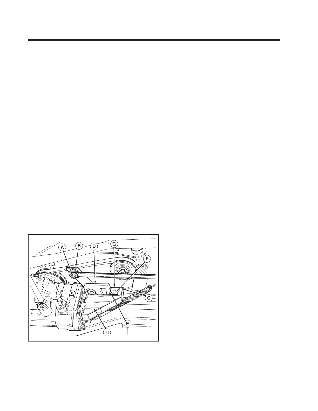
3. Loosen nuts (A, figure 6-6) on both left side and right
side of speed control lever (B). (Left side nut is located
next to spring and not shown in illustration.)
4. Rotate shift cam (D) so that neutral detent is aligned
with roller ball (E).
5. Start engine and increase to full throttle. If wheels
rotate, continue with adjustment. If wheels do not
rotate, go to step 9.
6. Loosen nut (C) securing ball retainer (G) to plastic
support bracket (H).
7. Place a 1/4" rod or #2 Phillips screwdriver into hole
(F) in eccentric ball retainer (G). Rotate ball retainer
downward (from RH side) until wheels rotate
forward. Rotate ball retainer slowly upward from RH
side) until wheels stop moving. (Neutral must be
obtained coming from forward.)
8. Tighten nut (C) securing ball retainer (G).
9. Shut off engine and make sure dash transmission
control lever is in neutral position against rear edge of
neutral slot in dash.
10. Pull right end of speed control lever (B) fully forward.
Tighten the left side 1/4" nut (not shown).
11. Push the right end of speed control lever (B) fully
rearward and tighten right side 5/16" nut (A).
12. Start the engine and run at full throttle. Check for
neutral by moving control lever into forward and
reverse and back into neutral gate. Control lever can
be moved a small amount forward or backward in
neutral gate to avoid tractor movement. Continue
with adjustment if neutral cannot be obtained.
13. Shut off engine. Loosen 1/4" nut at LH end of speed
control lever. Pull speed control lever toward right
with transmission control lever against rear edge of
neutral slot in dash. Retighten 1/4" nut.
14. Repeat step 12.
15. Shut off engine. Loosen 1/4" nut at LH end of speed
control lever. Position transmission control lever out
of neutral slot toward reverse to the point where
notched
out portion of lever is even with rear edge of neutral
slot. Pull speed control lever toward right.
Retighten 1/4" nut.
16. Repeat step 12.
17. Return-To-Neutral Adjustment is correct when the
above adjustment steps are followed.
18. Remove the tractor from jackstands.
Figure 6-6. Neutral Adjustment
A. Nut
B. Speed Control Lever
C. Nut
D. Shift Cam
E. Roller Ball
F. Adjustment Hole
G. Eccentric Ball Retainer
H. Support Bracket
24
Page 29
Section 7.
Lawn Tractors with HydroGear (Formerly Agri-Fab) Sundstrand BDU10S Transaxle
Neutral Adjustment - (Linkage with two ball joints)
If the tractor creeps forward or back with transmission in
neutral notch, adjust as follows.
1. Seat yourself in the operator’s seat and start the
engine.
2. Move the lever to position where tractor remains
stationary. This is neutral position.
3. Stop the engine.
4. Disconnect the battery cables to avoid causing short
circuit or sparks with tools.
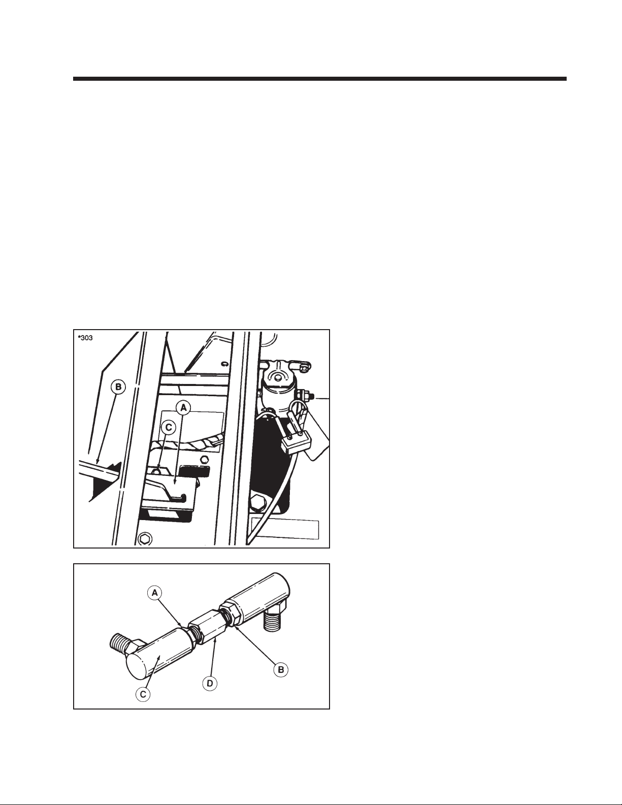
5. The control lever quadrant (A, figure 7-1) is mounted
with slotted holes so it can be adjusted. Loosen the
two self-tapping screws (C) and move the quadrant so
the lever is centered in the quadrant gate. Then
tighten the two screws.
6. Connect the battery cables.
7. Lower the seat deck. Start the engine to check again. If
the tractor still creeps in neutral, proceed to step 8.
8. Return the quadrant to the center position, if moved.
Loosen the front nut (A, figure 7-2) and rear nut (B)
on the hydro shift rod (C). The rear nut is a left-hand
thread.
9. Using an open-end wrench, turn the hex shaft (D)
three turns upwards (toward the frame) if the tractor
Is creeping forward, or downward (toward the
ground) if the tractor is creeping backwards.
10. Hold hex shaft and tighten front and rear nuts (A & B,
figure 7-2).
11. Repeat steps 1 through 7 to read just the hydro lever
in the neutral gate.
12. Repeat entire procedure until tractor does not creep
with hydro lever in neutral gate.
*2223
Figure 7-1. Control Lever Quadrant
A. Quadrant
B. Transmission Engagement Lever
C. Taptite Screw
Figure 7-2.
A. Front Jam Nut
B. Rear Jam Nut
C. Hydro Shift Rod
D. Hex Shaft
25
Page 30
Section 7. (Continued)
Lawn Tractors with HydroGear (Formerly Agri-Fab) Sundstrand BDU10S Transaxle
Neutral Adjustment - (Linkage with one ball joint)
If the tractor creeps forward or back with transmission in
neutral notch, adjust as follows:
1. Raise rear of tractor off ground with suitable hoist or
floor jack. Install jackstands underneath transaxle and
block front wheels.
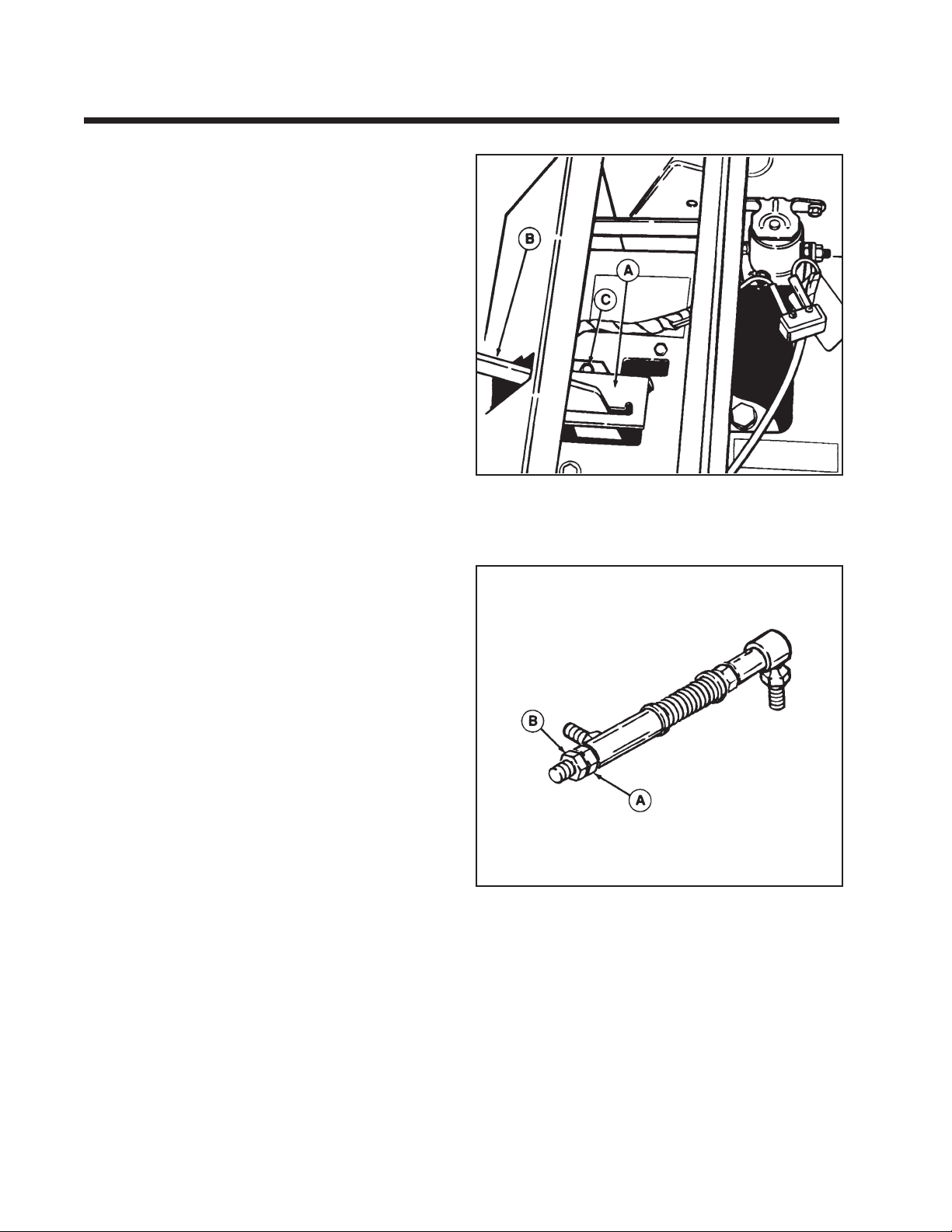
2. Raise the seat deck. The control lever quadrant (A.
Figure 7-3. ) is mounted with slotted holes so it can be
adjusted. Loosen the two self-tapping screws (C) and
move the quadrant so the screws are centered in the
quadrant slots. Then tighten the two screws.
3. Place speed control lever in neutral position. Start
engine and run at maximum RPM.
4. Loosen jam nut (B, figure 7-4) and adjust control link
length by rotating nut (A, figure 7-4) in either direction until wheels stop rotating. Snug jam nut (B)
finger-tight.
5. Check for neutral from forward and reverse with
speed control lever. Repeat steps 3 and 4 if needed.
6. Hold the adjustment nut (A) and tighten outer jam
nut (B) securely.
7. Remove unit from jackstands or jack.
*303
Figure 7-3. Control Lever Quadrant
A. Quadrant
B. Transmission Engagement Lever
C. Taptite Screw
*2231
Figure 7-4. Hydro Control Linkage
A. Adjustment Nut
B. Jam Nut
26
Page 31
Section 7. (Continued)
Lawn Tractors with HydroGear 310 - 0500 Transaxle (With Hand Control)
*2538
WARNING
To avoid serious injury, perform adjustments
only with engine stopped, key removed and tractor on level ground.
Neutral Adjustment
If the tractor creeps forward or backward with
ground control speed lever positioned in the neutral
gate, perform the following adjustment.
1. Raise rear of tractor off ground with suitable
hoist or floor jack. Install jackstands underneath
transaxle and block the front wheels.
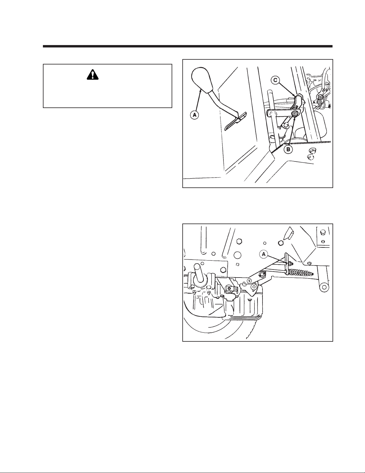
2. See figure 7-5. Place speed control lever (A) in the
NEUTRAL gate. Start the engine and run at
maximum RPM.
3. Raise the seat deck. Loosen nut (B) and adjust
linkage rod (C) up or down until wheels stop
rotating, then tighten nut (B) securely.
4. Turn off the engine and remove tractor from jack
stands or jack.
Figure 7-5. Neutral Adjustment
A. Ground Speed Control Lever
B. Nut
C. Linkage Rod
*2537
Return-to-Neutral Adjustment
1. See figure 7-6. Depress clutch/brake pedal fully.
Ground speed control lever should return to the
neutral gate.
2. Turn nut (A, figure 7-6) in either direction until
proper adjustment is achieved and control lever
returns fully to the neutral gate.
Note: Return to neutral functions from any forward
setting only.
Figure 7-6. Return-to-Neutral Adjustment - (Viewed from Right
Side of Transaxle with the Rear Wheel Removed)
A. Nut
27
Page 32
Section 7. (Continued)
Lawn Tractors with HydroGear 318-0500/322-0500/322-0650 Transaxle (With Foot Control)
WARNING
When making adjustment, keep hands, hair,
clothing, and tools away from rotating belts.
Grasp cam lever at base to keep hand several
inches below belt rotating around idler pulley
assembly. Careless or improper attention may
result in serious injury.
If the tractor creeps forward or backward with the
engine running and both travel pedals released,
perform the following adjustment:
NOTE: For Hydro-Gear 0500 transmission part
number 1713761 see Figure 7-7. For the Hydro-Gear
0650 transmission part number 1715765 see Figure
7—8. An identification decal is attached to the
transmission case.
1. Block the front wheels and raise the rear of the
tractor off the ground with a suitable hoist or
floor jack. Install jackstands underneath the
transaxle.
2. Start the engine and release the parking brake
while keeping seat switch depressed.
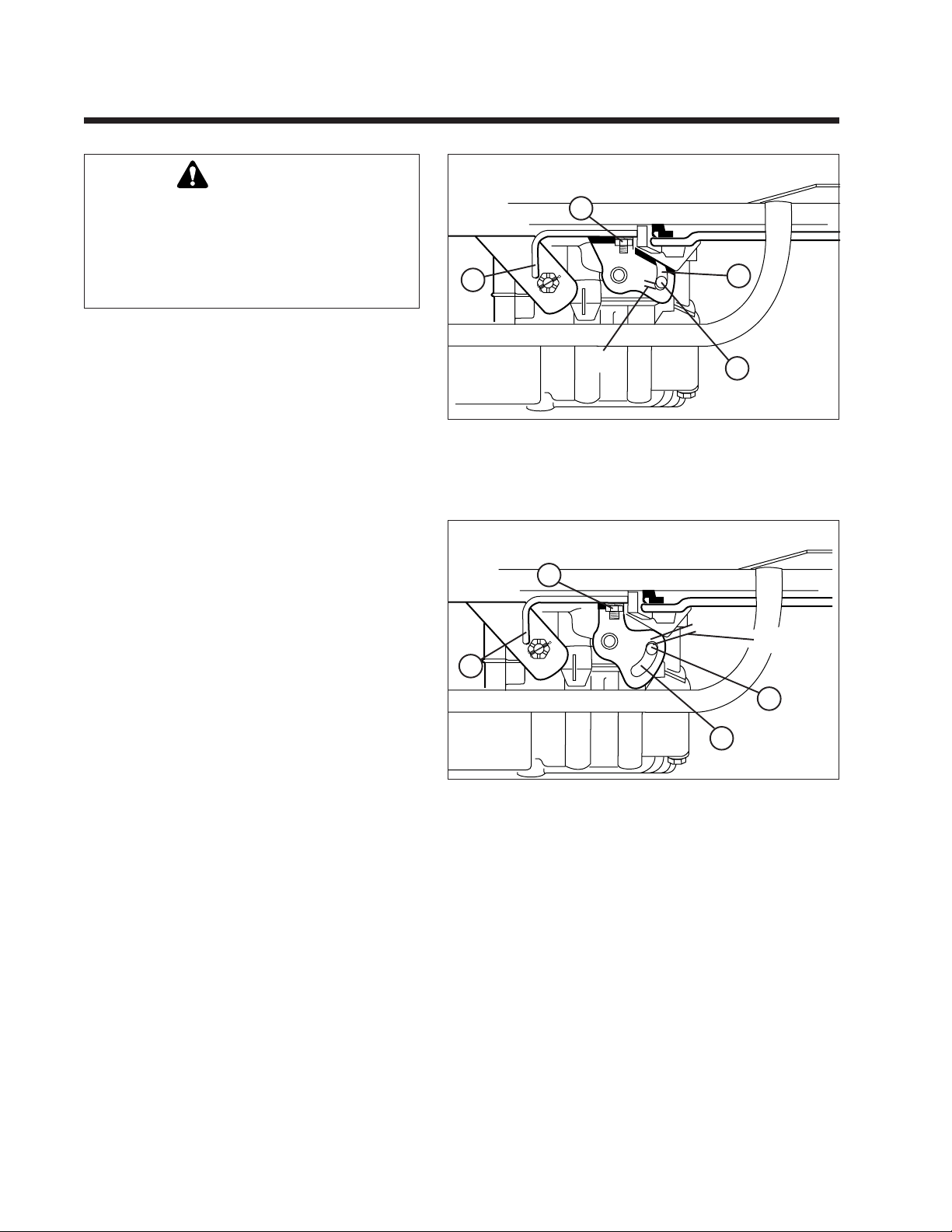
3. Loosen the nut (A) securing the neutral adjustment rod (B). Move the rod until neutral is found,
then retighten the nut.
NOTE: The stop pin (D, Figure 7-7 and 7-8) should
be positioned near the end of the cam slot when the
front pedal edge is 1/4" above the frame (pedal fully
depressed). If it is not, proceed to the Forward
Speed Adjustment procedure. The stop pin should
not “bottom out” in the cam slot. Increasing the
distance between the end of the cam slot and the
stop pin will increase reverse speed and decrease
forward speed.
Viewed from right side of tractor with rear
wheel removed and foot pedal fully depressed.
A
B
Gap
Figure 7-7 Neutral Adjustment - Hydro-Gear 0500, Part Number
1713761
A. Nut C. Cam Slot
B. Neutral Adjustment Rod D. Stop Pin
Viewed from right side of tractor with rear wheel removed and
foot pedal fully depressed.
C
D
A
Gap
B
D
C
Figure 7-8. Neutral Adjustment - Hydro-Gear 0650 Part Number
1715765.
(Linkage removed for clarity)
A. Nut C. Cam Slot
B. Neutral Adjustment Rod D. Stop Pin
28
Page 33
Section 7. (Continued)
Lawn Tractors with HydroGear 318-0500/322-0500/322-0650 Transaxle (With Foot Control)
If the unit does not reach top speed with the forward
direction pedal fully depressed, perform the following adjustment with the engine off and PTO disengaged.
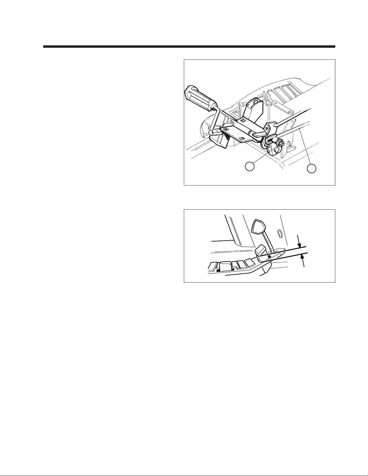
1. See Figure 7-9. Loosen the nut (A) securing the
control rod to the hydro control lever.
2. Position the pedal so the distance between the
frame and bottom edge of the pedal is 1-3/4" as
shown in Figure 7-10.
3. With pedal in this position, tighten the nut (A,
Figure 7-9).
4. The stop pin (D, Figure 7-7 and 7-8 previous
page) should be positioned at the end of the cam
slot as shown when the front pedal edge is 1/4"
above the frame (pedal fully depressed). If it is
not, loosen nut (A, Figure 7-9) and adjust pedal as
necessary, then retighten nut.
NOTE: The stop pin (D, Figure 7-7 and 7-8) should
be positioned near the end of the cam slot when the
front pedal edge is 1/4" above the frame (pedal fully
depressed). The stop pin should not “bottom out” in
the cam slot. Increasing the distance between the
end of the cam slot and the stop pin will increase
reverse speed and decrease forward speed.
Unit pictured from above with frame removed.
A
Figure 7-9 Forward Speed Adjustment Linkage - Hydro Models
A. Nut B. Control Rod
B
1 3/4"
Figure 7-10 Forward Speed Adjustment - Hydro
29
Page 34
Section 8.
Lawn Tractors with Eaton Model 7 Hydrostatic & Peerless 1300 Series Transaxle
Neutral Adjustment
If the tractor creeps forward or back with transmission in
neutral notch, adjust as follows.
1. Seat yourself in the operator’s seat and start the
engine.
2. Move the lever to position where tractor remains
stationary. This is neutral position.
3. Stop the engine.
4. Disconnect the battery cables to avoid causing short
circuit or sparks with tools.
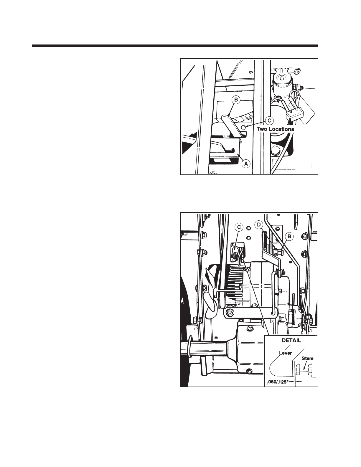
5. Raise the seatdeck. The control lever quadrant (figure
8-1) is mounted with slotted holes so it can be
adjusted. Loosen the two self-tapping screws and
move the quadrant so the lever moves to the correct
position. Then tighten the two screws.
4. Connect the battery cables.
5. Lower the seat deck. Start the engine to check again. If
the tractor still creeps in neutral, repeat the procedure
to adjust.
Transmission Control Lever
If lever operates too hard or loose, it can be adjusted.
Loosen or tighten the nut (B, figure 8-2) to loosen or
tighten the lever. Some models are equipped with
setscrews (D) which must be loosened to adjust the nut.
*303
Figure 8-1. Control Lever Quadrant
A. Quadrant
B. Transmission Engagement Lever
C. Capscrews
Transmission Engagement Lever
If transmission engagement lever (under seat) does not
work properly, check the adjustment as follows.
1. Release the parking brake.
2. Place the transmission control lever in NEUTRAL.
3. Place the transmission engagement lever (B, figure 8-
1) in forward position (disengage position).
4. Locate the plunger (A, figure 8-2) on front of the
transmission which is operated by the lever. Check
the clearance between the plunger and the fitting as
shown in the detail in figure 8-2. It should be 0.060
inch to 0.125 inch.
5. To adjust, loosen the screws (C, figure 8-1) which
secure the engagement lever support bracket (C,
figure 8-2) and move bracket to achieve the 0.060 to
0.125 inch dimension, then tighten the screws.
Figure 8-2. Engagement Lever
A. Plunger C. Support Bracket
B. Nut D. Setscrews
30
Page 35
Section 9.
Later Model Front-Cut Rider with Eaton Model 7 Hydrostatic
Neutral Adjustment
WARNING
Keep away from moving parts when engine is
running.
1. Adjustment can be performed with mower
installed.
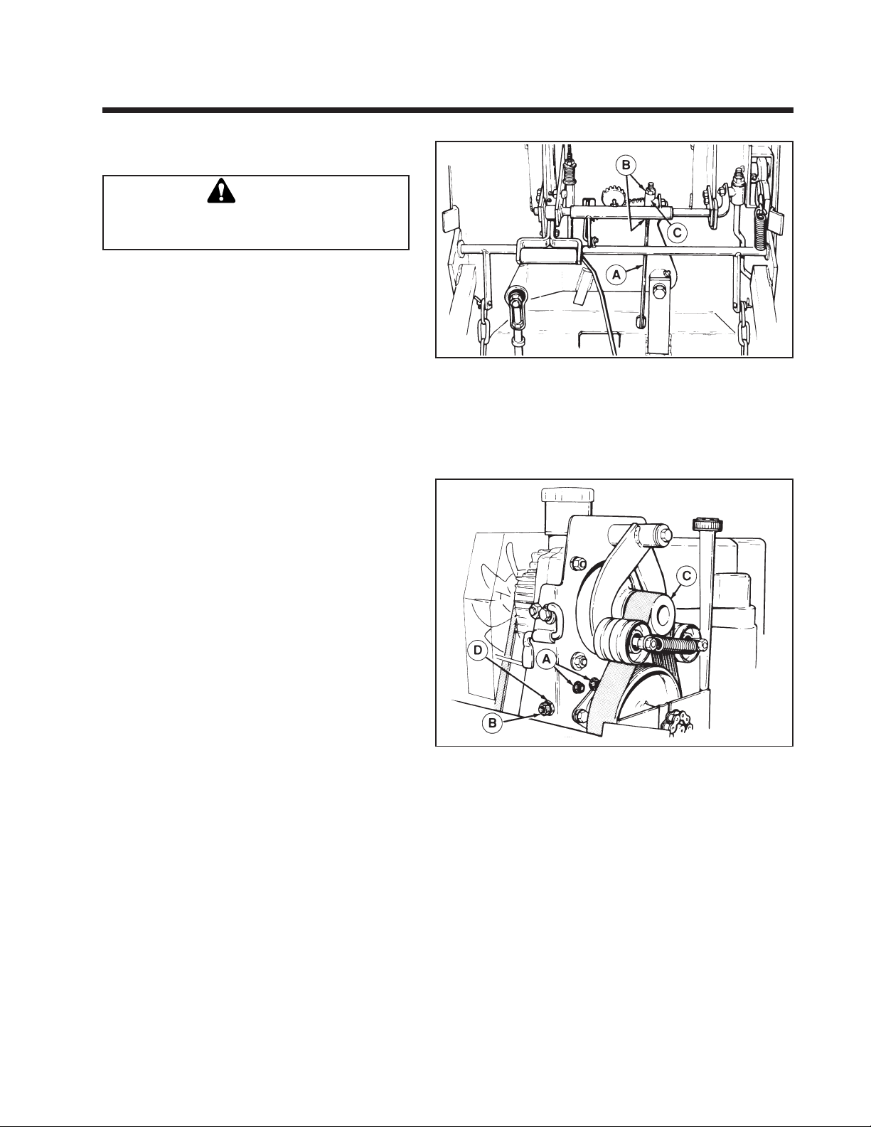
2. Loosen nuts (B, figure 9-1) on either side of guide
(C). Leave 1/4" clearance on each side.
3. Loosen the two capscrews (A. figure 9-2).
4. Raise front tires off the ground by placing jack
stands under each side of frame. Do not support
rider at axle as axle will rotate during adjustment.
5. Start the engine and raise the seat deck. For an
accurate neutral adjustment, keep engine RPM
level high during adjustment.
6. Loosen the jam nut (B). Turn the inner nut (D)
either left or right until the output pulley (C)
stops turning.
7. Tighten the two capscrews (A).
8. Tighten the jam nut (B) against inner nut (D).
9. Shut off the engine.
10. Make sure transmission control lever is in
neutral.
11. Tighten the two nuts (B, figure 9-1) against the
guide. Make sure rod guide does not move when
tightening nuts.
12. The rider can be taken off the jackstands.
*1948
Figure 9-1. Hydro Control Rod
A. Hydro Control Rod
B. Nuts
C. Guide
Figure 9-2. Neutral Adjustment
A. Capscrews
B. Jam Nut
C. Pulley
D. Adjustment Nut
31
Page 36
Section 10.
Early Model Front-Cut Rider with Eaton Model 7 Hydrostatic
Neutral Adjustment
WARNING
Keep away from moving parts when engine is
running.
1. Remove the mower from the rider.
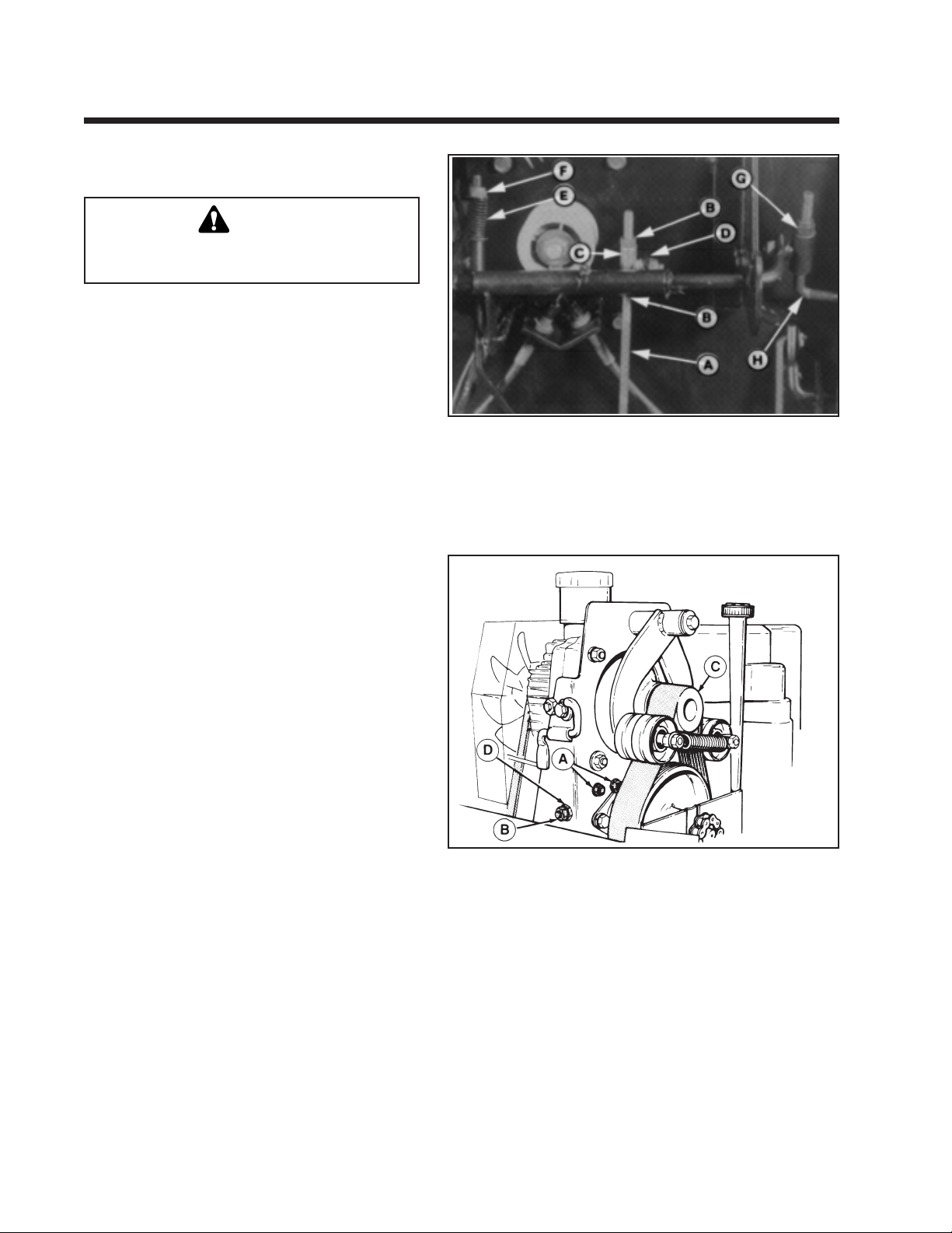
2. Loosen nuts (B, figure 10-1) on either side of
guide (C). Leave 1/4" clearance on each side.
Figure 10-1. Hydro Control Rod
A. Hydro Control Rod E. Spring, Clutch
B. Nuts F. Nut, Clutch Rod
C. Guide G. Nut, Brake Rod
D. Bracket H. Brake Rod
3. Loosen the two capscrews (A, figure 10-2).
4. Raise front tires off the ground by placing
jackstands under each side of frame.
5. Start the engine and raise the seat deck. For an
accurate neutral adjustment, keep engine RPM
level high during adjustment.
6. Loosen the jam nut (B). Turn the inner nut (D)
either left or right until the output pulley (C)
stops turning.
7. Tighten the two capscrews (A).
8. Tighten the jam nut (B) against inner nut (D).
9. Shut off the engine.
10. Make sure transmission control lever is in
neutral.
11. Tighten the two nuts (B, figure 10-1) against the
guide.
12. The rider can be taken off the jackstands.
*1945
Figure 10-2. Neutral Adjustment
A. Capscrews
B. Jam Nut
C. Pulley
D. Adjustment Nut
32
Page 37
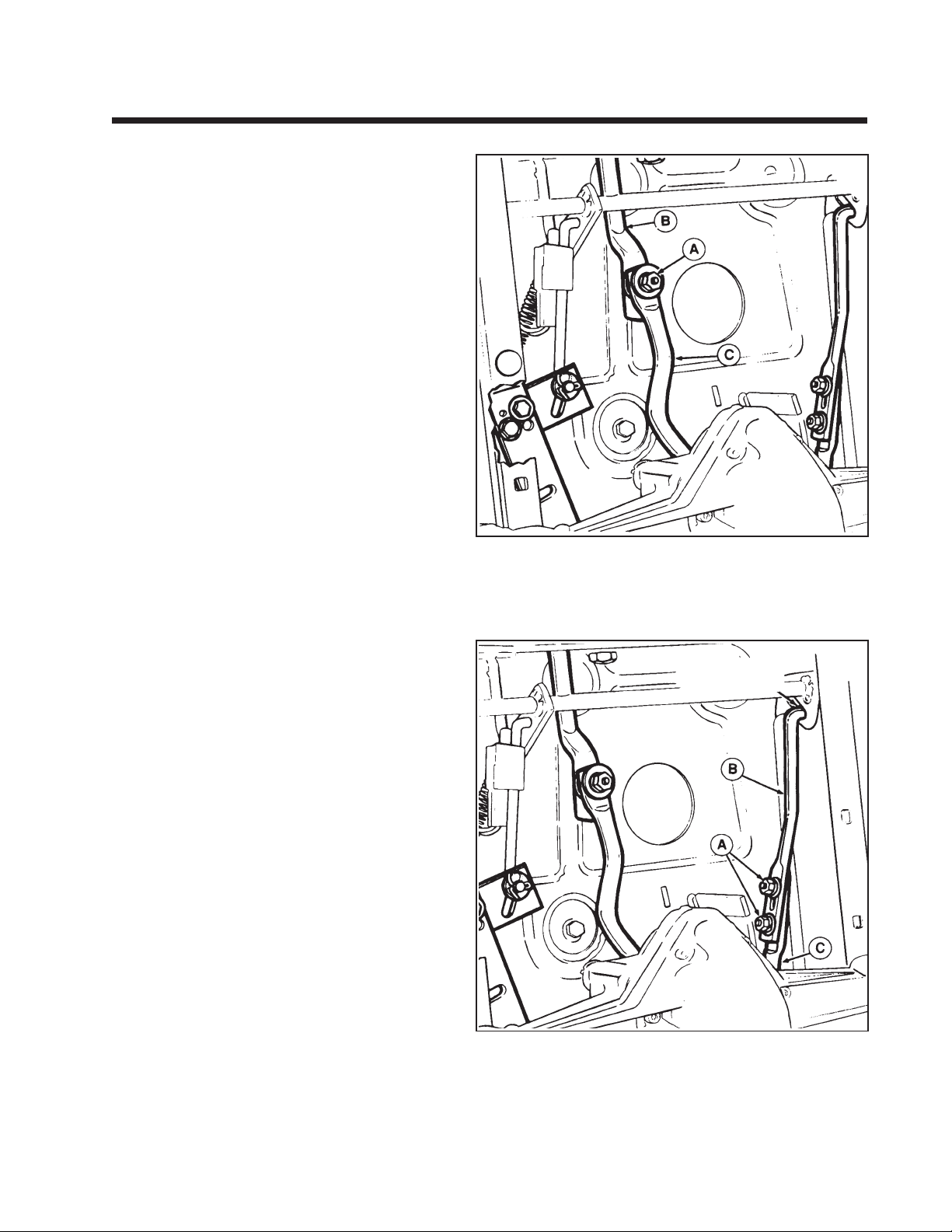
Section 11.
Mid-Engine Riding Mowers with HydroGear 311-0500
Neutral Adjustment
Perform the following adjustment if the shift lever
must be moved out of the neutral gate to prevent
forward or reverse rider movement. With the shift
lever in the neutral gate and the clutch/brake pedal
released, a small amount of travel in the shift lever
may be required to fully stop rider.
1. Position rider on flat level ground and start rider.
2. With engine running, position the shift lever so
that the rider has no forward or reverse movement (shift lever may not necessarily be in the
neutral gate). Shut off the rider engine and do not
depress clutch/brake pedal or move shift lever.
Alternate method: Raise rear wheels off ground
and support rider frame with jackstands. Move
shift lever forward and reverse and then move
shift lever so that rear wheels do not rotate.
3. Loosen the nut (A, figure 11-1) that secures the
front hydro control rod (B) to the rear rod (C).
Control rod must be free to move. If performing
the return-to-neutral adjustment, loosen the two
nuts (A, figure 11-2) that secure the front returnto-neutral rod (B) to the rear rod (C). Front
return-to-neutral rod must be free to move.
4. Move the shift lever into the neutral gate.
5. Tighten the nut (A) securely to 17 ft. lbs.
6. Check operation of rider for any movement with
shift lever in neutral gate. Perform the return-toneutral adjustment (refer to following paragraph).
*2425
Figure 11-1. Neutral Adjustment
A. Nut
B. Front Hydro Control Rod
C. Rear Hydro Control Rod
*2425
Return to Neutral Adjustment
Perform the following adjustment if the shift lever
does not return to the neutral gate when the clutch/
brake pedal is fully depressed. Make sure the front
hydro control rod (B, figure 11-1) is lubricated and
does not bind in the carrier frame hole.
1. Make sure the Neutral Adjustment is correct
(refer to preceding paragraph).
2. Loosen the two nuts (A, figure 11-2) that secure
the front return-to-neutral rod (B) to the rear rod
(C). Front return-to-neutral rod must be free to
move.
3. Place the shift lever in the full forward position
(highest ground speed setting in the transport
quadrant).
4. Move the front return-to-neutral rod all the way
rearward in the slot to shorten the length of the
assembled return-to-neutral rods. Tighten the
two nuts (A) with rods in this position.
5. Start the rider and check the return-to-neutral
operation.
Figure 11-2. Return-to-Neutral Adjustment
A. Nut
B. Front Return-to-Neutral Rod
C. Rear Return-to-Neutral Rod
33
Page 38

INDEX
Numerical Index by Manufacturing Number
Mfg No Section Page Mfg No Section Page Mfg No Section Page Mfg No Section Page Mfg No Section Page
1690006 ..... 3...... 12
1690014 ..... 3...... 12
1690076 ..... 3...... 12
1690202 ..... 3...... 12
1690211 ..... 3...... 12
1690214 ..... 3...... 12
1690217 ..... 3...... 12
1690342 ..... 3...... 12
1690352 ..... 3...... 12
1690367 ..... 3...... 12
1690427 ..... 3...... 12
1690429 ..... 3...... 12
1690431 ..... 3...... 12
1690433 ..... 3...... 12
1690473 ..... 3...... 12
1690477 ..... 3...... 12
1690478 ..... 3...... 12
1690479 ..... 3...... 12
1690480 ..... 3...... 12
1690516 ..... 3...... 12
1690519 ..... 3...... 12
1690569 ..... 3...... 12
1690570 ..... 3...... 12
1690571 ..... 3...... 12
1690572 ..... 3...... 12
1690574 ..... 3...... 12
1690575 ..... 3...... 12
1690638 ..... 3...... 12
1690640 ..... 3...... 12
1690642 ..... 3...... 12
1690723 ..... 3...... 12
1690727 ..... 3...... 12
1690759 ..... 8...... 30
1690763 ..... 8...... 30
1690810 ..... 8...... 30
1690846 ..... 8...... 30
1690853 ..... 8...... 30
1690868 ..... 8...... 30
1690875 ..... 8...... 30
1690881 ..... 8...... 30
1690887 ..... 8...... 30
1690890 ..... 3...... 12
1690894 ..... 3...... 12
1690912 ..... 8...... 30
1690919 ..... 8...... 30
1690936 ..... 8...... 30
1690947 ..... 8...... 30
1690954 ..... 8...... 30
1690960 ..... 8...... 30
1691017 ..... 2...... 11
1691018 ..... 2...... 11
1691019 ..... 2...... 11
1691020 ..... 2...... 11
1691029 ..... 8...... 30
1691032 ..... 8...... 30
1691033 ..... 8...... 30
1691040 ..... 8...... 30
1691043 ..... 8...... 30
1691044 ..... 8...... 30
1691122 ..... 3...... 12
1691124 ..... 3...... 12
1691139 ..... 3...... 12
1691234 ..... 8...... 30
1691235 ..... 8...... 30
1691236 ..... 8...... 30
1691237 ..... 8...... 30
1691250 ..... 2...... 11
1691263 ..... 5...... 17
1691271 ..... 8...... 30
1691276 ..... 8...... 30
1691307 ..... 2...... 11
1691331 ....10 .... 32
1691336 ....10 .... 32
1691340 ..... 8...... 30
1691357 ..... 2...... 11
1691362 ..... 8...... 30
1691380 ..... 2...... 11
1691381 ..... 2...... 11
1691382 ..... 3...... 12
1691383 ..... 3...... 12
1691387 ..... 2...... 11
1691389 ..... 2...... 11
1691391 ..... 2...... 11
1691392 ..... 2...... 11
1691397 ..... 2...... 11
1691432 ..... 8...... 30
1691470 ..... 5...... 17
1691471 ..... 5...... 17
1691473 ..... 8...... 30
1691475 ..... 8...... 30
1691477 ..... 8...... 30
1691479 ..... 8...... 30
1691528 ..... 2...... 11
1691560 ..... 5...... 17
1691649 ..... 8...... 30
1691655 ..... 9...... 31
1691656 ..... 9...... 31
1691659 ..... 9...... 31
1691660 ..... 9...... 31
1691682 ..... 5...... 17
1691710 ..... 2...... 11
1691717 ..... 3...... 12
1691718 ..... 3...... 12
1691732 ..... 5...... 17
1691766 ..... 5...... 17
1691769 ..... 5...... 17
1691795 ..... 6...... 21
1691807 ..... 6...... 21
1691817 ..... 6...... 21
1691824 ..... 5...... 17
1691841 ..... 1....... 6
1691842 ..... 1....... 6
1691843 ..... 1....... 6
1691844 ..... 1....... 6
1691845 ..... 1....... 6
1691846 ..... 1....... 6
1691876 ..... 1....... 6
1691882 ..... 1....... 6
1691886 ..... 6...... 21
1691888 ..... 6...... 21
1691924 ..... 2...... 11
1691926 ..... 2...... 11
1691931 ..... 7...... 25
1691933 ..... 7...... 25
1691953 ..... 2...... 11
1691955 ..... 2...... 11
1691957 ..... 3...... 12
1691960 ..... 3...... 12
1691964 ..... 1....... 6
1691965 ..... 1....... 6
1691966 ..... 1....... 6
1691967 ..... 1....... 6
1691968 ..... 1....... 6
1691969 ..... 1....... 6
1691970 ..... 1....... 6
1691971 ..... 1....... 6
1691972 ..... 1....... 6
1691973 ..... 1....... 6
1691974 ..... 1....... 6
1691975 ..... 1....... 6
1692006 ..... 4...... 13
1692014 ..... 9...... 31
1692022 ..... 9...... 31
1692036 ..... 4...... 13
1692042 ..... 4...... 13
1692044 ..... 4...... 13
1692053 ..... 7...... 25
1692057 ..... 7...... 25
1692071 ..... 6...... 18
1692073 ..... 6...... 18
1692075 ..... 6...... 18
1692076 ..... 6...... 18
1692130 ....11 .... 33
1692131 ..... 2...... 11
1692133 ..... 2...... 11
1692135 ..... 2...... 11
1692137 ..... 2...... 11
1692139 ..... 2...... 11
1692141 ..... 2...... 11
1692143 ..... 3...... 12
1692144 ..... 3...... 12
1692156 ..... 7...... 25
1692164 ..... 7...... 25
1692176 ....11 .... 33
1692182 ..... 6...... 18
1692184 ..... 6...... 18
1692259 ..... 7...... 27
1692261 ..... 6...... 19
1692263 ..... 7...... 27
1692265 ..... 6...... 19
1692279 ..... 6...... 19
1692281 ..... 6...... 19
1692283 ..... 6...... 19
1692285 ..... 6...... 19
1692309 ..... 9...... 31
1692310 ..... 9...... 31
1692311 ..... 9...... 31
1692312 ..... 9...... 31
1692354 ..... 7...... 28
1692375 ..... 9...... 30
1692385 ....11 .... 33
1692399 ....11 .... 33
1692403 ..... 7...... 27
1692412 ..... 7...... 27
1692414 ..... 6...... 19
1692416 ..... 6...... 19
1692420 ..... 6...... 19
1692430 ..... 6...... 19
1692432 ..... 6...... 19
1692436 ..... 6...... 19
1692440 ..... 4...... 13
1692442 ..... 4...... 13
1692446 ..... 4...... 13
1692448 ..... 4...... 13
1692450 ..... 3...... 12
1692452 ..... 3...... 12
1692454 ..... 2...... 11
1692456 ..... 2...... 11
1692458 ..... 2...... 11
1692460 ..... 2...... 11
1692491 ....11 .... 33
1692495 ..... 7...... 27
1692497 ..... 6...... 19
1692499 ..... 6...... 19
1692501 ..... 4...... 13
1692503 ..... 3...... 12
1692505 ..... 2...... 11
1692507 ..... 2...... 11
1692512 ..... 9...... 31
1692515 ....11 .... 33
1692519 ....11 .... 33
1692521 ..... 2...... 11
1692523 ..... 2...... 11
1692525 ..... 2...... 11
1692528 ..... 6...... 19
1692530 ..... 6...... 19
1692572 ..... 4...... 15
1692574 ..... 4...... 15
1692576 ..... 4...... 15
1692578 ..... 4...... 15
1692580 ..... 4...... 15
1692588 ..... 7...... 28
1692591 ..... 7...... 28
1692609 ..... 6...... 19
1692613 ..... 6...... 19
1692631 ..... 4...... 13
1692633 ..... 4...... 13
1692750 ....11 .... 33
1692762 ..... 7...... 28
1692772 ..... 6...... 19
1692774 ..... 6...... 19
1692776 ..... 6...... 19
1692784 ..... 4...... 15
1692786 ..... 4...... 15
1692788 ..... 4...... 15
1692796 ..... 3...... 12
1692798 ..... 3...... 12
1692809 ..... 6...... 19
1692811 ..... 6...... 19
1692813 ..... 6...... 19
1692815 ..... 6...... 18
34
Page 39

Notes
35
Page 40

Notes
36
 Loading...