

Page 1
OPERATOR’S
MANUAL
Table of Contents
DRIVEN
VACUUM COLLECTOR
36” BLOWER ASSEMBLY
MFG. NO. 1691356
42”
BLOWER ASSEMBLY
MFG. NO. 1691260
CART COLLECTOR
MFG. NO. 1691525
DECALS
SAFETY RULES
INSTALLATION - BLOWER ASSEMBLY, 36” MOWER - p. 3
INSTALLATION - BLOWER ASSEMBLY, 42” & 48” MOWERS - p.
INSTALLATION AND OPERATION - CART COLLECTOR - p. 8
OPERATING WITHOUT COLLECTION SYSTEM
OPERATING WITHOUT COLLECTION SYSTEM - 36” MOWER -
13
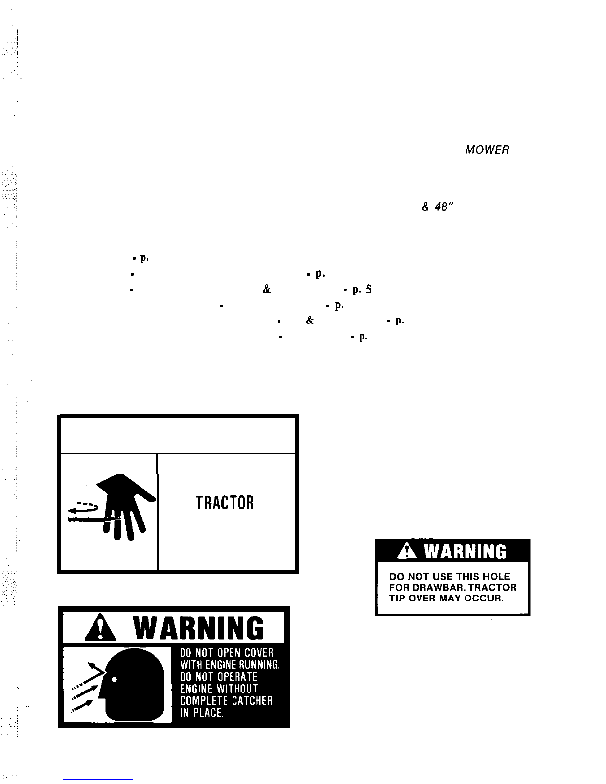
DECALS
A
DANGER
ROTATING BLADES
SHUT OFF MOWER
AN0
BEFORE SERVICING
OR CLEANING BLOWER
AND MOWER.
Part No. 1700259. Located on Blower
Part No. 1700346. Located on Bracket on Some
Models (Installed During Setup).
Part No. 1676923. Located on Collection System,
FORM 1701929-03
PRINTED IN U.S.A.
886
Page 2
Safety Rules
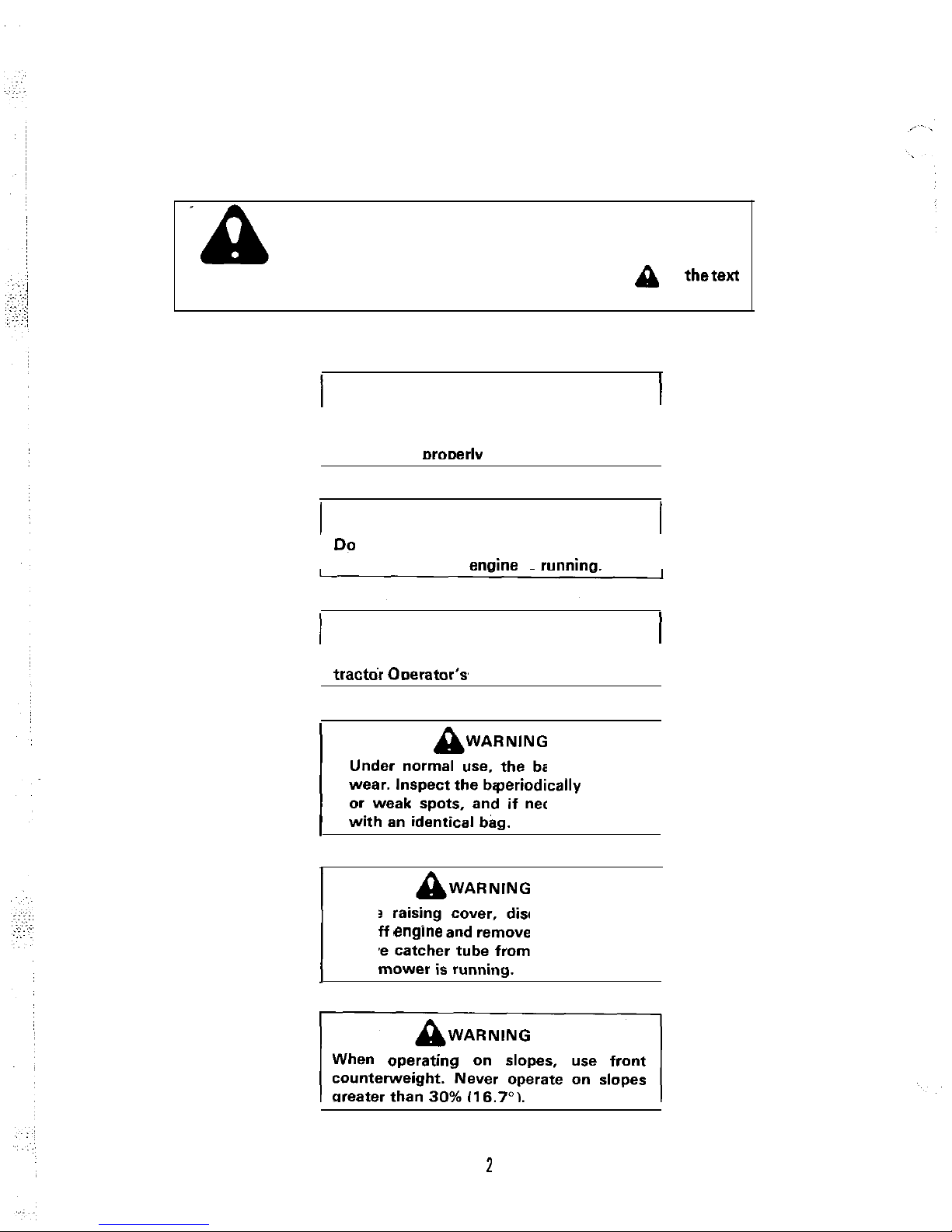
Read these safety rules and the safety rules in your Operator’s
Manual and follow them closely. Failure to obey these rules
could result in loss of control of vehicle, severe personal injury
to yourself, or damage to property or equipment. The triangle
in
signifies important cautions or warnings which must be followed.
A
WARNING
Do not operate the tractor unless the entire
grass catcher system or mower discharge
deflector is
installed.
A
WARNING
catcher while
the enoine
is
A
WARNING
Read and obey all safety warnings in your
Under normal use, the bag is subject to
wear. Inspect the bag
for wear
or weak spots, and if necessary, replace
Before raising cover. disengage mower,
while
turn off engme and remove the key. Do not
remove catcher tube from adapter or bag
When
on slopes, use front
counterweight. Never operate on slopes
Page 3
INSTALLATION
BLOWER ASSEMBLY, 36” MOWER
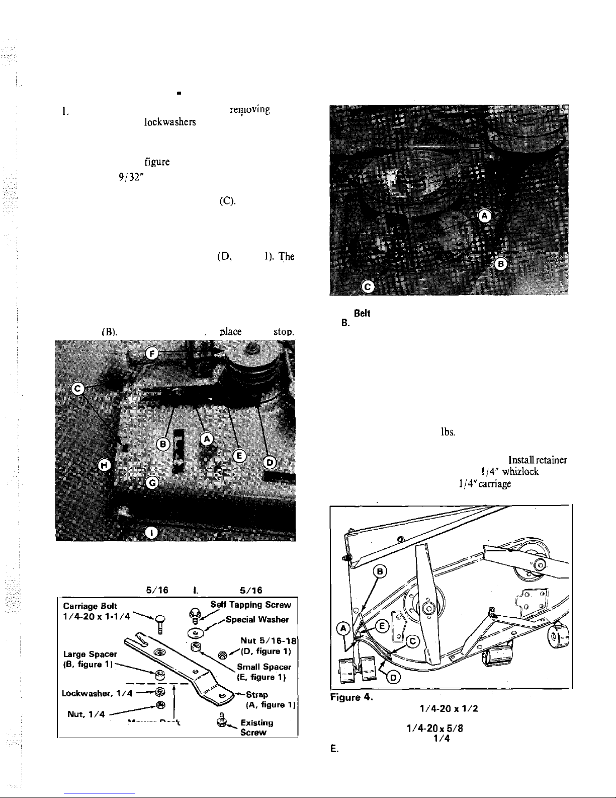
Remove the mower deflector by rerpoving two
carriage bolts, lockwashers and nuts. Save this
hardware for use when blower is removed for side
discharge.
2. Install strap (A,
a. Drill a
supplied template on the last page. Align template
with deflector mounting holes
b. Install strap (A, figure 1) to deck with hardware
shown in figure 2.
c. Check the installation. The strap should be
secured to deck with locknut (D, figure
The
small spacer (E) should be above the strap. The
large spacer (B) should be between strap and
mower deck.
3. The belt stop (A, figure 3) and hardware must be
relocated to hole (C) shown. Install self-tapping
screw
which was removed. in place of belt stop.
Figure 3.
A.
Stop
C. New Belt Stop Location
Figure 1.
E. Small Spacer
A. Strap
F. Pulley
6. Large spacer
G. Wing Nut
C. Holes, Deflector Mounting
H. Cup
D. Nut, Center Lock,
Locknut,
Center Lock
Mower Deck
Figure 2.
3
NOTE
To ease installation, engage PTO lever, so that
brake is away from pulley.
4. Remove the existing right-hand arbor pulley and
install the new double-groove pulley (F, figure I)
with existing capscrew, lockwasher and washer.
Torque to 55 to 70 ft.
Do not reinstall deck-drive
belt at this time.
5.
Install the baffle (B, figure 4) as shown. Installretainer
nut (E) in baffle, then screw the I/4” whizlock screw
(A) into retainer nut. Insert 1/4”caniage bolt (C) from
inside deck and install lockwasher and nut (D).
A. Screw. Whizlock.
6. Baffle.
C. Bolt, Carriage,
D. Lockwasher and Nut,
Retainer Nut
Page 4
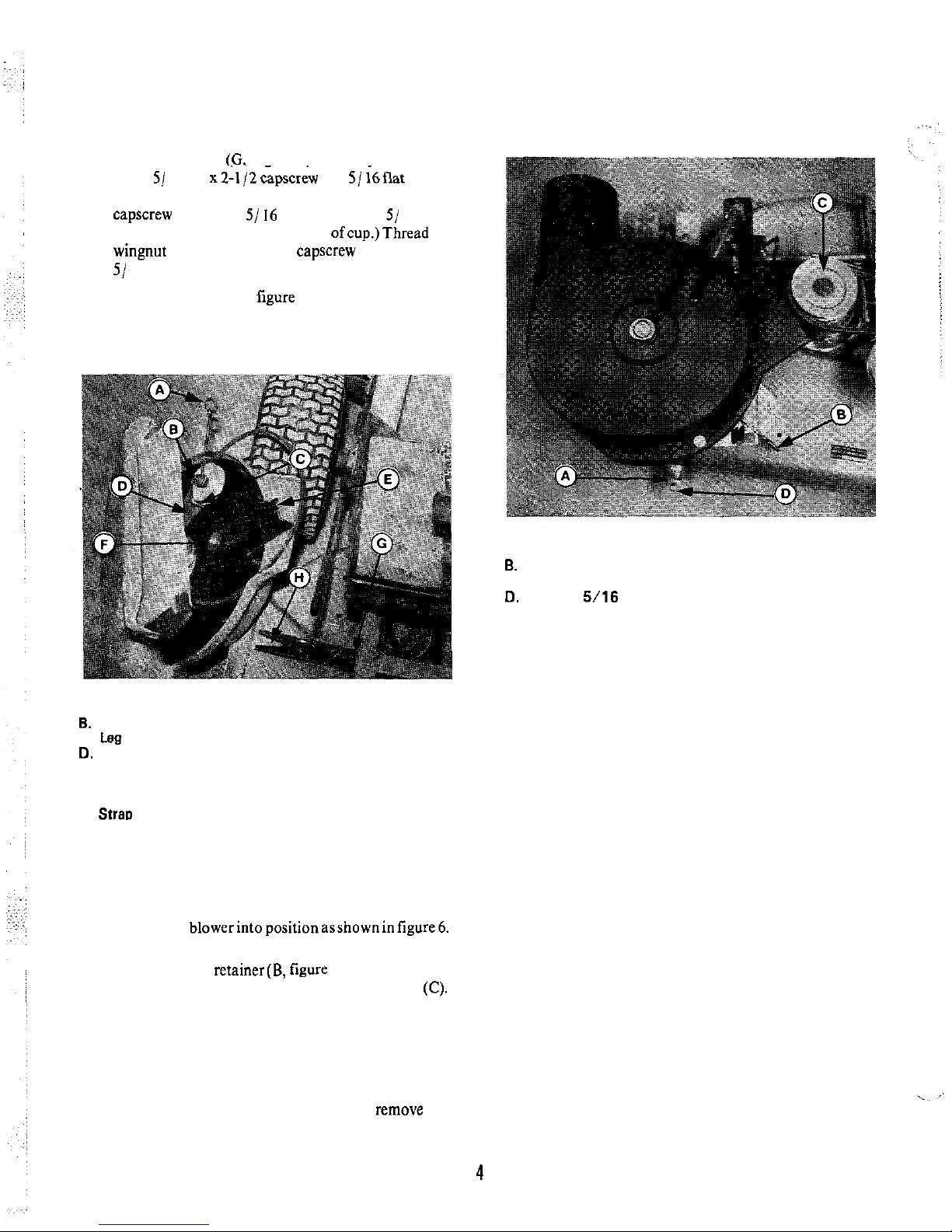
6. Install wing nut (G, figure I) assembly as follows.
Insert
16-18
and 5/
washer
from inside the deck. Place the cup (H) onto the
lockwasher and 5/ 16 nut.
(Figure 12 shows correct position ofcup.)Thread the
7.
The belt retainer (A, figure 5) must be positioned
correctly. Loosen the nut(B) and position the leg(C)
so it is against the side of the idler arm (D). Then,
tighten the nut (B).
Figure 6.
A. Wing Nut
c. Pulley
Figure 5.
A. Belt Retainer
Nut
c.
E. Notch
F. Spacer
G. Small Spacer
H. Stral, Notch
8. Install the blower assembly (figure 5) onto mower
deck as follows. Note that the notch(E) will be placed
onto small spacer(G) on top of the strap. The blower
assembly spacer(F) will tit into the strap notch(H).
a. Slide the
and tighten the wing nut (A).
b. Push the belt retainer(B, figure 6) to provide slack
and install belt onto lower groove in pulley
(Rotate pulley while placing belt on.)
9. Place the deck drive belt in the upper groove of the
pulley (C, figure 6).
10. This completes installation of the blower assembly.
Install the tube and collection system by following
directions provided in this manual. To
blower assembly, see “Operating Without Collection
System.”
Page 5
INSTALLATION
BLOWER ASSEMBLY, 42”
48” MOWER
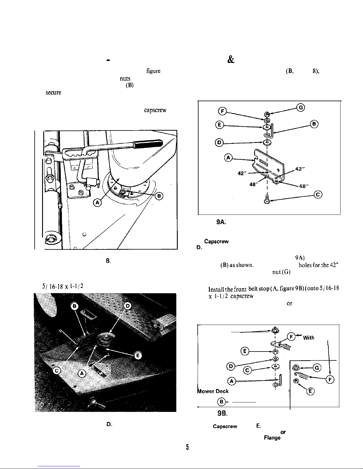
1. Remove the right-hand arbor cover (A,
7) by 4. Before installing arbor bracket (9, figure
remove
removing bolts, washers and nuts in front that hold
washer from underneath blade brake bracket (rear
cover to deck. Also, remove nut (9) and washers that
capscrew). Arbor bracket is same thickness as washer
rear tab to arbor.
and will replace washer.
2. Slip mower belt off the right hand pulley. Remove
the pulley from the arbor by removing
and
washers. Save washers for re-installation. Use wood
block to prevent blade from turning
Figure 7.
A. Arbor Cover
3.
Remove brake spring or spring anchor (if equipped)
and two self-tapping screws from arbor. Install two
capscrews (A, figure 8).
Figure 8.
A. Capscrews
B. Arbor Bracket
C. Notch
E. Belt Stop. Front
Figure
Arbor Bracket and Belt Stop
A. Arbor Bracket
B. Belt stop E. Large Washer
c.
F. Lockwasher
G. Nut
5. Install, the arbor bracket (A, figure 9A) and rear belt
stop (B)asshown. Note thedifferent holesforthe42”
and 48” mowers. Tighten nut(G) snug only-belt stop
will be adjusted in step 8.
6.
capscrew installed in step 3) as shown. If
removed, reinstall brake spring or spring anchor (F)
before flange nut(G). Tighten nut(E) snug only-belt
stop will be adjusted in step 8.
G
Mower Decks
Blade
Brake
Figure
Front Belt Stop
A. Belt Stop
B. Capscrew
C. Large Washer
F. Spring
Spring Anchor
D. Lockwasher
G.
Page 6

7.
Install new arbor
figure 8) with hubdown.
Use new 7/
capscrew and washers
removed in step 2. Torque to 55 to 60 ft.
Use
wood block to prevent blade from turning. It may be
necessary to add washer(s) (two provided) underneath the new pulley to properly align brake pad and
bottom groove. Refer to figure 9C.
8. Slip the mower drive belt onto the lower groove of
the new pulley (D. figure 8). With the belt engaged.
adjust the belt stops
from belt. Tighten the
hardware.
9. If mower is equipped with blade brake, adjust the
brake after installing new double groove pulley as
follows:
a. Engage the PTO lever. Be sure that mower drive
belt tension is correctly adjusted (see Operator’s
Manual).
b. Inspect the brake pad (A, figure 9C) to V-pulley
(B)
With PTO engaged, clearance
should be inch as shown in tigure 9C.
If adjustment is required. turn adjusting nuts (A,
figure 9D) until proper clearance is reached.
Figure 9C.
Bottom Groove Double
A.
Brake Pad
C. Washers (If Required)
A. Blade Brake Adjustment Nuts
IO. The baffle (E, figure
is installed in the blower
housing for use with 42” mower. For
with 48”
mower, remove the baffle and install in hole marked
48”.
Figure 10.
A. Blower Drive Belt ,
B. Idler Pull& E. Baffle
c. Spacer F. Driven
Pulley
D. Belt Guide
G. Notch
NOTE
On 42” and 48” mowers, the capscrew installed in
next step is used in the hole occupied by a screw
held in place by a retaining nut. (This screw secured
the right-front corner of the arbor cover.) Remove
this screw from mower deck by tapping out with a
hammer or prying off the retaining nut.
II. Install the belt
(B, figure II) with hardware
shown. Items E through M. (Figure I I shows blower
housing but it is not installed at this point of the
procedure.)
Install wing nut (N, figure II) as follows:
a. Remove existing hardware from front end of
stone guard.
b. From inside deck. install new 5/
carriage bolt (F. figure 12). Then install the cup
(A, figure
5/ 16 lockwasher (B), and 5/ 16 nut
Tighten the nut.
c. Thread the wing nut (D) far enough onto the
screw so that the 5/
locknut(E) can be threaded
on flush with the end of screw.
Page 7

Figure 11.
A. Blower Housing
B. Arbor Cover
C. Hook
D. Clip
E. Capscrew
F. Washer,
6
G. Washer.
6
H. Spacer
I. Lockwasher,
6
J. Nut.
K. Washer,
L. Washer,
M. Locknut,
N. Wing Nut
E
Figure 12.
A. Cup
B.
C. Nut.
E. Locknut,
F. Carriage Bolt
13.
Install the new baffle (A,
13) in deck on stone
guard using existing hardware. Hardware may be
installed with nut to inside or nut to outside.
7
Over Stone Guard
Figure 13.
A. Baffle B. Carriage Bolt C. Mower Discharge Opening
Install the blower assembly as follows.
a. Pivot cover (B, figure II) away to expose the
arbor.
b. Align the notch (G, figure IO) with spaceronarbor
bracket. Align spacer (C, figure
with etch (C.
figure 8) on arbor bracket. Slide the assembly into
place as shown in Figure
while aligning front
notch between cup and wing nut (D, figure
Tighten wing nut.
c. Place mower in low cut position. Raise the flap
(A, figure
and install the blower drive belt(D)
in the top groove of the pulley(B). (Pivot cover B.
figure I I. away to expose flap.)
d. Rotate the pivotingcover(B. figure I I) into place
and attach the hook (C) to the clip (D) on the
housing.
Figure 14.
A. Arbor Bracket
Figure 15.
A. Flap B.
Page 8

INSTALLATION AND OPERATION
CART COLLECTOR
ASSEMBLY
1.
Remove all parts from inside the cart’s box. Open the
bag of parts and sort the fasteners into groups for
easier assembly of the cart (figure 16).
2. Turn cart box’on one side.
a. Bolt U-bracket to bottom of box with two 5/ 16
lockwashers and nuts.
b. Bolt latch handle to front side of box. Place one
I long hex bolt with 5/16 flat washer
through the inside of the box. Next place a 5/ 16
flat washer, latch handle, 5/ 16 flat washer, spring
washer (side with grooves on outside), and
locknut. Tighten the locknut until the latch handle
slowly.
3. Bolt swivel wheel to the H-frame.
a. Place the head of the swivel (end with four slotted
holes) inSide the H-frame (side with the ends bent
upward).
b. Align the holes and place four
long hex
bolts with 3/8 flat washers throughthe head ofthe
swivel and frame.
Secure with four lockwashers and nuts.
4. Turn cart’s box upside down and install H-frame to
U-bracket.
a. Align the two ends of the H-frame (end with the
swivel wheel attached) to the U-bracket and
secure with two
boltsand
locknuts.
b. DO NOT over tighten the locknuts. The box
pivots at this point for dumping.
5. Turn latch handle to lock the H-frame to the cart’s
box and turn cart’upright.
LATCH HANDLE
2
Spring Washers .
2
Nuts
2 Each 5/16x
Round Head Bolt,
Lockwasher,
Nut
H-FRAME
SWIVEL WHEEL
4 Each
x 1 Hex Bolt, 3/B Flat Washer,
3/B Lockwasher, 3/B Nut
2 Each
x
Hex Bolt,
Locknul
Page 9

BRACKET INSTALLATION
The
which is bolted to the tractor’s back plate. The same
bracket is used on the riding mowers and the lawn
tractors. Once bolted in place, the bracket never needs to
be removed. For lawn tractors, see Section A. For
tractors with 3 forward speeds, see Section B.
Section A: Bracket Installation on Lawn Tractor
1.
Remove the drawbar plate from the back plate of the
lawn tractor.
2. Install the bracket (figure 17) to the back plate
through the same holes where the drawbar plate was
bolted. Use the
I hex bolts and
locknuts (A, figure 18).
Figure 18.
A. Hardware
Section B: Bracket Installation on Tractor with 3
Forward Speeds and 23” Diameter Rear Tires
1. Install the bracket to the back plate as shown in
figure 19, using three
I hex bolts and
locknuts. In the top, center hole (A) install a 3/8 x
used as a
A
CAUTION
Do not remove the existing drawbar. Do not use the
bracket as
Figure 19.
A. Top. Center Hole
2.
Install the decal, part number 1700346 (see first page)
to top of bracket beside hole (A, figure 19).
ASSEMBLY OF FRAME AND COVER
1. Install the frame (A, figure 20) at four locations (B)
with 5/16-18
capscrew, washer and nut.
Install spacers (F) at top capscrew on each side (see
8).
2. Attach the bracket (C, figure 20) with
5/
Figure 20.
A. Frame
C. Bracket
D.
E. Strap
F. Spacer
Page 10

3. The support rod and frame rod must be inserted into
the cover (A, figure 21) as follows.
a. The frame rod (C, figure 21) must be inserted
through the bottom sleeve of the cover so that the
two bent endsextend out openings, which
next
to the cord loops (D). The frame rod position is
indicated by dotted line (B, figure 22).
Figure 21.
A. Cover
Support Rod
C. Frame Rod
D. Cord Loops
E. Elbow
A.
Rod Location
E. Clip
Frame Rod Location F. Decal. Warning
C. Cord Loop
G. Tube
strap
H. Elbow
b. The support rod (B, figure
which has eyebolt
ends, must be threaded through the sleeve inside
the cover. The position is indicated by dotted line
(A,
NOTE
A
WARNING
When you pick up cover to place over the frame, be
sure support rod (B, figure 21) is inside frame rod
It is important for the operator’s safety, that the
warning decal he installed.
4. Insert the
5. Pick up the cover and place down onto
figure 20) inserting the elbow (A, figure 23) into the
bracket (B) (shown without cover for clarity). Pull
the rubber strap
bracket as shown.
Figure 23. (Shown without ccwer for clariw.)
A. Elbow
B. Bracket
c. strap
6.
On each side, place the eyebolt end of the support rod
(B, figure 21) onto the frame rod, then insert frame
rod (A, figure 24) through the frame (B). Insert clip
(C) through frame rod to secure.
7. Insert
22). Hook one end through washer (E, figure 22) and
pinch closed with a pliers.
8. Pull the cover down so it appears as in figure 22. To
secure the front, pull the cord loops (C) onto the
spacers. To secure the rear, hook the strap(D) onto
back of cart as shown.
9. Install warning decal (F, figure 22) so it is visible
from right-hand side. Make sure surface is clean.
Remove backing paper and tack edge of decal in
position. Then apply with heal of hand, smoothing
out bubbles. The edge of a ruler can also be used
Page 11

Figure 24.
A. Frame Rod
Frame
Maintenance
Clip
D. Support
Rod
A
WARNING
The cart cover is subject to wear and deterioration.
Check the
frequently. Use a” approved
replacement cover.
The
can be rinsed with a hose when dirty. A dirty
cover will inhibit the fast flow of grass clippings into the
cover. Do not leave grass or leaves in the cart for a long
period of time.
Operation’
A
WARNING
For safety reasons grass and debris
to he
removed only after engine is shut off, key removed,
and all moving parts ,stopped.
Before
cover, shut off
remove key,
BEFORE OPERATION
Clear the lawn of all sticks, stones, wire and,other debris
which may be caught or thrown by the mower blades.
Clean the tube with mild detergent (other products may
damage tube). The flow of grass can be seen through the
tube while moving.
Check grass condition. If wet, wait until later in the day.
If grass is wet plugging may occur.
For efficient bagging, air circulation under the mower
deck, through the chute and into the bag is very
important. For this reason, you should remove grass and
debris from underside of mower deck, discharge chute
and
The tube and elbow can be removed as an assembly for
cleaning.
INSTALLATION OF TRACTORS GRASS CHUTE
TO CART COLLECTOR
I Attach the hose to the blower housing
figure 25) and tighten with a screwdriver or wrench.
2. Insert the elbow (H, figure 22) onto the tube.
Figure 25.
A. Clamp
Hose
C. Wing Nut
OPERATION
WITH CART COLLECTOR
A
WARNING
Shut the tractor’s engine off before attaching,
adjusting, or disconnecting the
collector. Be
collector is in place
before
operating the tractor’s mower.
A
WARNING
Do not tow the cart collector on slopes greater than
15 degrees. Mow up
and down the face of slopes;
never
11
Page 12

1. Attaching:
a. Attach the cart to the tractor by aligning the two
ends of the H-frame to the holes in the bracket
(figure 26). Use the holes that will make the
level, Secure the cart to the bracket with twoclevis
pins and hairpin
b.
Attach the cart to the bracket at points‘%” or“C”.
3. Move the latch handle to the unlock position and
dump the cart’s box. The connecting tube will slide
off the elbow and the cart’s box will dump
a 90
degree angle for quick unloading.
4.
If bagging the grass clippings is desired, the grass can
be pulled from the cart at the curve side into a plastic
lawn bag. Also, the grass can be dumped onto a tarp
for throwing into a trailer.
Figure 26.
DUMPING GRASS AND LEAVES
1. Back the tractor to the desired place for unloading.
Shut the tractor’s engine off before getting off the
tractor’s seat.
2. Unhook the strap from the door lock and raise the
cover assembly to the open position. Lock the cover
in place by hooking the strap to the locking tab
(figure 27).
Figure 27.
A
WARNING
For safety
and debris
to be
removed only after engine is shut off, key removed,
and
moving
stopped.
A
WARNING
Before
and set
brake.
A
CAUTION
Do not haul sharp
cover.
5. The cover can be removed entirely from the cart.
Once the cover is removed, the
can be used for
hauling bulky loads.
A
CAUTION
Be sure to store the
in
safe place where it
cannot he torn.
OPERATING WITHOUT COLLECTION SYSTEM
48” MOWERS
A
WARNING
When blower assembly is removed from
deck, the deflector must be installed
described in
this section.
To operate without the grass collection system, remove
the blower assembly by removing the front wing nut (C,
figure 25) and slipping belt off of the pulley. Re-install the
mower deflector (figure 28) and the original hardware.
Install
carriage bolts from bottom and install
washers and nuts (A). Install the front washers (B) and
nut (C). Be sure flat washers and
all three locations.
Pivot the
(A, figure 29) over the arbor pulley and
hook into position.
12
Page 13

I
Figure
A. Nut
Washer
C. Nut
Figure 29.
A. Cover
Hook
OPERATING WITHOUT COLLECTION SYSTEM
36” MOWERS
To remove the blower assembly, first loosen the front
wing nut. To provide belt slack, push the belt
figure 6). Slip the belt off the pulley. The blower can be
removed from deck.
Install the mower deflector (A, figure 30) with two
carriage bolts, lockwashers and nuts.
Figure 30.
A. Deflector
13
Page 14

Page 15

EDGE OF DECK
Align with deflector mounting holes.
TEMPLATE FOR DRILLING MOUNTING HOLE
FOR 36” TURBO VAC.
Dia. Hole
Page 16

 Loading...