

Page 1
1
Installation
Instructions
44”Roller Bar Mower Kit
Part No. 1687077
For Conquest / 1700 / 2700 / YT / Broadmoor / 1600 / 2600 / LT
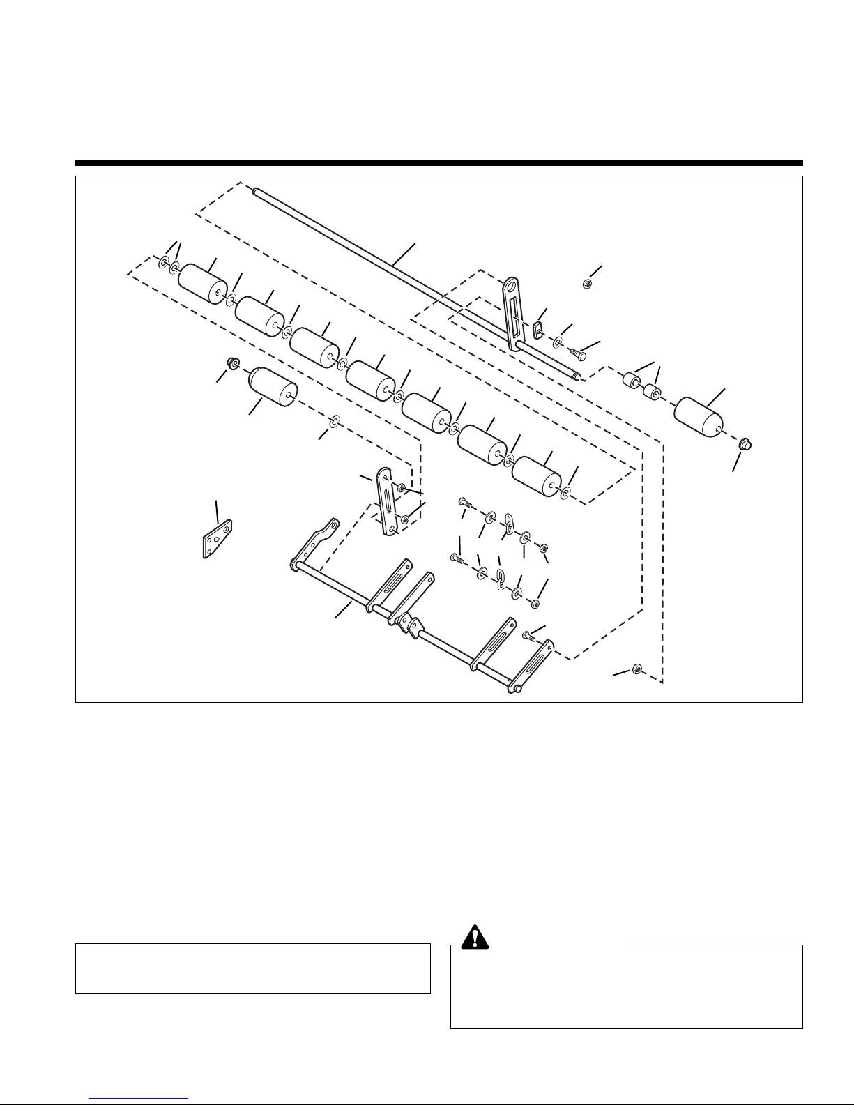
Figure 1. Kit Contents: 1687077
Ref Part No. Qty. Description
1 1716159A 1 ROLLER BAR, 44 Mower
2 2860681 2 LOCKNUT, Top Lock, 3/8-16
3 1677507 1 SLIDE
4 1924361 1 WASHER, 1/2
5 2172622 1 BOLT, Shoulder, 3/8-16 x 11/32
6 1924366 10 WASHER, 5/8
7 1722036 2 ROLLER
8 1960520 2 PUSH NUT, 5/8
9 1668513 7 ROLLER
10 1704074A 1 BAR
11 1931352 1 CARRIAGE BOLT, 3/8-16 x 1-1/2
12 1731383A 2 CAPSCREW, Hex, 5/16-18 x 1-1/2
13 1919381 4 WASHER, 5/16
14 1731384 2 LOCKNUT, ESNA, 5/16-18
15 1731383 2 CHAIN, 2 Link
16 1704080 1 PLATE, Support
17 1733521A 1 ROCKER SHAFT 44 Mower
18 1930644 2 LOCKNUT, 1/2-13
19 1602946 2 SPACER
This kit is is to convert a frame hung mower to a
roller bar mower.
1
6
2
3
4
5
2
16
11
10
17
6
8
7
6
12
19
7
8
14
9
Before beginning any service work turn off the
PTO, set the parking brake, turn off the ignition,
and disconnect the spark plug wire(s).
WARNING
6
9
6
9
6
9
6
9
6
9
6
9
18
13
15
13
Page 2
2
Installation Instructions Roller Bar Mower Kit
REMOVAL 44”FRAME HUNG
COMPONENTS
1. Disconnect hair pin (O, Figure 2) and clevis pin (R)
from adjustment rod (S). Remove adjustment rod (S)
from rocker arm assembly (T). Reconnect hair pin
(O) and clevis pin (R) into adjustment rod (S) to prevent loss.
2. Remove and retain 5/16-18 x 1-1/4 capscrews (A),
washer (B) and indicator (C). Remove and discard
wheel bracket (G).
3. Remove and retain 5/16-18 x 1-1/4 capscrews (J),
arm (K) and crank & trunnion assembly (I). Remove
and retain nut (N), lockwasher (M) and height of cut
plate (L).
C
B
A
G
I
J
K
L
Y
Figure 2. Remove Frame Hung
Components
A. Capscrews, 5/16-18 x 1-1/4
B. Washer, 5/16
C. Indicator
D. Capscrews & Locknuts
E. Hangers
F. Eccentric Nuts
G. Wheel Bracket Plate, RH
H. Wheel Bracket Plate, LH
I. Crank & Trunnion Assembly
J. Capscrews, 5/16-18 x 1-1/4
K. Arm
L. Height of Cut Plate
M. Lockwasher, 5/16
N. Nut, 5/16-18
O. Hair Pin
P. Locknuts, 1/2-13
Q. Stop, Height Of Cut
R. Clevis Pin
S. Adjustment Rod
T. Rocker Arm Assembly
U. Washer, 3/8, Small
V. Strap
W. Locknut, 3/8-16
X. Chains, 3 Link
Y. Upstop
Z. Washers
W
R
S
A
Q
O
D
M
P
N
4. Remove and discard 1/2-13 locknuts (P), stop (Q).
5. Remove and discard locknut (W) and wheel bracket
(H).
6. Remove and discard capscrew & nuts (D), washers
(Z), hangers (E). Retain the chains (X) and one of
the eccentric nuts (F).
6. Remove and retain straps (V), upstop (Z), washers
(U), and capscrews (A). Remove and discard rocker
arm assembly (T).
T
U
V
H
X
E
Z
F
D
D
X
E
F
D
Page 3

3
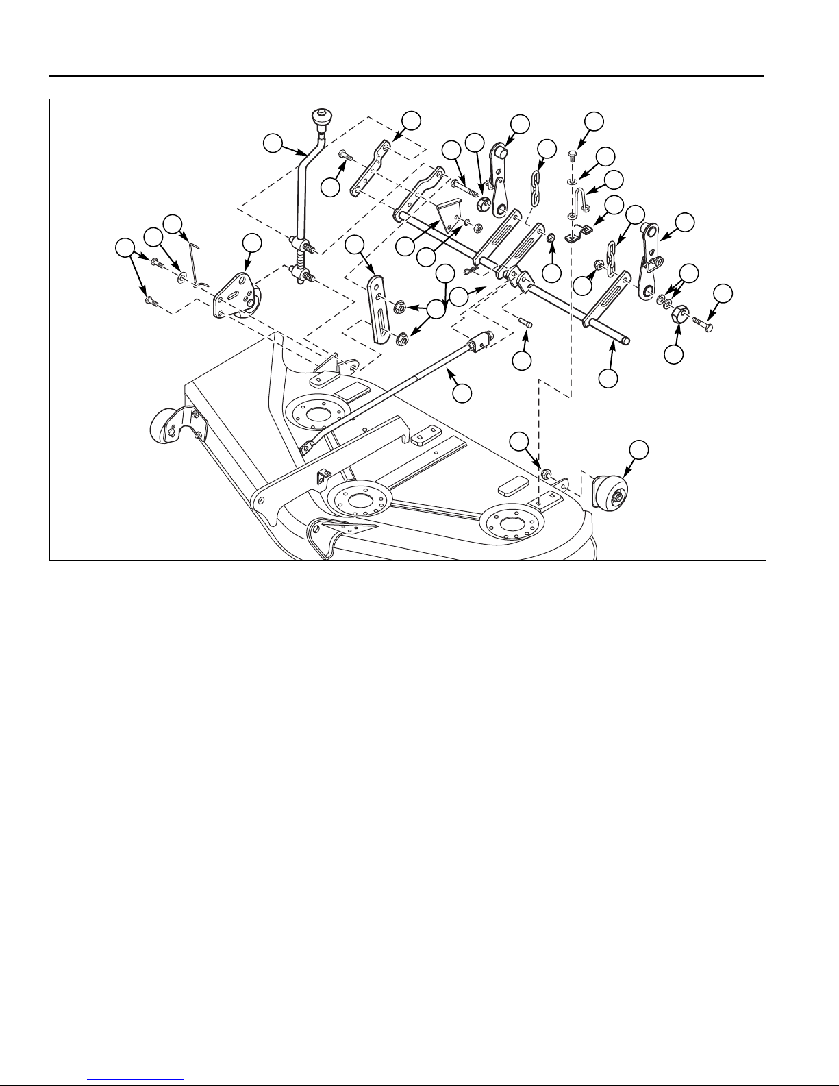
Roller Bar Mower Kit Installation Instructions
C
B
A
D
F
E
G
H
M
J
K
L
P
O
Figure 3. Installation 44” Rollers
A. Capscrews, 5/16-18 x 1-1/4
B. Washer, Large, 5/16
C. Indicator
D. Mower Support Plate
E. Crank & Trunnion Assembly
F. Capscrew, 5/16-18 x 1-1/4
G. Arm
H. Height of Cut Plate
I. Nut & Lockwasher
J. Hair Pin
K. Clevis Pin
L. Adjustment Rod
M. Rocker Arm Assembly
N. Straps
O. Locknuts, 1/2-13
P. Roller Bar Assembly
Q. Eccentric & Locknut, 3/8-16
R. Carriage Bolt, 3/8-16 x 1-1/2
S. Washer, Small, 5/16
T. Upstop
U. Capscrew, 5/16-18 x 1-1/2
V. Chain, 2 Link
W. Locknut, 5/16-18
X. Slide
Y. Washer, 1/2
Z. Shoulder Bolt, 3/8-16 x 1-11/32
I
Q
INSTALLATION 44”ROLLERS
1. Attach the rocker arm assembly (M, Figure 3) to the
mower deck with the straps (N), washers (S), upstop
(T), and capscrews (A). Apply a thin film of grease to
the inside of the straps.
2. Attach the chains (V) to the rocker arm assembly (M)
using 5/16-18 x 1-1/2 capscrews (U), washers (Y),
and 5/16-18 locknuts (W) as shown.
3. Place upper trunnion on crank & trunnion assembly
(E) through hole in rocker arm assembly (M) and
roller bar assembly (P) as shown. Secure with 1/2-13
locknut (O).
4. Place lower trunnion on crank & trunnion assembly
(C) through hole in mower deck and roller bar assembly (P) as shown. Secure with 1/2-13 locknut (O).
R
A
N
T
S
U
B
V
B
W
5. Connect the LH side roller bar assembly (P) to LH
side of rocker arm assembly (M) securing with 3/8-16
x 1-1/2 carriage bolt (R) and eccentric & 3/8-16 locknut (Q).
6. Connect the LH side roller bar assembly (P) to LH
side of mower deck securing with 3/8-16 x 1-11/32
shoulder bolt (Z), 1/2 washer (Y), slide (X), and 3/816 locknut (Q).
7. Attach height of cut plate (H) to rocker arm assembly
(M). Secure with 5/16-18 x 1-1/4 capscrews (F) and
nuts & washers (I).
8. Attach the mower support plate (D) and indicator (C)
to mower deck. Secure with 5/16 washer (B) and
5/16-18 x 1-1/4 capscrews (A).
9. Attach adjustment rod (L) to rocker arm assembly (M)
using clevis pin (K) and hair pin (J).
Z
Y
X
Q
U
B
V
B
W
Page 4

4
Installation Instructions Roller Bar Mower Kit
Removing the Mower Deck
1. Park the tractor, fully lower the attachment lift, turn off
the PTO, turn off the engine, remove the key, and
engage the parking brake. If equipped, pivot the
gauge wheels into sliding position.
2. Place mower in the lowest cutting position using the
mower height control.
3. Use the idler arm (D, Figure 4) to release tension on
the PTO belt, and remove belt from the PTO pulley.
4. Pull down on the lift hooks (A, Figure 4) and unhook
the lift chains (B).
5. Turn the wheels straight ahead. Pull back on springloaded lever (B, Figure 5) and lift mower hitch off of
the tractor brackets (A).
6. Turn wheels fully left, and slide mower deck out from
under the right side of the tractor.
WARNING
Engage parking brake, disengage PTO, stop
engine and remove key before attempting to
install or remove the mower.
Muffler and surrounding areas may be hot.
A
B
C
D
Figure 4. Mower Lift
A. Lift Hook C. PTO Belt
B. Lift Chain D. Idler Arm
MOWER DECK REMOVAL &
INSTALLATION
Chain Lift Models
CAUTION
The muffler and surrounding areas may be hot.
Page 5

5
Roller Bar Mower Kit Installation Instructions
A
B
Figure 5. Mower Hitch
A. Tractor Hitch Brackets
B. Spring-Loaded Lever
Installing the Mower Deck
NOTE: Perform mower installation on a hard, level surface such as a concrete floor.
1. Park the tractor, fully lower the attachment lift, turn off
the PTO switch, turn off the engine, remove the key,
and engage the parking brake. Turn the wheels fully
to the left.
2. Place mower in the lowest cutting position using the
mower height adjuster. Slide the mower deck under
the right side of tractor so that the mower hitch is
aligned with front tractor hitch (A, Figure 5).
3. See Figure 5. Turn wheels straight. Pull back on the
spring-loaded lever (B) while lifting up on the mower
hitch. Install the mower hitch onto tractor hitch brackets (A). When properly installed, the spring-loaded
lever should seat fully underneath the brackets (A).
4. See Figure 4. Connect the mower lift chains (B) to
the the tractor lift hooks (A).
NOTE 50” & 54” Mowers: The two-link lift chain is bolted
to the mower deck using the second link. This is correct
for most mowing applications.
5. See Figure 4. From left side of tractor, use the idler
arm (D) to relieve belt tension. Install belt (C) onto the
PTO pulley.
Page 6

6
Installation Instructions Roller Bar Mower Kit
Leveling The Mower
If the cut is uneven, the mower may need leveling.
Unequal or improper tire pressure may also cause an
uneven cut. Make sure tire pressure is correct as specified in Checking Tire Pressure.
SIDE-TO-SIDE LEVELING
1. With the mower installed, place the tractor on a
smooth, level surface such as a concrete floor. Turn
the front wheels straight forward.
2. Check for bent blades and replace if necessary.
3. Place the mower in mid-cut position. Arrange the outside mower blades so that they are pointing from
side-to-side.
4. Measure the distance between the outside tips of
each blade and the ground. If there is more than 1/8”
(3mm) difference between the measurements on
each side, proceed to step 5. If the difference is 1/8”
(3mm) or less, proceed to step 6.
ECCENTRIC NUT MODELS
5. See Figure 8. Loosen the outside nut (A). Turn the
eccentric nut (B) to raise or lower left-hand side of
mower. When mower is level, hold the eccentric nut
while tightening the outside nut.
NOTE: 44”, 50”, & 54” Mowers. When using a turbo collection system, raise the discharge side of the mower
approximately 1/4” (6mm) to compensate for turbo
assembly weight. Check the level of the cut grass and
adjust the 1/4” (6mm) measurement as necessary for a
smooth, even cut.
FRONT-TO-BACK LEVELING
NOTE: 54” mowers have two adjustment rods that
should be adjusted simultaneously.
6. Arrange the blades so they face front-to-back.
7. Measure the distance from the ground to the front tip
of the center blade, and from the ground to rear tips
of left-hand and right-hand blades.
Front tip of the center blade should be 1/4" (6mm)
higher than rear tips of left-hand and right-hand
blades. If not, proceed with steps 8 - 9.
8. To raise front of mower deck, loosen front nut (B) and
turn rear nut (A, Figure 10) against bracket. To lower
front of mower deck, loosen rear nut (A) and the
bracket will move backwards to lengthen rod.
Figure 8. Leveling The Mower Side-to-Side Eccentric
Nut Models
A. Outside Nut B. Eccentric Nut
Figure 10. Front to Back Leveling
A. Rear Nut B. Front Nut
A B
9. Re-check the blade measurement then tighten the
front nut (B) against the bracket to secure.
MANUFACTURING, INC.
500 N Spring Street / PO Box 997
Port Washington, WI 53074-0997 USA
Form No. 1727716
Revision:02
TP 200-4144-02-SK-SMAN
Briggs & Stratton Yard Power Products Group
Copyright © 2007 Briggs & Stratton Corporation
Milwaukee, WI USA. All Rights Reserved
B
A
 Loading...