

Page 1

OPERATOR’S
MANUAL
Broadmoor / 1600 / 2600 Series
16HP Tractors
Mfg. No. Description
1693580 Broadmoor, 16HP Hydro
1693596 1615H, 16HP Hydro
1693662 Broadmoor, 16HP Hydro (Export)
1693598 2615H, 16HP Hydro
16HP V-Twin Tractors
Mfg. No. Description
1693592 Broadmoor, 16HP V Hydro
1693594 Broadmoor, 16HP V Hydro (Export)
1693617 1616VH, 16HP V-Twin Hydro
1693622 2616VH, 16HP V-Twin Hydro
1693817 Broadmoor, 16HP V Hydro
1693819 Broadmoor, 16HP V Hydro (Export)
1693821 1616VH, 16HP V-Twin Hydro
1693823 2616VH, 16HP V-Twin Hydro
18HP V-Twin Tractors
Mfg. No. Description
1693600 Broadmoor, 18HP V Hydro
1693602 1618H, 18HP V-Twin Hydro
1693604 2618H, 18HP V-Twin Hydro
1693613 Broadmoor, 18HP V Hydro (Export)
38” Mower Decks
Mfg. No. Description
1692682 38” Mower Deck
1692683 38” Mower Deck
1693170 38” Mower Deck (Export)
1694061 38” Mower Deck
44” Mower Decks
Mfg. No. Description
1692684 44” Mower Deck
1692685 44” Mower Deck
1693171 44” Mower Deck (Export)
1694062 44” Mower Deck
50” Mower Decks
Mfg. No. Description
1693267 50” Mower Deck
1693283 50” Mower Deck (Export)
1693284 50” Mower Deck
1720413-06
(Supercedes 1720214 & 1720415)
Rev 6/2001
TP-100-2249-06-BM-SMA
Page 2

Page 3

1
Table of Contents
Troubleshooting, Adjustments & Service .......22
Troubleshooting the Tractor..................................22
Troubleshooting the Mower ..................................23
Steering Wheel Adjustment ..................................24
Seat Adjustment....................................................24
Steering Gear Adjustment.....................................24
PTO Clutch Adjustment ........................................25
Blade Brake Check .......................................25
Brake Adjustment..................................................26
Mower Adjustments ..............................................26
Cutting Height Adjustment ............................26
Leveling the Mower.......................................27
Transmission Drive Belt Replacement..................28
Mower Belt Replacement......................................29
38” Mower Drive Belt Replacement ..............29
44” & 50” PTO Belt Replacement .................30
44” & 50” Arbor Drive Belt Replacement.......31
Battery Service......................................................32
Checking the Battery Voltage ...........................32
Charging A Discharged Battery ........................32
Jump Starting with an Auxiliary Battery ............32
Headlight Replacement.........................................34
Dashlight Replacement.........................................34
Transmission Purging ...........................................34
Specifications ....................................................35
Common Replacement Parts............................36
Lawn Care & Mowing Information .............LC—1
International Symbols ................................LC—8
Technical Manuals ......................................LC—8
NOTE: In this manual, “left” and “right” are referred to as
seen from the operating position.
Identification Numbers........................................2
Safety Rules & Information.................................3
Features & Controls ............................................6
Control Functions....................................................6
Parking Brake / Cruise Control Knob Functions .....8
Dashboard Display Functions .................................8
Safety Interlock System ..........................................9
Operating the Tractor ........................................10
General .................................................................10
Checks Before Starting .........................................10
Starting the Engine ...............................................11
Stopping the Tractor & Engine..............................11
Driving the Tractor ................................................11
Mowing..................................................................11
Pushing the Tractor by Hand ................................11
Mower Deck Removal & Installation .....................12
Storage .................................................................14
Regular Maintenance ........................................15
Maintenance Schedule .........................................15
Checking Tire Pressures.......................................15
Checking/Adding Fuel...........................................16
Check / Change Transmission Oil ........................16
Accessing the Engine Compartment.....................17
Fuel Filter Replacement........................................17
Oil & Filter Change................................................17
Check / Change Air FIlter......................................17
Lubrication ............................................................18
Lubricate Rear Axes .............................................19
Battery Maintenance .............................................20
Checking Battery Fluid..................................20
Cleaning the Battery and Cables ..................20
Servicing the Mower Blades .................................21
Blade Brake Check ...............................................21
© Copyright 2001 Simplicity Manufacturing, Inc.
All Rights Reserved. Printed in USA.
TP 100-2249-06-BM-SMA
WARNING
Engine exhaust from this product contains
chemicals known, in certain quantities, to cause
cancer, birth defects, or other reproductive harm.
Page 4
2
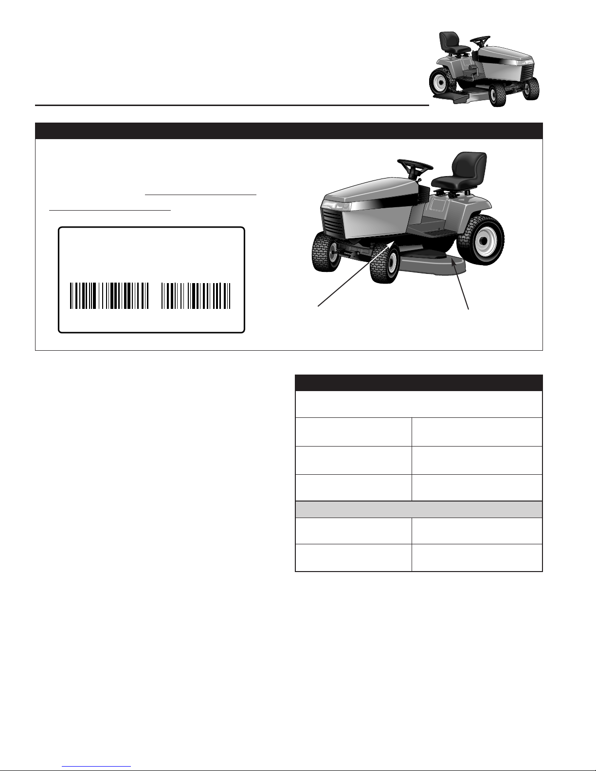
Identification
Numbers
169XXXX
MFG
Simplicity Manufacturing, Inc.
Port Washington, WI 53074-0997 U.S.A.
SERIAL
XXXXX
Mower Deck
Identification Tag
Unit
Identification Tag
SSAAMMPPLL
EE
When contacting your Authorized
Dealer for replacement parts, service,
or information YOU MUST HAVE
THESE NUMBERS.
IDENTIFICATION NUMBERS
Record your model name/number, unit and mower deck
manufacturer numbers and engine serial number in the
space provided for easy reference.
• The Unit I.D. tag is located on the left-side, of the
frame, as shown below.
• The Mower Deck I.D. tag is also on the left side, on
top of the mower deck.
• For location of Engine Serial Number, refer to the
Engine Owner’s Manual.
Be sure to fill out and return the Warranty Registration
Card supplied with your unit.
ENGINE REFERENCE DATA
Model Description Name/Number
Unit MFG
Number
PRODUCT REFERENCE DATA
Unit SERIAL Number
Dealer Name
Date Purchased
Engine Make
Engine Type/Spec
Engine Model
Engine Code/Serial Number
Mower Deck MFG Number
Mower Deck SERIAL
Number
IDENTIFICATION TAG LOCATIONS
Page 5

3
GENERAL OPERATION
• Read, understand, and follow all instructions in the manual and on
the unit before starting.
• Only allow responsible adults, who are familiar with the instructions, to operate the unit (local regulations can restrict operator
age).
• Clear the area of objects such as rocks, toys, wire, etc., which
could be picked up and thrown by the blade(s).
• Be sure the area is clear of other people before mowing. Stop unit
if anyone enters the area.
• Never carry passengers.
• Do not mow in reverse unless absolutely necessary. Always look
down and behind before and while travelling in reverse.
• Be aware of the mower discharge direction and do not point it at
anyone. Do not operate the mower without either the entire grass
catcher or the deflector in place.
• Slow down before turning.
• Never leave a running unit unattended. Always disengage the
PTO, set parking brake, stop engine, and remove keys before dismounting.
• Turn off the PTO switch to disengage the blades when not mowing.
• Stop engine before removing grass catcher or unclogging chute.
• Mow only in daylight or good artificial light.
• Do not operate the unit while under the influence of alcohol or
drugs.
• Watch for traffic when operating near or crossing roadways.
• Use extra care when loading or unloading the unit into a trailer or
truck.
• Data indicates that operators, age 60 years and above, are
involved in a large percentage of riding mower-related injuries.
These operators should evaluate their ability to operate the riding
mower safely enough to protect themselves and others from injury.
• Keep in mind the operator is responsible for accidents occurring to
other people or property.
• All drivers should seek and obtain professional and practical
instruction.
• Always wear substantial footwear and trousers. Never operate
when barefoot or wearing sandals.
• Before using, always visually check that the blades and blade hardware are present, in-tact, and secure. Replace worn or damaged
parts.
• Never operate the machine with defective guards, or without safety
protective devises in place.
• Disengage attachments before: refuelling, removing an attachment,
making adjustments (unless the adjustment can be made from the
operator’s position).
• When the machine is parked, stored, or left unattended, lower the
cutting means unless a positive mechanical lock is used.
• Follow the manufacturer’s recommendation for wheel weights or
counterweights.
SLOPE OPERATION
Slopes are a major factor related to loss-of-control and tip-over accidents,
which can result in severe injury or death. All slopes require extra caution.
If you cannot back up the slope or if you feel uneasy on it, do not operate
on it.
Control of a ride-on machine sliding on a slope will not be regained by the
application of the brake. The main reasons for loss of control are: insufficient tire grip on the ground, speed too fast, inadequate braking, the type
of machine is unsuitable for it’s task, lack of awareness of the ground conditions, incorrect hitching and load distribution.
Read these safety rules and follow them closely. Failure to obey these rules could result in loss of control
of unit, severe personal injury or death to you, or bystanders, or damage to property or equipment.
This mowing deck is capable of amputating hands and feet and throwing objects.
The triangle in text signifies important cautions or warnings which must be followed.
Safety Rules & Information
WARNING
Never operate on slopes greater than 17.6 percent
(10°) which is a rise of 3-1/2 feet (106 cm) vertically in
20 feet (607 cm) horizontally.
When operating on slopes use additional wheel
weights or counterweights. See your dealer to
determine which weights are available and
appropriate for your unit.
Select slow ground speed before driving onto slope.
In addition to front and rear weights, use extra caution
when operating on slopes with rear-mounted grass
catcher.
Mow UP and DOWN the slope, never across the
face, use caution when changing directions and DO
NOT START OR STOP ON SLOPE.
Do
• See your authorized dealer for recommendations of wheel weights
or counterweights to improve stability.
• Mow up and down slopes, not across.
• Remove obstacles such as rocks, tree limbs, etc.
• Watch for holes, ruts, or bumps. Uneven terrain could overturn the
unit. Tall grass can hide obstacles.
• Use slow speed. Tires may lose traction on slopes even through
the brakes are functioning properly. Choose a low gear so that you
will not have to stop or shift while on the slope.
• Use extra care with grass catchers or other attachments. These
can change the stability of the unit.
• Keep all movement on the slopes slow and gradual. Do not make
sudden changes in speed or direction.
• Always keep unit in gear especially when traveling downhill. When
clutching, release clutch slowly.
Do Not
• Do not start or stop on a slope. If tires lose traction, disengage the
blade(s) and proceed slowly straight down the slope.
• Do not turn on slopes unless necessary, and then, turn slowly and
gradually downhill, if possible.
• Do not mow near drop-offs, ditches, or embankments. The mower
could suddenly turn over if a wheel is over the edge of a cliff or
ditch, or if an edge caves in.
• Do not mow on wet grass. Reduced traction could cause sliding.
• Do not try to stabilize the unit by putting your foot on the ground.
• Do not use grass catchers on steep slopes.
• Do not mow slopes you cannot back up.
• Do not shift to neutral and coast down hill.
Page 6

4
Safety Rules
Slope Operation Continued
Children
Tragic accidents can occur if the operator is not alert to the presence of
children. Children are often attracted to the unit and the mowing activity.
Never assume that children will remain where you last saw them.
• Keep children out of the mowing area and under the watchful care
of another responsible adult.
• Be alert and turn unit off if children enter the area.
• Before and during reverse operation, look behind and down for
small children.
• Never carry children. They may fall off and be seriously injured or
interfere with safe unit operation.
• Never allow children to operate the unit.
• Use extra care when approaching blind corners, shrubs, trees, or
other objects that may obscure vision.
TOWING
• Never allow children or others in or on towed equipment.
• Tow only with a machine that has a hitch designed for towing. Do
not attach towed equipment except at the hitch point.
• Follow the manufacturer’s recommendations for weight limit for
towed equipment and towing on slopes.
• On slopes, the weight of the towed equipment may cause loss of
traction and loss of control.
• Travel slowly and allow extra distance to stop.
• Do not shift to neutral and coast down hill.
TRANSPORTING AND STORAGE
• Always observe safe refueling and fuel handling practices when
refueling the tractor after transportation or storage.
• Always follow the engine manual instructions for storage preparations before storing the tractor for both short and long term periods.
• Always follow the engine manual instructions for proper start-up
procedures when returning the unit to service.
• Never store the unit or fuel container inside where there is an open
flame or pilot light, such as in a water heater. Allow unit to cool
before storing.
EMISSIONS
• Engine exhaust from this product contains chemicals known, in
certain quantities, to cause cancer, birth defects, or other reproductive harm.
• Look for the relevant Emissions Durability Period and Air Index
information on the engine emissions label.
WARNING
When transporting this tractor on an open trailer,
make sure unit is facing forward, toward the direction
of travel. If tractor is facing backward, wind lift could
cause damage to the hood.
SERVICE AND MAINTENANCE
• Use extra care in handling gasoline and other fuels. They are flammable and vapors are explosive.
a) Use only an approved container.
b) Never remove gas cap or add fuel with the
engine running. Allow engine to cool before refueling. Do not
smoke.
c) Never refuel the unit indoors.
• If fuel is spilled, do not attempt to start the engine but move the
machine away from the area of spillage and avoid creating any
source of ignition until petrol vapors have dissipated.
• Replace all fuel tank caps and fuel container caps securely.
• Never fill containers inside a vehicle or on a truck bed with a plastic
bed liner. Always place containers on the ground away from your
vehicle before filling.
• Remove gas-powered equipment from the truck or trailer and refuel
it on the ground. If this is not possible, then refuel such equipment
on a trailer with a portable container, rather than from a gasoline
dispenser nozzle.
• Keep nozzle in contact with the rim of the fuel tank or container
opening at all times until fueling is complete. Do not use a nozzle
lock-open device.
• If fuel is spilled on clothing, change clothing immediately.
• Maintain or replace safety and instruction labels as necessary.
• Never run a unit in an enclosed area.
• Keep nuts and bolts, especially blade attachment bolts, tight and
keep equipment in good condition.
• Never tamper with safety devices. Check their proper operation
regularly and make necessary repairs if they are not functioning
properly.
• Keep unit free of grass, leaves, or other debris build-up. Clean up
oil or fuel spillage.
• Stop and inspect the equipment if you strike an object. Repair, if
necessary, before restarting.
• Never make adjustments or repairs with the engine running unless
specified otherwise in the engine manufacturer’s manual.
• Grass catcher components are subject to wear, damage, and deterioration, which could expose moving parts or allow objects to be
thrown. Frequently check components and replace with manufacturer’s recommended parts, when necessary.
• Mower blades are sharp and can cut. Wrap the blade(s) or wear
gloves, and use extra caution when servicing them.
• Check brake operation frequently. Adjust and service as required.
• Use only factory authorized replacement parts when making
repairs.
• Always comply with factory specifications on all settings and
adjustments.
• Only authorized service locations should be utilized for major service and repair requirements.
• Never attempt to make major repairs on this unit unless you have
been properly trained. Improper service procedures can result in
hazardous operation, equipment damage and voiding of manufacturer’s warranty.
• On multiple blade mowers, take care as rotating one blade can
cause other blades to rotate.
• Do not change engine governor settings or over-speed the engine.
Operating the engine at excessive speed can increase the hazard
of personal injury.
• Disengage drive attachments, stop the engine, remove the key,
and disconnect the spark plug wire(s) before: clearing attachment
blockages and chutes, performing service work, striking an object,
or if the unit vibrates abnormally. After striking an object, inspect
the machine for damage and make repairs before restarting and
operating the equipment.
• Never place hands near the hydro pump cooling fan when the tractor is running. Cooling fan is located on top of the transaxle
Page 7
5
Safety Rules & Information
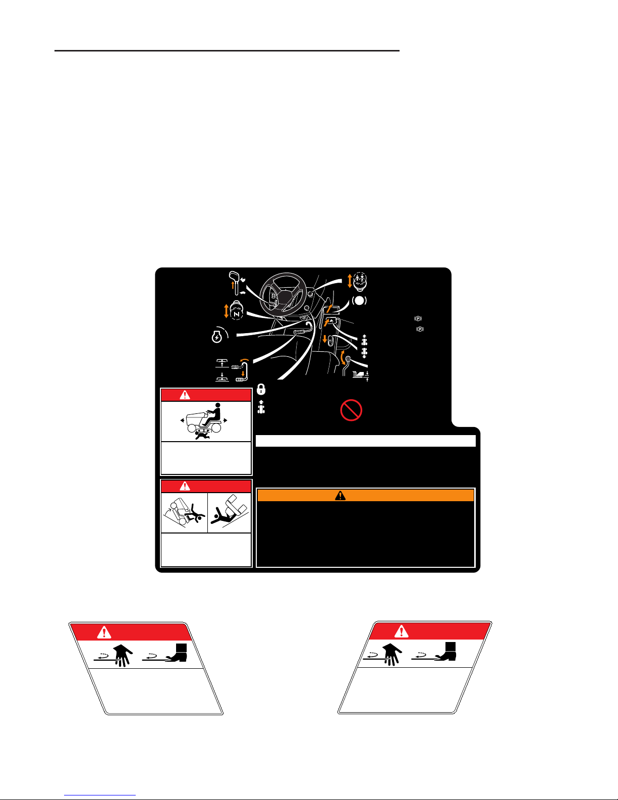
SAFETY DECALS
This unit has been designed and manufactured to provide you with the safety and reliability you would expect
from an industry leader in outdoor power equipment
manufacturing.
Although reading this manual and the safety instructions
it contains will provide you with the necessary basic
knowledge to operate this equipment safely and effectively, we have placed several safety labels on the unit to
remind you of this important information while you are
operating your unit.
All DANGER, WARNING, CAUTION and instructional
messages on your rider and mower should be carefully
read and obeyed. Personal bodily injury can result when
these instructions are not followed. The information is for
your safety and it is important! The safety decals below
are on your rider and mower.
If any of these decals are lost or damaged, replace them
at once. See your local dealer for replacements.
These labels are easily applied and will act as a constant
visual reminder to you, and others who may use the
equipment, to follow the safety instructions necessary for
safe, effective operation.
DANGER
ROTATING CUTTING BLADE
Do not put hands or feet
under mower deck while
blade is rotating.
1704276
DANGER
ROTATING CUTTING BLADE
Do not operate mower
without deflector or entire
grass catcher in place.
1704277
Decal - Danger
Part No. 1704276
Decal - Danger
Part No. 1704277
DANGER
OPERATING ON SLOPES
CAN BE DANGEROUS
SEE OPERATOR'S MANUAL.
IF YOU CANNOT BACK-UP A HILL
—DO NOT DRIVE ON IT.
AVOID SERIOUS INJURY OR DEATH
• READ OPERATOR'S MANUAL(S).
• KNOW LOCATION AND FUNCTION OF ALL CONTROLS.
• KEEP SAFETY DEVICES (GUARDS, SHIELDS, & SWITCHES)
IN PLACE AND WORKING.
• REMOVE OBJECTS THAT COULD BE THROWN BY
THE BLADE.
• DO NOT MOW WHEN CHILDREN OR OTHERS
ARE AROUND.
• NEVER CARRY CHILDREN.
• LOOK DOWN AND BEHIND—BEFORE AND WHILE BACKING.
• AVOID SUDDEN TURNS.
• IF YOU CANNOT BACK UP A HILL
— DO NOT OPERATE ON IT.
• GO UP AND DOWN SLOPES, NOT ACROSS.
• IF MACHINE STOPS GOING UPHILL, STOP BLADE
AND BACK DOWN SLOWLY.
• BE SURE BLADE(S) AND ENGINE ARE STOPPED
BEFORE PLACING HANDS OR FEET NEAR BLADE(S).
• WHEN LEAVING MACHINE, SHUT OFF ENGINE,
REMOVE KEY, AND SET PARKING BRAKE.
WARNING
To Start Engine: When Operator Leaves Seat:
• Seat must be occupied, PTO switch off, and brake pedal
depressed, throttle at half to full, turn Ignition to START.
To STOP Engine:
• Engage parking brake, throttle at half to full, turn
Ignition switch to OFF.
• Engine will shut off if PTO is ON.
• Engine will shut off if parking brake is OFF.
Before Leaving Machine:
• Turn PTO switch OFF, shut off engine,
remove key, and set parking brake.
OPERATION
DO NOT TOW TRACTOR!
Damage may result to
hydrostatic transmission
1718209-02
ROTATING BLADES CUT OFF
ARMS AND LEGS
STOP MOWER WHEN CHILDREN ARE NEAR.
NO RIDERS — THEY FALL OFF.
DANGER
CUTTING HEIGHT ADJUST
• Turn clockwise to raise cutting height.
• Turn counter-clockwise to lower
cutting height.
CRUISE CONTROL
• To SET — depress front
ground speed pedal
to desired forward speed,
then pull knob UP.
• To RELEASE — depress
brake pedal or push knob
DOWN or depress front
ground speed pedal.
THROTTLE
• ALWAYS operate at full throttle.
• Shut OFF at half to full throttle.
MOWER LIFT LEVER
• Raise lever to lift mower
up for transport.
• Lower lever to place mower
into cutting position.
• Operator must be in seat.
• Pull UP to engage.
• Push DOWN to disengage.
TO OPERATE PTO CLUTCH
CHOKE
• Pull knob OUT to engage.
• Push knob IN to disengage.
IGNITION SWITCH
OFF
RUN
START
• Remove key before
leaving tractor.
GROUND SPEED CONTROL
• Depress front ground speed pedal
to increase forward ground speed.
• Depress rear ground speed pedal
to increase reverse ground speed.
BRAKE PEDAL
• Depress brake pedal to slow or stop
tractor motion.
• To SET Parking Brake — fully depress
brake pedal and pull knob UP.
• To RELEASE Parking Brake — depress
brake pedal and push knob DOWN.
Decal - Operating Instructions Bottom Panel
Part No. 1718209
Page 8
6
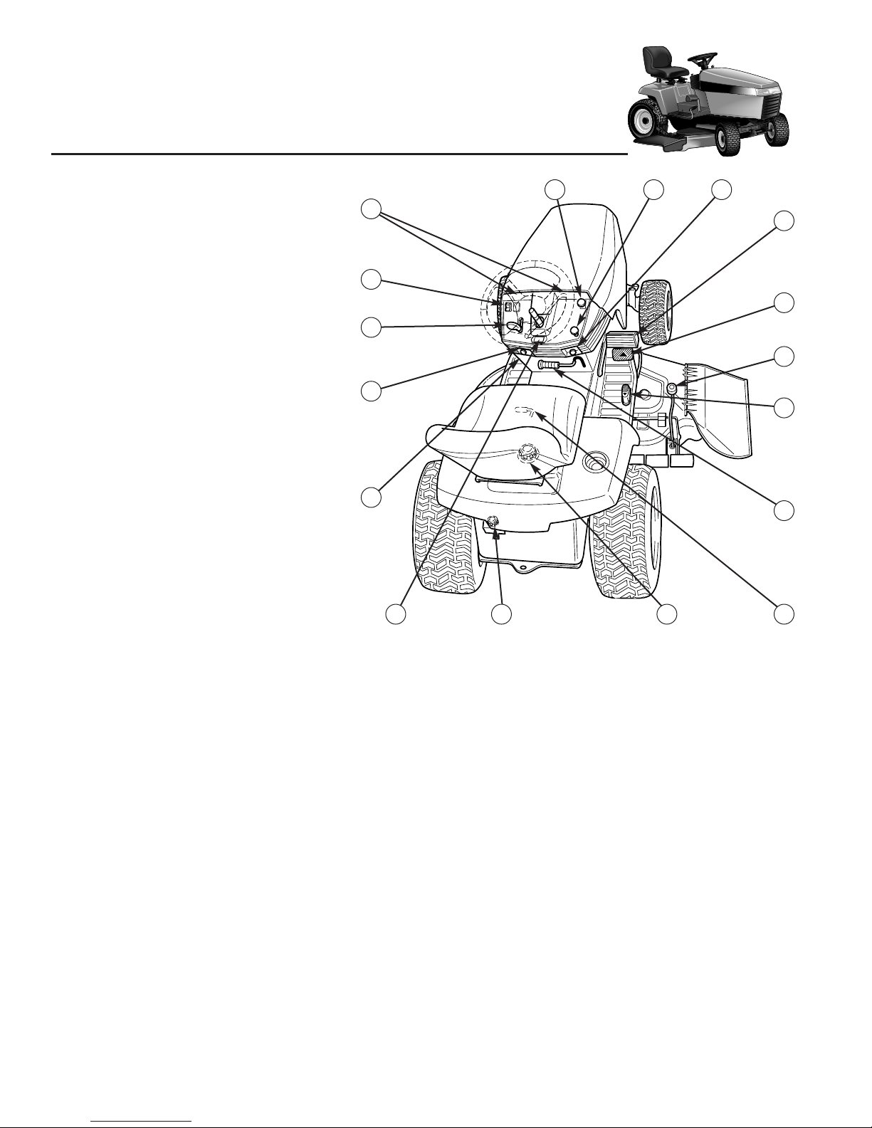
Features
& Controls
Figure 1. Tractor & Mower Controls
A. Choke (Twin Cylinder Models Only)
B. Throttle / Choke
C. Light Switch
D. Dashboard Display Lights
E. PTO Switch
F. Parking Brake / Cruise Control
G. Ignition Switch
H. Brake Pedal
I. Forward Ground Speed Pedal
J. Mower Height of Cut Adjust Knob
K. Reverse Ground Speed Pedal
L. Mower Lift Lever
M. Seat Adjustment Lever
N. Gas Cap / Gas Gauge
O. Transmission Oil Reservoir
P. Hour Meter
Q. Steering Wheel
A. Choke (Twin Cylinder Models Only)
Pulling the choke control OUT closes the choke for cold
starting.
A warm engine may not require choking.
B. Throttle / Choke Control
The throttle controls engine speed. Move the throttle forward to increase engine speed, and back to decrease
engine speed. Always operate at FULL throttle. On single cylinder models, moving the throttle control fully forward closes the choke.
A warm engine may not require
choking.
C. Light Switch
The light switch turns the tractor lights on and off.
D. Dashboard Display Lights
The dashboard display lights show a variety of engine
operation and control status information.
See page 8 for
more detailed information.
E. PTO Switch
The PTO (Power Take-Off) switch engages and disengages attachments that use the front PTO. To engage
the PTO, pull UP on the switch. Push DOWN to disengage.
Note that the operator must be seated firmly in the
tractor seat for the PTO to function.
F. Parking Brake / Cruise Control Knob
The parking brake / cruise control knob is used to lock
the parking brake when the tractor is stopped AND to
lock the cruise control when the tractor is in motion.
Fully depressing the brake pedal and pulling up on the
knob engages the parking brake.
Pulling up on the knob while depressing the forward
ground speed pedal engages the cruise control.
Refer to page 8 for a full explanation of parking brake /
cruise control functions.
E F G
C
A
P
Q
B
I
H
MN
J
K
L
O
CONTROL FUNCTIONS
The information below briefly describes the function of individual controls. Starting, stopping, driving, and mowing
require the combined use of several controls applied in specific sequences. To learn what combination and sequence
of controls to use for various tasks see the OPERATION section.
Please take a moment and familiarize
yourself with the name, location, and
function of these controls so that you will
better understand the safety and operating
instructions provided in this manual.
D
Page 9

7
G. Ignition Switch
The ignition switch starts and stops the engine, it has
three positions:
OFF Stops the engine and shuts off the
electrical system.
RUN Allows the engine to run and powers the
electrical system.
START Cranks the engine for starting.
NOTE: Never leave the ignition switch in the RUN position with the engine stopped–this drains the battery.
H. Brake Pedal
Depressing the brake pedal applies the tractor brake.
I. Forward Ground Speed Pedal
The tractor’s forward ground speed is controlled by the
forward ground speed control pedal.
Depress the pedal to increase FORWARD ground
speed. Note that the further down the pedal is
depressed, the faster the tractor will travel.
J. Mower Cut of Height Adjustment Knob
The cutting height adjustment knob controls the mower
cutting height. The cutting height is infinitely adjustable
between 1” and 3-5/8.”
K. Reverse Ground Speed Pedal
The tractor’s reverse ground speed is controlled by the
reverse ground speed control pedal (I, Figure 1).
Depress the REAR pedal to increase REVERSE ground
speed. Note that the further down the pedal is
depressed, the faster the tractor will travel.
Features & Controls
L. Mower Lift Lever
The mower lift lever raises the mower deck off the
ground for transporting. DO NOT cut with the lift lever in
the raised position.
M. Seat Adjustment Lever
The seat can be adjusted forward and back. Move the
lever, position the seat as desired, and release the lever
to lock the seat into position.
N. Gas Cap / Gas Gauge
The combination gas cap / gas gauge shows the amount
of fuel in the tank. To remove the cap, turn counterclockwise.
O. Transmission Oil Reservoir
The transmission oil reservoir holds “extra” oil for the
transmission. The oil level can be checked by looking at
the reservoir just beneath the fill cap.
P. Hour Meter
The hour meter shows the number of hours the key has
been in the RUN position.
Q. Adjustable Steering Wheel
The tractor is equipped with a two position steering column. See Adjustments section for adjustment procedure.
Page 10

0016
8
Features & Controls
Figure 4. Dashboard Display
DASHBOARD DISPLAY FUNCTIONS
Refer to Figure 4.
A. Headlight Indicator Light
Indicates that the headlights are on.
B. Low Oil Pressure Light
Kohler & Vanguard models only. Indicates that the
engine oil pressure is low.
C. Operator Seated Light
Indicates that the operator present seat switch has been
activated. This light must be lit for the engine to start.
D. Parking Brake / Cruise Control Light
Indicates that the parking brake or cruise control is
engaged.
E. PTO Light
Indicates the PTO switch is in the ON position.
F. Hour Meter
Shows the number of hours the key has been in the ON
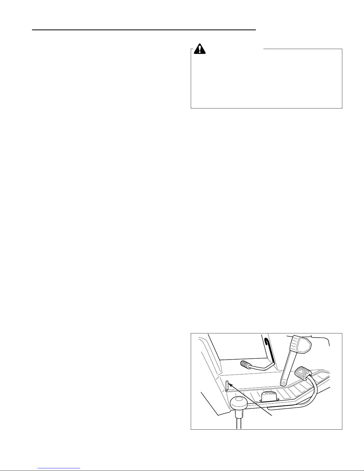
Figure 2. Engaging the Parking Brake
A. Ground Speed Pedals
B. Brake Pedal
C. Parking Brake / Cruise Control Knob
A
B
C
Figure 3. Cruise Control Function
A. Forward Ground Speed Pedal
B. Brake Pedal
C. Parking Brake / Cruise Control Knob
PARKING BRAKE / CRUISE
CONTROL KNOB FUNCTIONS
Applying the Parking Brake - See Figure 2. To lock
the parking brake, release the ground speed pedals (A),
fully depress the brake pedal (B), pull UP on the parking
brake / cruise control knob (C), and then release brake
pedal.
Releasing the Parking Brake - See Figure 2. To
release the parking brake, fully depress the brake pedal
(B) and push the parking brake / cruise control knob (C)
DOWN.
Applying the Cruise Control - See Figure 3. To apply
the cruise control, depress the forward ground speed
pedal (A) until the desired speed is achieved. Then pull
up on the parking brake / cruise control knob (B) and
release the forward ground speed pedal (A).
Releasing the Cruise Control - See Figure 3. The
cruise control can be released three ways:
1. Tap the forward ground speed pedal (A).
2. Push the parking brake / cruise control knob (C)
DOWN.
3. Depress the brake pedal (B).
In the event you need to stop quickly, fully depressing the brake pedal (B, Figure 2) will automatically
release the cruise control and stop the tractor.
For normal operation, it is recommended that you manually disengage the cruise control by tapping the forward
ground speed pedal or pushing the parking brake / cruise
control knob down.
A B C D E
F
A
B
C
Page 11

9
Features & Controls
SAFETY
INTERLOCK SYSTEM
This unit is equipped with safety interlock switches
and other safety devices. These safety systems are
present for your safety, do not attempt to bypass
safety switches, and never tamper with safety
devices. Check their operation regularly.
Operational SAFETY Checks
Your unit is equipped with a seat switch safety system. Check the seat switch operation every fall and
spring with the following tests.
Test 1 — Engine should NOT crank if:
• PTO switch is engaged, OR
• Brake pedal is not fully depressed (or parking
brake is not engaged), OR
• There is no operator in the seat.
Test 2 — Engine SHOULD crank if:
• PTO switch is NOT engaged, AND
• Brake pedal is fully depressed (or parking brake
is engaged), AND
• An operator is sitting in the seat.
Test 3 — Engine should SHUT OFF if:
• Operator rises off seat with PTO engaged, OR
• Operator rises off seat with brake pedal NOT
fully depressed (or parking brake disengaged).
Test 4 — Blade Brake Check
Mower blades and mower drive belt should come to
a complete stop within five seconds after electric
PTO switch is turned off (or operator rises off seat).
If mower drive belt does not stop within five seconds, see your dealer.
NOTE: Once the engine has stopped, the PTO
switch must be turned off after the operator returns
to the seat in order to start the engine.
WARNING
If the unit does not pass a safety test, do not
operate it. See your authorized dealer. Under
no circumstance should you attempt to
defeat the purpose of the safety interlock
system.
Page 12
10
GENERAL OPERATING SAFETY
Before first time operation:
• Be sure to read all information in the Safety and
Operation sections before attempting to operate this
tractor and mower.
• Become familiar with all of the controls and how to
stop the unit.
• Drive in an open area without mowing to become
accustomed to the unit.
Operating
the Tractor
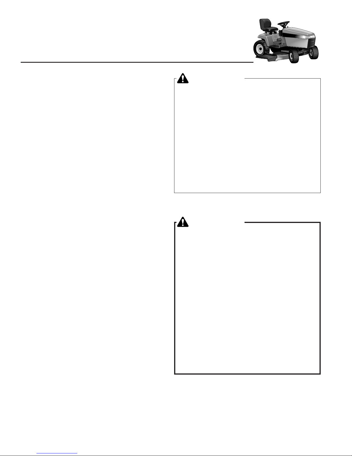
WARNING
Never allow passengers to ride on the unit.
Before leaving the operator’s position for any
reason, engage the parking brake, disengage the
PTO, stop the engine and remove the key.
To reduce fire hazard, keep the engine, tractor
and mower free of grass, leaves and excess
grease. Do not stop or park tractor over dry
leaves, grass or combustible materials.
Gasoline is highly flammable and must be
handled with care. Never fill the tank when the
engine is still hot from recent operation. Do not
allow open flame, smoking or matches in the
area. Avoid over-filling and wipe up any spills.
DANGER
OPERATING ON SLOPES
CAN BE DANGEROUS
Never operate on slopes greater than 17.6 % (10°)
which is a rise of 3-1/2 feet vertically in 20 feet
horizontally.
Operate the unit at a slow ground speed when
driving onto slope.
When operating on slopes that are greater than
15% (8.5°) but less than 17.6%, use additional
wheel weights or counterweights.
In addition to counterweights, use extra caution
when operating on slopes with rear-mounted
grass catcher. Mow UP and DOWN the slope,
never across the face, use caution when
changing directions and DO NOT START OR
STOP ON SLOPE.
CHECKS BEFORE STARTING
• Check that crankcase is filled to full mark on dipstick.
See the engine Operator’s Manual for instructions
and oil recommendations.
• Make sure all nuts, bolts, screws and pins are in
place and tight.
• Adjust the seat position, and make certain you can
reach all controls from operator’s position.
• Fill the gasoline tank with fresh gasoline. Refer to
engine manual for gasoline recommendations.
• Make certain rear counterweights are installed if you
will be operating the unit on sloping ground.
Page 13
MOWING
1. Engage the parking brake. Make sure the PTO
switch is disengaged.
2. Start the engine (see STARTING THE ENGINE).
3. Lower the mower lift lever.
4. Set the mower cutting height to the desired level.
5. Set the throttle to FULL.
6. Engage the front PTO (Mower Deck).
7. Begin mowing. See Section C for tips on mowing
patterns, lawn care, and trouble shooting information.
8. When finished, shut off the PTO and raise the mower
lift lever.
9. Stop the engine (see STOPPING THE TRACTOR
AND ENGINE).
11
Operating the Tractor
WARNING
If you do not understand how a specific control
functions, or have not yet thoroughly read the
FEATURES & CONTROLS section, do so now.
Do NOT attempt to operate the tractor without
first becoming familiar with the location and
function of ALL controls.
STARTING THE ENGINE
1. While sitting in the operator’s seat, fully depress the
brake pedal or set the parking brake.
2. Make sure that your feet are not depressing the
ground speed control pedals.
3. Disengage the PTO clutch.
4. Set the throttle to FULL.
5. Twin Cylinder Models: Pull the Choke knob OUT to
choke the engine.
NOTE: A warm engine may not require choking.
6. Insert the ignition key and turn it to START.
7. After the engine starts, move the engine throttle control to SLOW. Warm up the engine by running it for at
least a minute before engaging the PTO switch or driving the tractor.
NOTE: In the event of an emergency the engine can be
stopped by simply turning the ignition switch to STOP.
Use this method only in emergency situations. For normal engine shut down follow the procedure given in
STOPPING THE TRACTOR.
STOPPING THE TRACTOR & ENGINE
1. Disengaging the cruise control and taking your foot
off the ground speed control pedals will stop tractor
movement. For emergency stopping depress the
clutch / brake pedal.
2. Engage the parking brake.
3. Disengage the PTO.
4. Position the throttle control at half throttle.
5. Turn the ignition switch to STOP. Remove the key.
NOTE: Stopping the engine at speeds lower than half
throttle can cause engine damage. Do not stop the
engine with the throttle control in the IDLE position.
DRIVING THE TRACTOR
1. Sit in the seat and adjust the seat so that you can
comfortably reach all the controls and see the dashboard display.
2. Engage the parking brake.
3. Make sure the PTO switch is disengaged.
4. Start the engine (see STARTING THE ENGINE).
5. Disengage the parking brake and release the brake
pedal.
6. Depress the forward ground speed control pedal to
travel forward. Release the pedal to stop. Note that
the further down the pedal is depressed the faster the
tractor will travel.
7. Stop the tractor by releasing the ground speed control pedals, setting the parking brake, and stopping
the engine (see STOPPING THE TRACTOR AND
ENGINE).
Figure 5. Hydro Release Lever
Pull Lever Forward
to Release
PUSHING THE TRACTOR BY HAND
1. Disengage the PTO and turn the engine off.
2. Move the transmission release lever to PUSH position.
The tractor can now be pushed by hand. TOWING
THE TRACTOR WITH ANOTHER VEHICLE IS NOT
RECOMMENDED, AS THE TRANSMISSION MAY
BE DAMAGED.
Page 14

12
MOWER DECK REMOVAL &
INSTALLATION
Removing the Mower Deck
1. Park tractor on a hard, level surface such as a concrete floor. Turn off PTO switch and engine, remove
the key and apply parking brake.
2. Place mower in the lowest cutting position using the
mower height adjuster (B, Figure 6).
3. Place the mower lift lever (A, Figure 6) in the lowest
position.
4. Disconnect the mower lift arm from the tractor lift arm
(A, Figure 7). Re-install washer and safety clip.
5. Remove belt from PTO pulley (B, Figure 8).
6. Turn wheels straight ahead. Pull back on springloaded lever (B, Figure 9) and lift mower hitch off of
the tractor brackets.
7. Turn wheels fully left, and slide mower deck out right
side of tractor.
Operating the Tractor
WARNING
Engage parking brake, disengage PTO, stop
engine and remove key before attempting to
install or remove the mower.
CAUTION
The muffler and surrounding areas may be hot.
Figure 6. Raising & Lowering Mower
A. Mower Lift Lever B. Mower Height Adjuster
Figure 7. Lift Arms
(Viewed from underneath right side of tractor)
A. Mower Lift Arm C. Flat Washer
B. Tractor Lift Arm D. Safety Clip
Figure 9. Mower Hitch
A. Tractor Hitch Brackets
B. Spring-Loaded Lever
A
B
Figure 8. Removing & Installing Belt
A. Idler Arm B. PTO Pulley
B
A
C
D
A
B
A
B
Page 15

13
Operating the Tractor
Figure 13. Removing & Installing Belt
A. Idler Arm B. PTO Pulley
Figure 12. Lift Arms
(Viewed from underneath right side of tractor)
A. Mower Lift Arm C. Flat Washer
B. Tractor Lift Arm D. Safety Clip
Figure 11. Mower Hitch
A. Tractor Hitch Brackets
B. Spring-Loaded Lever
A
B
Installing the Mower Deck
1. Park tractor, shut off PTO and engine, remove the
key and apply parking brake. Turn the wheels fully to
the left.
2. Place mower height adjuster (B, Figure 10) in the
lowest cutting position. Place the mower lift lever in
the lowest position, also. Slide mower deck under
right side of tractor so that mower hitch is aligned with
front tractor hitch.
3. See Figure 11. Turn wheels straight. Pull back on the
spring-loaded lever (B) while lifting up on the mower
hitch. Install mower hitch onto tractor hitch brackets
(A). When properly installed, the spring-loaded lever
should seat fully underneath the brackets.
4. See Figure 12. Connect the mower lift arm (A) to the
tractor lift arm (B) using the flat washer (C) and safety
clip (D).
5. See Figure 13. Move idler arm (A) to relieve belt tension. Install belt onto the PTO pulley (B).
Figure 10. Raising & Lowering Mower
A. Mower Lift Lever B. Mower Height Adjuster
CAUTION
The muffler and surrounding areas may be hot.
WARNING
Engage parking brake, disengage PTO, stop
engine and remove key before attempting to
install or remove the mower.
B
A
B
A
C
D
B
A
Page 16

14
Operating the Tractor
WARNING
Never store the unit, with gasoline in engine or
fuel tank, in a heated shelter or in enclosed,
poorly ventilated enclosures. Gasoline fumes may
reach an open flame, spark or pilot light (such as
a furnace, water heater, clothes dryer, etc.) and
cause an explosion.
Handle gasoline carefully. It is highly flammable
and careless use could result in serious fire
damage to your person or property.
Drain fuel into an approved container outdoors
away from open flame or sparks.
STORAGE
Temporary Storage (30 Days Or Less)
Remember, the fuel tank will still contain some gasoline, so
never store the unit indoors or in any other area where fuel
vapor could travel to any ignition source. Fuel vapor is also
toxic if inhaled, so never store the unit in any structure used
for human or animal habitation.
Here is a checklist of things to do when storing your unit
temporarily or in between uses:
• Keep the unit in an area away from where children may
come into contact with it. If there’s any chance of unauthorized use, disconnect the spark plug wires.
• If the unit can’t be stored on a reasonably level surface,
chock the wheels.
• Clean all grass and dirt from the mower.
NOTE: If storing your tractor between winter snow removal
jobs in a cold area, we suggest that you fill the fuel tank at
the completion of each job to prevent water condensation in
the fuel tank. Wait for engine to cool before filling tank.
Long Term Storage (Longer Than 30 Days)
Before you store your unit for the off-season, read the
Maintenance and Storage instructions in the Safety Rules
section, then perform the following steps:
1. Drain crankcase oil and refill with a grade of oil that will
be required when unit is used again.
2. Prepare the mower deck for storage as follows:
a. Remove mower deck from the unit.
b. Clean underside of mower deck.
c. Coat all bare metal surfaces with paint or light coat of
oil to prevent rusting.
3. Clean external surfaces and engine.
4. Prepare engine for storage. See engine owner’s
manual.
5. Clean any dirt or grass from cylinder head cooling fins,
engine housing and air cleaner element.
6. Cover air cleaner and exhaust outlet tightly with plastic
or other waterproof material to keep out moisture, dirt
and insects.
7. Completely grease and oil unit as outlined in the Normal
Care section.
8. Clean up unit and apply paint or rust preventative to any
areas where paint is chipped or damaged.
9. Be sure the battery is filled to the proper level with water
and is fully charged. Battery life will be increased if it is
removed, put in a cool, dry place and fully charged
about once a month. If battery is left in unit, disconnect
the negative cable.
10. Drain fuel system completely or add a gasoline stabilizer
to the fuel system. If you have chosen to use a fuel stabilizer and have not drained the fuel system, follow all
safety instructions and storage precautions in this manual to prevent the possibility of fire from the ignition of
gasoline fumes. Remember, gasoline fumes can travel
to distant sources of ignition and ignite, causing risk of
explosion and fire.
NOTE: Gasoline, if permitted to stand unused for extended
periods (30 days or more), may develop gummy deposits
which can adversely affect the engine carburetor and cause
engine malfunction. To avoid this condition, add a gasoline
stabilizer to the fuel tank and run the engine a few minutes,
or drain all fuel from the unit before placing it in storage.
STARTING AFTER
LONG TERM STORAGE
Before starting the unit after it has been stored for a long
period of time, perform the following steps.
1. Remove any blocks from under the unit.
2. Install the battery if it was removed.
3. Unplug the exhaust outlet and air cleaner.
4. Fill the fuel tank with fresh gasoline. See engine
manual for recommendations.
5. See engine owner’s manual and follow all instructions
for preparing engine after storage.
6. Check crankcase oil level and add proper oil if
necessary. If any condensation has developed during
storage, drain crankcase oil and refill.
7. Inflate tires to proper pressure. Check fluid levels.
8. Start the engine and let it run slowly. DO NOT run at
high speed immediately after starting. Be sure to run
engine only outdoors or in well ventilated area.
Page 17
15
Regular
Maintenance
MAINTENANCE SCHEDULE & PROCEDURES
The following schedule should be followed for normal care of your tractor and mower. You will need to keep a record
of your operating time. Determining operating time is easily accomplished by multiplying the time it takes to do one
job by the number of times you’ve done the job, or you can install the optional hour meter.
* See the engine manufacturer's owner's manual.
** Change original engine oil after first 5 hours of operation.
*** More often in hot (over 85° F: 30° C) weather or dusty operating conditions.
**** Perform service after the first 50 hours of operation, then every 250 hours.
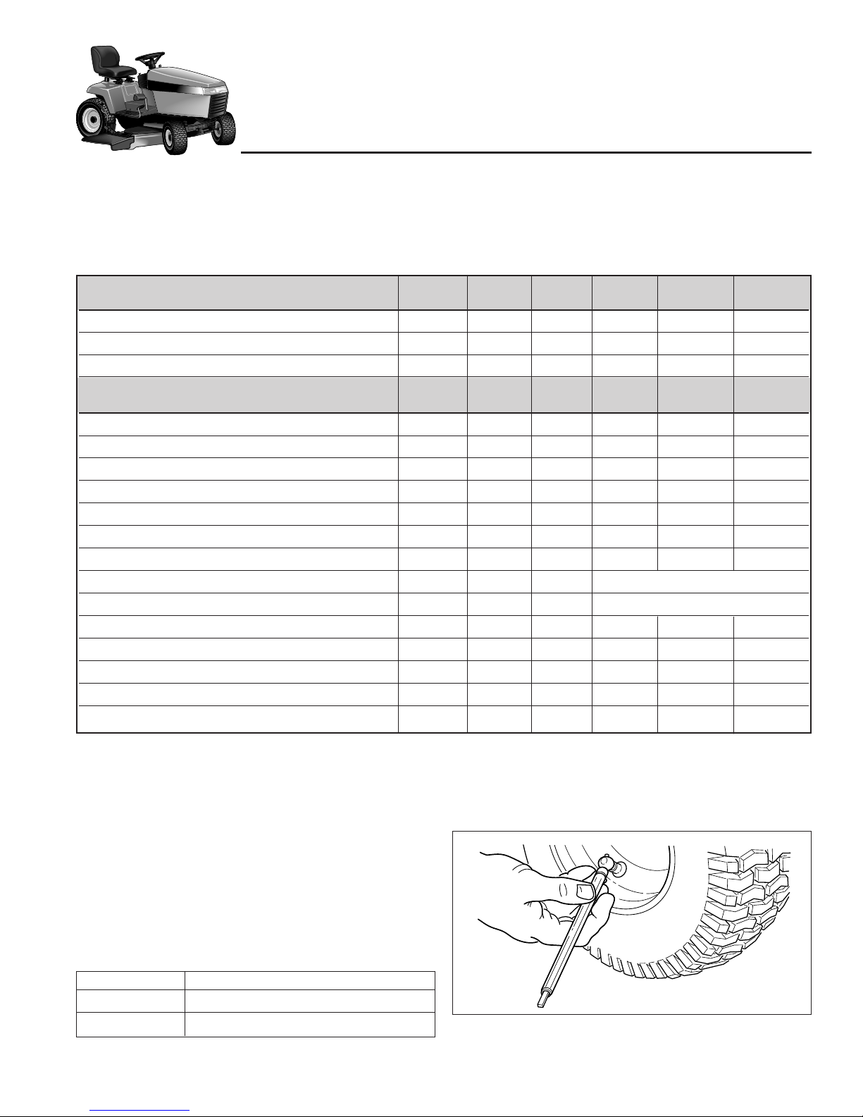
Tire Pressure
Front 12-15 psi (83-104 kPa)
Rear 6-8 psi (41-55 kPa)
Figure 14. Checking Tire Pressure
CHECK TIRE PRESSURES
Tire Pressure should be checked periodically, and maintained at the levels shown in the chart. Note that these
pressures may differ slightly from the “Max Inflation”
stamped on the side-wall of the tires. The pressures
shown provide proper traction, improve cut quality, and
extend tire life.
Before Before Every Every Every Spring
SAFETY ITEMS First Use Each Use 5 Hours 25 Hours 100 Hours & Fall
Check Safety Interlock System ●●
Check Tractor Brakes ●●
Check Mower Blade Stopping Time ●●
Before Before Every Every Every Spring
NORMAL CARE ITEMS First Use Each Use 5 Hours 25 Hours 100 Hours & Fall
Check Tractor/Mower for loose hardware ●●●
Check Engine Air Filter *, *** ●●
Check Engine Oil Level * ●● ●
Change Engine Oil & Filter *, **, *** ●●
Lubricate Tractor & Mower *** ●●
Check Tire Pressure ●● ●
Check Transmission Fluid ●●
Change Transmission Fluid **** Every 250 Hours
Check/Adjust PTO Clutch **** Every 250 Hours
Check Fuel Filter ●●
Clean Battery & Cables ●●
Clean & Sharpen Mower Blades ●●
Inspect Spark Plug(s) * ●●
Lubricate Rear Axle Shafts Yearly
Page 18

16
CHECKING / ADDING FUEL
To add fuel:
1. Remove the fuel cap (see A, Figure 15).
2. Fill the tank. Do not overfill. Leave room in the tank
for fuel expansion. Refer to your engine manual for
specific fuel recommendations.
3. Install and hand tighten the fuel cap.
CHECK / CHANGE
TRANSMISSION OIL
The transmission oil should be checked before each use,
and changed at the intervals shown or if it has become
discolored from overheating or contamination.
Service Interval: After initial 50 Hrs, then every 250 Hrs.
Oil Capacity: Apx. 3.5 Quarts
Oil Type: SAE 10W-30 with a minimum API rating
of SG/CD.
Checking the Oil Level:
1. Locate the reservoir tank on the rear of the unit.
Observe the oil level. Oil should be up to the FULL
mark (see Figure 16). DO NOT OVERFILL. Empty
space is required for heat expansion.
2. If necessary, clean the area surrounding the reservoir
cap, remove the cap, and add oil.
Changing the Transmission Oil:
1. Drain hydrostatic system by removing drain plug (see
Figure 17). Drain oil into a suitable container.
2. Reinstall the drain plug.
3. Add oil a few ounces at a time until the reservoir is
filled to the FULL mark. DO NOT OVERFILL. Empty
space is required for heat expansion.
4. Run tractor for several minutes and recheck the
transmission oil level. If the transmission is excessively noisy or unresponsive, perform the purging
procedure found in the Service section.
Regular Maintenance
WARNING
Gasoline is highly flammable and must be
handled with care. Never fill the tank when the
engine is still hot from recent operation. Do not
allow open flame, smoking or matches in the
area. Avoid over-filling and wipe up any spills.
Do not remove fuel filter when engine is hot, as
spilled gasoline may ignite. DO NOT spread hose
clamps further than necessary. Ensure clamps
grip hoses firmly over filter after installation.
Do not use gasoline containing METHANOL,
gasohol containing more than
10% ETHANOL, gasoline additives, or white
gas because engine/fuel system damage
could result.
Figure 15. Fuel Tank Fill
A. Fuel Tank Cap
A
FULL
Figure 16. Transmission Oil Reservoir
Full Mark
Figure 17. Transmission Drain Plugs
Do not allow dirt, water, or other debris to
enter the reservoir. Even a small amount of
dirt can irreparably damage the transmission
Drain
Plug
Page 19

17
Regular Maintenance
Figure 19. Engine Compartment
-Kohler Single Cylinder Engine
A. Battery D Oil Fill/Dipstick
B. Oil Filter E. Fuel Filter (Not Shown
C. Air Filter F. Throttle/Choke Cable
D
C
B
A
E
F
ACCESSING THE ENGINE
To gain access to the engine, unhook the rubber straps
(Figure 18) and tip the hood forward.
NOTE: For engine service item locations see Figure
20 for models with Briggs & Stratton engines and
Figure 19 for models with Kohler engines
FUEL FILTER REPLACEMENT
The fuel filter (E, Figures 19 and 20) is located in the fuel
line between the fuel tank and the carburetor.
If filter is dirty or clogged, replace as follows:
1. Disconnect the negative battery cable.
2. Place a container below the filter to catch spilled fuel.
3. Using a pliers, open and slide hose clamps from fuel
filter.
4. Remove hoses from filter.
5. Install new filter in proper flow direction in fuel line.
6. Secure with hose clamps.
7. Reconnect the negative battery cable when finished.
D
C
B
A
E
G
F
Figure 20. Engine Compartment
- Briggs & Stratton Twin Cylinder Engines
A. Battery E. Fuel Filter
B. Oil Filter F. Throttle Cable
C. Air Filter G. Choke Cable
D Oil Fill/Dipstick
Figure 18. Engine Access
Undo Hood
Straps (Both
Sides) and Lift
Hood to access
Engine
D
C
B
A
E
OIL & FILTER CHANGE
Refer to engine manual for specific oil and filter recommendations and oil draining procedures.
CHECK / CHANGE AIR FILTER
Refer to the engine manual for specific air filter service
procedures.
INSPECT & REPLACE SPARK PLUGS
Refer to the engine manual for specific spark plug
replacement procedures.
Page 20

18
Regular Maintenance
01
Figure 21. Lubricating the Tractor
LUBRICATION
Lubricate the unit at the locations shown in Figures 21
through 25 as well as the following lubrication points.
Grease:
• front axle pivot
• front axle grease fittings
• steering linkage
• foot pedal
• mower pivots
• mower arbors
• transmission idler assembly pivot
Use grease fittings when present. Disassemble parts
to apply grease to moving parts when grease fittings
are not present.
Not all greases are compatible. Simplicity Lithium
Grease is recommended, automotive-type lithium
grease may be used when this is not available.
Oil:
• hydro linkage
• seat adjustment assembly
• brake linkage
• frame pivot points
• mower deck height adjustment linkage
Generally, all moving metal parts should be oiled
where contact is made with other parts. Keep oil and
grease off belts and pulleys. Remember to wipe fittings and surfaces clean both before and after lubrication.
Figure 23. Brake Pedal Pivot Point
Figure 22. Lubricate Steering Linkage
Page 21

19
Regular Maintenance
Figure 25. Mower Lubrication Points
Figure 24. Arbor Lubrication Points
LUBRICATE REAR AXLES
We recommend removing the rear wheels and lubricating the axle shafts yearly. This prevents the wheel from
seizing onto the axle shaft, making future service easier.
1. Remove the key and disconnect the spark plug wire
while working on the unit.
2. Engage the parking brake and block the front wheels.
3. Using a jack or chain hoist positioned at the center of
the rear frame, carefully jack the unit up until the rear
tires are approximately 1" - 2" off the ground.
NOTE: For overall unit stability during service, do not
jack rear end higher than required for wheel removal.
4. Support the rear of the unit on jack stands positioned
under the rear frame (see Figure 26).
5. Remove the plastic hub cap (G, Figure 27).
6. Remove e-ring (F, Figure 27) using a screwdriver.
7. Remove the washers (D) and wheel (C).
NOTE: Your axle assembly may differ slightly from the
assembly pictured: washer (D, Figure 27) may be missing or doubled. This is adjusted on a tractor by tractor
basis during assembly to allow a small amount of axle
end-play.
8. Lubricate the axle shaft with anti-seize compound or
lithium grease.
9. See Figure 27 for assembly. Reinstall components in
reverse order of disassembly and lower the unit. Be
sure the key (H) is in place in the axle key-way.
Figure 26. Elevate the Rear End
Figure 27. Wheel and Axle Assembly
A. Washer E. Hub Cap Retainer
B. Spacer F. E-Ring
C. Wheel G. Hub Cap
D. Washer H. Key
A
B
C
D
E
F
G
H
Page 22

20
Regular Maintenance
BATTERY MAINTENANCE
Checking the Battery Fluid
Note: Does not apply to maintenance-free batteries.
1. Raise the hood to access battery.
2. Remove the battery filler cap (See Figure 28). Fluid
must be even with the split ring full mark. If not, add
distilled water.
3. Reinstall the filler cap.
Cleaning the Battery and Cables
1. Disconnect the cables from the battery, negative
cable first (B, Figure 28).
2. Remove the battery hold-down rods (C, Figure 28)
and battery clamp (D) and battery.
3. Clean the compartment with a solution of baking
soda and water.
4. Clean the battery terminals and cable ends with a
wire brush and battery terminal cleaner until shiny.
5. Reinstall the battery in the battery compartment, and
secure with the battery hold-down rods (C) and battery clamp (D).
6. Reattach the battery cables, positive cable first (see
A, Figure 28)
7. Coat the cable ends and battery terminals with petroleum jelly or non-conducting grease.
WARNING
Be careful when handling the battery. Avoid
spilling electrolyte. Keep flames and sparks away
from the battery.
When removing or installing battery cables,
disconnect the negative cable FIRST and reconnect
it LAST. If not done in this order, the positive
terminal can be shorted to the frame by a tool.
D
B
A
C
Figure 28. Battery
A. Positive Battery Terminal
B. Negative Battery Terminal
C. Hold Down Rod
D. Battery Clamp
Page 23

21
Regular Maintenance
SERVICING THE MOWER BLADES
1. Remove mower from the tractor. See Mower
Installation & Removal.
2. Blades should be sharp and free of nicks and dents.
If not, sharpen blades as described in following steps.
3. To remove blade for sharpening, use a wood block to
hold blade while removing the blade mounting capscrew (Figure 29).
4. Use a file to sharpen blade to fine edge. Remove all
nicks and dents in blade edge. If blade is severely
damaged, it should be replaced.
5. Balance the blade as shown in Figure 30. Center the
blade’s hole on a nail lubricated with a drop of oil. A
balanced blade will remain level.
6. Reinstall each blade with the tabs pointing up toward
deck as shown in Figure 31. Secure with a capscrew,
spring washer and hex washer (be certain the hex
washer is aligned with the hex shaft). Use a wooden
block to prevent blade rotation and torque capscrews
to 45-55 ft.lbs. (61-75 N.m.).
WARNING
For your personal safety, do not handle the sharp
mower blades with bare hands. Careless or
improper handling of blades may result in serious
injury.
WARNING
For your personal safety, blade mounting
capscrews must each be installed with a hex
washer and spring washer, then securely
tightened. Torque blade mounting capscrew to
45 - 55 ft. lbs. (61 - 75 N.m.)
Figure 30. Balancing The Blade
Workbench
Nail
BLADE BRAKE CHECK
Mower blades and mower drive belt should come to a
complete stop within five seconds after electric PTO
switch is turned off.
1. With tractor in neutral, PTO disengaged and operator
in seat, start the engine.
2. Look over the left-hand footrest at the mower drive
belt. Engage the PTO and wait several seconds.
Disengage the PTO and check the amount of time it
takes for the mower drive belt to stop.
3. If mower drive belt does not stop within five seconds,
see your dealer.
LOOSEN
Figure 29. Removing the Blade
A
D
C
B
TIGHTEN
Figure 31. Installing The Blade
A. 4x4 Wood Block C. Spring Washer
B. Hex Washer D. Blade Bolt
4x4 Wood Block
Page 24

22
Troubleshooting,
Adjustment, & Service
TROUBLESHOOTING
While normal care and regular maintenance will extend
the life of your equipment, prolonged or constant use
may eventually require that service be performed to
allow it to continue operating properly.
The troubleshooting guide below lists the most common
problems, their causes and remedies.
See the information on the following pages for instructions on how to perform most of these minor adjustments
and service repairs yourself. If you prefer, all of these
procedures can be performed for you by your local
authorized dealer.
Troubleshooting the Tractor
PROBLEM CAUSE REMEDY
Engine will not turnover or start. 1. Brake pedal not depressed. Fully depress brake pedal.
2. PTO (electric clutch) switch Place in OFF position.
in ON position.
3. Out of fuel. If engine is hot, allow it to cool, then refill
the fuel tank.
4. Engine flooded. Push choke knob in (twin cylinder models)
or move throttle control out of CHOKE
position (single cylinder models).
5. Circuit breaker tripped. Wait one minute for automatic reset.
Replace if defective.
6. Battery terminals require See Battery Maintenance Section.
cleaning.
7. Battery discharged or dead. Recharge or replace.
8. Wiring loose or broken. Visually check wiring & replace broken or
frayed wires. Tighten loose connections.
9. Solenoid or starter motor faulty. See your dealer.
10. Safety interlock switch or See your dealer.
module faulty.
11. Spark plug(s) faulty, fouled Clean and gap or replace.
or incorrectly gapped. See engine manual.
12. Water in fuel. Drain fuel & refill with fresh fuel.
13. Gas is old or stale. Drain fuel & replace with fresh fuel.
Engine starts hard or runs poorly. 1. Fuel mixture too rich. Clean air filter. Check choke adjustment
(engine speed control).
2. Spark plug(s) faulty, fouled, or Clean and gap or replace.
incorrectly gapped. See engine manual.
Engine knocks. 1. Low oil level. Check/add oil as required.
2. Using wrong grade oil. See engine manual.
Excessive oil consumption. 1. Engine running too hot. Clean engine fins, blower screen and
air cleaner.
2. Using wrong weight oil. See engine manual.
3. Too much oil in crankcase. Drain excess oil.
Engine exhaust is black. 1. Dirty air filter. Replace air filter. See engine manual.
2. Choke closed. Open choke.
WARNING
To avoid serious injury, perform maintenance on
the tractor or mower only when the engine is
stopped and the parking brake engaged.
Always remove the ignition key, disconnect the
spark plug wire and fasten it away from the plug
before beginning the maintenance, to prevent
accidental starting of the engine.
Page 25

23
Troubleshooting, Adjustment, & Service
Tractor Troubleshooting Cont.
Engine runs, but tractor will 1. Ground speed control pedals Depress pedals.
not drive. not depressed.
2. Transmission release lever Move into drive position.
in “push” position.
3. Drive belt is broken. See Drive Belt Replacement.
4. Drive belt slips. See cause and remedy below.
5. Brake is not fully released. See Brake Adjustment.
Tractor drive belt slips. 1. Brake is out of adjustment. See Adjustments Section.
2. Pulleys or belt greasy or oily. Clean as required.
3. Belt stretched or worn. Replace with new belt.
4. Idler pulley pivot bracket Remove idler pulley bracket, clean and lubricate.
“frozen” in declutched position.
Brake will not hold. 1. Brake is incorrectly adjusted. See Brake Adjustment.
2. Internal brake worn. See your dealer.
Tractor steers hard or 1. Steering linkage is loose. Check and tighten any loose connections.
handles poorly. See Steering Gear Adjustment.
2. Improper tire inflation. Check and correct.
3. Front wheel spindle Grease spindles. See Lubricating the
bearings dry. Tractor.
Drive belt does not stop when 1. Belt stops or belt tension See Adjustments Section.
clutch/brake pedal depressed. out of adjustment.
Troubleshooting the Mower
PROBLEM CAUSE REMEDY
Mower will not raise. 1. Lift link not properly attached Attach or repair.
or damaged.
Mower cut is uneven. 1. Mower not leveled properly. See Mower Adjustment.
2. Tractor tires not inflated See Maintenance Section.
equally or properly.
Mower cut is rough looking. 1. Engine speed too slow. Set to full throttle.
2. Ground speed too fast. Slow down.
3. Blades are dull. Sharpen or replace blades.
See Mower Blade Service.
4. Mower drive belt slipping Clean or replace belt as necessary.
because it is oily or worn.
5. Check PTO (Electric Clutch) See Adjustments Section.
Adjustment.
6. Blades not properly fastened See Servicing the Mower Blades.
to arbors.
Engine stalls easily with 1. Engine speed too slow. Set to full throttle.
mower engaged. 2. Ground speed too fast. Slow down.
3. Carburetor improperly adjusted. See Engine Manual.
4. Cutting height set too low. Cut tall grass at maximum cutting
height during first pass.
5. Discharge chute jamming Cut grass with discharge pointing toward
with cut grass. previously cut area.
Excessive mower vibration. 1. Blade mounting screws Tighten to 45-55 ft.lbs. (61-75 N.m.).
are loose.
2. Mower blades, arbors, Check and replace as necessary.
or pulleys are bent.
3. Mower blades are out Remove, sharpen, and balance blades.
of balance. See Servicing the Mower Blades.
4. Belt installed incorrectly. Reinstall Correctly.
Excessive belt wear or breakage. 1. Belt tension too tight. Adjust belt tension.
2. Bent or rough pulleys. Repair or replace.
3. Using incorrect belt. Replace with correct belt.
Mower drive belt slips 1. Idler pulley spring broken or not Repair or replace as needed.
or fails to drive. properly attached.
2. Belt stops out of adjustment. Check belt stops.
3. Mower drive belt broken. Replace drive belt.
Page 26
24
Troubleshooting, Adjustment, & Service
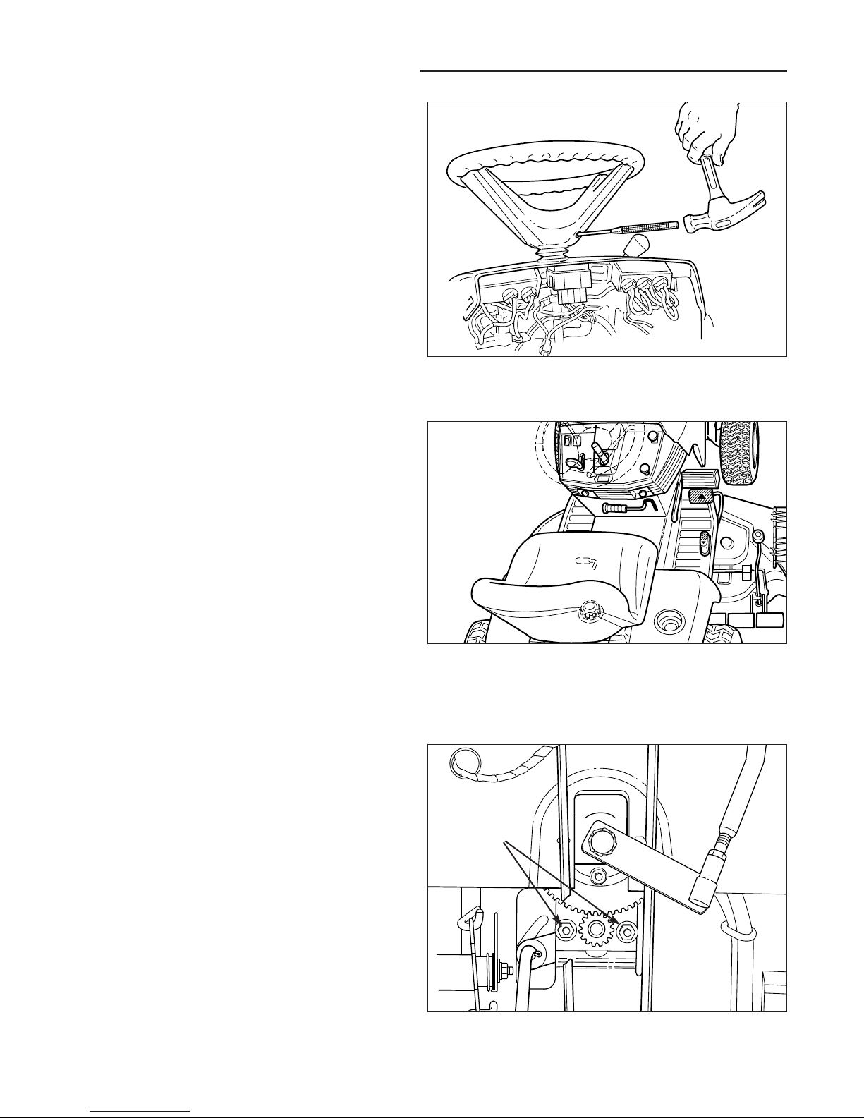
STEERING WHEEL ADJUSTMENT
1. Use a suitable drift to remove the roll pin at the base
of the steering wheel (see Figure 32).
2. Pull down on the rubber boot to expose the two holes
in the steering shaft.
3. Align the hole in the steering wheel with the appropriate steering shaft hole and install the roll pin.
NOTE: Steering wheel is factory installed with the roll pin
in the bottom hole.
Figure 32. Steering Wheel Removal
STEERING GEAR ADJUSTMENT
If there is excessive slack in the steering system, the
steering gear backlash can be removed.
1. See Figure 34. Loosen the two nuts and adjust the
bracket so the gear teeth are closely meshed.
2. Tighten nuts after adjustment.
Figure 34. Steering Gear Adjustment
Nuts
SEAT ADJUSTMENT
See Figure 33. The seat can be adjusted forward and
back. Move the lever, position the seat as desired, and
release the lever to lock the seat into position.
Figure 33. Seat Adjustment
Page 27
25
Troubleshooting, Adjustment, & Service
WARNING
To avoid serious injury, perform adjustments only
with engine stopped, key removed and tractor on
level ground.
Electric PTO Clutch Adjustment
Check the PTO clutch adjustment after the initial 50 hour
break-in period and then after every 250 hours of operation. Perform the following procedure if the clutch is slipping or will not engage. Also perform this adjustment on
new clutches.
1. Remove key from ignition switch and disconnect
spark plug wires to prevent the possibility of accidental starting while the PTO is being adjusted.
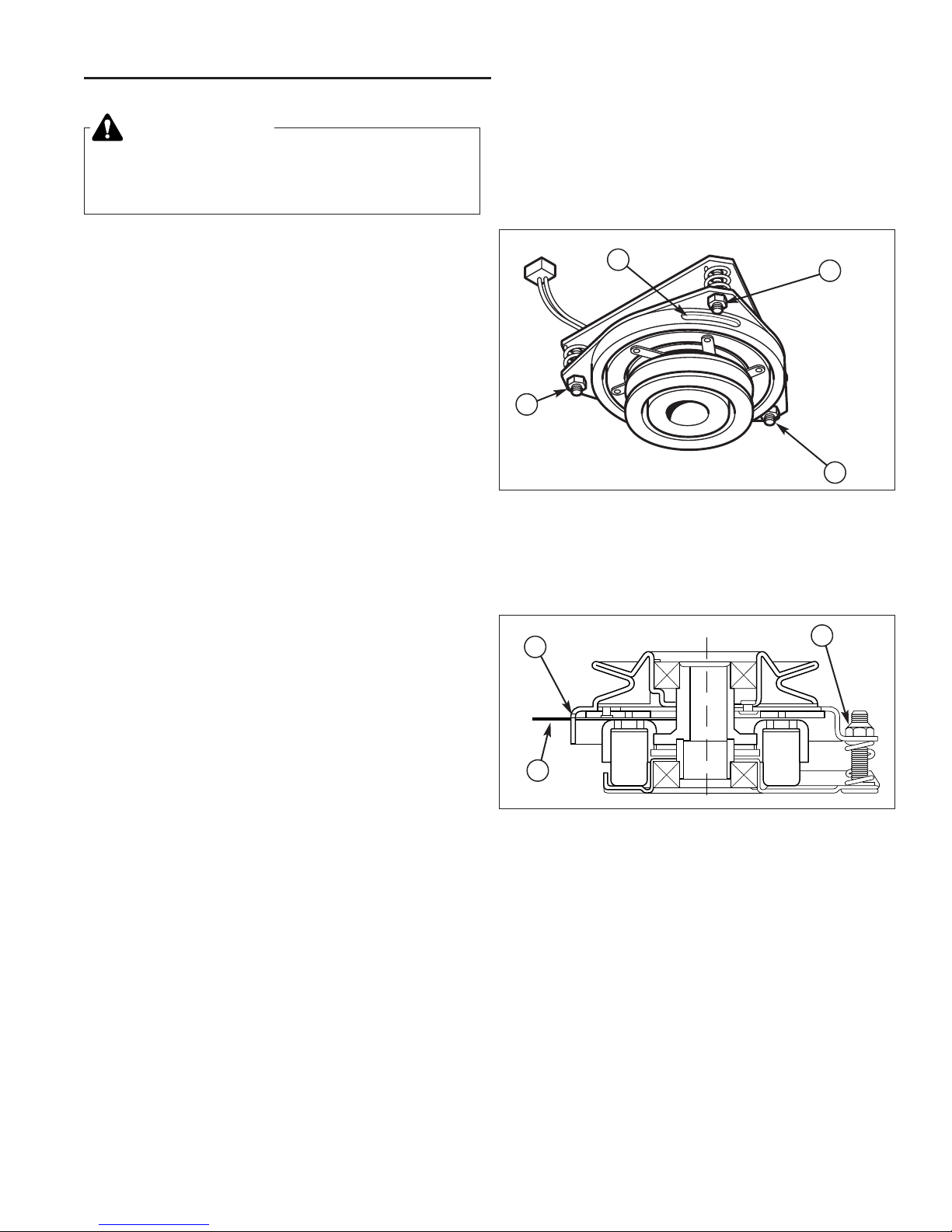
2. Note the position of the 3 adjustment windows (A,
Figure 35 & 36) in the side of the brake plate and the
nylock adjustment nuts (B).
3. Insert a .3mm (.010”) feeler gauge (C, Figure 36)
through each window, positioning the gauge between
the rotor face and the armature face as shown.
NOTE: The air gap must be no less than .010” (.3mm)
and no more than .015” (.4mm).
4. Alternately tighten the adjustment nuts (B) until the
rotor face and armature face just contacts the gauge.
5. Check the windows for an equal amount of tension
when the gauge is inserted and removed, and make
any necessary adjustments by tightening or loosening
the adjustment nuts.
NOTE: The actual air gap between the rotor and armature may vary even after performing the adjustment procedure. This is due to dimensional variations on component parts, and is an acceptable condition.
6. Check the mower blade stopping time. The mower
blades and mower drive belt should come to a complete stop within five seconds after the electric PTO
switch is turned off.
A
B
B
A
B
B
C
Figure 35. Adjust PTO Clutch
A. Window
B. Adjustment Nut
Figure 36. Adjust PTO Clutch
A. Window
B. Adjustment Nut
C. .010” Feeler Gauge
Page 28
26
Troubleshooting, Adjustment, & Service
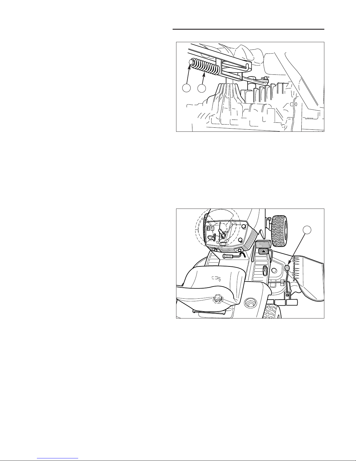
BRAKE ADJUSTMENT
1. Disengage the PTO, stop the engine, block the
wheels, and remove the ignition key. DO NOT
engage the parking brake.
2. Remove the mower deck (see Mower Deck
Removal).
3. Locate the brake spring (A, Figure 37) and adjustment nut (B).
4. With the parking brake disengaged check the brake
spring (A) for movement.
There should be no more that .002” clearance
between the spring (A) and the adjustment nut
(B)–however, spring must NOT be compressed.
If this adjustment does not correct a braking
problem, see your dealer.
Figure 37. Brake Adjustment Nut
A. Brake Spring B. Adjustment Nut
MOWER ADJUSTMENTS
Cutting Height Adjustment
The cutting height adjustment knob (A, Figure 38) controls the mower cutting height. The cutting height is infinitely adjustable between 1” and 3-5/8.” Turn the knob
clockwise to raise the deck and counterclockwise to
lower it.
Figure 38. Mower Cutting Height Adjustment
A. Adjustment Knob
A
B
A
Page 29

27
Leveling The Mower
If the cut is uneven, the mower may need leveling.
Unequal or improper tire pressure may also cause an
uneven cut. Make sure tire pressure is correct as specified in Checking Tire Pressure.
1. With the mower installed, place the tractor on a
smooth, level surface such as a concrete floor. Turn
the front wheels straight forward.
2. Check for bent blades and replace if necessary.
3. Disengage the PTO. Place the mower in mid-cut
position. Arrange the mower blades so that they are
pointing from side-to-side.
4. Measure the distance between the outside tips of
each blade and the ground. If there is more than 1/8”
(3mm) difference between the measurements on
each side, proceed to step 5. If the difference is 1/8”
(3mm) or less, proceed to step 6.
5. See Figure 39. Loosen the outside nut (A). Turn the
eccentric nut (B) to raise or lower left-hand side of
mower. When mower is level, hold the eccentric nut
while tightening the outside nut.
NOTE: When using a turbo collection system, raise the
discharge side of the mower approximately 1/4” to compensate for turbo assembly weight. Check the level of
the cut grass and adjust the 1/4” measurement as necessary for a smooth, even cut.
6. Arrange the blades so they face front-to-back.
7. On 38" deck, measure the distance from the ground
to front tip and rear tip of the left and right-hand
blades.
On 44" and 50” decks, measure the distance from the
ground to the front tip of the center blade, and from
the ground to rear tip of left-hand blade.
Front tips on all decks should be 1/8”-1/4” higher. If
not, proceed with steps 8 - 10.
8. See Figure 40. To raise front of mower deck, loosen
front nut (A) and turn rear nut (B) against bracket (C).
9. To lower front of mower deck, loosen rear nut (B) and
bracket (C) will move backwards to lengthen rod.
10. Re-check measurement before tightening front nut
(A) against bracket.
Troubleshooting, Adjustment, & Service
WARNING
Before checking mower, shut off PTO and engine.
Allow all moving parts to stop. Remove ignition
key, then disconnect the spark plug wire and
fasten it away from the spark plug.
Figure 39. Leveling The Mower Side-to-Side
A. Outside Nut B. Eccentric Nut
Figure 40. Leveling The Mower Front-To-Back
A. Front Nut C. Mower Bracket
B. Rear Nut D. Adjustment Rod
A
B
B
C
A
D
Page 30

28
Troubleshooting, Adjustment, & Service
Figure 41. Transmission Drive Belt Replacement
A. Idler Assy. Spring D. Idler Pulleys
B. PTO Clutch Plug E. Steering Arm
C. Crankshaft Bolt F. Brake Rod
A
F
E
D
B
C
Figure 42. Brake Rod
A. Brake Rod C. Cotter Pin
B. Brake Lever
TRANSMISSION DRIVE BELT
REPLACEMENT
NOTE: Be sure to use only genuine Simplicity replacement parts. Check the back of this manual or the decal
under the hood for common replacement part numbers.
REMOVE THE OLD BELT
See Figure 41.
1. Turn off the PTO, stop the engine, and block the tires.
DO NOT engage the parking brake.
2. Remove the mower deck. See Removing the Mower
Deck.
3. Disconnect the idler pulley assembly spring (A).
4. Unplug the PTO clutch plug (B).
5. Remove the crankshaft bolt (C) securing the PTO
clutch to the crankshaft.
6. Remove the PTO clutch.
7. Disconnect the steering arm (E).
8. Loosen the idler pulleys (D) and remove the belt from
the idler assembly.
9. Remove the belt from the engine drive pulley.
10. See Figure 42. Disconnect the brake rod (A) from the
brake lever (B) at the back of the transmission.
11. Rotate the belt through the blades of the input pulley
fan and remove the belt from the tractor.
INSTALL THE NEW BELT
12. Rotate the belt through the blades of the input pulley
fan and install onto input pulley.
13. See Figure 42. Reattach the brake rod (A) to the
brake lever (B) at the back of the transmission.
14. See Figure 41. Install the belt onto the idler pulleys
(D) and tighten the idler pulley hardware.
15. Install the belt onto the engine pulley.
16. See Figure 41. Reconnect the steering arm (E).
17. Reinstall the PTO clutch. Torque the crankshaft bolt
(C) to 45-50 ft. lbs.
18. Reconnect the PTO clutch plug (C, Figure 41).
19. Reattach the idler assembly spring (A, Figure 41).
A
B
C
Page 31

29
Troubleshooting, Adjustment, & Service
MOWER BELT REPLACEMENT
38” Mower Drive Belt Replacement
NOTE: Be sure to use only genuine Simplicity replacement parts. Check the back of this manual or the decal
under the hood for common replacement part numbers.
NOTE: It is not necessary to remove the mower to install
a new belt. However, for easier access mower can be
removed. See Mower Removal in the Operation section.
Refer to Figure 43.
1. Park the tractor on a smooth, level surface such as a
concrete floor. Disengage the PTO, turn off the
engine and lock the parking brake. Remove the key.
2. If mower is not removed, lower the mower lift and
place the mower in the lowest cutting position.
3. Push the idler arm (A) away from you to relieve belt
tension. Drop the belt from the PTO (electric clutch)
pulley.
IMPORTANT: Note the position of all belt guides relative
to the belt and pulleys before loosening.
4. Loosen the two belt stop brackets (C) and idler pulley
belt guide (D).
5. Remove the old belt and replace with a new belt.
Make sure V-side of belt runs in arbor pulley grooves
and the flat backside runs against the idler pulley.
6. Position the belt stop brackets(C) in their original
positions. There must be 1/8” clearance between the
belt stop and the pulleys.
7. Position the idler pulley belt guide (D) in its original
position up against arm (A) so that there is a 1/8" gap
between the pulley and belt guide.
8. Install mower on tractor if it was removed. See
Operation section.
9. Run the mower under no-load condition for about 5
minutes.
Figure 43. Mower Belt Routing - 38" Mower Deck
A. Idler Pulley Arm C. Belt Stop Bracket
B. PTO Pulley D. Idler Pulley Belt Guide
To avoid damaging belts, DO NOT PRY
BELTS OVER PULLEYS.
C
D
A
C
B
Left Side of Mower
1/8” Gap
1/8” Gap
1/8” Gap
Page 32

30
Troubleshooting, Adjustment, & Service
To avoid damaging belts, DO NOT PRY
BELTS OVER PULLEYS.
44” & 50” PTO Belt Replacement
NOTE: Be sure to use only genuine Simplicity replacement parts. Check the back of this manual or the decal
under the hood for common replacement part numbers.
NOTE: It is not necessary to remove the mower to install
a new belt. However, for easier access mower can be
removed. See Mower Removal in the Operation section.
1. Park the tractor on a smooth, level surface such as a
concrete floor. Disengage the PTO, turn off the
engine and lock the parking brake. Remove the key.
2. If mower is not removed, place the mower in the lowest cutting position.
3. Push the idler arm (A, Figure 44) away from you to
relieve belt tension. Drop the belt from the PTO (electric clutch) pulley.
IMPORTANT: Note the position of all belt guides relative
to the belt and pulleys before loosening.
4. Loosen the nut and lockwasher securing idler pulley
belt guide (C, Figure 44).
5. See Figure 45. Remove three capscrews securing
left-hand arbor cover (D).
5. Remove the old belt and replace with a new one.
Make sure the V-side of belt runs in the pulley
grooves.
7. See Figure 44. Position the idler pulley belt stop (C)
in its original position so that there is a 1/8" gap
between the pulley and belt stop.
8. See Figure 45. Reinstall the left-hand arbor cover
(D).
9. Install mower on tractor if it was removed. See
Operation section, Mower Installation. Install belt to
PTO pulley.
10. Run the mower under no-load condition for about 5
minutes.
Figure 45. Mower Deck - 44" & 50”
A. Upstop
B. Right-hand Arbor Cover
C. Spring
D. Left-hand Arbor Cover
E. Capscrew
Figure 44. Mower Belt Routing - 44" & 50” Mower Deck
A. Idler Pulley Arm C. Idler Pulley Belt Guide
B. PTO Clutch Pulley D. Arbor Drive Pulley
1/8” Gap
FRONT
A
D
A
D
E
C
B
B
C
Page 33

31
Troubleshooting, Adjustment, & Service
44” & 50” Arbor Drive Belt Replacement
NOTE: Be sure to use only genuine Simplicity replacement parts. Check the back of this manual or the decal
under the hood for common replacement part numbers.
1. Park the tractor on a smooth, level surface such as a
concrete floor. Disengage the PTO, turn off the
engine and lock the parking brake. Remove the key.
2. Remove the mower from the tractor. See Mower
Removal in the Operation section.
3. See Figure 46. Remove the two capscrews securing
upstop (A) and remove the upstop.
4. Remove the four capscrews securing the right-hand
arbor cover (B, Figure 46). Remove three capscrews
securing left-hand arbor cover (D).
5. Using a pair of locking pliers or a spring puller,
remove the idler pulley spring (C, Figure 46) from slot
in deck.
6. Loosen capscrew (E, Figure 46) securing the idler
pulley to the bracket. The belt can now be slipped
between the pulley and idler bracket hub.
7. Install a new belt as shown in Figure 47. Make sure
that V-side of belt runs in arbor pulley (A) grooves
and flat side of belt runs against idler pulley (B).
8. Tighten the capscrew (E, Figure 46).
9. Reinstall spring (C, Figure 46) into its slot in mower
deck.
11. Reinstall the left and right arbor covers (B and D,
Figure 46) and upstop (A) using the original hardware.
12. Install the mower onto the tractor.
FRONT
Figure 47. Mower Deck Drive Belt Routing
- 44" & 50” Deck
A. Arbor Drive Pulley (V-sided)
B. Idler Pulley (Flat-sided)
A
A
A
B
Figure 46. Mower Deck - 44" & 50”
A. Upstop
B. Right-hand Arbor Cover
C. Spring
D. Left-hand Arbor Cover
E. Capscrew
A
D
E
C
B
Page 34

32
Troubleshooting, Adjustment, & Service
BATTERY SERVICE
Checking Battery Voltage
A voltmeter can be used to determine condition of battery. When engine is off, the voltmeter shows battery
voltage, which should be 12 volts. When engine is running, the voltmeter shows voltage of charging circuit
which normally is 13 to 14 volts.
A dead battery or one too weak to start the engine may
not mean the battery needs to be replaced. For example,
it may mean that the alternator is not charging the battery properly. If there is any doubt about the cause of the
problem, see your dealer. If you need to replace the battery, follow the steps under Cleaning the Battery &
Cables in the Regular Maintenance Section.
Charging a Completely Discharged Battery
1. Be aware of all the safety precautions you should
observe during the charging operation. If you are
unfamiliar with the use of a battery charger and
hydrometer, have the battery serviced by your dealer.
2. Add water sufficient to cover the plate (fill to the proper level near the end of the charge). If the battery is
extremely cold, allow it to warm before adding water
because the water level will rise as it warms. Also, an
extremely cold battery will not accept a normal
charge until it becomes warm.
3. Always unplug or turn the charger off before attaching or removing the clamp connections.
4. Carefully attach the clamps to the battery in proper
polarity (usually red to [+] positive and black to [-]
negative).
5. While charging, periodically measure the temperature
of the electrolyte. If the temperature exceeds 125° F
(51.6° C), or if violent gassing or spewing of electrolyte occurs, the charging rate must be reduced or
temporarily halted to prevent battery damage.
WARNING
Keep open flames and sparks away from the
battery; the gasses coming from it are highly
explosive. Ventilate the battery well during
charging.
WARNING
Do not attempt to charge a frozen battery. Allow
the battery to warm to 60° F (15.5° C) before
placing on charger.
6. Charge the battery until fully charged (i.e. until the
specific gravity of the electrolyte is 1.250 or higher
and the electrolyte temperature is at least 60° F). The
best method of making certain a battery is fully
charged, but not over charged, is to measure the
specific gravity of a cell once per hour. The battery is
fully charged when the cells are gassing freely at low
charging rate and less than 0.003 change in specific
gravity occurs over a three hour period.
Jump Starting With an
Auxiliary (Booster) Battery
Jump starting is not recommended. However, if it must
be done, follow these directions. Both booster and discharged batteries should be treated carefully when using
jumper cables. Follow the steps below EXACTLY, being
careful not to cause sparks. Refer to Figure 48.
1. Both batteries must be of the same voltage.
2. Position the vehicle with the booster battery adjacent
to the vehicle with the discharged battery so that
booster cables can be connected easily to the batteries in both vehicles. Make certain vehicles do not
touch each other.
3. Wear safety glasses and shield eyes and face from
batteries at all times. Be sure vent caps are tight.
Place damp cloth over vent caps on both batteries.
4. Connect positive (+) cable to positive post of discharged battery (wired to starter or solenoid).
5. Connect the other end of same cable to same post
marked positive (+) on booster battery.
6. Connect the second cable negative (-) to other post
of booster battery.
7. Make final connection on engine block of stalled vehicle away from battery. Do not lean over batteries.
8. Start the engine of the vehicle with the booster battery. Wait a few minutes, then attempt to start the
engine of the vehicle with the discharged battery.
9. If the vehicle does not start after cranking for thirty
seconds, STOP PROCEDURE. More than thirty seconds seldom starts the engine unless some mechanical adjustment is made.
10. After starting, allow the engine to return to idle speed.
Remove the cable connection at the engine or frame.
Then remove the other end of the same cable from
the booster battery.
11. Remove the other cable by disconnecting at the discharged battery first and then disconnect the opposite end from the booster battery.
12. Discard the damp cloths that were placed over the
battery vent caps.
Page 35

33
Troubleshooting, Adjustment, & Service
WARNING
Any procedure other than the preceding could
result in:
(1) personal injury caused by electrolyte
squirting out the battery vents,
(2) personal injury or property damage due to
battery explosion,
(3) damage to the charging system of the
booster vehicle or of the immobilized
vehicle.
Do not attempt to jump start a vehicle having a
frozen battery because the battery may rupture or
explode. If a frozen battery is suspected, examine
all fill vents on the battery. If ice can be seen or if
the electrolyte fluid cannot be seen, do not
attempt to start with jumper cables as long as the
battery remains frozen.
WARNING
For your personal safety, use extreme care when
jump starting. Never expose battery to open flame
or electric spark – battery action generates
hydrogen gas which is flammable and explosive.
Do not allow battery acid to contact skin, eyes,
fabrics, or painted surfaces. Batteries contain a
sulfuric acid solution which can cause serious
personal injury or property damage.
When removing or installing battery cables, disconnect the negative cable FIRST and reconnect
it LAST. If not done in this order, the positive terminal can be shorted to the frame by a tool.
To avoid engine damage, do not disconnect battery while engine is running. Be sure terminal
connections are tight before starting.
Figure 48. Battery Jump Starting Diagram
To
Starter
Switch
Starting
Vehicle
Battery
To Ground
To
Starter
Switch
Discharged
Vehicle
Battery
Engine
Block
THIS HOOK-UP FOR NEGATIVE GROUND VEHICLES
MAKE CERTAIN VEHICLES DO NOT TOUCH
Jumper Cable
Jumper Cable
Page 36

34
Troubleshooting, Adjustment, & Service
HEADLIGHT REPLACEMENT
See Figure 49.
1. Open the hood.
2. Remove the light bulb socket from the bezel by twisting it counterclockwise and pulling it out.
3. Remove and replace the light bulb with an identical
bulb.
4. Reinstall the socket into the bezel.
DASHLIGHT REPLACEMENT
See Figure 50.
1. Open the hood.
2. Twist the socket (A) counterclockwise and pull out to
remove it from the back of the dashboard display (B).
3. Remove and replace the old bulb with a new identical
bulb.
4. Reinstall the socket into the dashboard display.
TRANSMISSION PURGING
Purge the transmission if the unit is excessively noisy or
lacks drive in forward or reverse.
1. Elevate the rear end of the tractor using a chain hoist
or floor jack. Support the rear of the unit using jackstands. Elevate the unit just high enough for the rear
wheels to clear the ground.
2. Activate the seat switch, depress the clutch / brake
pedal, and start the engine. After the engine has
started, set throttle to IDLE.
3. Release the brake pedal and fully depress the forward ground speed pedal.
4. While holding the ground speed control in forward
position, engage and disengage the transmission
release valve lever (A, Figure 51) several times.
5. Fully depress the reverse ground speed pedal.
6. While holding the ground speed control in reverse,
engage and disengage the transmission release
valve lever (A) several times.
7. Engage the transmission release valve lever and
stroke the transmission from full forward to full
reverse several times.
8. Lower the tractor and test run for several minutes.
Figure 49. Headlight Replacement
Figure 50. Dashlight Replacement
A. Dashlight Socket B. Dashboard Display
B
A
Figure 51. Transmission Release Lever
A. Release Lever (Engaged Position Shown)
A
Page 37

35
Specifications
ENGINE
14 HP & 16 HP Briggs & Stratton Vanguard
Make Briggs & Stratton
Model Vanguard™ V-Twin
Horsepower 16 HP @ 3600 rpm
Displacement 29.3 Cu. in (480 cc)
Electrical System 12 Volt, 16 amp Alternator, Battery: 340 CCA
Oil Capacity 56 Oz. w/Filter (1.7 L)
16 HP Briggs & Stratton V-Twin
Make Briggs & Stratton
Model Intek™ V-Twin
Horsepower 16 HP @ 3400 rpm
Cylinder 2
Displacement 40.0 Cu. in (656 cc)
Electrical System 12 Volt, 9 amp Alternator, Battery: 340 CCA
Oil Capacity 4 Pints w/Filter (1.9 L)
18 HP Briggs & Stratton Vanguard
Make Briggs & Stratton
Model Vanguard™ V-Twin
Horsepower 18 HP @ 3600 rpm
Displacement 38 Cu. in (624 cc)
Electrical System 12 Volt, 16 amp Alternator, Battery 340 CCA
Oil Capacity 2 Quarts w/Filter (1.9 L)
16 HP Kohler
Make Kohler
Model Command™ CV16S
Horsepower 16 HP @ 3600 rpm
Displacement 26.0 Cu. in (426 cc)
Electrical System 12 Volt, 15 amp Alternator, Battery: 340 CCA
Oil Capacity 2 Quarts w/Filter (1.9 L)
TRANSMISSION:
Type Tuff Torq K61 Hydrostatic
Hydraulic Fluid 10w 30 Premium Engine Oil
Speeds Forward: 0 - 5.6 MPH (0 - 9.0 km/h)
@ 3400 rpm Reverse: 0 - 3.2 MPH (0 - 4.8 km/h)
Differential Bevel Gear with Controlled Traction
Continuous Torque 188 ft. lbs.
Output
Drawbar Rating 251 lbs.
Maximum Weight 629 lbs.
on Axle
CHASSIS:
Rear Wheels Tire Size: 20 x 10.00-8 Turf Type
Pneumatic Inflation Pressure: 6-8 psi
(41-55 kPa)
Front Wheels Tire Size: 15 x 6.00-6
Pneumatic Inflation Pressure: 12-15 psi
(82-103 kPa)
Fuel Tank Capacity 4 Gallons (15.1 L)
DIMENSIONS:
Overall Length 70.25 in (178 cm)
Overall Width 35 in (88.9 cm)
Height To Top of Steering Wheel: 40 in (101.6 cm)
To Top of Engine Cover: 34 in (86.7 cm)
Wheel Base 50.75 in (129 cm)
Weight (apx..) Net: 424 lbs. (192 kg) w/o mower
536 lbs. (243 kg) w/mower
NOTE: Specifications are correct at time of printing and are subject to change without notice.
Page 38

36
Replacement Parts
Replacement Parts
Replacement parts are available from your authorized dealer.
Always use genuine Simplicity Service Parts.
Snowthrower Cab
42” & 36” Single Stage
Snowthrowers
42" Dozer/Snow Blade
Rear Wheel Weights
Tire Chains
Turbo Twin Bag
Grass Catcher
Dump Cart
Dozer Blade
Gas Cans
Engine Oil
Touch-Up Paint
Grease Gun Kit
8 oz. Grease Tube
Tire Sealant
Degrimer/Degreaser
Gas Stabilizer
Optional Accessories
Maintenance Items
Many convenient and helpful service and maintenance items
are available from you authorized dealer. Some of these items
include:
Page 39

Page 40

MANUFACTURING, INC.
500 N Spring Street / PO Box 997
Port Washington, WI 53074-0997
www.simplicitymfg.com
© Copyright 2001 Simplicity Manufacturing, Inc.
All Rights Reserved. Printed in USA.
 Loading...