

Page 1
SIMPLICITY MANUFACTURING COMPANY.
IN
SNO-AWAY
Page 2
PACKING
The 4 and 6 H.P.
are delivered
complete in their separate cartons. The carton contains:
2
1
Frame, Rotor, Engine and Wheel Assembly
Assembly
1
Spout Adjusting Rod
2
Skid Shoes
1
Bag of Hardware
Should shortages of any of the above items
occur, advise by stating packers number listed on
the green packing slip,.sarial number of Sno-Away,
part number and description of items missing.
ASSEMBLY
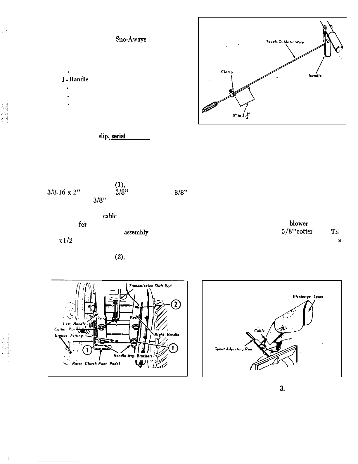
1. Fasten the handle assembly to the mount-
ing brackets as shown at
Figure 1, using the (4)
2’: capscrews, 3/8” plain washers, 3/8”
lockwashers and
hex nuts.
2. The throttle cable assembly is coiled around
the engine
shipping purposes. Uncoil the cable
and attach ‘to the housing
using the (2)
32”
self-tapping screws. The cable is held in
place by the clamp on the lower portion of the
right handle as shown at
Figure 1.
Figure 1.
Figure 2.
3. Insert the lower end of transmission shift
rod through the hole in the shift lever and fasten in
place with a cotter pin as shown in Figure 1.
4. Insert the Touch-0-Matic extension wire
through the wire clamp. For proper belt tension,
adjust as shown in Figure 2.
5. Attach the spout control cable as shown in
Figure 3. Insert the lower end of the spout control
rod in the nylon bearing on the ,blower housing and
hold in place with (2)3/32x 5/8”cotter pins.
spout control rod support bracket is mounted in
reverse position for shipping purposes. Detach and
mount as shown in Figure 4. Tighten clamp as nec-
essary to hold spout in desired position.
Figure
Page 3
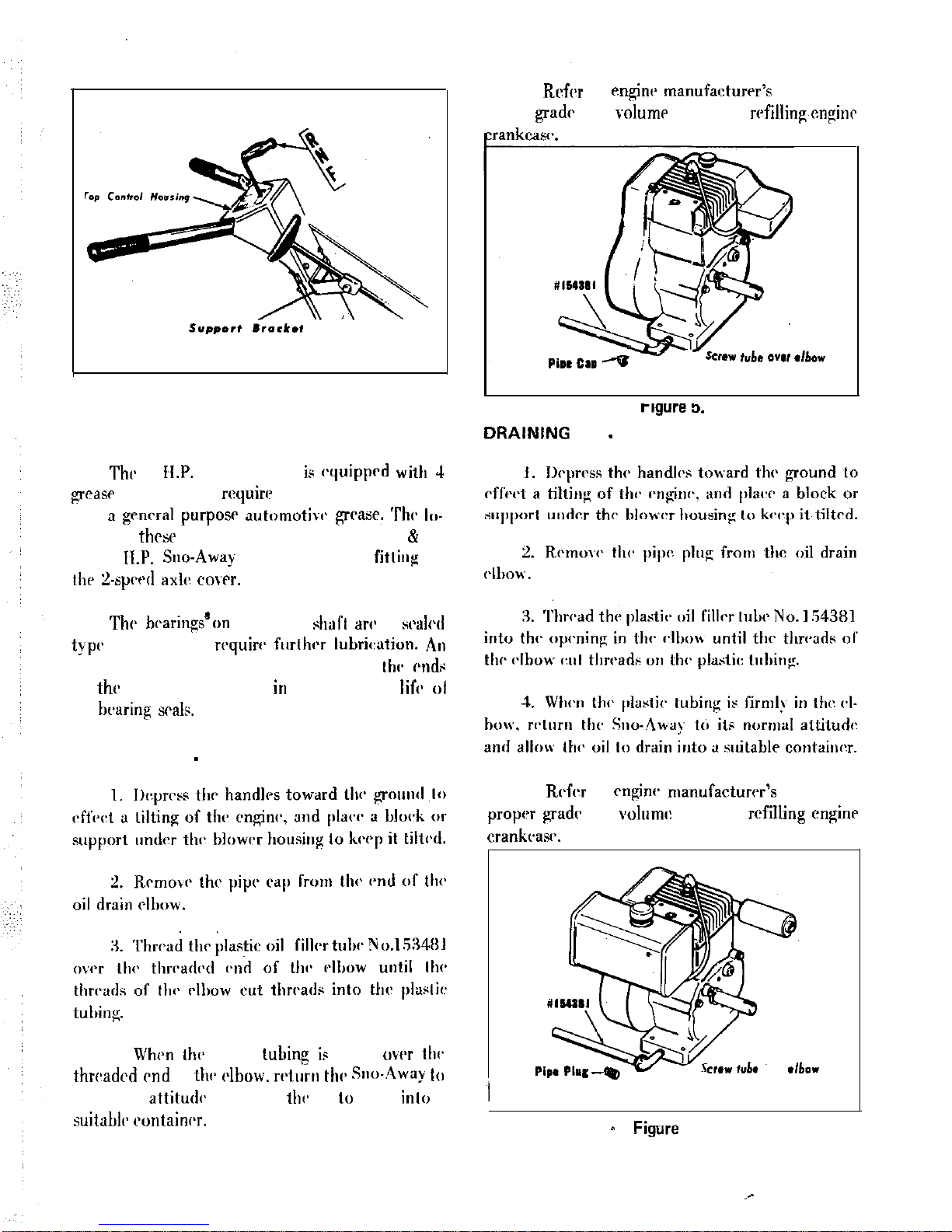
Figure 4.
4 H.P. SNO-AWAY
LUBRICATION
6 H.P. SNO-AWAY
occasional lubrication
with
gcncral
The
ration of thrse fittings is shown in Figures 1.6
9.
Thr 6
Sue-Away has an additional
on
cowr.
and do not
occasional application of light motor oil to thv cwdr
of
rotor shaft will aid
prolonging thr
ol
thr
DRAINING OIL
4 H.P. SNO-AWAY
5.
and volurm: of oil for
engine
4. When
plastic
is firmly
elbow. wturn thv Stw-.4way
its normal
and allow
oil
drain
a
tub. into
6 H.P. SNO-AWAY
Figure 6.
5. Rrfcr to
manufacturrr’s manual for
proper
of oil for
3
Page 4
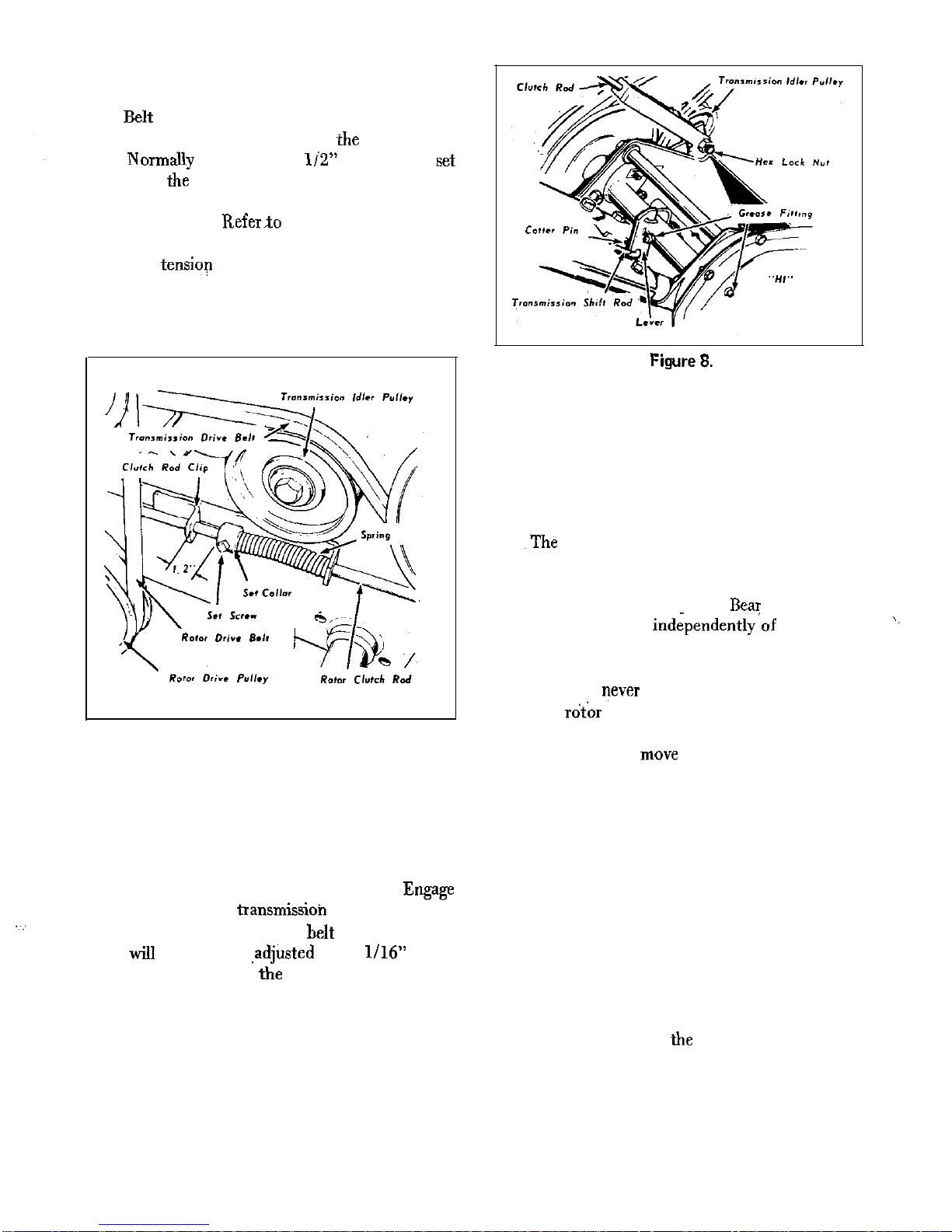
BELT TENSION ADJUSTMENT
the position of the set collar on
rotor clutch
rod. NormaRy
a clearance of 1iZ” between the
collar and
this belt. Check this adjustment when the rotor
clutch is engaged.
Figure 7.
Belt tensiop for transmission drive belt is reg-
ulated by the position of the wire clamp on the ex-
tension spring.
Figure 7.
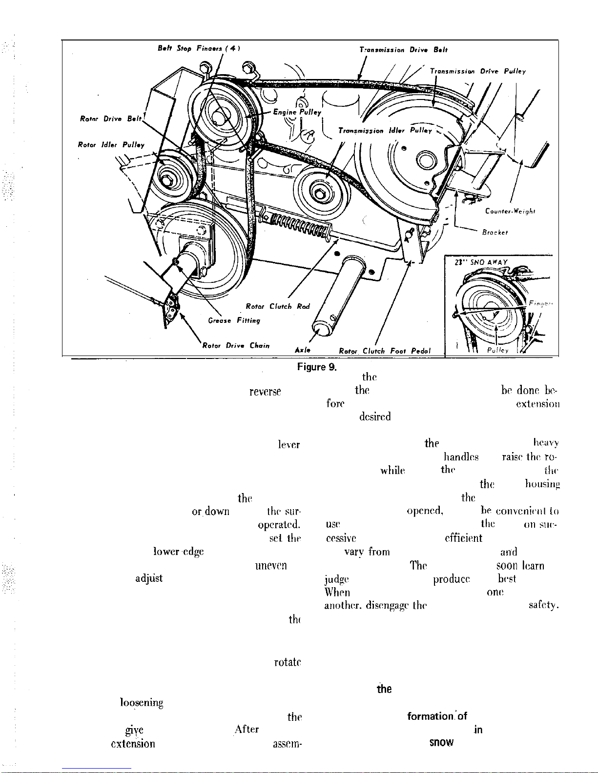
BELT STOPS ADJUSTMENT
On the drive pulley side of the engine, belt
stops arc mounted as shown in Figure 9.
the rotor clutch and
clutch and check
clearance between belts and
stops. The belt
stops
be properly
when
clear-
ance is visible between
stops and the belts. To
adjust, loosen the hex capscrews and reposition the
stops to proper clearance. Retigbten hex capscrews
to hold stops in proper position. Refer to Figure 9.
OPERATION
Before attempting to start the engine or to op-
erate the Sno-Away, refer to the engine manufac-
turer’s owner’s manual for the proper fuel, oil, and
procedure for starting the engine.
operation of the rotor is controlled by the
rotor clutch. To engage the rotor clutch, raise the
foot pedal shown in Figure 9.
To disengage the
clutch, depress the foot pedal.
in mind that
the rotor will operate independently~of the forward
travel of the Sno-Away, as long as the engine is run-
ning and the clutch is engaged. Exercise caution at
all times, and
from the r&or housing or discharge spout unless
the engine is stopped and rotor clutch is disengaged.
To stop the engine,
the throttle control lever
all the way to the shut-off position.
If the engine fails to shut-off after moving the
throttle control lever to the shut-off position, re-
position the “shorting-wire” to make contact with
the ignition shorting lever located on engine at end
of throttle cable.
The direction of travel of the Sno-Away is
controlled by the position of the transmission shift
lever. Refer to Figure 2. When shifting the transmission, always release Touch-0-Matic control.
With the clutch disengaged, push down on the trans-
mission shift lever and
transmission will shift
Page 5
into forward position and Sno-Away will travel forward when the clutch is engaged. To reverse the
Sno-Away, disengage the clutch and pull up on
shift lever and transmission will shift into the reverse position. Neutral position of the shift lever is
half way between forward and reverse and thr
will be held in this position by a detent lever on the
left side of the Sno-Away frame.
The skid shoes on each side of
rotor housing are adjustable either up or.down to suit
face over which the Sno-Away is to be operated.
For smooth surface, loosen the nuts and
shoes so that the lower~edge of the rotor housing
rides near the surface. For use over an unewn or
rough surface
When using the Sno-Away, adjust the discharge
spout so that the snow will be thrown with th(
wind and never into the wind. Throwing snow into
the wind will be a source of discomfort to the operator. To alter the direction of discharge,
the spout by means of the spout adjusting handle.
The distance that the snow may be thrown may be
adjusted by
charge spout extension and raising or lowering.
extension to give the desired angle. ,After adjusting,
push the
snugly against the spout asscm
bly to prevent snow from being blown backwards
against
engine and operator. Slotted holes be-
neath
wing nuts will allow this to
in the dcsircd position,
When operating
Sno-Away through
drifts of snow, depress the handles and
ro-
tor housing
taking
first pass through tiw
drift.
Then back off and lower
rotor housing
and go through again. After
first path through
thr drift has been
it may be
to
only a portion of thr width of
plow on w,--
will
from lo-
cation to location.
operator w-ill soon
to
which mrthods
the
results.
discngagc
rotor clutch for safety.
IMPORTANT
After completion of plowing operation,
allow the engine to operate in a sheltered
area for about 5 minutes to dry itself and
prevent the
sible, store the Sno-Away
a cold area
so that clinging
will not melt and
refreeze into ice.
Page 6

WARRANTY
The company
Simplicity
tc be free
defects in material and
except
the
makes M warranty
or
with respect
tires. engines and engine accessc-
warranted by their respective mamfaoturers. Any part covered by
war-
ranty
is prcvendefmtive
cm year, under
from date of purchase, will be re-
placed free of charge,
Port Washiwtcn, Wisconsin, provided such part is returned
factory
prepaid and is found tc be defective
at the factory. The ccm-
is not obligated
this warranty
bear cost of labor
delivery charges
replacement of
defective parts.
warranty does not apply
any Simplicity Products
outside of Simplicity’s
factory. Such replacement of defective parts shall be tlie exclusive remedy
event shall Sim-
plicity be liable for
damages. EXCEPT AS SPECIFICALLY PROVIDED HEREIN, THERE
ARE NO WARRANTIES
EXTEND BEYOND THE DESCRIPTION ON ANY SIMPLICITY PRODUCT.
SAFE SNOW REMOVAL IS NO ACCIDENT
Page 7

SPOUT GROUP
106785
H
720001
717001
K
106881
L
106491
705015
N
720003
Q
106870
R
106516
S
715067
T 722016
V
121175
w
705018
X
717511
Z 705053
AA
720003
AB
AC
106867
AD
722015
AE
DESCRIPTION
21"
106762 Spout Assembly
703005
Bolt, 5/16
18
3/4”
106760
Spout Extension
719001
Plain Washer,
721601
Lock Washer,
106229
Wing Nut
106785
Cup Washer
717001
106881
106491
705015
720003
717005
106870
106516
715067
722016
152050
121175
705018
717511
705053
720003
717005
106867
722015
106512
Lock Washer, 5116
Hex Nut,
5/16
18
Cable
Bearing
Hex
5/B”
Washer,
Hex Nut,
20
Spout Control, Tube Assembly
Handle Cover
Self-Tapping Screw, 20
3/B” lg.
Rod Guide
Guide
Hex
5/16
18
1.112”
Hex Nut, Full, Lock,
18
Spout Adjusting Rod Support
Hex Capsqw, 114
20
Lock Washer,
Hex Nut,
20
1”
Page 8

ROTOR BODY and FRAME
1
Page 9

ROTOR BODY and FRAME
REF. PART NUMBER
DESCRIPTION
LET. 26”
21”
A
106832 106814
IO6745 106745
Scraper
Body
715071 715071
Capscrew, S/16
lg.
Nut Fult Lock, 5116. 18
F
20
5/E-‘lg.
Lock Washer,
II
71700s 717005
20
Skid
Ii 7n3004 703004 Carriage Bolt,
16
lg.
I,
Plain Washer,
720002 720002
Lock Washer, 3/B”
Nut Full, 3/B I6
I’
Rotor Assmbly
106732 106732
Screw,
28
lg.
1
18
314”Ig.
I
720001 720001 Lock
5116”
\ 717001 717001
\\ IO6633 IO6653 Rotor Sprocket
S/16” lg.
I .i
IO6376
106176
Clamp Support Assembly
Caprcrw. 3/E 16
1”
‘JO0 I
Plain
3/R”
71000’ Lark Washer, 3/B”
I 7003
7003 ttrx Nut Full. 3/B 16
106771 Stud
I1tm.i
Nut. “Whiz Lock”. 3/8 16
in.50
l-1/2” lg.
I
Ii
I
I
727002
11061012 tw6
IO I
I
D6750 Chain Guard
720002
720002 Lock Washvr. 3/B”
7003
Nut Full.
I6
I
n
Scww 5/16 18
lg.
10677-L
2 705012
Crpwnw. 5/16 I8
S/B”
II:\
5/16”
700
Nlll Pull. 5/16
w,tf,
I l100l1 7 I
Page 10

HANDLES
CONTROLS
106546
i
10
Page 11

REF.
LET.
A
C
D
E
F
G
K
L
N
P
Q
R
S
T
U
V
W
X
Y
Z
AB
AC
AD
A!?.
AF
AG
AH
AK
AL
AM
AN
AP
AR
As
AT
AU
AV
AW
HANDLES & CONTROLS
PART
26”
21”
106781 106781
106782 106782
106558 106558
705006 705006
720002
720002
717003 717003
705025 705025
720003 720003
717005 717005
106780 106780
106524 106524
714003 714003
718019 718019
106563 106563
714005 714005
106564 106564
106778 106778
717003 717003
154534 154534
717524 717524
705010 705010
717510 717510
106776 106776
722001 722001
106572 106572
106201 106201
8171073 8171073
705010 705010
154534 154534
106829 106829
8191045 8191045
8191022 8191022
713001 713001
705031 705031
106223 106223
717003 717003
108418 108418
106204 106204
717513 717513
118056 118056
106786 106786
8081503 8081503
8161215 8161215,
DESCRIPTION
Handle, LH
Handle, RH
Grip
Hex Capscrew, 3/8
16
2”
Plain Washer,
Lock Washer,
Hex Nut,
16
Handle Cover
Hex Capscrew, 20
Lock Washer,
Hex Nut,
20
Housing Assembly
Support, Throttle Control
Hex Screw, self-tap. No.10 32
Speed Nut, Tinnerman
Throttle Control Assembly
Screw, self-tap. No.10 -24
Lever Pin
Spring Assembly
Hex Nut,
16
Idler Pulley (Trans. Drive)
Hex Jam Nut
Hex Capscrew, 3/8”- 16
314”
Hex Nut,
Lock,
16
Reverse Rod
Cotter Pin, 3132”
314”
Grip, Reverse Rod
Idler Lever Assembly
Bearing Race, Inner
Hex Capscrew, 3/8 16
l-3/4
Idler Pulley (Rotor Drive)
Rotor Clutch Rod
Spring
set Collar
Set Screw, Sq. Hd. 20
3/8
Hex Capscrew, 3/8
16
lg.
Foot Clutch
Hex Nut, Full,
16
Special Capscrew
Idler Lever Assembly
Hex Nut, Full, Lock,
20
Clutch Grip
Clip
Clutch Rod Guide Assembly
Bushing
11
Page 12

Page 13

C
D
F
J
L
N
S
T
u
v
x
J
26”
______
153089
727002
061046
713006
153114
153105
705012
720001
7 1700 1
106193
12 1044
705005
719001
720002
7 17003
153124
153079
121306
153078
106199
727002
051038
121115
153079
153124
121118
121163
121139
153094
719002
7 15033
153090
153115
153106
714006
716008
106215
106217
106216
720001
7 1700 1
718021
7 140 14
719006
TRANSMISSION, WHEELS
*my
106777 Guide, Clutch Wire
only)
153069 Bearing
727002 Grease Fitting
106435 Axle
061046 Set Collar
713006 Set Screw,
153 114 Gasket, Bearing Hous,ing
153 105 Gear Case
705012 Hex
x
720001 Lock Washer,
106193 Shaft, Intermediate
12 1044 Lock Pin.
705005 Hex Capscrew, 3/S”-16 x 1”
719001
Washer,
720002 Lock Washer,
717003 Hex Nut, Full,
153124 Retaining Ring
153079 Washer
12 130 6
Gear Assembly, Internwdfate
153078 Bearing, Intermediate
106199 HousIng Assembly, Bearing
727002 Grease Fitting
051038 Bearing
121115 Pulley Shaft Assembly
153079 Washer
153124
12 1118 Reverse
12 1
121163 Pinion Spacer
121139 Lock Plate
1530 94 Shield
719002
Washer,
715033 Hex Head Bolt, L.H.
153090 Nut, Hex, Full, L.H.
153115 Gear Case Gasket
153106 Gear Case Cover Assembly
714006 screw.
x
718008 Speed Nut
106215 Plate, Friction, Stop
1062 17 Spacer, Frame
106216 Bolt, Frame
720001 Washer, Lock,
717001 Hex Nut, Full,
718021 Detent, Neutral
7 14014 Screw,
3,
719006 Washer, Plain,
26” 21”
,
x 5/S
CA 153121 153121 Spring, Reverse Lever
CB 153011 153011 Extension,
cc
------ Sun Gear Assembly
CD 121167 ------ snap Ring
CE
106394 ------ Key
CF 106410 ------ Shift Rod Assembly
CG 121169 ------ Shift Block
CH 106572 ------
Rod Grip
720003
Lock Washer,
CL 717005 ------ Hex Nut, Full,
CM 121148 ------ Cover Assembly
CN 121151 ------ Ring Gear
121118
------ ------
spacer
CR 121162 ------ Bolt Ring
121184 106416
------ ------ Hex Head Bolt
‘Spider
cu 72 1004
Lock Washer,
Shakeproof
cv 718015 ------ Hex Nut, Full,
cx 121186 ------ Seal, Housing Assembly
705015
x 5/a
DA 10639:
WaSher’
DB 106406 ------ Axle Shaft
DC 106405 ------Axle Plate, R.H.
DD 154291 ------ snap Fd.,g
DE 727002 ------ Grease Fitting
DF 7 19002
Plain Washer,
DG 106392 ------ spacer
DH 720002
Lock Washer,
717003
Hex Nut, Full,
DK 153068 ------ Bearings
DL 106414 ------ Gear 6 Tube Assembly
DM 121144 ------ Cover, Gear Case Assembly
DN 715017 ------ Hex
l-l,,
DP 7 19002 ------ Plain Washer,
DR 153074 ------ Guide, Rod
DS 121175 ------ Liner
DT 106419 106419 Wheel
Tire Assembly
DV 8161045 8161045 Spring Clip
DW 106420 106420 Steel Wheels
DX 8061055 6061055 seal. Felt
I
Page 14

SHIELD, DRIVE
PULLEYS, ENGINE
Page 15

A
B
C
D
E
F
G
J
K
L
N
s
T
v
W
X
Y
BB
ac
3D
BE
3F
3G
3H
3J
3K
3L
3M
3N
3P
3R
3s
BT
BV
BW
Bx
BY
CT
SHIELD, DRIVE PULLEYS, ENGINE
106519
106573
705012
720001
7 18030
------
106523
106576
106577
106525
710004
106578
720001
7 17001
------
106520
705007
720001
717001
106579
715037
-----106779
715079
------
7 13504
159129
154307
3021077
106522
8061089
706001
719002
106347
705017
106346
706016
106581
106385
------
------
------
106.585
106586
714003
7 19007
718031
7
106214
718041
725003
154381
728501
------
713503
719002
106582
8081035
154247
21"
106533
106534
705012
-----718030
106372
------
------
------
------
------
------
-----106541
705007
720001
7 1700 1
106537
715037
106540
7 14007
106439
------
715081
106227
713504
154307
8021077
------
------
------
719002
------
------
------
------
------
-----106624
106545
706017
721506
106591
114003
-----718031
718019
106214
718041
725003
154381
728502
106601
726502
106547
713503
------
-----
-----______
Hood Support
18 x 5f8”lg.
Lock Washer,
Speed Clip
Rear Hood Support
Brace . .
Round Hd. Screw, X10-32 x
Bolt, Hood Spacer
Lock Washer,
Hex Nut, Full:
Belt Guard Support
Belt Guard Brace
Hex
18 x
Lock Washer,
Hex Nut, Full,
Belt Guard Assambly:~
Thumb Screw
Belt Guard Bracket
Hex. Hd.,Self-Tapping,
x
16 x 1.114”
Caprew,
16 x 1” lg.
Engine Pulley
Set Screw, Cup
lg.
V-Belt ( Rotor Drive )
V-Belt ( Transmission Drive
Guard Support
Belt Stop
Hex Capscrew,
24
lg.
Washer,
Belt Stop
Hex
x
lg.
Belt Stop
x
lg.
Rubber
Tube Clamp
Belt Stop
x 1” lg.
Washer, Int. Shakeproof,
cover, Air cooling
Cover Bracket
screw,
x10
lg.
Plain Washer,
Speed Nut, Special
Speed Nut
Pulley, Transmission Drive
Nut
Tube, 011 Filler
Street Elbow,
Nipple
cap
Strip. White
screw. set
Plain
Clamp
Capscrew. Self-tapping
Page 16

Figure 10.
COUNTER-WEIGHT KIT
Article No. 260
REF. PART NUMBER
LET. 26’
21”
Sno-Away
DESCRIPTION
1
A
106449
Bracket, Weight
154322
Weight Assembly
C
118053
Pin
Clip, Spring
COUNTER-WEIGHT KIT
Article No. 260
For added traction in extreme icy conditions, and
added handling ease, the above counterweight kit
is available as optional equipment.
The bracket aid weight are attached as shown in
Figure 7.
Order Steel Lug Wheels by Article Number 257.
Order Rubber Tire Wheels by Article Number 258.
Order Tire Chains for Rubber Tire Wheels only, by
Article Number 259.
 Loading...