

Page 1
Parts Manual
1390 Large Frame
Two-Stage Snowthrowers
13HP Snowthrowers
Mfg. No. Description
1694237 1390E, 13HP Snowthrower
1694266 1390M, 13HP Snowthrower (CE)
1694443 1390M, 13HP Snowthrower (CE)
1694444 1390E, 13HP Snowthrower
09/2003
Rev.
TP 400-3532-01-LW-S
Page 2

Page 3

Table Of Content
s
TRACTOR / MOWER DECK COMPONENTS PAGES
Handles and Controls Group .................................................................................................
Handles and Controls Group .................................................................................................
Engine and Frame Group - 13HP, Electric Start ...................................................................
Engine and Frame Group - 13HP, Manual Start ...................................................................
Auger and Impeller Group - 38" .............................................................................................
Auger Housing and Chute Group - 38" ..................................................................................
Traction Drive Group .............................................................................................................
Traction Drive Group .............................................................................................................
Wheels & Tires Group ...........................................................................................................
Decals Group - 1390 ............................................................................................................
Headlight Group ....................................................................................................................
Headlight Group ....................................................................................................................
12
16
20
22
26
30
34
36
38
40
Torque Specification Chart ..................................................................... Inside Back Cover
4
8
Page 4

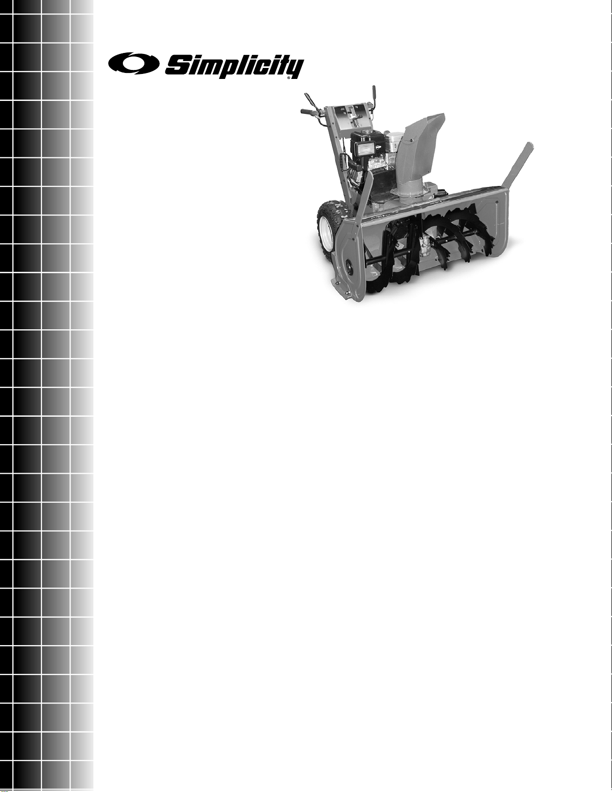
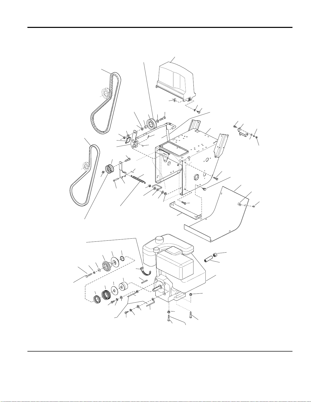
Handles and Controls Group
NOTE: Unless noted otherwise,
use the standard hardware torque
specification chart.
60
59
58
55
61
62
48
4
17
45
56
26
45
27
28
54
51
46
47
53
48
49
52
49
47
50
48
2
1
65
42
63
66
4
42
43
44
Shift rod assembly
(Ref. 54) must pivot
freely on pivot blocks
(Ref. 59).
Mount clutch cable to cable
support, see Engine & Frame.
986156
3
9
37
8
57
38
Torque to
19 - 29 ft-lbs.
10
11
39
To engine
plug
12
13
36
15
14
35
30
To engine
ground
17
18 19
4
24
25
26
27
28
29
16
20
21
22
5
4
96
67
see spout
group
23
31
32
33
41
4
5
7
6
4
40
64
51
Linkage adjustment for traction and auger drive
with power boost: with drive levers engaged, the
bottom end of lower rods (Ref. 33 & 67) should be
flush with bottom of springs (Ref. 32 & 68).
The above parts group applies to the following Mfg. Nos.:
1694237 - 1390E
1694266 - 1390M
© Copyright Simplicity Manufacturing, Inc. All Rights Reserved.
2003
To headlight
4
34
To spout
motor
TP 400-3532-01-LW-S
Page 5

Handles and Controls Group
PART NO. DESCRIPTIONREF NO. QTY.
1 1928732 1 CAPSCREW, Hex Washer Head, #10-24 x 1
2 1612165 1 HANDLE, Clutch, RH
3 1668608 2 GRIP
4 1668185 6 BUSHING, Nylon
5 1704255 2 LEVER & TUBE ASSEMBLY, Clutch
6 1960471 4 CAPSCREW, Hex Washer Head, #12-24 x 1
7 1705899 1 G U I D E , Co n t r ol
8 1723965 2 GRIP, Heated
9 1667800 1 DASHBOARD
10 1935450 4 CAPSCREW, Hex Head, 1/4-20 x 3/4
11 1921221 1 CAPSCREW, Hex Head, 5/16-18 x 1 1/2
12 1678579 1 SPACER
13 1705898 1 LATCH, Control
14 1701342 1 SPRING, Compression
15 1919326 2 WASHER, 5/16
16 1920397 4 NUT, Hex Lock, 1/4-20
17 1923362 1 NUT, Hex, Center Lock, 5/16-18
18 1933896 1 NUT, Hex Lock, #10-24
19 1720747 1 CLAMP, Clutch Cable
20 1723962 1 HANDLE ASSEMBLY
21 1718804 1 TRIGGER ASSEMBLY, Easy Turn Clutch Cable
22 1960393 1 SCREW, Pan Head, Phillips, #10-24 x 1
23 1612167 1 HANDLE, Clutch
24 1925003 4 CAPSCREW, Hex Head, Taptite, 1/4-20 x 1/2
25 1668121 1 ROD
26 928704 2 NUT, LH, Machine Screw, Hex, #10-24
27 108775 2 TURNBUCKLE
28 1916621 2 NUT, RH, Machine Screw, Hex, #1 0-24
29 1707452 1 SPRING
30 1668526 1 ROD, Clutch
31 1724205 1 SWITCH, Rocker, Spout Rotator
32 1723967 1 SWITCH, Hand Warmer, Off, Warm, Hot
33 1724037 1 RESISTOR BLOCK
34 1723968 1 HARNESS Assembly
35 1664022 1 GROMMET
36 1930591 6 CAPSCREW, Hex Whiz Lock, 5/16-18 x 3/4
37 1718791 1 CABLE & HANDLE ASSEMBLY, Clutch (Includes Ref. 21)
38 1931277 6 NUT, Hex Flange, 5/16-18
39 1927429 2 CAPSCREW, Hex Washer Head, 1/4-20 x 5/8
40 1723935 1 BRACKET, Shift Control
Footnotes
The above parts group applies to the following Mfg. Nos.:
1694237 - 1390E
1694266 - 1390M
© Copyright Simplicity Manufacturing, Inc. All Rights Reserved.
2003
5
TP 400-3532-01-LW-S
Page 6
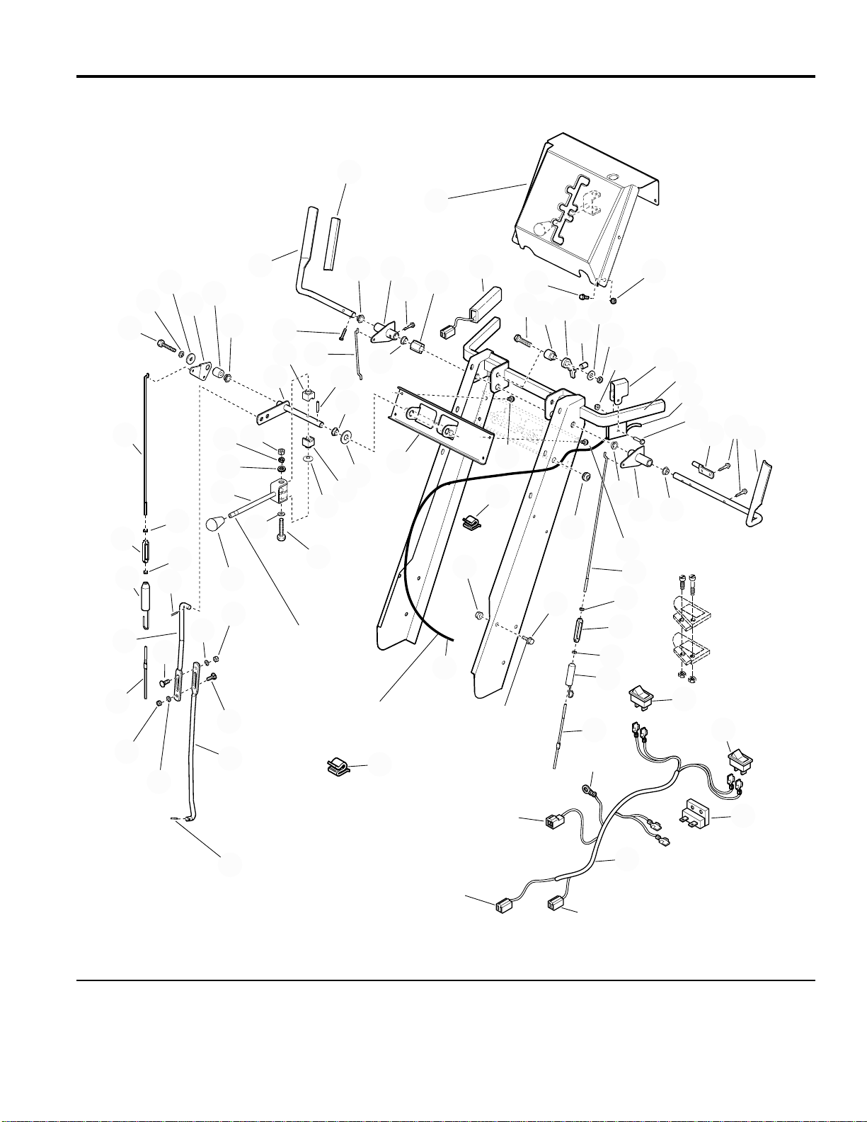
Handles and Controls Group
NOTE: Unless noted otherwise,
use the standard hardware torque
specification chart.
60
59
58
55
61
62
48
4
17
45
56
26
45
27
28
54
51
46
47
53
48
49
52
49
47
50
48
2
1
65
42
63
66
4
42
43
44
Shift rod assembly
(Ref. 54) must pivot
freely on pivot blocks
(Ref. 59).
Mount clutch cable to cable
support, see Engine & Frame.
986156
3
9
37
8
57
38
Torque to
19 - 29 ft-lbs.
10
11
39
To engine
plug
12
13
36
15
14
35
30
To engine
ground
17
18 19
4
24
25
26
27
28
29
16
20
21
22
5
4
96
67
see spout
group
23
31
32
33
41
4
5
7
6
4
40
64
51
Linkage adjustment for traction and auger drive
with power boost: with drive levers engaged, the
bottom end of lower rods (Ref. 33 & 67) should be
flush with bottom of springs (Ref. 32 & 68).
The above parts group applies to the following Mfg. Nos.:
1694237 - 1390E
1694266 - 1390M
© Copyright Simplicity Manufacturing, Inc. All Rights Reserved.
2003
To headlight
6
34
To spout
motor
TP 400-3532-01-LW-S
Page 7

Handles and Controls Group
PART NO. DESCRIPTIONREF NO. QTY.
41 1924361 1 WASHER, 1/2
42 1668524 2 BLOCK, Pivot
43 1668681 1 WASHER, Curved, 1/2
44 1921159 1 CAPSCREW, Hex Head, 1/4-20 x 2 1/4
45 1921319 1 WASHER, 1/4
46 1713844 1 KNOB
47 1916622 2 NUT, Hex, 1/4-20
48 1916964 2 LOCKWASHER, Spring, 1/4
49 1931317 2 CARRIAGE BOLT, 1/4-20 x 3/4
50 1666255 1 ROD, Shift, Lower
51 1918447 3 PIN, Cotter
52 1702004 1 ROD, Clutch, Low e r
53 1720448 1 ROD, Shift, Uppe r
54 1701996 1 SPRING
55 1702485 1 ROD, Clutch, Upper
56 1714120 1 SHIFT ASSEMBLY, Rod & Clevis
57 934683 2 CLIP, Wire
58 1922127 1 CAPSCREW, Hex Head, 5/16-18 x 3/4
59 1917356 1 LOCKWASHER, Spring, 5/16
60 1919381 1 WASHER, 5/16
61 1702662 1 LEVER, Clutch
62 1702552 1 SPACER
63 1703043 1 ROD & ARM ASSEMBLY, Pivot
64 172434 2 CLIP, Wire
65 1702663 1 ROD, Clutch
66 1918452 2 PIN, Cotter
67 1677453 1 ROD, Control
Footnotes
The above parts group applies to the following Mfg. Nos.:
1694237 - 1390E
1694266 - 1390M
© Copyright Simplicity Manufacturing, Inc. All Rights Reserved.
2003
7
TP 400-3532-01-LW-S
Page 8
Handles and Controls Group
NOTE: Unless noted otherwise,
use the standard hardware torque
specification chart.
60
59
58
55
61
62
48
4
17
45
56
26
45
27
28
54
51
46
47
53
48
49
52
49
47
50
48
2
1
65
42
63
66
4
42
43
44
Shift rod assembly
(Ref. 54) must pivot
freely on pivot blocks
(Ref. 59).
Mount clutch cable to cable
support, see Engine & Frame.
986375
68
3
9
22
8
57
38
Torque to
19 - 29 ft-lbs.
10
11
39
To engine
plug
12
13
36
15
14
35
30
To engine
ground
29
17
24
28
27
26
25
20
4
16
18
21
96
67
4
5
23
see Spout
Group
31
32
33
41
4
5
7
6
4
40
37
64
51
Linkage adjustment for traction and auger drive
with power boost: with drive levers engaged, the
bottom end of lower rods (Ref. 33 & 67) should be
flush with bottom of springs (Ref. 32 & 68).
The above parts group applies to the following Mfg. Nos.:
1694444 - 1390E
1694443 - 1390M
© Copyright Simplicity Manufacturing, Inc. All Rights Reserved.
2003
To headlight
8
To spout
motor
34
19
45
16
TP 400-3532-01-LW-S
Page 9

Handles and Controls Group
PART NO. DESCRIPTIONREF NO. QTY.
1 1928732 1 CAPSCREW, Hex Washer Head, #10-24 x 1
2 1612165 1 HANDLE, Clutch, RH
3 1668608 2 GRIP
4 1668185 6 BUSHING, Nylon
5 1725205 2 LEVER & TUBE ASSEMBLY, Clutch
6 1960471 4 CAPSCREW, Hex Washer Head, #12-24 x 1
7 1705899 1 G U I D E , Co n t r ol
8 1723965 2 GRIP, Heated
9 1667800 1 DASHBOARD
10 1935450 4 CAPSCREW, Hex Head, 1/4-20 x 3/4
11 1921221 1 CAPSCREW, Hex Head, 5/16-18 x 1 1/2
12 1678579 1 SPACER
13 1705898 1 LATCH, Control
14 1701342 1 SPRING, Compression
15 1919326 2 WASHER, 5/16
16 1920397 5 NUT, Hex Lock, 1/4-20
17 1923362 1 NUT, Hex, Center Lock, 5/16-18
18 1725702 1 SCREW-PAN HD TORX #10 x 1/2
19 1923341 1 CAPSCREW-HEX HD 1/4-20 x 3/4
20 1725124 1 HANDLE ASSEMBLY
21 1718804 1 TRIGGER ASSEMBLY, Easy Turn Clutch Cable
22 1724096 4 RIVET, Pop
23 1612167 1 HANDLE, Clutch
24 1925003 4 CAPSCREW, Hex Head, Taptite, 1/4-20 x 1/2
25 1668121 1 ROD
26 928704 2 NUT, LH, Machine Screw, Hex, #10-24
27 108775 2 TURNBUCKLE
28 1916621 2 NUT, RH, Machine Screw, Hex, #1 0-24
29 1707452 1 SPRING
30 1668526 1 ROD, Clutch
31 1724205 1 SWITCH, Rocker, Spout Rotator
32 1723967 1 SWITCH, Hand Warmer, Off, Warm, Hot
33 1724037 1 RESISTOR BLOCK
34 1725409 1 HARNESS Assembly
35 1664022 1 GROMMET
36 1930591 6 CAPSCREW, Hex Whiz Lock, 5/16-18 x 3/4
37 1718791 1 CABLE & HANDLE ASSEMBLY, Clutch (Includes Ref. 21)
38 1931277 6 NUT, Hex Flange, 5/16-18
39 1927429 2 CAPSCREW, Hex Washer Head, 1/4-20 x 5/8
40 1723935 1 BRACKET, Shift Control
Footnotes
The above parts group applies to the following Mfg. Nos.:
1694444 - 1390E
1694443 - 1390M
© Copyright Simplicity Manufacturing, Inc. All Rights Reserved.
2003
9
TP 400-3532-01-LW-S
Page 10

Handles and Controls Group
NOTE: Unless noted otherwise,
use the standard hardware torque
specification chart.
60
59
58
55
61
62
48
4
17
45
56
26
45
27
28
54
51
46
47
53
48
49
52
49
47
50
48
2
1
65
42
63
66
4
42
43
44
Shift rod assembly
(Ref. 54) must pivot
freely on pivot blocks
(Ref. 59).
Mount clutch cable to cable
support, see Engine & Frame.
986375
68
3
9
22
8
57
38
Torque to
19 - 29 ft-lbs.
10
11
39
To engine
plug
12
13
36
15
14
35
30
To engine
ground
29
17
24
28
27
26
25
20
4
16
18
21
96
67
4
5
23
see Spout
Group
31
32
33
41
4
5
7
6
4
40
37
64
51
Linkage adjustment for traction and auger drive
with power boost: with drive levers engaged, the
bottom end of lower rods (Ref. 33 & 67) should be
flush with bottom of springs (Ref. 32 & 68).
The above parts group applies to the following Mfg. Nos.:
1694444 - 1390E
1694443 - 1390M
© Copyright Simplicity Manufacturing, Inc. All Rights Reserved.
2003
To headlight
10
To spout
motor
34
19
45
16
TP 400-3532-01-LW-S
Page 11

Handles and Controls Group
PART NO. DESCRIPTIONREF NO. QTY.
41 1924361 1 WASHER, 1/2
42 1668524 2 BLOCK, Pivot
43 1668681 1 WASHER, Curved, 1/2
44 1921159 1 CAPSCREW, Hex Head, 1/4-20 x 2 1/4
45 1921319 3 WASHER, 1/4
46 1713844 1 KNOB
47 1916622 2 NUT, Hex, 1/4-20
48 1916964 2 LOCKWASHER, Spring, 1/4
49 1931317 2 CARRIAGE BOLT, 1/4-20 x 3/4
50 1666255 1 ROD, Shift, Lower
51 1918447 3 PIN, Cotter
52 1702004 1 ROD, Clutch, Low e r
53 1720448 1 ROD, Shift, Uppe r
54 1701996 1 SPRING
55 1702485 1 ROD, Clutch, Upper
56 1714120 1 SHIFT ASSEMBLY, Rod & Clevis
57 934683 2 CLIP, Wire
58 1922127 1 CAPSCREW, Hex Head, 5/16-18 x 3/4
59 1917356 1 LOCKWASHER, Spring, 5/16
60 1919381 1 WASHER, 5/16
61 1702662 1 LEVER, Clutch
62 1702552 1 SPACER
63 1703043 1 ROD & ARM ASSEMBLY, Pivot
64 172434 2 CLIP, Wire
65 1702663 1 ROD, Clutch
66 1918452 2 PIN, Cotter
67 1677453 1 ROD, Control
68 1724489 1 PLUG
Footnotes
The above parts group applies to the following Mfg. Nos.:
1694444 - 1390E
1694443 - 1390M
© Copyright Simplicity Manufacturing, Inc. All Rights Reserved.
2003
11
TP 400-3532-01-LW-S
Page 12
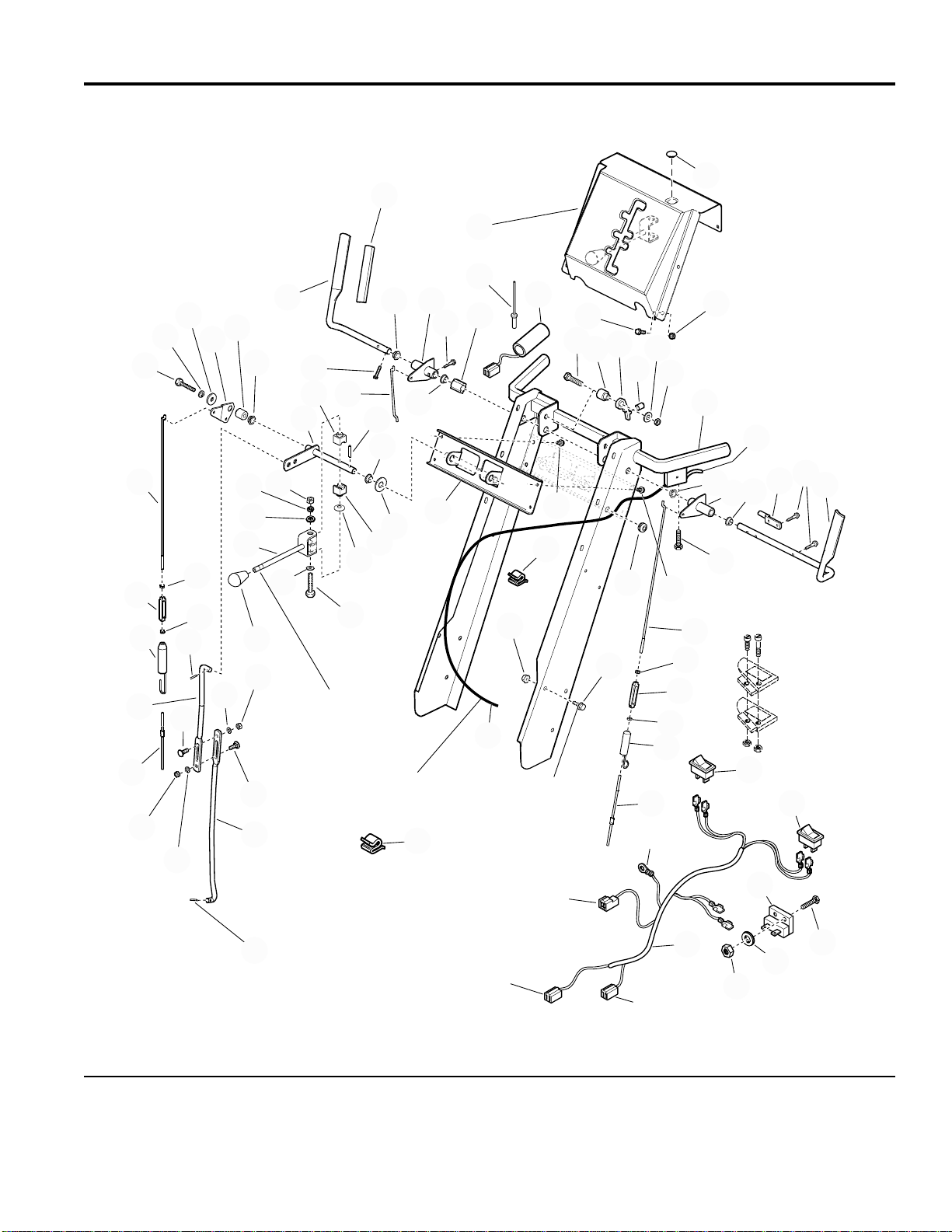
Engine and Frame Group - 13HP, Electric Start
NOTE: Unless noted otherwise,
use the standard hardware torque
specification chart.
2
Long hub of idler pulley
(Ref. 27) to be toward
idler arm (Ref. 25).
Position idler pulley (Ref. 34) at
center of slot in clutch arm (Ref. 31).
1
Use 0-2
washers
between
Ref. 58 & 31
to assure a
centered
belt and no
interference
between
pulleys Ref.
27 & 34.
58
57
57
28
32
31
29
27
30
28
25
26
23
21
Hook one end of spring (Ref. 24)
into top hole of idler arm (Ref. 25)
and other end into top hole of the
pilot arm assembly in the traction
drive group.
34
24
22
33
21
57
30
36
20
35
986155
3
59
Hook one end of spring
4
19
18
(Ref. 36) over clutch rod
5
assembly (Ref. 31)
6
between tabs and other
end into slot in frame.
7
13
14
8
9
11
10
12
15
16
17
Secure engine lead
wire for headlight to
oil filler tube.
55
Torque to
10 - 12 ft. lbs.
54
52
53
48
49
51
47
50
46
56
45
42
43
21
44
43
21
42
44
Position belt stop (Ref. 42)
1/16 to 1/8 inch from belt
when auger clutch is
engaged.
The above parts group applies to the following Mfg. Nos.:
1694237 - 1390E
1694444 - 1390E
40
41
Right rear bolt
61
60
37
38
39
© Copyright Simplicity Manufacturing, Inc. All Rights Reserved.
2003
12
TP 400-3532-01-LW-S
Page 13

Engine and Frame Group - 13HP, Electric Start
PART NO. DESCRIPTIONREF NO. QTY.
1 1672732 1 B E L T , Traction
2 1701257 1 BELT, Auger Drive
3 1725287 1 GUARD, Belt
4 1935255 2 NUT, Speed, 5/16-18
5 920426 2 LOCKWASHER, Ext. Tooth, 5/16
6 1918249 2 SCREW, Truss Head, 5/16-18 x 3/4
7 1725270 1 F R AME, Main
8 1931317 2 CARRIAGE BOLT, 1/4-20 x 3/4
9 1720404 1 SUPPORT, Clutch Cable
10 1921319 2 WASHER, 1/4
11 1916964 2 LOCKWASHER, Spring, 1/4
12 1916622 2 NUT, Hex, 1/4-20
13 1930591 2 CAPSCREW, Hex Head, Whizlock, 5/16-18 x 3/4
14 1664847 4 CAPSCREW, Hex Head, Taptite, 5/16-18 x 3/8
15 1666374 1 COVER, Bottom
16 1926018 6 NUT, Speed, 1/4-20
17 1925003 6 CAPSCREW, Hex Head, Taptite, 1/4-20 x 1/2
18 1669198 1 SUPPORT, Tie Bar
19 1930595 2 CAPSCREW, Hex Head, Whizlock, 5/16-18 x 1-1/4
20 1927557 4 NUT, Hex, Whizlock, 5/16 - 1 8
21 1919326 6 WASHER, 11/32 x 3/4
22 1702969 2 GUIDE, Belt
23 1923362 2 NUT, Hex, Centerlock, 5/16-18
24 1672735 1 SPRING, Idler
25 1703046 1 ARM, Idler, Tractio n
26 1665994 1 PIN
27 1668477 1 PULLEY, Idler
28 1928731 2 LOCKNUT, Jam, 3/8-16
29 1960647 1 CAPSCREW, Hex Head, 3/8-16 x 1-1/2
30 1918451 2 PlN,Cotter, 1/8 x 3/4
31 1612200 1 CLUTCH ROD & BRAKE ASSEMBLY
32 1669313 1 PAD, Brake
33 925160 2 RIVET, Pop
34 154534 1 PULLEY
35 1921971 1 CAPSCREW, Hex Head, 3/8-16 x 1-3/4
36 1701595 1 SPRING, Extension
37 * 1 ENGINE, Briggs & Stratton, 13 H.P. Electric Start - Engine Model # 21A414
0112E1
38 1931277 3 NUT, Hex, 5/16-18 , Black
39 1922127 3 CAPSCREW, Hex Head, 5/16-18 x 2, Black
40 1931277 1 NUT, Hex Flange, 5/16-18
Footnotes
* See your local Briggs & Stratton distributor for Parts & Service.
** Not a Servic e P ar t.
The above parts group applies to the following Mfg. Nos.:
1694237 - 1390E
1694444 - 1390E
© Copyright Simplicity Manufacturing, Inc. All Rights Reserved.
2003
13
TP 400-3532-01-LW-S
Page 14

Engine and Frame Group - 13HP, Electric Start
NOTE: Unless noted otherwise,
use the standard hardware torque
specification chart.
2
Long hub of idler pulley
(Ref. 27) to be toward
idler arm (Ref. 25).
Position idler pulley (Ref. 34) at
center of slot in clutch arm (Ref. 31).
1
Use 0-2
washers
between
Ref. 58 & 31
to assure a
centered
belt and no
interference
between
pulleys Ref.
27 & 34.
58
57
57
28
32
31
29
27
30
28
25
26
23
21
Hook one end of spring (Ref. 24)
into top hole of idler arm (Ref. 25)
and other end into top hole of the
pilot arm assembly in the traction
drive group.
34
24
22
33
21
57
30
36
20
35
986155
3
59
Hook one end of spring
4
19
18
(Ref. 36) over clutch rod
5
assembly (Ref. 31)
6
between tabs and other
end into slot in frame.
7
13
14
8
9
11
10
12
15
16
17
Secure engine lead
wire for headlight to
oil filler tube.
55
Torque to
10 - 12 ft. lbs.
54
52
53
48
49
51
47
50
46
56
45
42
43
21
44
43
21
42
44
Position belt stop (Ref. 42)
1/16 to 1/8 inch from belt
when auger clutch is
engaged.
The above parts group applies to the following Mfg. Nos.:
1694237 - 1390E
1694444 - 1390E
40
41
Right rear bolt
61
60
37
38
39
© Copyright Simplicity Manufacturing, Inc. All Rights Reserved.
2003
14
TP 400-3532-01-LW-S
Page 15

Engine and Frame Group - 13HP, Electric Start
PART NO. DESCRIPTIONREF NO. QTY.
41 1921978 1 CAPSCREW, Hex Head, 5/16-18 x 2
42 1702970 2 GUIDE, Belt
43 1917356 2 LOCKWASHER, 5/16
44 1921515 2 CAPSCREW, Hex Head, 5/16-24 x 3/4
45 1672129 1 KEY, Parallel, 3/16 x 13/16 x 7/8
46 1724454 1 PULLEY, Traction
47 1701818 1 WASHER, Thrust
48 1702425 1 SPRING, Compression
49 1701849 1 SPRING, Compression
50 ** 1 WICK, Oil (Not a Service Part)
51 1702017 1 PULLEY, Drive
52 1701776 1 PULLEY, Drive
53 1922755 1 WASHER, 13/32 x 1
54 1916965 1 LOCKWASHER, Spring, 3/8
55 1960345 1 CAPSCREW, Hex Head, 3/8-24 x 2
56 1701011 1 TIE, Self Locking
57 1924940 3 WASHER, Flat, 13/32
58 157081 1 SPACER
59 ** 1 CORD, Electric, 3 Prong (Not a Service Part)
60 1724455 1 PIPE, Oil Drain, 1/4-NPT x 11/16 Long
61 1724456 1 CAP, Hex, 1/4-NPT
Footnotes
* See your local Briggs & Stratton distributor for Parts & Service.
** Not a Servic e P ar t.
The above parts group applies to the following Mfg. Nos.:
1694237 - 1390E
1694444 - 1390E
© Copyright Simplicity Manufacturing, Inc. All Rights Reserved.
2003
15
TP 400-3532-01-LW-S
Page 16

Engine and Frame Group - 13HP, Manual Start
NOTE: Unless noted otherwise,
use the standard hardware torque
specification chart.
2
Long hub of idler pulley
(Ref. 27) to be toward
idler arm (Ref. 25).
Position idler pulley (Ref. 34) at
center of slot in clutch arm (Ref. 31).
1
Use 0-2
washers
between
Ref. 58 & 31
to assure a
centered
belt and no
interference
between
pulleys Ref.
27 & 34.
58
57
57
28
32
31
29
27
30
28
25
26
23
21
Hook one end of spring (Ref. 24)
into top hole of idler arm (Ref. 25)
and other end into top hole of the
pilot arm assembly in the traction
drive group.
34
24
22
33
21
57
30
36
20
35
986144
3
Hook one end of spring
4
19
18
(Ref. 36) over clutch rod
5
assembly (Ref. 31)
6
between tabs and other
end into slot in frame.
7
13
14
8
9
11
10
12
15
16
17
Secure engine lead
wire for headlight to
oil filler tube.
55
Torque to
10 - 12 ft. lbs.
54
52
53
48
49
51
47
50
46
56
45
42
43
21
44
43
21
42
44
Position belt stop (Ref. 42)
1/16 to 1/8 inch from belt
when auger clutch is
engaged.
The above parts group applies to the following Mfg. Nos.:
1694266 - 1390M
1694443 - 1390M
40
41
Right rear bolt
60
59
37
38
39
© Copyright Simplicity Manufacturing, Inc. All Rights Reserved.
2003
16
TP 400-3532-01-LW-S
Page 17

Engine and Frame Group - 13HP, Manual Start
PART NO. DESCRIPTIONREF NO. QTY.
1 1672732 1 B E L T , Traction
2 1701257 1 BELT, Auger Drive
3 1667516 1 GUARD, Belt
4 1935255 2 NUT, Speed, 5/16-18
5 920426 2 LOCKWASHER, Ext. Tooth, 5/16
6 1918249 2 SCREW, Truss Head, 5/16-18 x 3/4
7 1725270 1 F R AME, Main
8 1931317 2 CARRIAGE BOLT, 1/4-20 x 3/4
9 1720404 1 SUPPORT, Clutch Cable
10 1921319 2 WASHER, 1/4
11 1916964 2 LOCKWASHER, Spring, 1/4
12 1916622 2 NUT, Hex 1/4-20
13 1930591 2 CAPSCREW, Hex Head, Whizlock, 5/16-18 x 3/4
14 1664847 4 CAPSCREW, Hex Head, Taptite, 5/16-18 x 3/8
15 1666374 1 COVER, Bottom
16 1926018 6 NUT, Speed, 1/4-20
17 1925003 6 CAPSCREW, Taptite,1/4-20 x 1/2
18 1669198 1 SUPPORT, Tie Bar
19 1930595 2 CAPSCREW, Whizlock, 5/16-18 x 1-1/4
20 1927557 4 NUT, Hex, Whizlock, 5/16 - 1 8
21 1919326 6 WASHER, 11/32 x 3/4
22 1702969 2 GUIDE, Belt
23 1923362 2 NUT, Hex, Centerlock, 5/16-18
24 1672735 1 SPRING, Idler
25 1703046 1 ARM, Idler, Tractio n
26 1665994 1 PIN
27 1668477 1 PULLEY, Idler
28 1928731 2 LOCKNUT, Jam, 3/8-16
29 1960647 1 CAPSCREW, Hex Head, 3/8-16 x 1-1/2
30 1918451 2 PlN, Cotter, 1/ 8 x 3/4
31 1612200 1 CLUTCH ROD & BRAKE ASSEMBLY
32 1669313 1 PAD, Brake
33 925160 2 RIVET, Pop
34 154534 1 PULLEY
35 1921971 1 CAPSCREW, Hex Head, 3/8-16 x 1-3/4
36 1701595 1 SPRING, Extension
37 * 1 ENGINE, Briggs & Stratton, 13 H.P. Manual Start - Engine Model
#21A4160113E1
38 1931277 3 NUT, Hex, 5/16-18 , Black
39 1922127 3 CAPSCREW, Hex Head, 5/16-18 x 2, Black
40 1931277 1 NUT, Hex Flange, 5/16-18
Footnotes
* See your local Briggs & Stratton distributor for Parts & Service.
** Not a Servic e P ar t.
The above parts group applies to the following Mfg. Nos.:
1694266 - 1390M
1694443 - 1390M
© Copyright Simplicity Manufacturing, Inc. All Rights Reserved.
2003
17
TP 400-3532-01-LW-S
Page 18
Engine and Frame Group - 13HP, Manual Start
NOTE: Unless noted otherwise,
use the standard hardware torque
specification chart.
2
Long hub of idler pulley
(Ref. 27) to be toward
idler arm (Ref. 25).
Position idler pulley (Ref. 34) at
center of slot in clutch arm (Ref. 31).
1
Use 0-2
washers
between
Ref. 58 & 31
to assure a
centered
belt and no
interference
between
pulleys Ref.
27 & 34.
58
57
57
28
32
31
29
27
30
28
25
26
23
21
Hook one end of spring (Ref. 24)
into top hole of idler arm (Ref. 25)
and other end into top hole of the
pilot arm assembly in the traction
drive group.
34
24
22
33
21
57
30
36
20
35
986144
3
Hook one end of spring
4
19
18
(Ref. 36) over clutch rod
5
assembly (Ref. 31)
6
between tabs and other
end into slot in frame.
7
13
14
8
9
11
10
12
15
16
17
Secure engine lead
wire for headlight to
oil filler tube.
55
Torque to
10 - 12 ft. lbs.
54
52
53
48
49
51
47
50
46
56
45
42
43
21
44
43
21
42
44
Position belt stop (Ref. 42)
1/16 to 1/8 inch from belt
when auger clutch is
engaged.
The above parts group applies to the following Mfg. Nos.:
1694266 - 1390M
1694443 - 1390M
40
41
Right rear bolt
60
59
37
38
39
© Copyright Simplicity Manufacturing, Inc. All Rights Reserved.
2003
18
TP 400-3532-01-LW-S
Page 19

Engine and Frame Group - 13HP, Manual Start
PART NO. DESCRIPTIONREF NO. QTY.
41 1921978 1 CAPSCREW, Hex Head, 5/16-18 x 2
42 1702970 2 GUIDE, Belt
43 1917356 2 LOCKWASHER, 5/16
44 1921515 2 CAPSCREW, Hex Head, 5/16-24 x 3/4
45 1672129 1 KEY, Parallel, 3/16 x 13/16 x 7/8
46 1724454 1 PULLEY, Traction
47 1701818 1 WASHER, Thrust
48 1702425 1 SPRING, Compression
49 1701849 1 SPRING, Compression
50 ** 1 WICK, Oil (Not a Service Part)
51 1702017 1 PULLEY, Drive
52 1701776 1 PULLEY, Drive
53 1922755 1 WASHER, 13/32 x 1
54 1916965 1 LOCKWASHER, Spring, 3/8
55 1960345 1 CAPSCREW, Hex Head, 3/8-24 x 2
56 1701011 1 TIE, Self Locking
57 1924940 3 WASHER, Flat, 13/32
58 157081 1 SPACER
59 1724455 1 PIPE, Oil Drain, 1/4-NPT x 11/16 Long
60 1724456 1 CAP, Hex, 1/4-NPT
Footnotes
* See your local Briggs & Stratton distributor for Parts & Service.
** Not a Servic e P ar t.
The above parts group applies to the following Mfg. Nos.:
1694266 - 1390M
1694443 - 1390M
© Copyright Simplicity Manufacturing, Inc. All Rights Reserved.
2003
19
TP 400-3532-01-LW-S
Page 20

Auger and Impeller Group - 38"
NOTE: Unless noted otherwise,
use the standard hardware torque
specification chart.
33
16
14
15
17
18
19
986153
End of hub to be flush
with end of rolled down
4
shaft (Ref. 9).
2
Torque to 30 -34 ft-lbs.
5
7
10
10
10
11
12
13
6
32
6
8
9
31
Impeller to be posit io ned
against bearing before
tightening set screw.
1
Torque to
18-21 ft-lbs.
3
2
Marked side of worm
gear must contact against
left thrust washer to assure
proper gear mesh.
Auger assembly
stamped "R".
28
Apply grease until
it appears at ends
of auger asse mbl y
(2 places).
Auger assembly
stamped "L".
20
2929
26
21
18
25
22
15
30
15
23
Torque to 9 - 11 ft-lbs.
14
24
27
34
35
36
The above parts group applies to the following Mfg. Nos.:
1694237 - 1390E
1694266 - 1390M
1694444 - 1390E
1694443 - 1390M
© Copyright Simplicity Manufacturing, Inc. All Rights Reserved.
2003
20
TP 400-3532-01-LW-S
Page 21

Auger and Impeller Group - 38"
PART NO. DESCRIPTIONREF NO. QTY.
1 1679293 1 PULLEY, Auger Input
2 1928721 2 SETSCREW, Square Head, 5/16-18 x 1/2
3 1612187 1 IMPELLER ASSEMBLY
4 1960474 1 SETSCREW, Square Head, 3/8-16x 1/2
5 1612093 1 SEAL, Oil
6 1612149 2 BUSHING, Flange
7 1612127 1 C OLLAR, Thrust
8 936098 1 PIN, Drivelok, 3/16 x 1-1/2
9 1612129 1 SHAFT, Worm
10 918312 3 KEY, Woodruff, 3/16 x 5/8
11 1612111 1 TUBE
12 1612142 1 GEAR, Rolled Worm
13 168111 1 WASHER, Thrust
14 118118 2 SEAL
15 1923358 8 LOCKNUT, Hex, 1/4-20
16 1612137 1 CASE, Gear, RH
17 1612124 1 GASKET
18 118315 2 WASHER, Thrust
19 1612117 1 SHAFT, Auger
20 930246 1 KEY, Woodruff, 1/4 x 3/4
21 1612141 1 GEAR, Worm
22 1612136 1 CASE, Gear, LH
23 1668971 1 PLUG, Pipe, Tapered, 1/8
24 1960346 6 CAPSCREW, Hex Head, 1/4-20 x 7/8
25 1668344 2 PIN, Shear
26 1918447 2 PIN, Cotter, 3/32 x 3/4
27 1723945 1 AUGER ASSEMBLY, LH, 38"
28 1723944 1 AUGER ASSEMBLY, RH, 38"
29 921133 2 FITTING, Lube, 1/4
30 1931277 2 NUT, Hex Flange Whiz Lock, 5/16-18
31 1931333 2 CARRIAGE BOLT, 5/16-18 x 3/4
32 1723922 1 SUPPORT, Gear Box
33 1923282 2 CAPSCREW, Hex Head, 1/4-20 x 2-1/2
34 1921962 2 CAPSCREW, Hex Head, 1/4-20 x 1-3/4
35 1723931 2 SHAFT
36 1921962 2 NUT, 1/4-20
Footnotes
The above parts group applies to the following Mfg. Nos.:
1694237 - 1390E
1694266 - 1390M
1694444 - 1390E
1694443 - 1390M
© Copyright Simplicity Manufacturing, Inc. All Rights Reserved.
2003
21
TP 400-3532-01-LW-S
Page 22

Auger Housing and Chute Group - 38"
NOTE: Unless noted otherwise,
use the standard hardware torque
specification chart.
10
12
9
8
7
6
5
Plastic washer
(Ref. 3) goes
between chute
and deflector.
4
3
1
986151
13
14
15
17
18
19
18
19
16
22
17
20
23
21
2
Mount cable bracket (Ref. 20)
on right hand side of handle
using shift control bracket
hardware.
26
24
29
28
27
25
56
11
55
54
35
Scraper blade should
be on inside of housing.
57
52
19
Coat top and bottom of
chute ring with grease.
3
51
49
51
50
53
18
30
31
32
33
18
37
When installing cable,
make sure it does not
come into contact with
muffler.
34
35
36
38
39
40
7
41
42
43
44
45
The above parts group applies to the following Mfg. Nos.:
1694237 - 1390E
1694266 - 1390M
1694444 - 1390E
1694443 - 1390M
© Copyright Simplicity Manufacturing, Inc. All Rights Reserved.
2003
22
48
47
46
TP 400-3532-01-LW-S
Page 23

Auger Housing and Chute Group - 38"
PART NO. DESCRIPTIONREF NO. QTY.
1 1704446 1 GUARD & SUPPORT ASSEMBLY
2 1960001 3 CAPSCREW, Hex Washer Head, Plastite, #10-14 x 5/8
3 1931333 10 CARRIAGE BOLT, 5/16-18 x 3/4
4 960210 1 WASHER, Nylon
5 1919326 1 WASHER, 5/17, Black
6 1919438 1 NUT, Hex Lock ESNA, 5/16-18
7 1723968 1 WIRE ASSEMBLY
8 1933896 2 NUT, Hex Lock, 10-24, Black
9 1723933 1 BRACKET, Switch, Bottom
10 1723932 1 BRACKET, Switch, Top
11 1717477 1 GEAR, Chute
12 1960579 1 SCREW, Truss Head, Phillips, #10-24 x 1-5/8
13 1724205 1 SWITCH, Ch ute Rotator
14 1723967 1 SWITCH, Hand Warmer, Off, Warm, Hot
15 1724037 1 RESISTOR BLOCK
16 1723948 1 CHUTE & DEFLECTOR ASSEMBLY
17 1702219 2 SPACER
18 1921319 6 WASHER, 1/4, Black
19 1960126 4 NUT, Push, Black
20 1611945 1 ROD
21 1611939 1 SPRING, Compression
22 1700048 1 BOOT, Water
23 1720446 1 CABLE & KNOB ASSEMBLY
24 1724483 1 CABLE TIE
25 1922014 2 NUT, Hex, 5/16-1 8
26 1705920 1 BRACKET, "L"
27 1719139 1 SEAL, Rod, Chute Deflector Cable
28 1719138 1 HANDLE , Cable
29 1960600 1 SCREW, Pan Head, #8-32 x 11/16
30 1916964 3 LOCKWASHER, 1/4, Black
31 1924009 3 CAPSCREW, Hex Head, 1/4-20 x 7/8, Black
32 1923358 1 NUT, Hex Center Lock, 1/4-20, Black
33 1717480 1 PINION
34 1925205 3 CAPSCREW, Hex Head, 5/16-18 x 5/8, Black
35 1917356 7 LOCKWASHER, 5/16, Black
36 1665982 1 RETAINER, Bearing
37 108202 1 BEARING, Ball
38 1723930 1 COVER, Pinio n
39 1925003 2 CAPSCREW, Hex Washer Head, 1/4-20 x 1/2, Black
40 1715885 1 MOTOR, Electric
Footnotes
The above parts group applies to the following Mfg. Nos.:
1694237 - 1390E
1694266 - 1390M
1694444 - 1390E
1694443 - 1390M
© Copyright Simplicity Manufacturing, Inc. All Rights Reserved.
2003
23
TP 400-3532-01-LW-S
Page 24

Auger Housing and Chute Group - 38"
NOTE: Unless noted otherwise,
use the standard hardware torque
specification chart.
10
12
9
8
7
6
5
Plastic washer
(Ref. 3) goes
between chute
and deflector.
4
3
1
986151
13
14
15
17
18
19
18
19
16
22
17
20
23
21
2
Mount cable bracket (Ref. 20)
on right hand side of handle
using shift control bracket
hardware.
26
24
29
28
27
25
56
11
55
54
35
Scraper blade should
be on inside of housing.
57
52
19
Coat top and bottom of
chute ring with grease.
3
51
49
51
50
53
18
30
31
32
33
18
37
When installing cable,
make sure it does not
come into contact with
muffler.
34
35
36
38
39
40
7
41
42
43
44
45
The above parts group applies to the following Mfg. Nos.:
1694237 - 1390E
1694266 - 1390M
1694444 - 1390E
1694443 - 1390M
© Copyright Simplicity Manufacturing, Inc. All Rights Reserved.
2003
24
48
47
46
TP 400-3532-01-LW-S
Page 25

Auger Housing and Chute Group - 38"
PART NO. DESCRIPTIONREF NO. QTY.
41 172279 2 FLANGE, Bearing
42 173934 2 BEARING, Cartridge
43 172278 2 FLANGE, Bearing
44 1923325 6 CAPSCREW, Hex Head, 5/16-18 x 7/8, Black
45 1916950 4 NUT, Hex, 3/8-16, Bla c k
46 1916965 4 LOCKWASHER, 3/8
47 1924940 4 WASHER, 3/8, Black
48 1725747 2 SKID & SUPPORTS ASSEMBLY
49 1931350 4 CARRIAGE BOLT, 3/8-16 x 1, Black
50 1723921 1 BLADE, Scraper
51 1935048 15 NUT, Hex Flange Lock, 5/16, Black
52 1917372 4 NUT, Hex, 5/16-18, BlackHEX .312-18 NC-2B BLK
53 1930659 3 NUT, Retainer Speed, 5/16-18
54 1723902 1 HOUSING & IMPELLER ASSEMBLY, 38"
55 1921332 4 CAPSCREW, Hex Head, 5/16-18 x 3/4, Black
56 1715787 2 CUTTER, Drift
57 1666613 3 CHUTE RETAINERS
Footnotes
The above parts group applies to the following Mfg. Nos.:
1694237 - 1390E
1694266 - 1390M
1694444 - 1390E
1694443 - 1390M
© Copyright Simplicity Manufacturing, Inc. All Rights Reserved.
2003
25
TP 400-3532-01-LW-S
Page 26

Traction Drive Group
NOTE: Unless noted otherwise,
use the standard hardware torque
specification chart.
4
1
2
3
4
5
26
Mounted outside
of frame.
Be sure tie bar support is in place. Move axle to
left (as viewed from back) to take up end play.
Move set collar (Ref. 51) to right to remove end
play in pivot arm (Ref. 42). Torque set screw
(Ref. 45) to 10 - 14 ft-lbs.
39
40
Apply grease to
bearing areas.
45
Torque to•
18 - 21 ft-lbs.
Assemble Ref. 42, 44 & 49
with no end play. Parts
must rotate freely.
29
Mounted inside of frame.
5
6
27
28
Grease I.D. teeth•
and flange.
41
43
Torque to
10 - 14 ft-lbs.
44
Lubricate with
5W 50 Synthetic oil.
7
30
31
42
46
50
45
51
55
41
33
Mount to bracket in
8
frame weldment.
9
17
32
48
47
60
18
35
34
33
2
36
49
17
Pack groove
with grease.
3
19
3
2
52
53
62
12
11
10
20
21
56
53
61
Grease bearing
area of Ref. 62.
15
14
13
16
Apply Loctite and•
Torque to 55 - 60
in-lbs. when all parts
are against hub.
3
22
66
37
2
4
38
5
27
4
Mounted
outside of
frame.
55
Must pivot
freely.
63
Apply anti-seize
compound to wheel hub
area of Ref. 40 & 62.
64
Hook end to
top left corner
slot of frame.
Mounted
outside of
frame.
23
24
26
Mount in
hole at
upper rear
corner of
frame.
57
54
59
65
1
5
25
58
985638
Apply locktite,
torque to
8 - 10 ft-lbs.
The above parts group applies to the following Mfg. Nos.:
1694237 - 1390E
1694266 - 1390M
© Copyright Simplicity Manufacturing, Inc. All Rights Reserved.
2003
26
TP 400-3532-01-LW-S
Page 27

Traction Drive Group
PART NO. DESCRIPTIONREF NO. QTY.
1 1925205 4 CAPSCREW, Hex Head, 5/16-18 x 5/8
2 1917356 10 LOCKWASHER, 5/16
3 1917372 10 NUT, Hex, 5/16-18
4 1667341 4 RETAINER, Bearing
5 1705897 4 BEARING
6 1667340 1 SHAFT, Hex
7 1921332 3 CAPSCREW, Hex Head, 5/16-18 x 3/4
8 1725428 1 DISC, Friction
9 1665995 1 HUB, Friction Disc
10 1916950 1 NUT, Hex, 3/8-16
11 1916965 1 LOCKWASHER, 3/8
12 1669256 1 ARM ASSEMBLY, Shift w/Bushings
13 1666114 1 BUSHING, Spac e r
14 1924940 1 WASHER, Flat, 13/32
15 1923701 1 CAPSCREW, Hex Head, 3/8-16 x 2
16 1668255 1 SPRING
17 1678956 2 COLLAR, Thrust
18 1666207 1 PIN, Slide
19 1667335 1 SET COLLAR
20 1724333 2 SETSCREW, Square Head, 1/4-20 x 1/2
21 1720409 1 SPACER
22 1667331 1 SPROCKET, 10 Tooth
23 1960353 1 WASHER, Flat, 1/4
24 1916964 1 LOCKWASHER, 1/4
25 1921959 1 CAPSCREW, Hex Head, 1 /4-20 x 5/8
26 1924856 4 CAPSCREW, Hex Head Taptite, 5/16-18 x 1/2
27 960164 4 WASHER
28 1718752 1 JACKSHAFT
29 1720298 1 SPRING, Compression
30 1718689 1 CLUTCH, Sliding
31 1720078 1 ARM, Clutch
32 927732 1 RING, Retaining
33 1960114 2 WASHER, 3/4
34 1718688 1 GEAR, 10 Tooth, Stationary, Clutch
35 1679556 1 SPACER
36 1667330 1 SPROCKET, 36 Tooth
37 1718687 1 GEAR, 10 Tooth, Double D
38 1921333 3 CAPSCREW, Hex Head, 5/16-18 x 1
39 1666001 1 BUSHING
40 1720299 1 AXLE
Footnotes
The above parts group applies to the following Mfg. Nos.:
1694237 - 1390E
1694266 - 1390M
© Copyright Simplicity Manufacturing, Inc. All Rights Reserved.
2003
27
TP 400-3532-01-LW-S
Page 28

Traction Drive Group
NOTE: Unless noted otherwise,
use the standard hardware torque
specification chart.
4
1
2
3
4
5
26
Mounted outside
of frame.
Be sure tie bar support is in place. Move axle to
left (as viewed from back) to take up end play.
Move set collar (Ref. 51) to right to remove end
play in pivot arm (Ref. 42). Torque set screw
(Ref. 45) to 10 - 14 ft-lbs.
39
40
Apply grease to
bearing areas.
45
Torque to•
18 - 21 ft-lbs.
Assemble Ref. 42, 44 & 49
with no end play. Parts
must rotate freely.
29
Mounted inside of frame.
5
6
27
28
Grease I.D. teeth•
and flange.
41
43
Torque to
10 - 14 ft-lbs.
44
Lubricate with
5W 50 Synthetic oil.
7
30
31
42
46
50
45
51
55
41
33
Mount to bracket in
8
frame weldment.
9
17
32
48
47
60
18
35
34
33
2
36
49
17
Pack groove
with grease.
3
19
3
2
52
53
62
12
11
10
20
21
56
53
61
Grease bearing
area of Ref. 62.
15
14
13
16
Apply Loctite and•
Torque to 55 - 60
in-lbs. when all parts
are against hub.
3
22
66
37
2
4
38
5
27
4
Mounted
outside of
frame.
55
Must pivot
freely.
63
Apply anti-seize
compound to wheel hub
area of Ref. 40 & 62.
64
Hook end to
top left corner
slot of frame.
Mounted
outside of
frame.
23
24
26
Mount in
hole at
upper rear
corner of
frame.
57
54
59
65
1
5
25
58
985638
Apply locktite,
torque to
8 - 10 ft-lbs.
The above parts group applies to the following Mfg. Nos.:
1694237 - 1390E
1694266 - 1390M
© Copyright Simplicity Manufacturing, Inc. All Rights Reserved.
2003
28
TP 400-3532-01-LW-S
Page 29

Traction Drive Group
PART NO. DESCRIPTIONREF NO. QTY.
41 1666425 2 BUSHING
42 1670849 1 ARM ASSEMBLY, Pivot w/Bushings (Includes Reference Numbers 41, 43 &
46)
43 1666855 1 BUSHING
44 1672595 1 PULLEY, Traction
45 1928721 2 SETSCREW, Square Head, 5/16-18 x 1/2
46 1665521 1 BEARING
47 1666379 1 WASHER
48 918312 1 KEY, Woodruff, 3/16 x 5/8
49 1719879 1 DRIVE DISC W/SPINDLE
50 1919394 1 WASHER
51 8021010 1 SET COLLAR
52 1725666 1 SPRING
53 1918451 2 PIN, Cotter, 1/8 x 3/4
54 1666105 1 ROD, Pivot
55 1919438 3 NUT, Hex, Lock, 5/16-1 8
56 1919326 1 WASHER, Flat, 11/32
57 1700473 1 BELLCRANK
58 1666106 1 BUSHING, Pivot
59 1922127 1 CAPSCREW, Hex Head, 5/16-18 x 1 -3/4
60 1720300 1 GEAR & HUB ASSEMBLY, 50 Tooth
61 1930570 2 CAPSCREW, Hex Head, 5/16-18 x 1-1/2
62 1720716 1 GEAR & HUB ASSEMBLY, w/Bushing, 50 Tooth
63 921133 1 FITTING, Lube
64 960169 1 WASHER
65 1720305 1 BUSHING
66 1666980 1 CHAIN, Drive, #40
Footnotes
The above parts group applies to the following Mfg. Nos.:
1694237 - 1390E
1694266 - 1390M
© Copyright Simplicity Manufacturing, Inc. All Rights Reserved.
2003
29
TP 400-3532-01-LW-S
Page 30

Traction Drive Group
NOTE: Unless noted otherwise,
use the standard hardware torque
specification chart.
4
1
2
3
Apply loctite
4
(2 places).
5
26
Mounted outside
of frame.
Be sure tie bar support is in place. Move axle to
left (as viewed from back) to take up end play.
Move set collar (Ref. 51) to right to remove end
play in pivot arm (Ref. 42). Torque set screw
(Ref. 45) to 10 - 14 ft-lbs.
39
40
Apply grease to
bearing areas.
45
Torque to•
18 - 21 ft-lbs.
Assemble Ref. 42, 44 & 49
with no end play. Parts
must rotate freely.
29
Mounted inside of frame.
5
6
27
28
Grease I.D. teeth•
and flange.
41
43
Torque to
10 - 14 ft-lbs.
44
Lubricate with
5W 50 Synthetic oil.
7
30
31
67
42
46
50
45
51
55
41
33
Mount to bracket in
8
frame weldment.
9
17
32
48
47
60
18
35
34
33
2
36
49
17
Pack groove
with grease.
3
19
3
2
52
53
62
12
11
10
20
21
56
53
61
Grease bearing
area of Ref. 62.
15
14
13
16
Apply Loctite and•
Torque to 55 - 60
in-lbs. when all parts
are against hub.
3
22
66
37
2
4
38
5
27
4
Mounted
outside of
frame.
55
Must pivot
freely.
63
Apply anti-seize
compound to wheel hub
area of Ref. 40 & 62.
64
Hook end to
top left corner
slot of frame.
Mounted
outside of
frame.
23
24
26
Mount in
hole at
upper rear
corner of
frame.
57
54
59
65
1
5
25
58
SC985638
Apply locktite,
torque to
8 - 10 ft-lbs.
The above parts group applies to the following Mfg. Nos.:
1694444 - 1390E
1694443 - 1390M
© Copyright Simplicity Manufacturing, Inc. All Rights Reserved.
2003
30
TP 400-3532-01-LW-S
Page 31

Traction Drive Group
PART NO. DESCRIPTIONREF NO. QTY.
1 1925205 4 CAPSCREW, Hex Head, 5/16-18 x 5/8
2 1917356 10 LOCKWASHER, 5/16
3 1917372 10 NUT, Hex, 5/16-18
4 1667341 4 RETAINER, Bearing
5 1705897 4 BEARING
6 1667340 1 SHAFT, Hex
7 1921332 3 CAPSCREW, Hex Head, 5/16-18 x 3/4
8 1725428 1 DISC, Friction
9 1665995 1 HUB, Friction Disc
10 1916950 1 NUT, Hex, 3/8-16
11 1916965 1 LOCKWASHER, 3/8
12 1669256 1 ARM ASSEMBLY, Shift w/Bushings
13 1666114 1 BUSHING, Spac e r
14 1924940 1 WASHER, Flat, 13/32
15 1923701 1 CAPSCREW, Hex Head, 3/8-16 x 2
16 1668255 1 SPRING
17 1678956 2 COLLAR, Thrust
18 1666207 1 PIN, Slide
19 1667335 1 SET COLLAR
20 1724333 2 SETSCREW, Square Head, 1/4-20 x 1/2
21 1720409 1 SPACER
22 1667331 1 SPROCKET, 10 Tooth
23 1960353 1 WASHER, Flat, 1/4
24 1916964 1 LOCKWASHER, 1/4
25 1921959 1 CAPSCREW, Hex Head, 1 /4-20 x 5/8
26 1924856 4 CAPSCREW, Hex Head Taptite, 5/16-18 x 1/2
27 960164 4 WASHER
28 1718752 1 JACKSHAFT
29 1720298 1 SPRING, Compression
30 1718689 1 CLUTCH, Sliding
31 1720078 1 ARM, Clutch
32 927732 1 RING, Retaining
33 1960114 2 WASHER, 3/4
34 1718688 1 GEAR, 10 Tooth, Stationary, Clutch
35 1679556 1 SPACER
36 1667330 1 SPROCKET, 36 Tooth
37 1718687 1 GEAR, 10 Tooth, Double D
38 1921333 3 CAPSCREW, Hex Head, 5/16-18 x 1
39 1666001 1 BUSHING
40 1720299 1 AXLE
Footnotes
The above parts group applies to the following Mfg. Nos.:
1694444 - 1390E
1694443 - 1390M
© Copyright Simplicity Manufacturing, Inc. All Rights Reserved.
2003
31
TP 400-3532-01-LW-S
Page 32

Traction Drive Group
NOTE: Unless noted otherwise,
use the standard hardware torque
specification chart.
4
1
2
3
Apply loctite
4
(2 places).
5
26
Mounted outside
of frame.
Be sure tie bar support is in place. Move axle to
left (as viewed from back) to take up end play.
Move set collar (Ref. 51) to right to remove end
play in pivot arm (Ref. 42). Torque set screw
(Ref. 45) to 10 - 14 ft-lbs.
39
40
Apply grease to
bearing areas.
45
Torque to•
18 - 21 ft-lbs.
Assemble Ref. 42, 44 & 49
with no end play. Parts
must rotate freely.
29
Mounted inside of frame.
5
6
27
28
Grease I.D. teeth•
and flange.
41
43
Torque to
10 - 14 ft-lbs.
44
Lubricate with
5W 50 Synthetic oil.
7
30
31
67
42
46
50
45
51
55
41
33
Mount to bracket in
8
frame weldment.
9
17
32
48
47
60
18
35
34
33
2
36
49
17
Pack groove
with grease.
3
19
3
2
52
53
62
12
11
10
20
21
56
53
61
Grease bearing
area of Ref. 62.
15
14
13
16
Apply Loctite and•
Torque to 55 - 60
in-lbs. when all parts
are against hub.
3
22
66
37
2
4
38
5
27
4
Mounted
outside of
frame.
55
Must pivot
freely.
63
Apply anti-seize
compound to wheel hub
area of Ref. 40 & 62.
64
Hook end to
top left corner
slot of frame.
Mounted
outside of
frame.
23
24
26
Mount in
hole at
upper rear
corner of
frame.
57
54
59
65
1
5
25
58
SC985638
Apply locktite,
torque to
8 - 10 ft-lbs.
The above parts group applies to the following Mfg. Nos.:
1694444 - 1390E
1694443 - 1390M
© Copyright Simplicity Manufacturing, Inc. All Rights Reserved.
2003
32
TP 400-3532-01-LW-S
Page 33

Traction Drive Group
PART NO. DESCRIPTIONREF NO. QTY.
41 1666425 2 BUSHING
42 1670849 1 ARM ASSEMBLY, Pivot w/Bushings (Includes Reference Numbers 41, 43 &
46)
43 1666855 1 BUSHING
44 1672595 1 PULLEY, Traction
45 1928721 2 SETSCREW, Square Head, 5/16-18 x 1/2
46 1665521 1 BEARING
47 1960114 1 WASHER
48 918312 1 KEY, Woodruff, 3/16 x 5/8
49 1719879 1 DRIVE DISC W/SPINDLE
50 1919394 1 WASHER
51 8021010 1 SET COLLAR
52 1725666 1 SPRING
53 1918451 2 PIN, Cotter, 1/8 x 3/4
54 1666105 1 ROD, Pivot
55 1919438 3 NUT, Hex, Lock, 5/16-1 8
56 1919326 1 WASHER, Flat, 11/32
57 1700473 1 BELLCRANK
58 1666106 1 BUSHING, Pivot
59 1922127 1 CAPSCREW, Hex Head, 5/16-18 x 1 -3/4
60 1720300 1 GEAR & HUB ASSEMBLY, 50 Tooth
61 1930570 2 CAPSCREW, Hex Head, 5/16-18 x 1-1/2
62 1720716 1 GEAR & HUB ASSEMBLY, w/Bushing, 50 Tooth
63 921133 1 FITTING, Lube
64 960169 1 WASHER
65 1720305 1 BUSHING
66 1666980 1 CHAIN, Drive, #40
67 1924366 1 WASHER
Footnotes
The above parts group applies to the following Mfg. Nos.:
1694444 - 1390E
1694443 - 1390M
© Copyright Simplicity Manufacturing, Inc. All Rights Reserved.
2003
33
TP 400-3532-01-LW-S
Page 34

Wheels & Tires Group
NOTE: Unless noted otherwise,
use the standard hardware torque
specification chart.
1
2
3
4
W985879
6
5
9
5
8
3
10
7
The above parts group applies to the following Mfg. Nos.:
1694237 - 1390E
1694266 - 1390M
1694444 - 1390E
1694443 - 1390M
© Copyright Simplicity Manufacturing, Inc. All Rights Reserved.
2003
34
TP 400-3532-01-LW-S
Page 35

Wheels & Tires Group
PART NO. DESCRIPTIONREF NO. QTY.
1 1921978 1 CAPSCREW, Hex Head, 5/16-18 x 2
2 1919438 1 NUT, Hex Lock ESNA Light, 5/16-18
3 172353 2 VALVE STEM & CAP
4 1722762 1 WHEEL, RH
5 1722597 2 TIRE, 16 x 6.50-6
6 1722599 1 WHEEL & TIRE ASSEMBLY, RH (Includes Ref. Nos. 3, 4 & 5)
7 1722761 1 HUB, Wheel, LH
8 1722598 1 WHEEL & TIRE ASSEMBLY, LH (Includes Ref. Nos. 3, 5 & 7)
9 153038 2 TUBE, Tire
10 1666969 2 KLIK-PIN
Footnotes
The above parts group applies to the following Mfg. Nos.:
1694237 - 1390E
1694266 - 1390M
1694444 - 1390E
1694443 - 1390M
© Copyright Simplicity Manufacturing, Inc. All Rights Reserved.
2003
35
TP 400-3532-01-LW-S
Page 36

Decals Group - 1390
NOTE: Unless noted otherwise,
use the standard hardware torque
specification chart.
3
D986186
2
2
2
3
1
1
5
4
6
7
10
4
171653 2
6
5
8
9
9
The above parts group applies to the following Mfg. Nos.:
1694237 - 1390E
1694266 - 1390M
1694444 - 1390E
1694443 - 1390M
© Copyright Simplicity Manufacturing, Inc. All Rights Reserved.
2003
36
TP 400-3532-01-LW-S
Page 37

Decals Group - 1390
PART NO. DESCRIPTIONREF NO. QTY.
1 1714245 1 DECAL, Shift Pattern, RH
2 1720479 1 DECAL, Dash (Export)
2 1724078 1 D E CA L , Dash
3 1714246 1 DECAL, Shift Pattern, LH
4 1724075 1 DECAL, Stripe, 1390
5 1722641 1 DECAL, Discharge Chute Danger (Export)
5 1722674 1 DECAL, Discharge Chute Warning (Export)
6 1716532 1 DECAL, Auger Danger
6 1722642 1 DECAL, Auger Danger (Export)
7 * 1 DECAL, OPEI (Not Serviced)
8 * 1 DECAL, Decibel (Export)
8 * 1 DECAL, Patent
9 1720454 1 DECAL, Touch Up Paint Deep Orange
10 * 1 I.D. Tag (Not Serviced)
Footnotes
* Not a Service Part.
The above parts group applies to the following Mfg. Nos.:
1694237 - 1390E
1694266 - 1390M
1694444 - 1390E
1694443 - 1390M
© Copyright Simplicity Manufacturing, Inc. All Rights Reserved.
2003
37
TP 400-3532-01-LW-S
Page 38

Headlight Group
NOTE: Unless noted otherwise,
use the standard hardware torque
specification chart.
Light mounting
hardware is included
with light.
See Auger and
Impeller group
986157
1
2
See Auger and
Impeller group
The above parts group applies to the following Mfg. Nos.:
1694237 - 1390E
1694266 - 1390M
© Copyright Simplicity Manufacturing, Inc. All Rights Reserved.
2003
38
TP 400-3532-01-LW-S
Page 39

Headlight Group
PART NO. DESCRIPTIONREF NO. QTY.
1 1724246 1 HEADLIGHT SUPPORT ASSEMBLY
2 1724070 1 HEADLIGHT ASSEMBLY, (Includes Mounting Hardware)
Footnotes
The above parts group applies to the following Mfg. Nos.:
1694237 - 1390E
1694266 - 1390M
© Copyright Simplicity Manufacturing, Inc. All Rights Reserved.
2003
39
TP 400-3532-01-LW-S
Page 40

Headlight Group
NOTE: Unless noted otherwise,
use the standard hardware torque
specification chart.
986371
1
7
2
4
6
Existing
Hardware
5
3
The above parts group applies to the following Mfg. Nos.:
1694444 - 1390E
1694443 - 1390M
© Copyright Simplicity Manufacturing, Inc. All Rights Reserved.
2003
40
TP 400-3532-01-LW-S
Page 41

Headlight Group
PART NO. DESCRIPTIONREF NO. QTY.
1 1725291 1 HEADLIGHT ASEMBLY
2 1701011 2 T IE, Self Locking
3 934683 1 CLIP, Wire
4 1709256 1 LOCKWSHER, 5/16
5 1917372 1 NUT, Hex, 5/16-18
6 1725292 1 BRACKET
7 1931333 1 CARRIAGE BOLT, 5/16-18 x 3/4
Footnotes
The above parts group applies to the following Mfg. Nos.:
1694444 - 1390E
1694443 - 1390M
© Copyright Simplicity Manufacturing, Inc. All Rights Reserved.
2003
41
TP 400-3532-01-LW-S
Page 42

Page 43
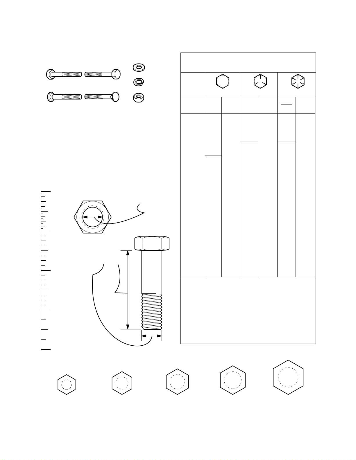
Hardware Identification & Torque Specifications
Common Hardware Types
Hex Head Capscrew
Carriage Bolt
Standard Hardware Sizing
When a washer or nut is identified as 1/2”, this is the
Nominal size
second number is present it represent the
When bolt or capscrew is identified as 1/2 - 16 x 2”, this
means the
second number represents the
example, and the final number is the
bolt or screw (in this example 2 inches long).
, meaning the
Nominal size
inside diameter
, or
body diameter
threads per inch
body length
Washer
Lockwasher
Hex Nut
is 1/2 inch; if a
threads per inch
is 1/2 inch; the
(16 in this
of the
The guides and ruler furnished below are designed to
help you select the appropriate hardware and tools.
0
1/4 3/4
1/2
Nut, 1/2”
Inside
Diameter
1
1/4 3/4
1/2
Screw, 1/2 x 2
2
1/4 3/4
1/2
3
1/4 3/4
1/2
4
Body
Diameter
Body
Length
Torque Specification Chart
FOR STANDARD MACHINE HARDWARE (Tolerance ± 20%)
Hardware
Grade
Size Of
Hardware ft/lbs Nm. ft/lbs Nm. ft/lbs Nm.
8-32
8-36
10-24
10-32
1/4-20
1/4-28
5/16-18 11 15.0 17 23.1 25 34.0
5/16-24 12 16.3 19 25.8 27 34.0
3/8-16 20 27.2 30 40.8 45 61.2
3/8-24 23 31.3 35 47.6 50 68.0
7/16-14 30 40.8 50 68.0 70 95.2
7/16-20 35 47.6 55 74.8 80 108.8
1/2-13 50 68.0 75 102.0 110 149.6
1/2-20 55 74.8 90 122.4 120 163.2
9/16-12 65 88.4 110 149.6 150 204.0
9/16-18 75 102.0 120 163.2 170 231.2
5/8-11 90 122.4 150 204.0 220 299.2
5/8-18 100 136 180 244.8 240 326.4
3/4-10 160 217.6 260 353.6 386 525.0
3/4-16 180 244.8 300 408.0 420 571.2
7/8-9 140 190.4 400 544.0 600 816.0
7/8-14 155 210.8 440 598.4 660 897.6
1-8 220 299.2 580 788.8 900 1,244.0
1-12 240 326.4 640 870.4 1,000 1,360.0
1. These torque values are to be used for all hardware
excluding: locknuts, self-tapping screws, thread forming
screws, sheet metal screws and socket head setscrews.
2. Recommended seating torque values for locknuts:
a. for prevailing torque locknuts - use 65% of grade 5
torques.
b. for flange whizlock nuts and screws - use 135% of
grade 5 torques.
3. Unless otherwise noted on assembly drawings, all torque
values must meet this specification.
No
Marks
SAE Grade 2 SAE Grade 5 SAE Grade 8
in/lbs in/lbs
19
20
27
31
66
76
2.1
2.3
3.1
3.5
7.6 8 10.9 12 16.3
8.6 10 13.6 14 19.0
30
31
43
49
NOTES
3.4
3.5
4.9
5.5
in/lbs
41
43
60
68
4.6
4.9
6.8
7.7
Wrench & Fastener Size Guide
1/4
1/4” Bolt or Nut
Wrench—7/16”
5/16
5/16” Bolt or Nut
Wrench—1/2”
3/8
3/8” Bolt or Nut
Wrench—9/16”
7/16
DIA.
7/16” Bolt or Nut
Wrench (Bolt)—5/8”
Wrench (Nut)—11/16”
1/2
DIA.
1/2” Bolt or Nut
Wrench—3/4”
Page 44

MANUFACTURING, INC.
500 N. Spring Street / PO Box 997
Port Washington, WI 53074-0997 USA
www.simplicitymfg.com
© Copyright Simplicity Manufacturing, Inc.
All Rights Reserved. Printed In USA.
2003
 Loading...