

Page 1
CP-3000 WIRELESS FIRE ALARM CONTROL
PANEL
OPERATING and INSTALLATION
INSTRUCTION MANUAL
CWSI
10798 N.W. 53 Street
Sunrise, Florida 33351
Page 2

of printing. Known corrections or omissions may be found on errata sheets included in the various
product manuals. However, Commercial Wireless Systems International
may not be held accountable for errors or omissions in this or other CWSI publications. No license is
granted by implication or otherwise under any patent rights of CWSI
a specific application. Local testing for suitability of both the proposed site and application is required.
by C
WSI or their authorized agent. The liability of CWSI for defective product is limited to the repair or
replacement of the defective product at the option of CWSI. CWSI is not liable for, nor will
reimbursement be made for the removal of, or replacement of the defective equipment or for the
inconvenience or supplemental costs which may be incurred by the installer, installing company,
dealer or end user of the equipment.
others, given verbally or in writing are valid except when signed specifically by the president of CWSI
Disclaimer
The
information contained in this document is believed to be accurate and reliable at the time
, LLC herein known as CWSI,
CWSI makes no claims as to the suitability of their products for a specific installation site or for
Unless prohibited by law, the liability of CWSI is limited to the cost of the equipment supplied
All guarantees or warranties on the products are limited to those published by CWSI and no
2
Page 3

DISCLAIMER
INTRODUCTION
SECTION 1 - DESCRIPT
1.1 Product Description and Wireless System O
1.2 Features
SECTION 2 – SPECIFIC
2.1 Specifications
2.2 Compatibility
SECTION 3 - INSTALLA
3.1 Proper Installation Order
3.2 Preparing the Installation Site
3.3 Receiving and Unpacking the Equipment
3.4 Installing the CP-3000
3.4.1 The Backup Batteries
3.
4.2 Cover Panel
3.4.3 Enrolling Devices Into the CP-3000
3.4.4 Installing the Repeaters and Initiating Devices
3.5 System Inputs and Outputs
3.5.1 Alarm A, B, C, D Contacts
3.5
.2 Trouble Contacts
3.5.3 Alarm Contacts
3.5.4 Auxiliary
3.5.5 Notification Appliance Circuits
3.5.6 Notification Appliance Compatibility
3.5.7 Ethernet
3.5.8 Telephone Line Jack
3.5.9 RS-232 DB9 Connector
....................................................................................................
...............................................................................................
ION AND FEATURES
.......................................................................................................................
ATIONS AND COMPATIBI
..............................................................................................................
...............................................................................................................
TION
.................................................................................................10
..........................................................................................................................11
.........................................................................................................................................11
..................................................................................................................16
................................................................................................................................16
...................................................................................................................................16
Output Local Energy Municipal Box Service
Connection
...........................................................................................................................20
...........................................................................................................................20
......................................................................................................................20
..........................................................................10
............................................................................................10
....................................................................................10
....................................................................................................14
...................................................................................14
........................................................................................16
............................................................................................................19
....................................................................................................19
2
5
...............................................
verview
.................................................................10
.......................................................................17
..............................................
LITY
................................
6
6
7
8
8
9
SECTION 4
4.1 User Interface
4.1.1 LCD
4.1.2 LEDS
4.1.3 Buttons
4.2 Modes of
4.2.1 Normal
4.2.2 Alarm
4.2.3 Sprinkler Supe
4.2.4 Trouble Signals
4.2.5 System Test
4.2.6 M
emory Recall
- SYSTEM O
.....................................................................................................................................................21
...................................................................................................................................................21
................................................................................................................................................21
Operation
.................................................................................................................................................23
...................................................................................................................................................23
PERATION
..............................................................................................................21
....................................................................................................23
rvisory
........................................................................................................................................25
..........................................................................................................................24
...................................................................................................................................24
....................................................................................................................................25
...............................................................21
3
Page 4

SECTION 5 - DIGITAL
SECTION 6 - SYSTEM PROGRAMMING
Appendix A - APPROVED ANTENNAS…………………………………………..28
ALARM COMMUNICATORS
........................................................25
......................................25
4
Page 5

Important: Any changes or modifications not expressly approved by the party
responsible for compliance could void the user’s authority to operate the
This device complies with part 15 of the FCC Rules. Operation is subject to the
following two conditions: (1) This device may not cause harmful interference,
and (2) this device must accept any interference received, including
of the CP-3000 RF control p
operation and should be kept for future reference. This manual consists of separate sections. Each
section contains information in a manner as to be clear as possible. It is designed to pro
information necessary to install, program and operate the equipment.
manual prior to installing or operating the equipment. It is imperative that the installer understan
requirements of the Authority Having Jurisdiction (AHJ) and be familiar with the standards set forth by
Underwriters Laboratories, NFPA
Code.
Introduction
This manual is intended for persons involved with the installation, maintenance and operation
anel. It is a comprehensive guide that provides details on product
vide all the
Read and understand this
d the
72 National Fire Alarm Code, and NFPA 70 National Electrical
The model CP-3000 is the first
manufactured by CWSI. This system was designed and tested to comply with
Alarm Code and UL
Station, Central Station and Auxiliary
FCC Warning
equip
interference that may
ment.
FCC Warning - RF Exposure
864 standard. The CP-3000 is approved for Local, Proprietary, Remote
cause undesired operation.
in a series of wireless fire annunciation and control panels
service when installed in accordance with this manual.
NFPA
72 National Fire
Important:
nearby persons has to be kept to ensure RF exposure compliance. In order to comply
with the RF exposure limits esta
between the antennas and the user should not be less than [20cm].
When using this device, a certain separation distance between antenna and
blished in the ANSI C95.1 standards, the distance
5
Page 6

Section 1 - Description and Features
1.1 Product Description and Wireless System Overview
The CWSI CP-3000 is an intelligent addressable wireless fire alarm
system provides for annunciatio
not limited to, smoke detectors, heat detectors, pull stations, water flow and sprinkler supervisory
transmitters
via radio frequency (RF). Since the communications are bi-directional the control panel can send out
control commands to perform functions including turning on or off repeater
smoke detector
failure of any one of up to 1024 initiating devices to be re
programmable making the addition of devices both easy and cost effective. Ethernet
provided for local area network
information and status to be retrieved at a remote location. An internal piezo
tones for alarm, supervisory and trouble
memory
even when all power is removed from the system. The CPou
tlined in the memory recall section of this manual. The events can later be viewed in order or
downloaded to a computer via the built in RS-232
circuit board. The on board RS-232 port can also
down loading system information.
The unit is also compatible with UL
installation solution. Th
LCD display
in alarm
control and programming
or 24 volt DC and Class A
. It has two on board tr
sounder
that will record and store events by time and date of occurrence. This memory is maintained
provides easily identifiable pinpoint information displaying the specific initiating device
, trouble
or supervisory
activation. The advanced RF protocol and speed of the CP-3000 allows a
e system is designed with monitoring and emergency personnel in mind. The
. The CP-3000 notification appliance circuits are field selectable both for 12
or B operation.
n of up to 1024 individual addressable initiating devices
ansceivers that allows all communications with devices to be done
ported within 200 seconds. It is field
connection (LAN) as well as an optional modem
signals
Listed Communicators
condition. A 21 button membrane switch panel is used for system
. The system conta
3000 is capable of storing 3000 events as
port located in the lower right side of the main
be used for site specific programming
making the CWSI CP-3000 a complete
control panel. The CP-3000
including and
NAC circuits
ins a clock
that will allow system
sounder provides distinct
and non
and tandem
connection is
-volatile
as well as
(s)
The CWSI initiating devices
directional repeaters are used to create a cellular network type signaling path to and from the CP3000 control panel. Initiating devices transmit both status and alarm information. Repeaters process
the data and retransmit the data through the repeater
control panel. All tran
conformation. The CPwhat action if any is to be taken such as displaying information
to activate Notification appliance circuits, HVAC shutdown, Elevator Recall, Tandem smoke detectors
and many other control functions.
The CP-3000 control panel has many new and enhanced features unavailable in previou
systems due to recent technological advances. These features and industry advancements are what
make CWSI the unsurpassed leader in the wireless fire alarm
smitted signals
contain microprocessor based transceivers and are battery powered. Bi
network to and from devices and the CP-3000
are verified for data integrity, signal quality and reception
3000 is responsible for reading all incoming transmission data and deciding
, sending commands back to repeaters
s wireless
industry.
6
-
Page 7

1.2 Features
1024 device
4 alarm
Bi-Directional RF communication
900 Mhz Frequency Hopping Spread Spectrum format
CRC data validation
Dual transceiver design
Tandem smoke detector
60 hour battery standby time
Field selectable NAC circuits Voltage and Class
4 N.O. programmable dry contact outputs
2 form C programmable dry cont
2 form C programmable/fixed trouble
Auxiliary
320 x 240 backlit LCD display
RS-232
Ethernet
Optional Modem for site data
Real time clock
Device enrollment
Password and key lock protected nonUser changeable password
Program
Pinpoint signal identification
History of events for
Silent or audible walk test
Printable history and maintenance log
4 site specific programmable function buttons
ca
pability
types
1 Class A
2 Class B
data port
1000 alarm
1000 supervisory
1000 annual test log signals
150 membrane switch presses
12 or 24 Volt DC @ 2 Amps
12 Volt DC @ 2 Amp each or 24 Volt DC @ 1 Amp each
municipal city box output
port
with daylight savings adjustment
mable from membrane pad or computer
feature
signals
control
/trouble
act alarm
signals
outputs
outputs
volatile memory
7
Page 8

Section 2 – Specifications and Compatibility
2.1 Specifications
Power Source
Batteries
operation.
Operating Temper
Operating Humidity
Special Application NAC Circuits: Programmable Power Limited. 1 Class “A” (Style Z) or 2 Class “B”
(Style Y) Field selectable.
Cla
Class B
Dry Contact Alarm Relays:
4 N.O. non-programmable power limited
2 Form “C” programmable power limited
Dry Contact Trouble Relays:
2 N.O. non-programmable power limited rated 28 Vdc @ 1 Amp. resistive.
2 N.C. non-programmable
: 120 VAC 60Hz 4 Amp dedicated circuit.
: Two 12Vdc 7Ah sealed lead acid batteries
ature
: 32 to 120 degrees F.
: 85% non-condensing
ss A
ratings: 12 or 24 Volts DC @ 2 Amps each
ratings: 12 Volts DC @ 2 Amps each or 24 Volts DC @ 1 Amp each
power limited
rated 28 Vdc @ 1 A
rated 28 Vdc @ 1 Amp. resistive.
rated 28 Vdc @ 1 Amp. resistive.
connected in series for up to 60 hours standby
mp. resistive.
Auxiliary
Data Port: RS-232 – 9 Pin Computer connector.
Ethernet
Telco input: RJ-11
Transceiver Operating Frequency: 900 MHz band.
Antenna
Transmission Format
Dimensions
Enclosure
Weight
output: Current 300 ma. Max coil resistance 14.6 ohms.
port connecto
Types: Yagi and Folded Dipole Omni. Max Coax length 20 ft.
: 17” high, 17” wide, 3 ¼” deep
: Powder coated 16 gauge steel
: 29 Lbs.
r: RJ-45
: Frequency Hopping – Spread Spectrum.
8
Page 9

2.2 Compatibility
The following UL Listed RF devices are compatible with the CP-3000Control Panel:
Commercial Wireless Systems International, LLC
A/C Repeater Model AR-3 – A/C powered repeater
Battery Repeater Model BR-3 – Battery powered Repeater
Smoke Detector Model 300 – Photo Electric Sm
Manual Pull Station Model 310 –
Heat Detectors models 320/321 –
Fire Transmitter Model 330 – N.O. EOL Supervised Transmitter
The following antennas
Commercial Wireless Systems International, LLC
Models:
OM-1 Omni, OM-2 Omni, YA-1 Yagi, YA
The following UL Listed Digital communicators are compatible with the CP-3000 Control
Panel:
Communicators
are to be determined. They will be activated via dry contact relay outputs
are for use with the CP-3000:
Non Coded Fire Alarm Box
Automatic Fixed and Rate of Rise Heat Detector
-2 Yagi
oke Detector with Integral Sounder
9
Page 10

Section 3 - Installation
3.1 Proper Installation Order
The following steps when performed in the li
free installation:
1. Site Signal Survey
2.
Control Panel Installation and Basic Programming
3. Device and Repeater Enrollment
4. Control Panel Site Specific Programming
5.
Repeater and Device installation and testing
sted order will result in a trouble
3.2 Preparing the Installation Site
Prior to the installation of a CP-3000 system a signal survey
trained technician or authorized dealer. The signal survey
repeaters, and initiating device
CWSI device manuals for the proper method to conduct a signal survey. The completed survey
becomes the blueprint layou
During the survey try to locate A/C repeaters and CP
uninterruptible power. All CP-3000 connections must be installed in conduit. When connecting
primary A/C power always follow
1-
National Fire and Electrical Codes (NFPA
2-
Local Electrical and Fire Code requirements
3-
Local AHJ (Authority Having Jurisdiction) requirements
WARNING: Make sure A/C supply is turned OFF prior to connecting the CP-3000
transmitters. Refer to the CWSI Signal Survey manual and individual
t for the actual installation.
-3000 control panel close to available 120 Vac
:
72 and NFPA 70)
must be been performed by a factory
determines the loc
ation of the CP-3000,
panel.
3.3 Receiving and Unpacking the Equipment
Upon receiving the equipment, the carton should be inspected for damage, which may have occurred
during shipment. Each package should be checked against the packing slip for completeness.
Differences shoul
be checked for proper operation or returned to CWSI.
d be reported to CWSI immediately. If any product is suspected of damage it should
3.4 Installing the CP-3000
WARNING: This equipment must be professionally installed by factory trained personnel. Use
of an antenna
persons, void FCC or damage the equipment.
After conducting a signal survey
should be considered and or adhered to when mounting the unit.
1 – ALL WIRING SHOUL
ELECTRICAL CODES. UN
GAUGE 7 STRAND COPPE
PREFERRED.
2 – This unit is intended to be mounted in indoor dry areas. Avoid dusty, wet and corrosive
locations.
other than listed in the compatibility section of this manual may be harmful to
the CP-
D COMPLY WITH NATIONAL AND/OR LOCAL
LESS OTHERWISE SPECI
R WITH 600 VOLT INSULATION. SHIELDED WIRE
3000 can be mounted in it’s intended loca
FIED, WIRE
10
SHOULD BE18
tion. The following
IS
Page 11

3 – Provide adequate space surrounding the unit to allow for;
a - The hinged cover to be completely opened for easy a
components and wiring.
b - The connection of conduit to the desired cabinet locations.
c – The use of the required antenna
4 – Avoid electrically noisy locat
computer rooms, telephone switching rooms, etc.
Unlock the CP
printed circuit boards are properly s
hinge pins. This will allow for easier installation. Hold the CPleveling and mark the location of the upper corner mounting keyholes
screws and anchors provided secure the screws to the wall and hang the CP-3000 control panel. If
the anchors are not the proper type for the wall, replace the anchors and screws with suitable ones.
The screws should be a #12 size minimum. Install
conduit can now be installed into the provided knockout locations required.
power limited
e
nclosure.
turned OFF prior to proceeding with A/C connection.
black transformer
Required input is 120 VAC 50-60Hz 4 Amps. Use minimum 18 AWG 600 Volt 7 strand copper wire for
A/C connections. Follow all applicable electrical codes. Attach the specified antennas to the SMA
connecto
connect any other equipment such as horns or dialers to the CP-3000 until the unit is programmed.
Do not connect the batteries
shown in figure 2 appears. If it does not, verify the following:
If all the above is correct and power up screen is still not presen
-3000 cover and open the unit. Carefully verify that the unit is not damaged and the
wiring must be in separate conduit and kept a minimum of .25” apart in the
Refer to
rs at the top of the cabinet and mount the antenna
1)
Proper input voltage is present at transformer
2) Transformer secondary connector is correctly plugged into receiver card connector
labeled J1.
3) Ribbon cable is present and plugged in between receiver
CP-3000 motherboard location J7.
figure 4
flying leads and earth gr
for suggested wire
yet. N
ions such as main electrical and transformer rooms,
ecured and connected. Remove the door by lifting it off of the
ow apply A/C power and verify the initial power up screen as
type for the installation.
screws in the two lower mounting holes. The
routing.
ound to the gray flying lead using wire nuts provided.
WARNING: Make sure A/C supply is
Connect the incoming A/C supply to the
if required. It is recommended to not
input.
ccess to internal
3000 in its intended position, verify
(Figure 3)
board location J3 and main
t, call for service.
. Using the
Power limited and non
mounting
-
3.4.1 The Backup Batteries
The cabinet houses two 12 Volt 7Amp hour batteries
hours of backup power followed by 5 minutes of alarm
manual. Once power up screen is present, install two 12 Volt 7 Amp Hour batteries and wire
shown in figure 4 using the supplied battery harness. Do not connect battery harness to the receiver
board batt
harness connector into J2 on receiver card and initial programming
detailed in the programming section of this manual. The initial programming has to be completed prior
to device
3.4.2 Cover Panel
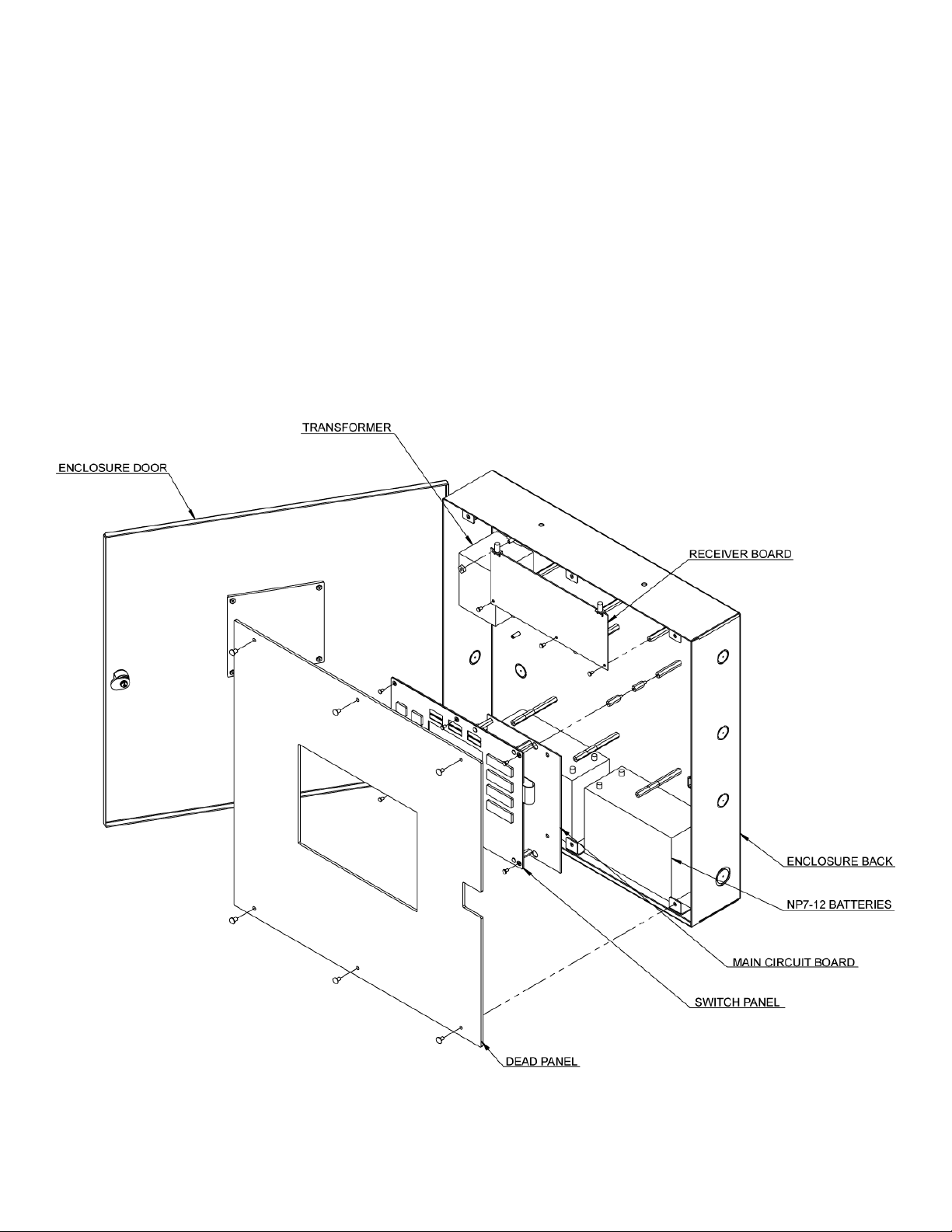
There is an optional cover panel available that attaches to the inside of the cabinet with 6 screws. It
protects the user from coming i
panel switches. Figure 5 illustrates panel location and attachment.
ery connector until A/C power has been applied to the control panel. Plug the battery
enrollment
.
wired in series. These batteries will supply 60
time at maximum alarm
of the system can begin as
n contact with the electronics but still allows full access to all control
11
load allowed in this
as
Page 12
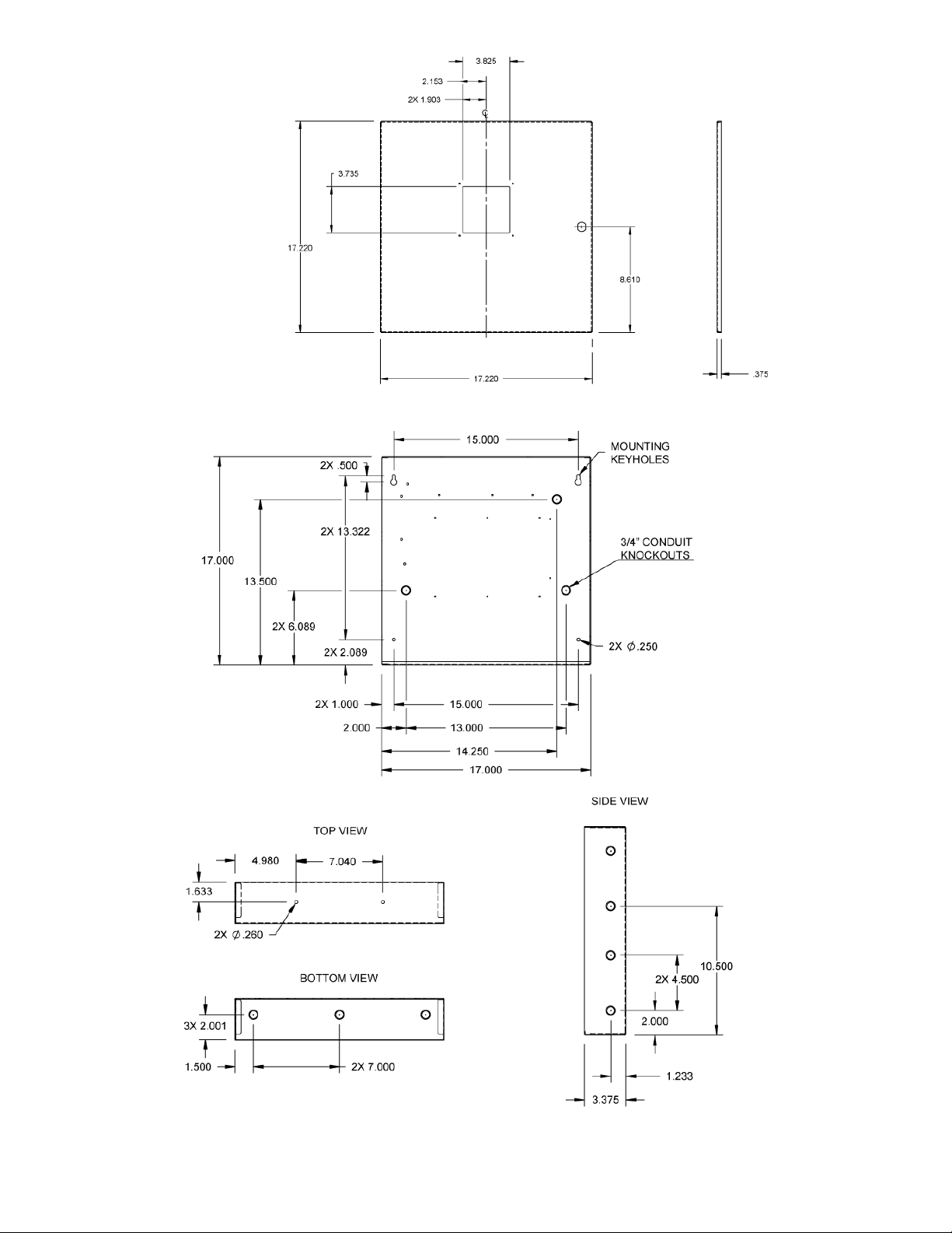
figure 3
12
Page 13
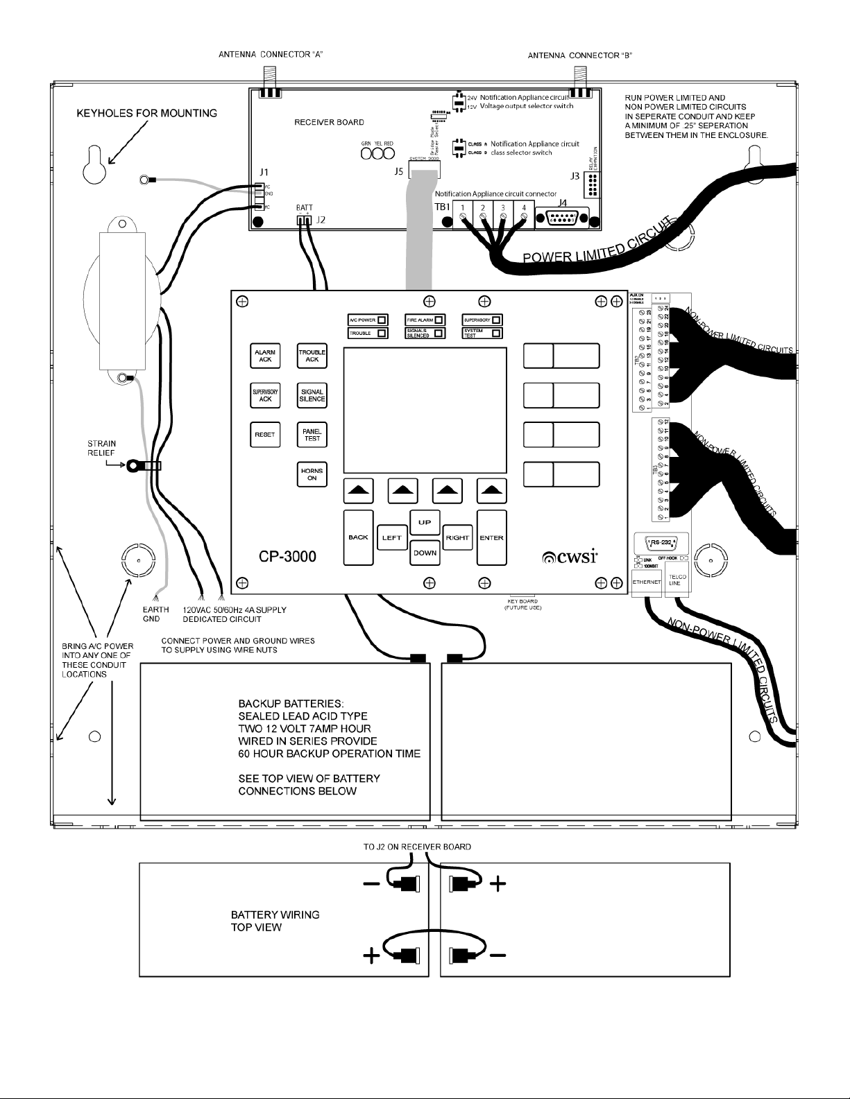
figure 4
13
Page 14

3.4.3 Enrolling Devices Into the CP-3000
Enrolling a device will both assign alarm
order to pinpoint the physical location of a device in the event an alarm or trouble
procedure can be performed only after completing the initial programming
described in the programming section of the manual. It is recommended to use a computer connected
to the RS-232
programming. The computer will allow for easier data entry especially where location designators are
being entered. Refer to the section on computer interfacing for connection instructions. Prepare a list
of device location designators prior
specific programming to be completed. To enter the enrollment mode open the cabinet to gain access
to the switch panel. Press and hold the enter button for 5 seconds. Enter your pass code th
up and down to highlight the device enrollment selection and press enter. The control panel is now in
enrollment mode and ready to accept new devices into the system. The CP-3000 has 4 alarm levels
referred to in this manual as alarms A, B, C and D. These alarm levels are prioritized with A being the
highest and D the lowest priority alarm. Each initiating device must be assigned to one of these alarm
levels. The alarm level assignment will give the device its priority in the installation. Repeate
enrolled after installing them at their mounting location and do not get assigned an alarm priority.
Install a battery into the device to be enrolled. Do not install batteries
time. When the battery i
to the device serial number. This number is also printed on a label located on the device. Use the up
down buttons to highlight the desired alarm priority for the device. Press the enter button when the
desired selection is highlighted. Alarm priority designations may now show on the LCD as
nomenclature chosen for alarms A-D during the initial programming. They will be in order of priority
from top to bottom. Upon entering the sele
successful enrollment. You will now be prompted to enter the location designator for the device. Enter
the information desired for the device. There is a maximum of XX characters. When fin
enter and the system will prompt you to end the enrollment process or go to the next device. There is
a space provided on each device label in which to write the location designation. Also a computer
print out can be generated to show the devic
This will aid in correctly installing devices in the proper locations. Proceed to enroll all devices into the
control panel as described above.
enroll a device may result in an alarm signal not being transmitted, received and processed.
port on the CP-3000 motherboard to perform enrollment
s installed the control panel LCD screen will display a number corresponding
Note: All devices must be enrolled in to the system. Fail
priority and allow specific location nomenclature entry in
to beginning enrollment. This will allow complete device and site
ction the device sounder
occurs. This
of the CP-3000 as
, data entry and
into more than one device at a
will beep twice indicating
e serial number and corresponding location designator.
site specific
en scroll
rs are
ished press
ure to
3.4.4 Installing the Repeaters and Initiating Devices
After enrolling the devices the next step is to mount the repeaters at their locations as determined by
the initial signal survey
repeater in accordance with its instruction manual again performing a signal survey prior to
permanent
procedure as described in the section above. Since there is no alarm
enrollment choice to make is the lo
installing and enrolling the balance of the repeaters. It is recommended that notification appliances
and repeaters be installed at the same time. Refer to the repeater manual for a list of notification
appliances and other equipment approved for connection to a repeater. Any equipment to be
connected to the CP-3000 such as dialers, notification appliances etc. should also be installed and
connected prior to installin
equipment. This will allow full system testing during initiating device
to visit a device location more th
then proceed with programming
Refer to the programming section of this manual for instructions and site specific programming
ly mounting the repeater. Upon applying power to the repeater perform the enrollment
. Start at the first repeater
cation designation data entry. Continue out from the panel
g initiating devices. Refer to other sections of this manual for approved
an once during the installation process. After installing the repeaters
the CP-3000 for the desired functions as needed for the installation.
location closest to the CP-3000 panel. Install the
14
priority for a repeater, the only
installation as to prevent having
Page 15
features and options. Prior to the installation and testing of the initiating devices, the control panel can
be left in normal mode for real time operation testing of the system or placed in one of the available
test modes. R
starting with the ones located closest to the control panel. Hold the first device at its desired position
and generate a signal survey transmission from it (refer to the
survey transmission). If the signal is acceptable the device may be installed at that location. Slight
transmitter location adjustments may or may not have to be made in order to obtain acceptable signal
strength result
(two beeps). Once the device is mounted confirm acceptable signal strength once more to insure
proper operation. After the device has been installed and signal verified,
alarm signal transmission and verify proper alarm reception and proper site specific programming
function operations. See the individual manuals for alarm activation methods of each device.
Continue installing the balance of the
successful one with few if any problems. After all of the equipment has been installed and powered
up be sure to place the panel in normal monitoring mode. Installation trouble
reported with in 200 seconds. Refer to the operation section of this manual for further information.
efer to system testing for these options then begin installing the initiating devices
individual device manual for signal
s. Do not mount any device unless acceptable signal strength indicating tone is heard
activate the device for an
equipment following this method and the installation will be a
with any devices will be
figure 5
15
Page 16

3.5 System Inputs and Outputs
The CP
Some are programmable and some are non programmable. Each output and function is explained
below. Refer to figures 6 and 7 for wiring diagrams of these outputs. All diagrams are shown with
system power connected and contr
3.5.1 Alarm A, B, C, D Contacts (TB2 Terminals 9-24)
These 4 normally open outputs will operate when any alarm
type is being processed. For example if alarm A has been design
smoke detector
supervisory
limited
non-power limited circuits must be separated by at least .25” within the enclosure and run in different
conduit. These outpu
have double terminals so that an end of line resistor can be connected in different terminals than
those used for wiring connections allowing connected equipment to properly monitor
Refer to the communicator section of this manual for connection of a communicator. The contacts are
rated at 28Volts D.C. 2 Amps resistive. Acceptable wire
3.5.2 Trouble Contacts (TB2 Termin
There are 2 normally open and 2 normally closed trouble
3000. They will operate during processing of any of the trouble conditions listed in the system
operati
processor failure and total power down of the control panel. The outputs can be power limited
power limited depending on
limited circuits must be separated by at least .25” within the enclosure and run in different conduit.
The normally open outputs have double terminals so that an end of line resistor can be
different terminals than those used for wiring connections allowing connected equipment to properly
monitor any wiring fault. The terminal output designations shown in figure 6 are with system power
applied in normal standby mode. One of the normally open trouble outputs is used when connecting
the control panel to a communicator. Refer to the communicator section of this manual for connection
of a communicator. When a power loss trouble occurs at the system or a repeater
trouble relays will be delayed by 60 minutes. This time is programmable and options are explained in
the programming
Acceptable wire
-3000 has 10 dry contact, 1 auxiliary
ol panel in normal mode.
and 1 class A or 2 clas
s B NAC output circuits available.
signal of the corresponding A, B, C or D
ated for smoke detectors and a
alarm is received the alarm A relay will activate. When alarm C is configured for
then the alarm C relay will serve as a supervisory output. These outputs
or non-power limited depending on the equipment they are connected to. Power limited and
ts are also used when connecting the control panel to a communicator. They
size for connection is 16-22awg.
als 1-8 N.O. and TB3 Terminals 3-6 N.C.)
dry contact outputs available on the CP
on section of this manual. These also serve as the fail safe relays
the equipment they are connected to. Power limited and non-power
section of the manual. The contacts are rated at 28Volts D.C. 2 Amps resistive.
size for connection is 16-
22awg.
that monitor for system
can be power
any wiring fault.
or non
connected in
, acti
vation of the
-
-
3.5.3 Alarm Contacts (TB3 Terminals 7-12)
These are 2 form C outputs that can be separately programmed to activate when any or all of the 4
alarm
types A, B, C or D are in process. These outputs can be p
depending on the equipment they are connected to. Power limited and non-power limited circuits
must be separated by at least .25” within the enclosure and run in different conduit. The contacts are
ra
ted at 28Volts D.C. 2 Amps resistive. Acceptable wire
C can be designated for sprinkler supervisory
program
will activate on supervisory alarm C only.
these relays
so that one of them will activate on alarms A, B and D only and the other relay
. When this programming
16
ower limited
size for connection is 16-26awg. Note: Alarm
choice is made make sure to
or non-power limited
Page 17

3.5.4 Auxiliary
This is a programmable output for connection to a city municipal box using series connection only.
Shunt connection is not supported. This output is supervised and can be programmed to activate
when any one of the 4 alarm
CP-3000 motherboard can be used to temporarily disable the auxiliary
tripping of the municipal box is not desired while performing system testing in normal mode
the jumper on pins 2+3 will disable the output. This will cause a system trouble
Removing the jumper completely or placing it on pins 1+2 will enable the output. Note: The auxiliary
output must first be programmed to activate before the auxiliary output and jumper JP1 will function.
There are also reset options available when this feature is used. Refer to the programming
further instructions. Alarm C must not be programmed to activa
designated as sprinkler supervisory
programmed to activate.
Output Ratings:
Alarm current 250ma.
Alarm voltage 3.625 Volts D.C.
Coil resistan
Max. coil resistance 14.6 ohms
Max. wire
Output Local Energy Municipal Box Service (TB3 Terminals 1+2)
types A, B, C or D ar
ce 14.5 ohms
resistance 3 ohms
. No termination resistor is needed when this output is not
e in process. A jumper labeled JP1 located on the
output. This is useful when
. Placing
to be displayed.
section for
te the auxiliary output when it is
17
Page 18
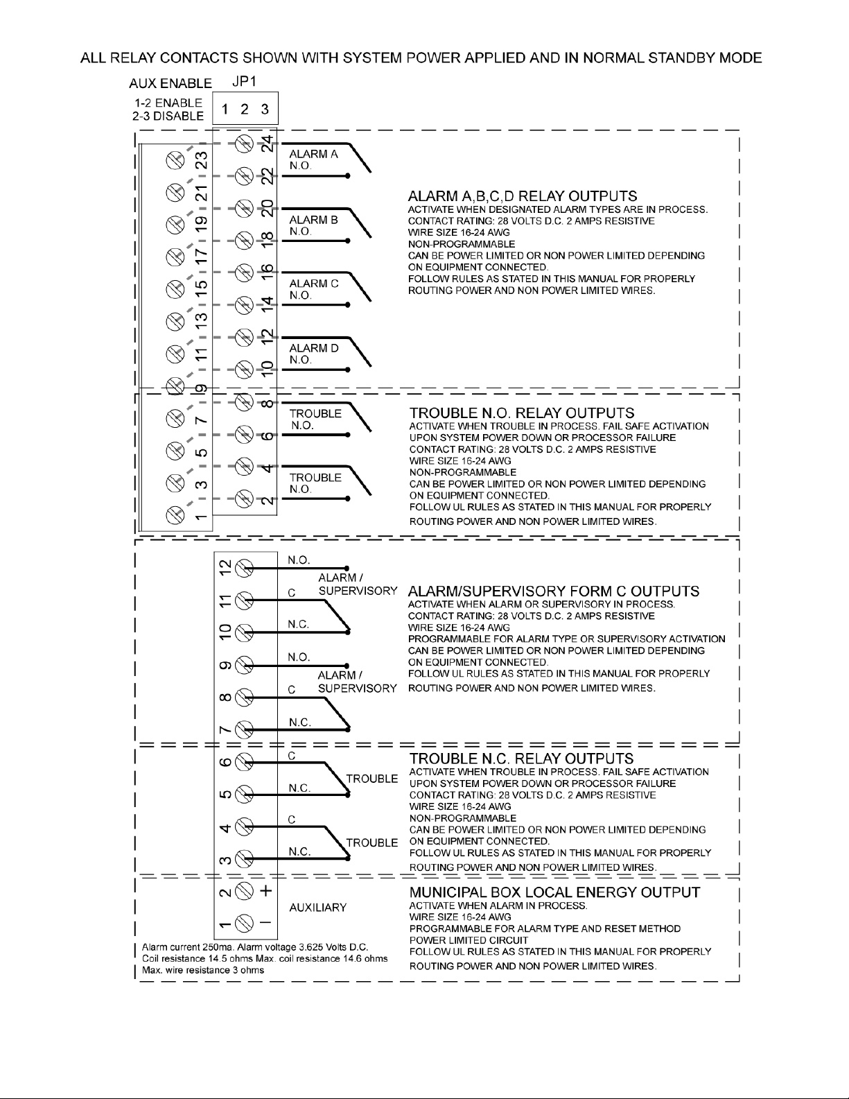
figure 6
18
Page 19

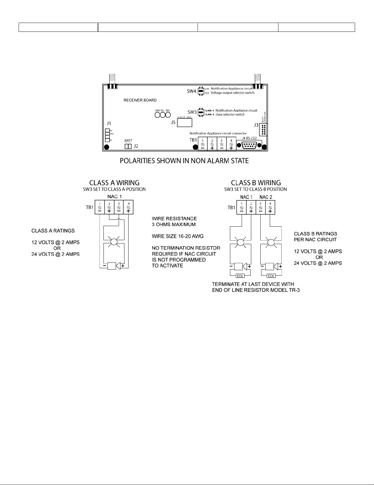
3.5.5 Notification Appliance Circuits (TB1 Terminals 1-4 on receiver
The CP-3000 control panel provides a special application notifi
selectable for either 1 Class A
voltage is also field selectable between 12 and 24 Volts D.C
by the settings of SW3 and SW4 on the receiver
located on the lower right edge of the receiver card. The CP-3000 will maintain th
voltage at either 12 or 24 volts even if the battery voltage drops below 12 or 24 volts. The NAC
circuits
programming
utilize current sensing technology and if the rated current draw is exceeded, the NAC circuit will
deactivate. It will attempt to reactivate only if another d
reset by the control panel and then reactivated by another alarm. In class B operation, an end of line
resistor P/N TR
transmitt
Figure 7 shows proper wiring of NAC circuit. Table 1 shows compatible notification appliances
Synchronization is achieved by us
Output ratings:
are also software site specific programmable for activation and deactivation. Refer to the
section for complete activation and deactivation programming options. The circuits
-3 must be placed at the last appliance connected to the circuit or a trouble will be
ed to the control panel. A trouble will also be sent if a ground fault exists on a NAC circuit.
Class B – 2 output circuits
12 Volts D.C. @ 2 Amps or 24 Volts D.C. @ 1 Amp each
Class A – 1 output circuit
12 Volts D.C. @ 2 Amps or 24 Volts D.C. @
Style Z or 2 Class B
ing one of the compatible synchronization modules.
Style Y supervised power limited
card. The NAC circuit
evice sends an alarm or the NAC circuit is
cation appliance circuit which is field
. The Class and voltage are determined
connector is labeled TB1 and
2 Amps
card)
outputs. Output
e NAC circuit output
.
3.5.6 Notification Appliance Compatibility
The following UL Listed notification appliances are compatible with the CPControl Panel
MANUFACTURER
WHEELOCK
WHEELOCK
WHEELOCK
WHEELOCK
WHEELOCK
WHEELOCK
WHEELOCK
WHEELOCK
WHEELOCK
WHEELOCK
GENTEX
GENTEX
GENTEX
GENTEX
SYSTEM SENSOR
SYSTEM SENSOR
SYSTEM SENSOR
SYSTEM SENSOR
SYSTEM SENSOR
MT4-
SM-
MODEL NUMBER
HS4-121575W-FR
MT-12/24-R OR
MT
-121575W-
AMT-12/24-R OR
RSS-121575W-FR OR
RSSP
GEH12-R OR
GES3-12 SERIES
GEC3-12 SERIES
AVSM-R OR
H12/24 SERIES
PA400 SERIES
S1224MC SERIES
P12
AS-121575W
FR OR –NW
12/24-R OR
-121575W-FR
12/24
-R
DSM-12/24
24MC SERIES
MDL
-R
H
–W
–W
–W
–FW
–W
–W
TYPE
ORN/STROBE
HORN/STROBE
HORN
HORN/STROBE
HORN
HORN
STROBE
STROBE
SYNC MODULE
SYNC MODULE
HORN
STROB
HORN/STROBE
SYNC MODULE
HORN
HORN
HORN
HORN/STROBE
SYNC MODULE
E
SW4 SETTING
12 Volts
12 Volts
12 or 24 Volts
12 Volts
12 or 24 Volts
12 or 24 V
12 Volts
12 Volts
12 or 24 Volts
12 or 24 Volts
12 Volts
12 Volts
12 Volts
12 Volts
12 or 24 Volts
12 Volts
12 or 24 Volts
12 or 24 Volts
12 or 24 Volts
3000
olts
19
Page 20
CONTACT MANUFACTURER FOR COMPLETE PART NUMBERS AND OPTIONS.
REFER TO MANUFACTURER DOCUMENTATION FOR PROPER WIRING OF SYNC MODULES
Table 1
figure 7
3.5.7
This connector can be hooked to the local area network
figure 4 for location.
3.5.8 Telephone Line Jack
This connector can be used when the option
system status information at a remote site. Uploading of site programming
through this connection. Any access through this connection will
figure 4 for location.
3.5.9 RS-232
This connector is for uploading or downloading of information such as site programming
memory
Ethernet
. Refer to figure 4 for location.
Connection
DB9 Connector
. Exact functions to be determined. Refer to
al factory installed modem
require password
20
is present. It will allow for
information is not allowed
entry. Refer to
or alarm
Page 21

Section 4 - System Operation
4.1 User Interface
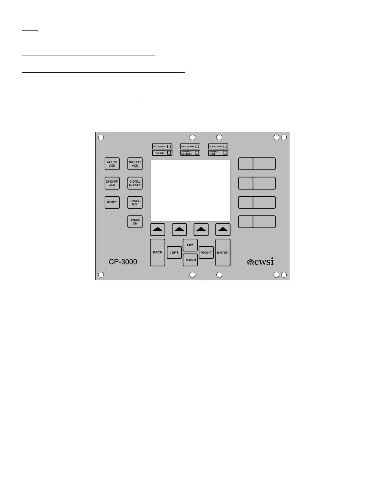
The membrane switch panel allows for means to display, control and program all aspects of the
CP-3000. Refer to figure 1.
4.1.1 LCD
The 5” diagonal 3
conditions occurring as well as programming
mentioned throughout this manual.
4.1.2 LEDS
There are 6
A/C power (green)
This LED is on when proper A/C is applied and off during brown out or total loss of A/C power.
Fire Alarm (red)
This LED flashes when at least one Alarm condition is in process. It will t
Ack or Signal Silence button is pressed. Resetting the system to normal will turn this LED off.
Supervisory (yellow)
This LED flashes when at least one Supervisory condition is in process. It will turn steady when the
Supervisor
off.
Trouble (yellow)
This LED flashes when at least one Trouble condition is in process. It will turn steady when the
Trouble Ack or Signal Silence button is pre
40 x 240 LCD backlit display allows for pinpoint status display of any abnormal
information and other useful necessary information as
led
lights for visual indication of:
urn steady when the Alarm
y Ack or Signal Silence button is pressed. Resetting the system to normal will turn this LED
ssed. Resetting the system to normal will turn this LED off.
Signals Silenced (yellow)
This LED turns on when the Signal Silence button is pressed during an Alarm condition. If NAC
circuits
System Test (green)
This LED turns on when the system is placed in test mode. Resetting the system to normal will turn
this LED off.
4.1.3 Buttons
There is a total of 21 membrane buttons, which are accessible only when the door is opened. They
provide means for total system control and programming
volatile memory.
are reactivated this led
will go
out.
. All button presses will be stored in non
21
Page 22

Buttons and functions are:
Alarm Ack
Pressing this button during an alarm
from flashing to steady. The piezo will beep once every 30 seconds until the system is reset to
normal. If a different device
simultaneous alarms will cause the screen to scroll through the displayed alarms at 5 second
intervals. Pressing the Alarm Ack button a second time will cease this rotation. The alarm display can
then be rotated using the soft key arrow
Supervisory Ack
Pressing this button during a supervisory
Supervisory LED from flashing to steady. The piezo will beep onc
to normal. If a different device
supervisory tone. More than 5 simultaneous supervisory conditions will cause the screen to scroll
through the
rotation. The display can then be rotated using the soft key arrow buttons Previous or Next.
m at 5 second intervals. Pressing the Supervisory Ack button a second time will cease this
goes into alarm, the piezo will resound an alarm. More than 5
transmits a supervisory condition, the piezo will resound the
will silence the inte
buttons Previous or Next.
will silence the internal piezo
rnal piezo
sounder
e a minute until the system is reset
and change the Fire LED
sounder
and change the
Trouble Ack
Pressing this button during a trouble
LED from flashing to steady. The piezo will beep once every 2 minutes until the system is reset to
normal. If the panel is not reset to normal within 4 hours or a diffe
condition, the piezo will resound the trouble tone. More than 5 simultaneous trouble conditions will
cause the screen to scroll through them at 5 second intervals. Pressing the Trouble Ack button a
second time
Previous or Next.
Signal Silence
This button performs the same functions as the Alarm Ack button except it will also reset any active
NAC circuits, Alarm dry contact relays
on if NAC circuits are silenced. Resetting the system to normal will turn off the Signals Silenced LED.
Reset
Pressing this butt
Auxiliary
was in test mode, it will be returned to normal standby. If any Alarm, Supervisory or Trouble that
exists after reset will cause the system to once again annunciate that condition.
Panel Test
Pressing this button will activate the Test
to choose the particular test desired. Refer to system testing for additional information. Pressing reset
will return the system to normal standby.
will cease this rotation. The display can then be rotated using the soft key arrow buttons
on will reset the system to normal. All active LED’s, NAC circuits
output, LCD display
and piezo will be restored to normal standby condi
will
silence the internal piezo
and Auxiliary
LED and display a test menu on the LCD allowing the user
output. The Signals Silenced LED will also turn
sounder
rent device
and change the Trouble
transmits a trouble
, Dry contact relays
tion. If the system
,
Horns On
This button will activate any programmed
programmed to do so. Refer to programming
alarm
if the button is p
Enter
Used for system programming
ushed when no alarm is present on the system.
. Refer to programming section.
NAC circuits
. It may also activate other relays
section for options. The piezo
22
if
will also sound for an
Page 23
Back
Used for system programming
Up, Down, Left, Right (cursor movement)
Used for system programming
4 Soft arrow keys use display for various functions
Perform functions shown on the LCD above the buttons TBD.
4 programmable site specific buttons
These buttons can be progra
elevator reset, HVAC reset etc. Custom labels can be provided. Refer to the programming
consult the factory for information.
. Refer to programming section.
. Refer to programming section.
mmed to perform various functions such as tandem
smoke reset,
section or
figure 1
4.2 Modes of Operation
4.2.1 Normal
Normal mode exists when no off normal conditions are occurring in the installation. The LCD screen
shown in figure 8 will be present during normal mode. When in normal mode the CP-3000 is
monitoring system voltages, keypad inpu
supervisory
4.2.2 Alarm
Alarms can be generated by any of the compatible initiating devices
reception of an alarm
1. Any lower priority conditions currently displayed on t
level alarm. The lower priority condition will be redisplayed when the higher one is reset.
2. The sounder
3. The Fire Alarm LED will flash once a second.
4. The correspon
or trouble
will emit a steady tone.
ts, etc. as well as monitoring for any off normal alarms,
signals
signal from an initiating device
ding alarm
. Transmitter polling signals are also logged during normal operation.
relay (1,2,3 or 4) will activate.
23
listed in this manual. Upon
the following will occur:
he LCD will be replaced by the higher
Page 24

5. The form C relays
6. The CP-3000 NAC circuit
7. Any repeater
8. The Auxiliary
9. The event is stored in the non volatile memory
The membrane buttons will function as described in
they will be displayed as each higher priority signal is reset. The LCD display
present when the system is in alarm.
4.2.3 S
Alarm C can be programmed for sprinkler supervisory
system. Upon reception of a supervisory signal the following will occur.
The membrane buttons will function as described in section 4.1.3. If lower priority signals
they will be displayed as each higher priority signal is reset. The LCD display
be present when the system is processing a supervisory
Alarm, NAC circuits
sprin
prinkler Supervisory
1. Any lower priority conditi
supervisory
2. The sounder
3.
The sprinkler Supervisory LED will flash once a second.
4. Relay 3 will activate.
5.
The event is
kler supervisory
display.
will pulse once a second.
will activate if programmed to do so.
outputs will activate if programmed to do so.
NAC ci
output will activate if programmed to do so.
rcuits
programmed to turn on will activate.
.
section 4.1.3. If lower priority signals
operation during initial programming
ons currently displayed on the LCD will be replaced by the sprinkler
stored in non volatile memory
or Auxiliary
signal.
output must not be programmed to activate upon receipt of a
.
signal.
shown in figure 9 will be
shown in figure 10 will
are present,
of the
are present,
4.2.4 Trouble Signals
A trouble
activate any NAC relays
The membrane buttons will function as described in section 4.1.3. The LCD display shown in figure
11 will be present when the system is processing a trouble
trouble signals
signal indicates a problem with a device
1. Multiple trouble
2. The sounder will pulse once every 10 seconds.
3. The trouble
4. The form C trouble
5. The event is stored in non volatile memory
1. Processor Failure – Can occur in CP-3000 panel. Ca
execute the main system program. Sounder will come on steady and trouble relay will trip.
2. Memory error – Can occur in CP-3000 control panel. Caused by CP-3000 memory
check error.
3. Tam
4. Interference – Can occur in AR-3, BR-3 repeaters or CP-3000 control panel. Caused by
5. Test Problem
6. NAC Circuit Fault – Can occur in AR-3 repeater
7. Charger Failure – Can occur in AR-3 repeater
8. Low Battery – Can occur in any CWSI battery operated or A/C powered device
per – Cased by removal of device
unrecognized signal which may interfere with transmitter reception.
seconds.
circuit, short circuit or ground fault in NAC circuit
battery charging circuit.
CP-3000 panel. Caused by battery voltage being too low.
LED will flash once a second.
in order of priority.
(s) or the control panel. Trouble signals
or alarm
signal of different types will be displayed in the order of priority.
contacts will activate.
– Caused by th
circuits. Upon reception of a trouble signal the following will occur:
.
signal. The list below shows possible
used by CP-3000 processor failing to
or exposing device battery.
e CP-3000 not receiving a device
or CP
wiring.
or CP-3000 panel. Caused by problem in
-3000 panel. Caused by an open
polling transmission within 200
do not
data
, repeater
or
24
Page 25

9. Power Loss – Can occur in AR-3 repeater
voltage present at A/C input to product. Trouble relay activation will be delayed by 90 min
10.
Maintenance Required – Can occur in model 300 smoke detector
error or hardware failure in the smoke detector head.
4.2.5 System Test
A full system test of all initiating devices
During testing the programmed NAC circuits
sent from a device
allowing for an annual testing printout to be generated by downloading the information via the RSport connected to a computer. Test log memory has a capacity of 1000 signals. The trouble
activate while the CP-3000 is in test mode. Test mode is entered by pressing the system test button
and then entering the 4 digit pass code.
4.2.6 Memory Recall
The CP-3000 has the capability of storing 1000 alarms, 1000 supervisory
keypad button presses. This information can be downloaded and printed separately or in various
groupings. These memory
. Tr
ansmitter signals
lists can also be individually cleared which requires a password.
can be performed as required by NFPA
received while in test mode are stored in a special test log
or CP-3000 control panel. Caused by low or no
utes.
. Caused by sensitivity level
or local authorities.
can be silent or activate for 5 seconds when an alarm
relay will
/trouble
1000 test and 150
is
232
Section 5 - Digital Alarm Communicators
All communicators will be connected via on board normally open dry contact outputs.
If off premise
CP
-3000 control panel. Wiring diagrams are also included to show proper connections.
This section to be completed before product is submitted. At least 2 dialers will be
s communications are required, the following DACT’S may be used for connection to the
used.
Section 6 - System Programming
This section details system programming
relay activation and deactivation (NAC circuits
submitting product. Some options will include total EVAC, EVAC by zone, relay repeater activation,
etc.
options not previously explained. This includes repeater
), delays, etc
. This section will be completed prior to
25
Page 26

A
alarm..........5, 6, 7, 12, 15, 17, 18, 22, 24, 25, 26, 27
antenna ............................................................11, 12
Antenna ...................................................................
auxiliary...........................................................17, 18
Auxiliary....................................3, 5, 7, 8, 18, 24, 26
B
batteries .......................................................8, 12, 15
Batteries...................................................................
C
Class A ......................................................6, 7, 8, 21
Class B ..........................................................7, 8, 21
clock....................................................................6, 7
Communicators.........................................3, 6, 9, 27
9
8
D
Description and Features.........................................
device ....................
devices.....................................................................
Dimensions..............................................................
Disclaimer ...............................................................
E
Enclosure................................................................
enrollment....................................................7, 12, 15
Ethernet .................................................3, 6, 7, 8, 22
F
Features...................................................................
26
6
5, 6, 7, 10, 12, 15, 24, 25, 26, 27
9
9
2
.9
7
Page 27

I
initiating devices ...................................6, 15, 25, 27
Installation.............................................................10
Order..................................................................10
Introduction.............................................................
L
LCD display ............................................6, 7, 24, 26
led..........................................................................23
loca
l area network .............................................6, 22
M
memory........................................6, 7, 22, 23, 26, 27
modem...............................................................6, 22
N
NAC circuit...............................................21, 26, 27
NAC circuits....................6, 7, 21, 23, 24, 26, 27, 28
NFPA.......................................................... 5, 11, 27
notification appliances.....................................15, 21
O
Operating Frequency...............................................
Operating Humidity.................................................
Operating Temperature ...........................................
5
8
8
8
programming 5, 6, 12, 15, 16, 18, 21, 22, 23, 24, 25,
26, 28
R
receiver............................................................12, 21
relays.........................................................18, 24, 26
repeater..................................6, 9, 15, 18, 26, 27, 28
RS
-232.......................................3, 6, 7, 8, 15, 22, 27
S
signal survey..............................................10, 11, 15
Signal Survey ........................................................10
signals................................................6, 7, 25, 26, 27
smoke detector.........................................6, 7, 17, 27
sounder..................................................6, 15, 24, 26
Specifications..........................................................
supervisory................6, 7, 17, 18, 19, 24, 25, 26, 27
T
tandem............................................................... 6, 25
transformer......................................................11, 12
Transmission Format...............................................
trouble..................6, 7, 10, 15, 16, 18, 24, 25, 26, 27
U
UL ............................................................. 5, 6, 9, 21
8
9
P
password......................................................7, 22, 27
piezo..................................................................6, 24
power limited...................................8, 11, 17, 18, 21
Power Source ..........................................................
8
W
walk test...................................................................
Weight.....................................................................
wire......................................................11, 12, 18, 19
7
9
2
Page 28

APPENDIX A
1)
2)
3)
4)
APPROVED ANTENNAS
Manufacturer - M2 Antenna Systems
Model - 914A-ISP
Isotropic gain - 14.25 dBi
Manufacturer - Antenna World
Model - COM-8804Y
Isotropic gain - 8.5 dBi
Manufacturer - Comtelco
Model - P915-SMA
Isotropic gain -
Manufacturer - Nearson
Model - S161AM-915
Isotropic gain - 2.5 dBi
-2
1 dBi
 Loading...