

Simplex TrueAlert ES 49AO-WRF-BA, TrueAlert ES 49AO-WWF, TrueAlert ES 49AO-WRS-BA, TrueAlert ES 49AO-WRF, TrueAlert ES 49AO-WWF-BA Installation Instructions Manual
...
R
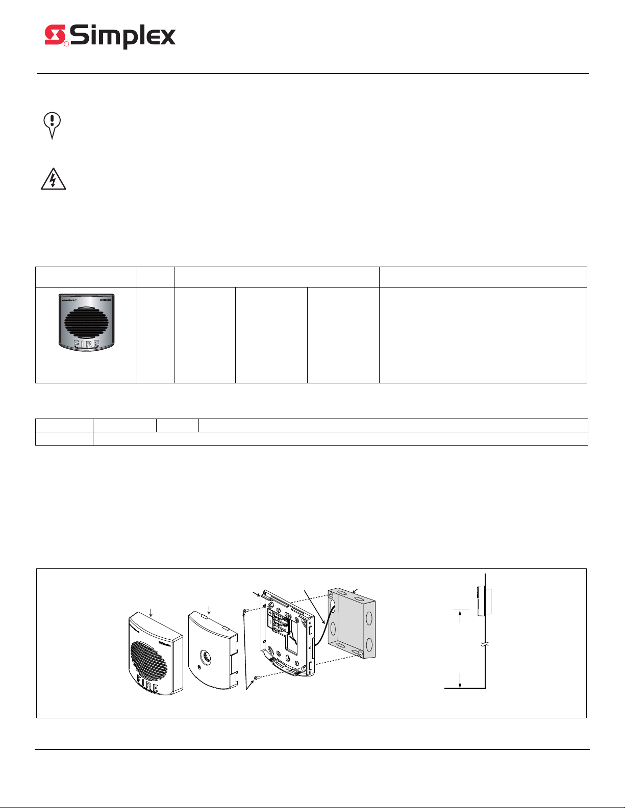
NFPA 72 requires that
the device is not
less than 80 in. (203.2 cm)
and not greater than
96 in. (243.8 cm) above
the finished floor.
Single gang, double gang, or
4 in. (101.6 mm) square electrical box
Backplate
Appliance cover
Building wire
Screws: Use 8-32 screws for a 4 in. (101.6 mm) square electrical box
Use 6-32 screws for a single or a double gang electrical box
Appliance
TrueAlert ES Addressable
Indoor A/O Notification Appliances
Installation Instructions
IMPORTANT: When the notification appliance emits light or sound, it indicates the possibility of an emergency situation that
requires the immediate attention of all occupants.
LOCATION REFERENCE: Location and quantity of appliances required must conform to the applicable local standards and
guidelines (the National Fire Alarm and Signaling Code (NFPA 72); ULC Standard CAN/ULC-S524, Installation of Fire Alarm
Systems; the appropriate model building codes, etc.) and specific requirements of the Local Authority Having Jurisdiction (AHJ).
These notification appliances are not intended for installation within hazardous locations as defined by the National Electrical
Code (NEC) or NFPA.
SAFETY: Always install, maintain, and test notification appliances within their specifications. Failure to follow all safety
precautions and instructions may result in loss of life and property due to non-functioning notification appliances. Some
notification appliances use high voltage. To avoid electrical hazards and avoid damage to appliances, make sure that the
electrical power for the notification appliance circuit is disconnected at the control panel before installing, repairing, or internally
adjusting any notification appliances. Even with electrical power removed, some notification appliances (such as visible strobes)
store a high voltage charge. The high voltage can cause injury resulting in death from electrical shock. DO NOT TOUCH
EXPOSED CIRCUITRY.
UL listed TrueAlert ES indoor product identification reference
Type Colors Models Operation
• Red
• White
Wall M oun t Ho rn
Audible Only (AO)
Note: For information about TrueAlert ES appliance testing, see TrueAlert ES Addressable Appliances testing and applications guide (579-1049).
Complete
appliances:
49AO-WRF
49AO-WRF-BA
49AO-WRS-BA
49AO-WWF
49AO-WWF-BA
49AO-WWS-BA
49AO-WRS
49AO-WRQ
Components:
49AO-APPLW
49AO-APPLW-BA
Backplate:
49MP-AVVOWR
49MP-AVVOWW
Covers:
49AOC-WRBLNG
49AOC-WRFEU
49AOC-WRFIRE
49AOC-WRS
49AOC-RBLANK
49AOC-WWBLNG
49AOC-WWFEU
49AOC-WWFIRE
49AOC-WWS
49AOC-WBLANK
These appliances provide an audible (AO) warning of an alarm
condition when activated from the control panel of a compatible
UL/ULC Listed, Simplex Fire Alarm System.
Mounting instructions
Kit contents Appliance x 1 Cover x 1 Backplate x1 with 8-32 1 inch mounting screws x 2, and 6-32 1 inch mounting screws x 2.
Not included Electrical box 1-1/2 inch (38.1 mm) minimum depth required: single gang, double gang, or 4 inch (101.6 mm) square.
1. Select the mounting location and install the electrical box using screws suitable for the mounting surface. See Figure 1 for mounting
2. Bring the building wiring through the rectangular opening in the backplate.
3. Connect the building wires to the backplate. See the wiring section on page 2.
4. Secure the backplate to the electrical box using the provided hardware. Install with the writing Install this side up at the top. Use a
5. Attach the cover to the appliance.
6. Set the appliance settings. See page 3.
7. Attach the assembled appliance onto the backplate.
and location information.
torque wrench to tighten the screws to 12-15 inch-pounds. Do not over-tighten the screws.
Figure 1. Mounting instructions
© 2014- 2017 Tyco Fire Protection Products. Specifications and other information shown were current as of publication and are subject to change without notice.
TYCO, SIMPLEX, and the product names listed in this material are marks and/or registered marks. Unauthorized use is strictly prohibited.
579-1034
Rev. F
579-1034
!
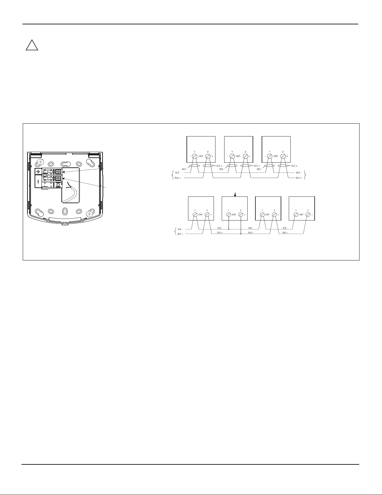
Appliance backplate
From a compatible
SLC controller,
see notes
Terminal 2
CKT+
Terminal 1
CKT-
(T-tapping example)
A/O
A/O A/O
A/O
A/O A/O
A/O
From a compatible
SLC controller,
see notes
Class A wiring, see notes
Class B wiring, see notes
To the next appliance
or compatible SLC
controller, see notes
Wiring instructions
WARNING: Make sure that all power is disconnected before starting the installation.
1. At the electrical box, connect the building wiring to the CKT + and CKT - terminals on the backplate.
2. To ensure proper continuity, use a torque wrench to tighten the terminal block screws to 12-15 inch-pounds.
3. Ensure that correct polarity is maintained for each unit.
4. Signaling Line Circuit (SLC) wiring must be twisted pair (TWP). CKT terminals accept two wires: 12-18 American Wire Gauge (AWG)
TWP .
IMPORTANT: Do not bring the conduit through the rear of the electrical box. Strip the lead insulation to 7/16 inch
maximum.
Figure 2. Wiring instructions
Wiring notes
• The maximum number of appliances on a circuit is 63. The maximum wire resistance between appliances is 26 ohms. See the field wiring diagrams
for the driving compatible fire alarm control panel for further instructions.
• Notification appliances are rated using an individual module label.
• Maintain the correct polarity on the terminal connections.
• Terminals 1 and 2 can each accommodate two wires, one wire going in and one wire going out to the next appliance.
• TrueAlert SLC wiring connections are supervised and power-limited.
• These appliances are rated to the operating voltage limits of 17-31 VDC. The appliance may fail to operate as intended, and cause permanent
damage to this equipment if it operates outside of these limits.
• Only operate the TrueAlert ES AO appliances using a compatible power supply.
• T-tapping is not permitted on Class A wiring.
2
579-1034
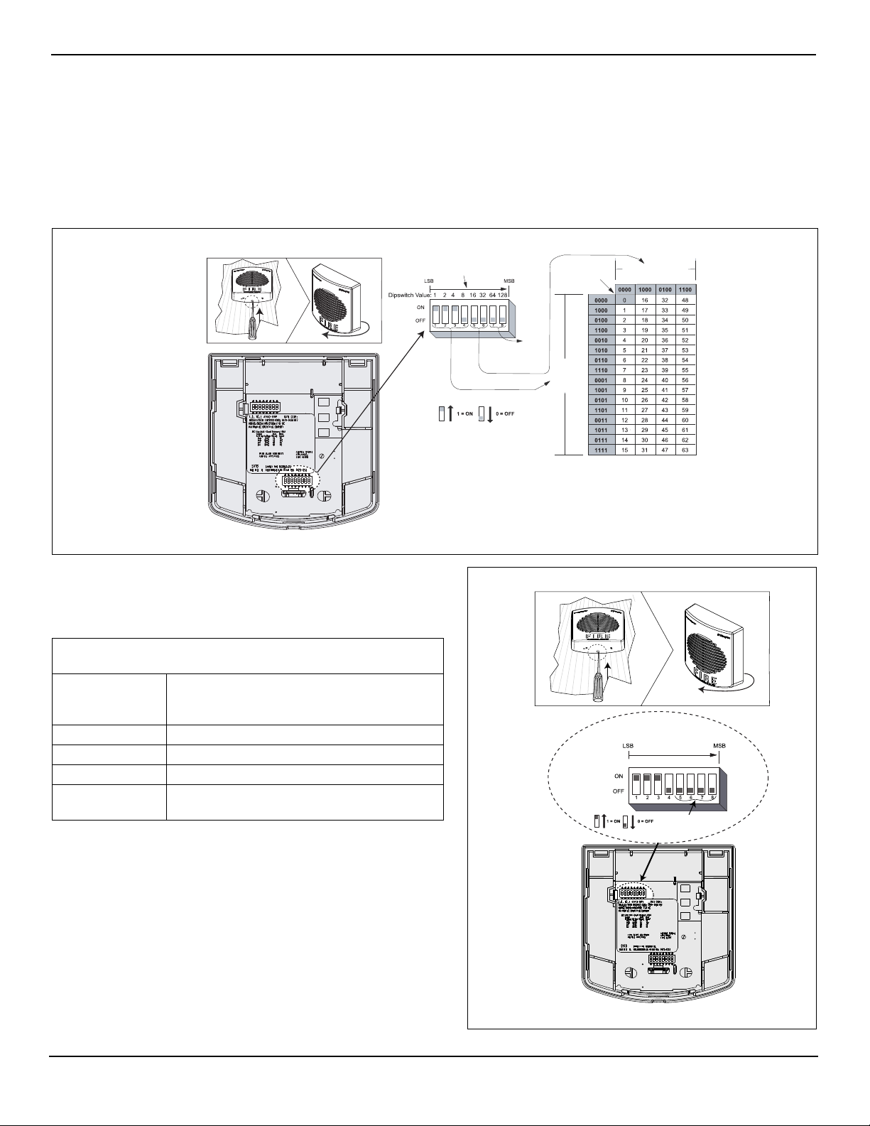
To access the switches:
ADDR1
The DIP switch shown is
set at address 7
DIP switches 5 and 6
DIP
switches
1 through 4
Not used
Reserved for
future use
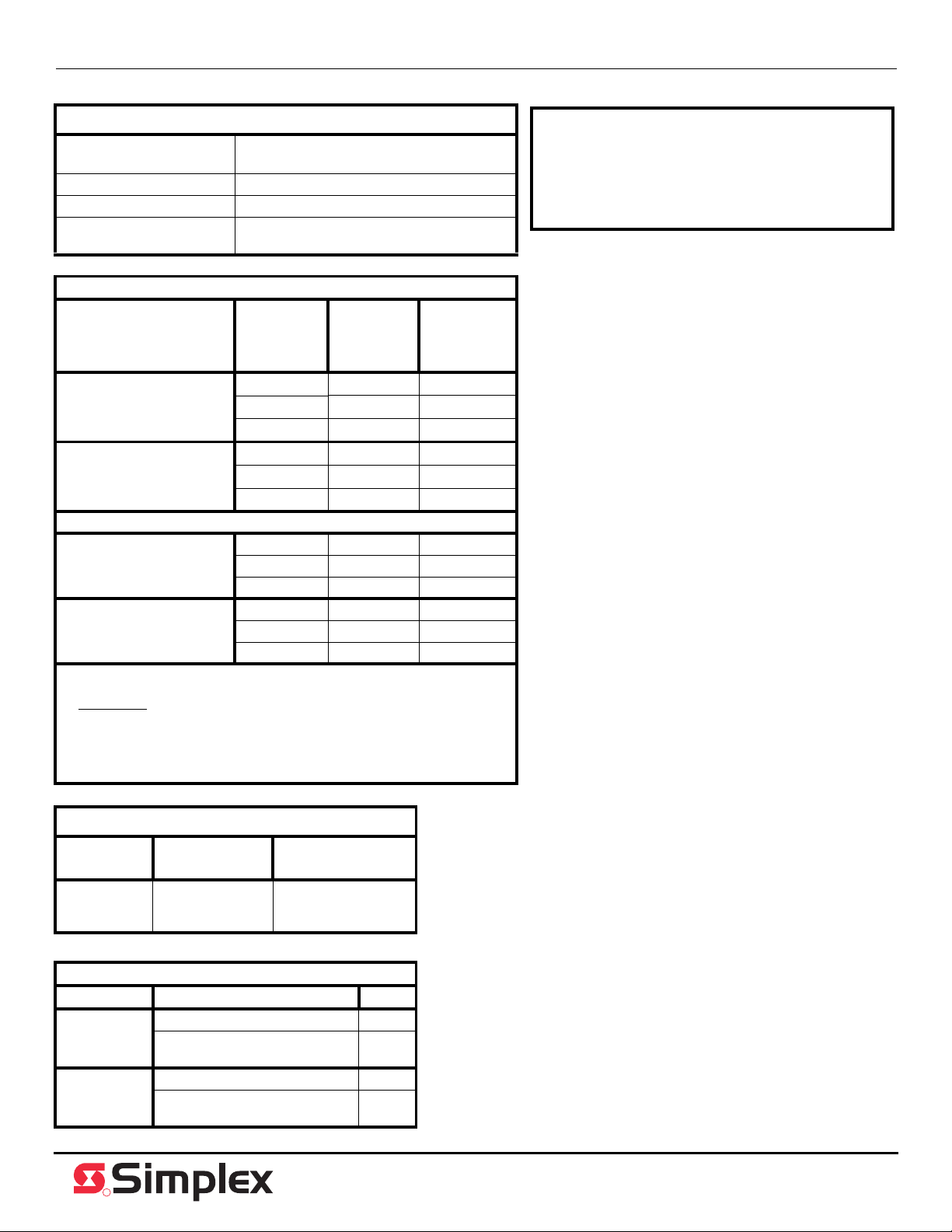
To access the switches:
Device
configuration switch
CFIG1
Not used (Leave at OFF)
Setting the address DIP switch
Each addressable TrueAlert ES notification appliance has a unique address that is set using an eight position DIP switch (ADDR1).
Assign up to 63 unique addresses to an SLC, however, the total appliance loading available may be less due to appliance current
requirements.
To set the address, complete the following steps:
1. Insert a number 1 or number 2 Phillips screwdriver, or a similar sized object, into the opening at the bottom of the appliance and
unclip the appliance from the backplate. See Figure 3.
2. Set the switches using a non-metallic stylus, or the equivalent.
3. Record the set address.
Figure 3. Setting the DIP switch address
Setting the horn configuration switch
Certain options for the horn can be configured directly on the appliance
using the Configuration switch (CFIG1) on the back of the appliance. See
Figure 4.
AO Settings
Position 1 Configuration Control: OFF to enable Local
Audible control (positions 2-7 below), ON for
Panel control.
Position 2 Audible Volume: High (OFF), Low (ON).
Position 3 CAN Horn mode: switch must be set to OFF.
Position 4 Legacy NAC mode: switch must be set to OFF.
Position 5, 6, 7,8 These switches are unused by the horn. Leave
them set to OFF.
Figure 4. Setting the appliance configuration
3
R
Appliance specifications
Environmental specifications:
Rated voltage range
Temperature range 32° F to 120° F (0° C to 49° C)
Humidity range 10% to 93%, non-condensing at 104° F (40° C)
Connections
Sound pressure level measurement (dBA)
Reverberant Room at 10
Feet in accordance with
UL464 (See Note 2)
High volume
setting using addressable
controller (See Note 3)
Low volume setting using
addressable controller
(See Note 3)
Anechoic Room at 10 feet in accordance with ULC S525, see note 4.
High volume setting 17 (Min.) 89.9 89.6
Low volume setting 17 (Min.) 84.1 83.6
Notes:
1. The coded category covers both Temporal and March time cadences.
2. Reverberant
power level measurements made in UL’s reverberant test chamber.
3. High and low volume settings are configured with DIP switch (CFIG1) on the
controller.
4. If you install the 4905-9838 Sound Damper, the anechoic measurements
decrease by approximately 9 dBA.
dBA measurements are a minimum UL rating based on sound
Special application
17 - 31 VRMS
Terminal for 18 AWG to 12 AWG
(0.82 mm
17 (Min.) 87.6 83.1
23 89.8 86
31 (Max.) 91.9 86
17 (Min.) 80.6 76.9
23 83.4 79.2
31 (Max.) 86.2 82.3
23 92.5 92.4
31 (Max.) 94.4 93.9
23 86.7 86.6
31 (Max.) 89.1 88.6
Voltage
(Vrms)
2
to 3.31 mm2)
Horn mode
steady
Horn mode
coded
(See Note 1)
CAUTION:
• The appliances are available in red and white. Do
not paint or otherwise alter the factory finishes in
any way.
• Anechoic dBA levels below 85 do not meet ULC
requirements for public notification.
Current draw
Application Appliance
type
UL464/
ULCS525
(0° C TO 50° C)
AO 23 mA
Maximum RMS
operating current
ULC directional characteristics for horn
Access
Horizontal 61.5° left and right -3 dBA
Vertical 62° up and down -3 dBA
Angle
90° left and right -4.6
90° up and down -3.8
dBA
dBA
dBA
579-1034
Rev. F
 Loading...