

Page 1

1-1
TrueAlert
™
Addre ssable Controller
Insta lla tio n Guid e
574-762
Rev. E
Page 2

1-2
Page 3

Copyright © 2005, 2007 Tyco Safety Products Westminster, Westminster, MA 01441-0001 USA.
All rights reserved.
Printed in the United States of America.
Information in this document is subject to change without notice. No part of this document may be
reproduced or transmitted in any form or by any means, electronic or mechanical, for any purpose,
without the express written consent of Tyco Safety Products.
Tyco, Simplex, the Simplex logo, IDNet and TrueAlert are trademarks of Tyco International
Services AG or its affiliates in the U.S. and/or other countries.
Copyrights and Trademarks
Page 4

Page 5

Chapter 1 Introduction to the TrueAlert Addressable Controller.... 1-1
Introduction .............................................................................................................. 1-1
In this Chapter ......................................................................................................... 1-1
Introduction to TrueAlert .............................................................................................. 1-2
Overview.................................................................................................................. 1-2
The 4009 TrueAlert Addressable Controller................................................................ 1-3
Overview.................................................................................................................. 1-3
Control Types .............................................................................................................. 1-5
Overview.................................................................................................................. 1-5
Addressable TrueAlert 4009 Control (IDNet and RUI) ........................................... 1-5
Hardwired 4009 TrueAlert Control.......................................................................... 1-5
Hardware Components................................................................................................ 1-6
Overview.................................................................................................................. 1-6
TrueAlert SLC Channels.......................................................................................... 1-6
Battery Charger ....................................................................................................... 1-6
IDNet and RUI Ports................................................................................................ 1-6
DIP Switches ........................................................................................................... 1-6
System Trouble Indicators (LEDs E-A) ................................................................... 1-8
System Trouble Messages ...................................................................................... 1-9
Isolating Earth Grounds......................................................................................... 1-10
AC Power Indicator (LED 9) .................................................................................. 1-10
Chapter 2 System Configuration and Installation.............................. 2-1
Overview.................................................................................................................. 2-1
In this Chapter ......................................................................................................... 2-1
System Overview: Applications Diagram .................................................................... 2-2
Illustration ................................................................................................................ 2-2
System Overview: Selective Signaling ........................................................................ 2-3
Illustration ................................................................................................................ 2-3
System Configuration .................................................................................................. 2-4
Overview.................................................................................................................. 2-4
SLC Appliance DIP Switches (SW1, SW2, SW3) .................................................. 2-4
Hardware Configuration DIP Switch (SW4)............................................................. 2-5
Address/Software Configuration DIP Switch (SW5)................................................ 2-8
System Installation .................................................................................................... 2-11
General Information............................................................................................... 2-11
Tools and Equipment Required............................................................................. 2-11
Required Documentation....................................................................................... 2-12
General Notes........................................................................................................ 2-12
Mounting the 4009 TrueAlert Addressable Controller ........................................... 2-13
Wiring the 4009 TrueAlert Addressable Controller................................................ 2-14
System Power Requirements ................................................................................ 2-15
Table of Contents
Page 6

Mounting and Wiring Peripheral Appliances ......................................................... 2-16
Installing Option Interfaces ........................................................................................ 2-17
Overview................................................................................................................ 2-17
Chapter 3 4010 Panel Programming ................................................... 3-1
Overview.................................................................................................................. 3-1
In this Chapter ......................................................................................................... 3-1
Overview.................................................................................................................. 3-2
Step 1: Starting the Programmer............................................................................. 3-2
Step 2: Adding an IDNet Point for the 4009 TrueAlert Addressable Controller ...... 3-3
Step 3: Configuring 4009 SLC Point Types............................................................. 3-4
Step 4: Editing Point Labels .................................................................................... 3-4
Step 5: Saving a Configuration................................................................................ 3-5
Step 6: Specifying Signal Operation........................................................................ 3-5
Deleting the 4009 TrueAlert Addressable Controller................................................... 3-6
Overview.................................................................................................................. 3-6
4010 Quick CFIG......................................................................................................... 3-7
Overview.................................................................................................................. 3-7
Quick CFIG Steps.................................................................................................... 3-7
Page 7

Figure 1-1. Simplex 4009 TrueAlert Addressable Controller .......................................... 1-3
Figure 1-2. 4009 TrueAlert Addressable Controller System Board ................................ 1-7
Figure 1-3. System Trouble Indicators ............................................................................ 1-8
Figure 2-1. 4009 TrueAlert Applications Diagram........................................................... 2-2
Figure 2-2. Selective Signaling Example ........................................................................ 2-3
Figure 2-3. SLC Appliance Settings (SW1, SW2, SW3) ................................................. 2-4
Figure 2-4. IDNet Address Settings (SW5) ..................................................................... 2-8
Figure 2-5. RUI Address Settings (SW5) ........................................................................ 2-9
Figure 2-6. Installing the 4009 Back Box ...................................................................... 2-13
Figure 2-7. 4009 TrueAlert Addressable Controller Connection Diagram .................... 2-15
List of Figures
Page 8

Page 9

1-1
The 4009-9401 TrueAlert
™
Addressable Controller is a self-contained adjunct panel for use with
TrueAlert addressable notification appliances. The base version of the Addressable Controller is a
single-board system consisting of three Signaling Line Circuit (SLC) channels, a power supply
and charger, slave interfaces for IDNet
™
and RUI protocols, and two conventional Notification
Appliance Circuit (NAC) inputs for hardwired control. Option cards are available to provide the
following additional capabilities:
• 4009-9812 Class A Adapter Option Card. Allows fault tolerance in the case of
open circuit wiring faults on the three TrueAlert SLCs.
• 4009-9809 IDNet Repeater Option Card. 4010 only. Regenerates and provides a
power and distance boost for the IDNet channel. The 4009-9809 takes the IDNet signal
from the 4009 receiver and retransmits it on its output side at host panel IDNet levels.
When the IDNet Repeater Option Card is used, the Fiber Optic Receiver Option Card is
not available for the 4009 TrueAlert Addressable Controller.
• 4009-9810 (Class B)/4009-9811 (Class A) Fiber Optic Receiver Option Card.
4010 only. Receives IDNet communication over a fiber optic link and regenerates the
IDNet signal. The Fiber Optic Receiver Option Card is used with the 4090-9105
(Class B)/4090-9107 (Class A) Fiber Optic Card to form an IDNet fiber optic link.
The table below lists the topics in this chapter.
Topic See Page
Introduction to TrueAlert 1-2
The 4009 TrueAlert Addressable Controller 1-3
Control Types 1-5
Hardware Components 1-6
Chapter 1
Introduction to the TrueAlert
Addressable Controller
Introduction
In this Chapter
Page 10

1-2
TrueAlert notification appliance operation provides power, control, and supervision of horns and
strobes over a single pair of wires. The controlling TrueAlert channel digitally communicates with
each appliance and receives a response to verify the appliance’s presence on the channel. When
required, the TrueAlert channel provides a digital command to control appliance operation.
(Typical operation would be for both horns and strobes to be initially activated upon alarm and
then, when desired, horns can be silenced while the strobes continue to flash. When the alarm
condition is over, both appliance types can be de-energized.)
Due to the supervision provided, TrueAlert notification appliances can be wired in a Class B
(Style 4) configuration without requiring traditional in/out wiring methods. Both separate branch
wiring and T-tapping are allowed in these cases. Class A (Style 6) operation does require
traditional in/out wiring methods. Up to 63 appliances can be supported on a single TrueAlert
channel.
Each TrueAlert notification appliance contains an electronic module and a selectable address
setting (in addition to its notification appliance) that allows it to occupy a unique location on the
TrueAlert channel. This on-board module also allows the TrueAlert channel to perform appliance
diagnostics that assist with installation and subsequent test operations. A visible LED at each
TrueAlert appliance can be set up to provide verification of communication, and flashes with the
appliance’s address setting when locally requested using a magnetic test tool.
Introduction to TrueAlert
Overview
Page 11

1-3
Figure 1-1 is an illustration of the TrueAlert Addressable Controller.
Figure 1-1. Simplex 4009 TrueAlert Addressable Controller
The TrueAlert Addressable Controller provides the TrueAlert channel interface between fire
alarm control panels (FACPs) that do not support TrueAlert operation, and the TrueAlert
appliances. It provides three TrueAlert channels that supply 2.5 amperes of alarm current each,
and an auxiliary 0.5-amp output. Panels that do not support TrueAlert operation cannot take
advantage of all the features of TrueAlert notification appliances, but the TrueAlert Addressable
Controller provides these panels with various capabilities that depend on the interface being used.
There are three possible interfaces to the TrueAlert Addressable Controller that the FACP can use
to control operation of the appliances.
The Simplex 4010 FACP can interface to the TrueAlert Addressable Controller via an IDNet
Interface. When using this interface, the TrueAlert Addressable Controller appears to the 4010 as
an IDNet addressable peripheral. Each of the three TrueAlert SLC channels looks to the 4010 like
a TrueAlert Non-Addressable NAC with independent control of horns and strobes. This provides
greater selective control. Diagnostic features are enabled and disabled via DIP switches in the
panel. Up to five TrueAlert Addressable Controllers can be used with a 4010 host (see Field
Wiring Diagram
842-158).
The Simplex 4100 or 4020 FACPs can interface to the TrueAlert Addressable Controller via a
Remote Unit Interface (RUI). Diagnostic features are enabled and disabled through the front panel
user interface. The quantity of TrueAlert Addressable Controllers that can be used is limited only
by the number of card addresses available (out of the total of 119).
Continued on next page
The 4009 TrueAlert Addressable Controller
Overview
Page 12

1-4
The Hardwired NAC Interface uses two conventional NACs from the host FACP. One NAC is
used to enable operation of the strobe appliances (so that they are On Until Silenced), and a
second NAC is used to enable operation of the horn appliances (so that they are On Until Reset).
All three SLC channels of the TrueAlert Addressable Controller are controlled together.
Diagnostic features are enabled and disabled via DIP switches in the panel. Up to four hardwired
TrueAlert Addressable Controllers can be used with a single host panel (see Field Wiring
Diagram 842-158).
Alternatively, the first of the two host NACs can be set up to control audible and visible output for
TrueAlert SLC Channel 1, while the second host NAC controls audible and visible output for
TrueAlert SLC Channels 2 and 3. With this type of operation, there is no individual control of
audibles and visibles.
For any of the described applications, the TrueAlert Addressable Controller can minimize
transmission line losses associated with sending large currents for notification appliances long
distances within buildings. In a fire alarm system with the TrueAlert Addressable Controller, a
power supply and batteries for notification appliances are located near the actual notification
appliances, saving system power and battery capacity while minimizing line losses.
The 4009 TrueAlert Addressable Controller, Continued
Overview, continued
Page 13

1-5
The 4009 TrueAlert Addressable Controller can be used with addressable IDNet or RUI systems.
It can also be used with hardwired FACPs. This section discusses these general uses.
The TrueAlert Addressable Controller is addressable when configured as an IDNet or RUI
peripheral. In the IDNet or RUI modes, SW5 (see Figure 1-2) sets the address of the Addressable
Controller which is controlled and configured by the 4010 FACP (for IDNet) or the 4100/4020
(for RUI). The Addressable Controller monitors each SLC. If a trouble occurs, faults (including
appliance supervision, power, battery integrity, and earth) are communicated to the host panel as
IDNet or RUI messages.
When wired to a 4100U, visual synchronization is possible. A maximum of 39 multicandela
addressable visuals may be synchronized per SLC. All SLCs are synchronized across a 4009T. All
4009Ts are synchronized across the 4100U.
There are two hardwired NAC control inputs on the Addressable Controller which can be used to
activate the appliances connected to the Addressable Controller. The hardwired NAC control
inputs provide backward compatibility with other Simplex panels. In the hardwired mode, the
configuration of the Addressable Controller is configured via two DIP switches (Hardware
Configuration Switch (SW4) and Address/Software Configuration Switch (SW5)). Each input
(called Hardwire Control Channel 1 and Channel 2, respectively, on TB7) simulates a typical
hardwired notification appliance, as seen from the host panel. The host NAC that is connected to
Channel 1 sends general trouble messages to the host panel, while the NAC connected to Channel
2 sends SLC channel-related messages to the host panel.
An End Of Line Resistor (EOLR) may be directly connected to the hardwire control Channel 1
and 2 terminals, or NAC wiring can be continued on to the next termination point for that circuit.
See Field Wiring Diagram 842-158 for details.
A maximum of four TrueAlert Addressable
Controllers can be attached to the Hardwire Control Channel 1 and Channel 2 inputs.
Control Types
Overview
Addressable
TrueAlert 4009
Control (IDNet
and RUI)
Hardwired 4009
TrueAlert Control
Page 14

1-6
This section describes the hardware on the 4009 board. Use Figure 1-2 to locate the items
described on this page.
The Addressable Controller system board provides three TrueAlert SLC channels. Channels 1
through 3 are Class B TrueAlert signaling line circuits. Field wiring terminations are provided for
12 AWG to 18 AWG wire (twisted pair wire is required). Refer to Field Wiring Diagram 842-158
for complete wiring, compatible appliances, current, and line distance information. Each channel
is capable of being independently controlled by the TrueAlert 4009, as commanded by the host
panel and Dip Switch SW5 settings.
Each signaling line circuit is monitored for short and open circuit line faults when in the standby (not
energized) condition. In the event of a short circuit, the Addressable Controller will not activate the
SLC channel while the short circuit fault is present. Short and open circuit faults are reported to the
host panel via the command channel (IDNet, RUI, or hardwired) and can be identified by a steady
trouble LED on the Addressable Controller during the supervisory state.
The channels are configurable as Class A (Style 6) circuits with the addition of the
4009-9812 Class A Adapter Option Card. The Addressable Controller monitors for insertion of the
Class A Adapter Option Card, and detects it when it is configured properly via Hardware
Configuration Switch SW4 (see Table 2-1 in Chapter 2).
On power-up, or on controller reset via DIP switch SW4 (IDNet and Hardwired only) or SW5,
each channel momentarily disconnects its supervision, allowing earth fault isolation.
The battery charger charges lead acid batteries up to 18 AH (refer to Field Wiring Diagram
842-158 for details). Low, missing, and depleted batteries are detected through supervision. The
battery charger output remains disabled until a battery is sensed. The 4009 does not support
external chargers.
The control interfaces for IDNet and RUI are TB1 and TB2. Use these ports as described in Field
Wiring Diagram 842-158.
DIP switches are used to configure the system, as described in Chapter 2.
Continued on next page
Hardware Components
Overview
TrueAlert SLC
Channels
Battery Charger
IDNet and RUI Ports
DIP Switches
Page 15

1-7
Figure 1-2. 4009 TrueAlert Addressable Controller System Board
Continued on next page
Hardware Components, Continued
TB3, TB4, TB5
TRUEALERT SLC
CHANNELS
TB2
IDNet CONTROL INTERFACE
P4
IDNet REPEATER CARD
or FIBER RECEIVER
CARD
H1 (RED WIRE), H2 (BLACK W IRE)
MAIN POWER INPUTS FROM BRIDGE
RECTIFIER
TB8
BATTERY TERMINAL
P5 (ORANGE WIRE)
P6 (YELLOW WIRE)
CHARGER INPUTS
FROM TRANSF0RMER
TB7
NAC CONTROL
INTERFACE
(HOST NAC IN)
TB6
AUXILARY POWER
OUTPUT
(0.5 AMP AVAILABLE)
P2 AND P3
FOR CLASS A
ADAPTER CARD
LED 9
AC POWER
INDICATOR
LED(s) E-A
TROUBLE INDICATORS
SW4
HARDWARE
CONFIGURATION
DIP SWITCH
TB1
RUI CONTROL
INTERFACE
SW5
ADDRESS/SOFTWARE
CONFIGURATION
DIP SWITCH
SW1, SW2,
SW3
SLC DEVICE
SWITCHES
PB-SW6
TROUBLE SCROLL
PUSHBUTTON
SLC LEDs
(CH1-CH3)
Page 16
1-8
The system trouble indicators consist of a bank of five yellow LEDs (see Figure 1-2 for location
of LEDs) that are used to signify various trouble conditions within the Addressable Controller
system. Only one trouble at a time is indicated, with the highest trouble state indicated first. When
that trouble clears, the next highest trouble state is indicated.
Notes:
• Any trouble indication that applies to a specific SLC channel has the
corresponding LED (CH1 through CH3) for that channel lit.
• The on-board trouble scroll pushbutton (PB-SW6) allows an operator to scroll
through multiple troubles.
Figure 1-3 lists system troubles. LEDs are identifiable by the letter above each one (E through A).
EDCBA
TROUBLE
DESCRIPTION
SYSTEM CODES
SLC CHANNEL CODES
AC FAIL
LOW/MISSING BATTERY
RUNNING ON DEPLETED BATTERY
MEMORY CHECKSUM ERROR
RUI COMM FAIL
HARDWARE CONFIGURATION MISMATCH
CHANNEL CONTROLLER TROUBLE
NEGATIVE EARTH
POSITIVE EARTH
CHANNEL FAIL
SHORT CIRCUIT
DUPLICATE DEVICE
MISSING DEVICE
EXTRA DEVICE
CLASS A TROUBLE
EARTH TROUBLE
ISOLATOR TROUBLE
HARDWARE CONFIGURATION ERROR
MEMORY TEST ERROR
CHARGER TROUBLE
BAD DOWNLOAD
ADDRESS OUT OF RANGE
Figure 1-3. System Trouble Indicators
Continued on next page
Hardware Components, Continued
System Trouble
Indicators
(LEDs E-A)
Page 17

1-9
Tables 1-1 and 1-2, below, list the messages that appear on the FACP displays for each type of
trouble.
Note: On hardwired systems, all troubles are displayed as “Open Circuit Trouble.”
Table 1-1. System Trouble Messages
Trouble Description 4010 IDNet Display 4100/4020 RUI Display
AC Fail AC Power Fail AC Voltage Status
Low/Missing Battery Battery Fault Battery Low/Disconnected
Running on Depleted Battery Battery Fault Running on Depleted Battery
Memory/Checksum Error 4009A No Answer Card Missing/Failed
RUI Comm Fail -- Card Missing/Failed
Hardware
Configuration Mismatch
TrueAlert Non-Addressable NAC Open Hardware Configuration
Channel Controller Trouble 4009A No Answer Channel Comm. Failure
Negative Earth* Negative Earth Ground Negative Earth Ground
Positive Earth* Positive Earth Ground Positive Earth Ground
Hardware Configuration Error 4009A No Answer Card Missing/Failed
Memory Test Error 4009A No Answer Card Missing/Failed
Charger Trouble Battery Fault Battery Charger
Table 1-2. Channel Trouble Messages
Trouble Description 4010 IDNet Display 4100/4020 RUI Display
Channel Fail TrueAlert Non-Addressable NAC Open Card x Channel Fail
Short Circuit TrueAlert Non-Addressable NAC Short Card x Short Circuit
Duplicate Appliance TrueAlert Non-Addressable NAC Open Address, Channel Duplicate
Missing Appliance TrueAlert Non-Addressable NAC Open No Answer
Extra Appliance TrueAlert Non-Addressable NAC Open Extra Device
Class A Trouble Custom Label Common Class A Trouble
Earth Trouble* TrueAlert Non-Addressable NAC Open
Negative Earth Ground or Positive
Earth Ground
Isolator Trouble TrueAlert Non-Addressable NAC Open Isolator Short
Bad Download† TrueAlert Non-Addressable NAC Open --
Address Out of Range TrueAlert Non-Addressable NAC Open Extra Device
*Refer to “Isolating Earth Grounds” on the next page.
†
Occurs for all circuits not assigned to the TrueAlert point type of QALERT or SQALERT.
Continued on next page
Hardware Components, Continued
System Trouble
Messages
Page 18

1-10
To determine which channel is in an Earth Ground trouble condition in any wiring mode,
1. When the Addressable Controller LEDs indicates a system trouble of Positive or
Negative Earth Ground, reinitialize the Addressable Controller (typically by switching
any DIP switch on the board).
2. The Addressable Controller LEDs should now display the channel-specific Earth
Trouble. If you still see the system trouble without any channel indication, hit the
Trouble Scroll button (PB-SW6) on the system board until the channel-specific trouble is
displayed. Refer to Figure 1-2 for the Trouble Scroll button location.
3. The system trouble will clear automatically once you correct the trouble condition. To
clear the channel trouble message, reinitialize the Addressable Controller once again.
This green LED indicates that AC power is present and is being used as the 4009 TrueAlert
Addressable Controller power source. The 4009 switches to the battery whenever the green LED
is OFF.
CAUTION: The green AC LED indicates “Good AC Power.” In the event of a
brownout condition, the unit will switch to battery power but lethal
voltages may still exist. DISCONNECT POWER BEFORE SERVICING.
Hardware Components, Continued
Isolating Earth
Grounds
AC Power Indicator
(LED 9)
Page 19

2-1
The 4009 TrueAlert Addressable Controller can be configured to work with IDNet, RUI, or
hardwired systems. This chapter describes how the DIP switches can be used to set up
configurations, and goes on to describe the installation process common to all configurations.
The table below lists the topics in this chapter.
Topic See Page
System Overview: Applications Diagram 2-2
System Overview: Selective Signaling 2-3
System Configuration 2-4
System Installation 2-11
Installing Option Interfaces 2-17
Chapter 2
System Configuration and Installation
Overview
In this Chapter
Page 20
2-2
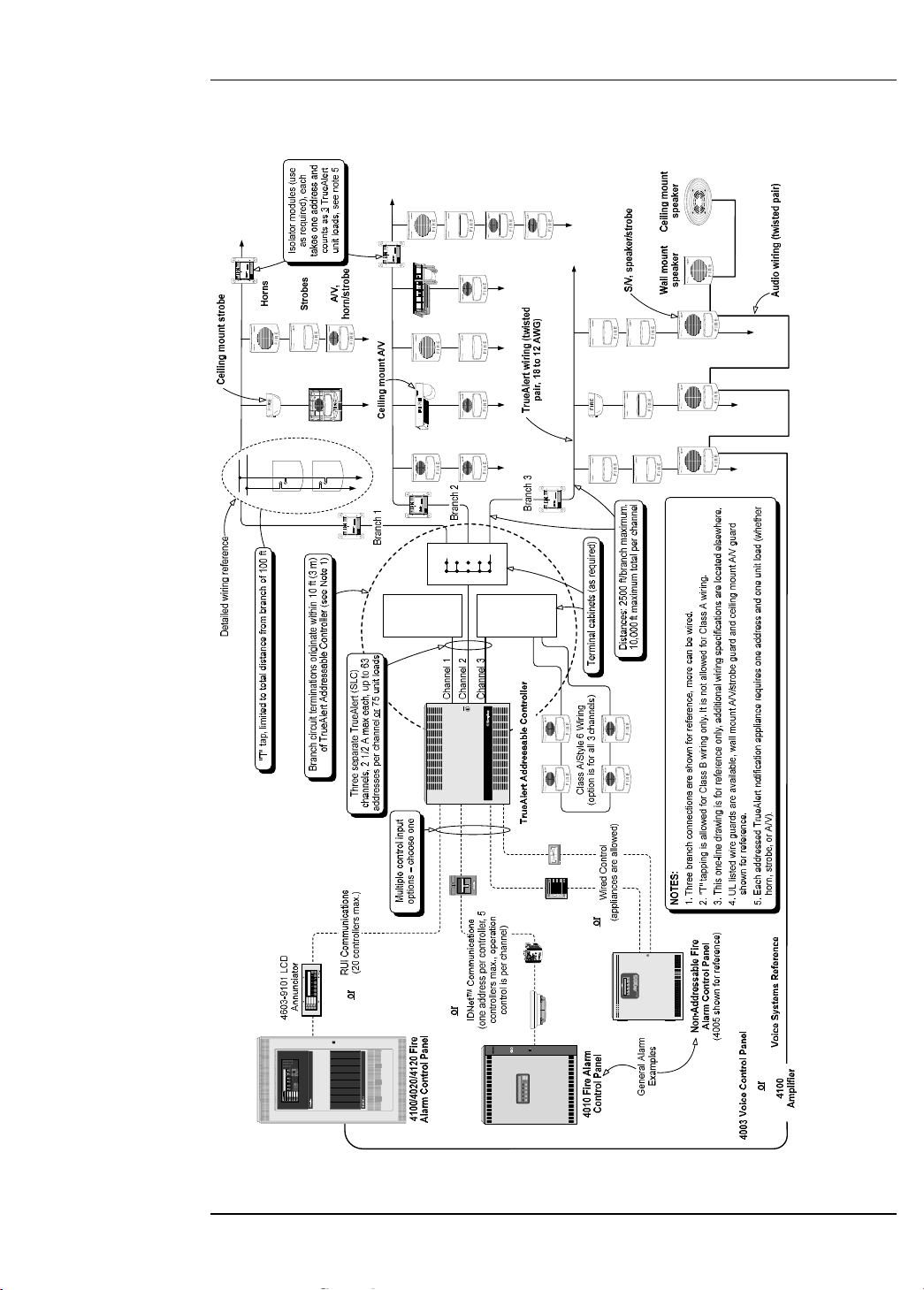
Figure 2-1 summarizes the connections between the 4009 TrueAlert Addressable Controller,
FACPs, and peripheral appliances. The figure shows example connections. Refer to 842-158 Field
Wiring Diagram for instructions.
**SYSTEM IS NO RM AL**
12:02:15pm Fri 19-Feb-99
ALARM
ACK
SUPV
ACK
TROUBLE
ACK
ALARM
SILENCE
SYSTEM
RESET
FIRE
ALARM
SYSTEM
SUPERVISORY
SYSTEM
TROUBLE
ALARM
SILENCED
AC
POWER
FIRE ALARM
CONTRO L
DISCO NNEC
POW ER BEF
SERVICING
CAUTIO N
** SYSTEM I S NO RM AL * *
12:02:15pm Mon 8-Mar-99
SUPV
ACK
SYSTEM
SUPERVISORY
ALARM
ACK
FIRE
ALARM
TROUBLE
ACK
SYSTEM
TROUBLE
ALARM
SILENCE
ALARM
SILENCED
SYSTEM
RESET
AC
POW ER
POWER
BEFORE
SERVICING
CAUTION
DISCONNECT
Tru eAlert Addr essable Contr oller
TM
Simplex Time Recorder Co.
Gardner, MA 01441
ON
ADDRESS
MSB
4905-9929 TRUEALERT ISOLATOR
INST. INSTR. 574-769 REV
RELAY CONTACTS
3 AMP, 30 VDC
MODULE
15 mA MAX 24 VDC
576-733
PORT 1
+ -
PORT 2
+ -
Simplex Time Recorder Co.
Gardner, MA 01441
ON
ADDRESS
MSB
4905-9929 TRUEALERT ISOLATOR
INST. INSTR. 574-769 REV
RELAY CONTACTS
3 AMP, 30 VDC
MODULE
15 mA MAX 24 VDC
576-733
PORT 1
+ -
PORT 2
+ -
FIRE
ALARM
ALARM
SILENCED
PRIORITY 2
ALARM
SYSTEM
SUPERVISORY
SYSTEM
TROUBLE
POWER
ON
ALARM
ACK
SUPV
ACK
TBL
ACK
ALARM
ACK
ALARM
SILENCE
SYSTEM
RESET
DISPLAY
TIME
SYSTEM IS NORMAL
12:35:15 am MON 22 NOV 99
ALARMFIRE
PULL DOWN
-
I
D
N
E
T
I
N
+
+
I
D
N
E
T
I
N
-
Simplex Time Recorder Co.
Gardner, MA 01441
ON
ADDRESS
MSB
4905-9929 TRUEALERT ISOLATOR
INST. INSTR. 574-769 REV
RELAY CONTACTS
3 AMP, 30 VDC
MODULE
15 mA MAX 24 VDC
576-733
PORT 1
+ -
PORT 2
+ -
Simplex Time Recorder Co.
Gardner, MA 01441
ON
ADDRESS
MSB
4905-9929 TRUEALERT ISOLATOR
INST. INSTR. 574-769 REV
RELAY CONTACTS
3 AMP, 30 VDC
MODULE
15 mA MAX 24 VDC
576-733
PORT 1
+ -
PORT 2
+ -
Simplex Time Recorder Co.
Gardner, MA 01441
ON
ADDRESS
MSB
4905-9929 TRUEALERT ISOLATOR
INST. INSTR. 574-769 REV
RELAY CONTACTS
3 AMP, 30 VDC
MODULE
15 mA MAX 24 VDC
576-733
PORT 1
+ -
PORT 2
+ -
FIRE
Fire Control
Figure 2-1. 4009 TrueAlert Applications Diagram
System Overview: Applications Diagram
Illustration
Page 21
2-3
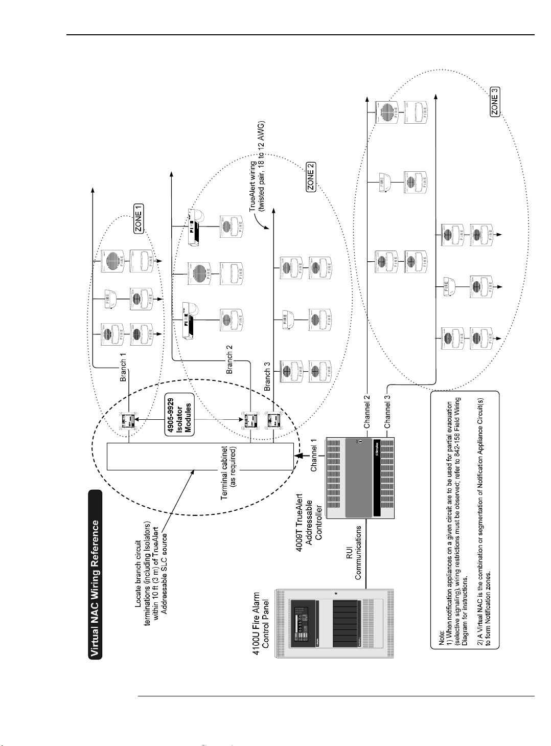
Figure 2-2 shows that selective signaling can only be done with an RUI connection to a 4100U fire Alarm Control
Panel.
Simplex Time Recorder Co.
Gardner, MA 01441
ON
ADDRESS
MSB
4905-9929 TRUEALERT ISOLATOR
INST. INSTR. 574-769 REV
RELAY CONTACTS
3 AMP, 30 VDC
MODULE
15 mA MAX 24 VDC
576-733
PORT 1
+ -
PORT 2
+ -
Simplex Time Recorder Co.
Gardner, MA 01441
ON
ADDRESS
MSB
4905-9929 TRUEALERT ISOLATOR
INST. INSTR. 574-769 REV
RELAY CONTACTS
3 AMP, 30 VDC
MODULE
15 mA MAX 24 VDC
576-733
PORT 1
+ -
PORT 2
+ -
Simplex Time Recorder Co.
Gardner, MA 01441
ON
ADDRESS
MSB
4905-9929 TRUEALERT IS O LAT OR
INST. INSTR. 574-769 REV
RELAY CONTACTS
3 AMP, 30 VDC
MODULE
15 mA MAX 24 VDC
576-733
PORT 1
+ -
PORT 2
+ -
Fire Control
POWER
BEFORE
SERVICING
CAUTION
DISCONNECT
TrueAlert Addressable Controller
TM
Figure 2-2. Selective Signaling Example
System Overview: Selective Signaling
Illustration
Page 22

2-4
This section describes how to use the DIP switches on the 4009 TrueAlert Addressable Controller
board for setting addresses and optional features.
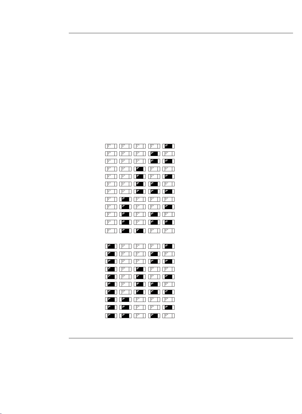
The SLC Appliance Switches (SW1, SW2, SW3) are 8-position DIP switches. Use these switches
to set the number of appliances connected to each SLC. SW1 corresponds to SLC 1, SW2
corresponds to SLC 2, and SW3 corresponds to SLC 3. A maximum of 63 appliances or 2.5 amps
of power may be specified per SLC channel (refer to Field Wiring Diagram 842-158). Refer to
Figure 1-2 to locate the switches on the system board. Refer to Figure 2-2, below, to specify the
correct number of appliances for each SLC channel.
Use a small screwdriver or pen to set the switches.
Notes:
• DIP switch in “1” position is ON while DIP switch in “0” position is OFF.
• SW1, SW2, and SW3 are disabled when the RUI host interface is selected.
0000 1000 0100 1100
0000
0 163248
1000
1 173349
0100
2 183450
1100
3 193551
0010
4 203652
1010
5 213753
0110
6 223854
1110
7 233955
0001
8 244056
1001
9 254157
0101
10 26 42 58
1101
11 27 43 59
0011
12 28 44 60
1011
13 29 45 61
0111
14 30 46 62
15 31 47 63
LSB
MSB
1 2345678
1111
DIP SWITCHES 5 AND 6
DIP
SWITCHES
1 THRU 4
RESERVED FOR
FUTURE USE
NOT USED
ON
OFF
1 = ON 0 = OFF
DIPSWITCH IS SHOWN
SET AT ADDRESS 7.
Figure 2-3. SLC Appliance Settings (SW1, SW2, SW3)
Continued on next page
System Configuration
Overview
SLC Appliance DIP
Switches
(SW1, SW2, SW3)
DIP SWITCH IS SHOWN
SET AT ADDRESS 7.
Page 23

2-5
The 8-position Hardware Configuration DIP Switch (SW4) is used to configure what hardware is
present and supervised by the Addressable Controller, and how the hardware is used. The
Hardware Configuration Switch is located to the right of the channel indicator LEDs
(E-A indicators) on the system board (see Figure 1-2).
Table 2-1, below, lists the SW4 settings.
IMPORTANT: All settings, including “N/A,” will reinitialize the TrueAlert
Addressable Controller.
Table 2-1. Hardware Configuration Switch (SW4)
Switch
Number
Setting
IDNet/Hardwired Selection RUI Selection
OFF, OFF Normal Operation
ON, OFF Global Silent Appliance Test
OFF, ON Manual Real Appliance Test
1, 6
ON, ON Manual Silent Appliance Test
OFF No Class A Adapter Card Present
2
ON Class A Adapter Card Present
N/A
OFF, OFF RUI Host RUI Host
ON, OFF IDNet Host N/A
OFF, ON Reserved
3, 4
ON, ON Dual NAC Host
OFF No IDNet Repeater Card Present
5
ON IDNet Repeater Card Present
N/A
6 See first row of table
OFF Appliance Blink on Poll Disabled
7
ON Appliance Blink on Poll Enabled
OFF Horn Volume: Low
8
ON Horn Volume: High
N/A
Normal Operation. The Addressable Controller runs under normal operation only when both
switches 1 and 6 are set of OFF. Any other combination between the two switches puts the
Addressable Controller into one of the test modes described below and on the next page.
Global Silent Appliance Test. Sets all TrueAlert notification appliances so that alarms are
silent. If the system goes into alarm, appliances will illuminate their LEDs in a Steady On state
without audibles or strobes.
Continued on next page
System Configuration, Continued
Hardware
Configuration DIP
Switch (SW4)
Page 24

2-6
Manual Real Appliance Test. Activates a test mode so that appliances can be manually tested
one at a time. The manual real appliance test makes a given notification appliance report its
address and emits an alarm. Place a magnet on the appropriate area of the notification appliance to
initiate a real appliance test. The LED emits one long flash denoting the test acknowledge signal,
and then another long flash denoting the first digit (always zero) of the appliance address. The
LED then flashes one to six times to denote the second digit of the address, pauses, and flashes
one to nine times to indicate the third digit of the address. A zero is always indicated by one long
flash. After the LED flashes, the appliance goes into alarm for 2 to 3 seconds.
Manual Silent Appliance Test. Like the real appliance test mode, this allows appliances to be
manually tested, one at a time. The manual silent appliance test makes a given notification
appliance report its address without emitting an alarm. Place a magnet on the appropriate area of
the appliance to initiate a silent appliance test. The LED emits one long flash denoting the test
acknowledge signal, and then another long flash denoting the first digit (always zero) of the
appliance address. The LED then flashes one to six times to denote the second digit of the address,
pauses, and flashes one to nine times to indicate the third digit of the address. A zero is always
indicated by one long flash. When the address is done, the LED illuminates once more for 2 to 3
seconds.
Class A Adapter Card Options. Refer to Table 2-2, below, for a description of what happens
when switch 2 is set.
Note: In Table 2-2, “Yes” denotes the Class A Option Card has been correctly wired and
installed in the Addressable Controller.
Table 2-2. (SW4) Switch 2
(SW4) Switch 2
Setting
Class A Card Connected
to Addressable
Controller?
System Status
Yes Normal
ON
No Class A Trouble*
Yes Configuration Mismatch Trouble
OFF
No Normal
*In Hardwired mode, this condition clears once a Class A Card is correctly installed and the Addressable
Controller is reinitialized. In the 4010 and 4100, the message clears only after the Class A Card is correctly
installed and the SYSTEM RESET button is pressed at the host panel.
RUI Host. Selected when the TrueAlert Addressable Controller is used with a 4100 or 4020
FACP. The Addressable Controller LEDs will display a Comm Trouble if the RUI channel is not
connected.
IMPORTANT: The Addressable Controller cannot be connected to hardwired NAC
channels (TB7) and a RUI host (TB1) at the same time.
Continued on next page
System Configuration, Continued
Hardware
Configuration DIP
Switch (SW4),
continued
Page 25

2-7
IDNet Host. Selected when the TrueAlert Addressable Controller is used with a 4010 FACP.
IMPORTANT:
• The Addressable Controller cannot be connected to hardwired NAC
channels (TB7) and an IDNet host (TB2) at the same time. Make sure only
one interface is selected (IDNet, RUI, or Hardwired).
• The Addressable Controller LEDs do not indicate a trouble if the IDNet
channel is disconnected. The only trouble indication is at the host panel.
Dual NAC Host. Selected when the Addressable Controller is hardwired to the host FACP using
TB7 on Figure 1-2. The Addressable Controller can be hardwired to any compatible FACP.
IMPORTANT:
• The Addressable Controller cannot be connected to a RUI host (TB1) or an
IDNet host (TB2) while it is connected to hardwired NAC channels (TB7) at
the same time. Make sure only one interface is selected.
• The Addressable Controller LEDs do not indicate a trouble if the hardwired
channels are disconnected. The only trouble indication is at the host panel.
IDNet Repeater Card Options. Refer to Table 2-3, below, for a description of what happens
when Switch 5 is set.
Note: In Table 2-3, “Yes” denotes the IDNet Repeater Card has been correctly wired
and mounted to the Addressable Controller.
Table 2-3. (SW4) Switch 5
(SW4) Switch 5
Setting
IDNet Repeater Card
Connected to
Addressable Controller?
System Status
Yes Normal
ON
No
Yes
Configuration Mismatch Trouble
OFF
No Normal
Appliance Blink on Poll Disabled. Stops notification appliance LEDs from blinking when the
appliances are polled during normal operation.
Appliance Blink on Poll Enabled. Forces notification appliance LEDs to blink whenever they
are polled (i.e., every few seconds). Note that a blinking LED at the appliance indicates that
polling was successful, and does not indicate whether the system detected a problem with the
appliance (the host panel must be used to determine appliance status).
Horn Volume: Low. Sets the horn volume at Low for all A/Vs and Horns connected to the
Addressable Controller. Horn volume is not configurable on an appliance-by-appliance basis.
Horn Volume: High. Sets the horn volume at High for all A/Vs and Horns connected to the
Addressable Controller. Horn volume is not configurable on an appliance-by-appliance basis.
Continued on next page
System Configuration, Continued
Hardware
Configuration DIP
Switch (SW4),
continued
Page 26

2-8
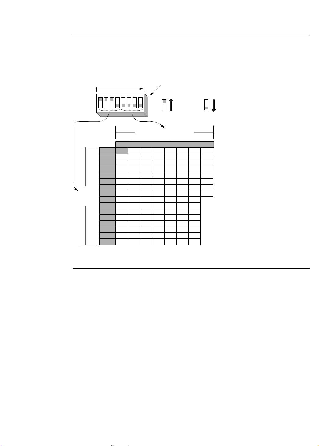
The Address/Software Configuration Switch (SW5) is an 8-position DIP switch. The
Address/Software Configuration Switch is located to the right of the Hardware Configuration
Switch (SW4) on the system board.
When the Addressable Controller is operating as an addressable IDNet or RUI peripheral, this
switch sets the Addressable Controller address. Set the Addressable Controller address using
Figure 2-3 (IDNet) or Figure 2-4 (RUI) as a reference.
When the Addressable Controller operates in a hardwired configuration (without addresses), this
switch is used to control the configuration as described in Table 2-1.
• The Addressable Controller can be assigned address number 1 through 250 in IDNet
interface mode. See Figure 2-3.
• The Addressable Controller can be assigned address number 1 through 119 in RUI
interface mode. See Figure 2-4.
Figure 2-3, below, applies to IDNet mode only.
Use a small screwdriver or pen to set the switches.
Note: DIP switch in “1” position is ON while DIP switch in “0” position is OFF.
0000 1000 0100 1100 0010 1010 0110 1110 0001 1001 0101 1101 0011 1011 0111 1111
0000
0 16 32 48 64 80 96 112 128 144 160 176 192 208 224 240
1000
1 17 33 49 65 81 97 113 129 145 161 177 193 209 225 241
0100
2 18 34 50 66 82 98 114 130 146 162 178 194 210 226 242
1100
3 19 35 51 67 83 99 115 131 147 163 179 195 211 227 243
0010
4 20 36 52 68 84 100 116 132 148 164 180 196 212 228 244
1010
5 21 37 53 69 85 101 117 133 149 165 181 197 213 229 245
0110
6 22 38 54 70 86 102 118 134 150 166 182 198 214 230 246
1110
7 23 39 55 71 87 103 119 135 151 167 183 199 215 231 247
0001
8 24 40 56 72 88 104 120 136 152 168 184 200 216 232 248
1001
9 25 41 57 73 89 105 121 137 153 169 185 201 217 233 249
0101
10 26 42 58 74 90 106 122 138 154 170 186 202 218 234 250
1101
11 27 43 59 75 91 107 123 139 155 171 187 203 219 235
0011
12 28 44 60 76 92 108 124 140 156 172 188 204 220 236
1011
13 29 45 61 77 93 109 125 141 157 173 189 205 221 237
0111
14 30 46 62 78 94 110 126 142 158 174 190 206 222 238
15 31 47 63 79 95 111 127 143 159 175 191 207 223 239
LSB
MSB
1 2345678
1111
DIP SWITCHES 5 THRU 8
ON
OFF
1 = ON 0 = OFF
251
252
253
254
255
DIPSWITCH IS SHOWN SET AT ADDRESS 7.
Figure 2-4. IDNet Address Settings (SW5)
Continued on next page
System Configuration, Continued
Address/Software
Configuration DIP
Switch (SW5)
DIP SWITCH IS SHOWN SET AT ADDRESS 7.
Page 27
2-9
Figure 2-4, below, applies to RUI mode only.
Use a small screwdriver or pen to set the switches.
Note: DIP switch in “1” position is ON while DIP switch in “0” position is OFF.
0000 1000 0100 1100 0010 1010 0110 1110
0000
0 163248648096112
1000
1 173349658197113
0100
2 183450668298114
1100
3 193551678399115
0010
4 2036526884100116
1010
5 2137536985101117
0110
6 2238547086102118
1110
7 2339557187103119
0001
8 2440567288104
1001
9 2541577389105
0101
10 26 42 58 74 90 106
1101
11 27 43 59 75 91 107
0011
12 28 44 60 76 92 108
1011
13 29 45 61 77 93 109
0111
14 30 46 62 78 94 110
15 31 47 63 79 95 111
LSB
MSB
1 2345678
1111
DIP SWITCHES 5 THRU 8
DIP
SWITCHES
1 THRU 4
ON
OFF
1 = ON 0 = OFF
DIPSWITCH IS SHOWN SET AT ADDRESS 7.
Figure 2-5. RUI Address Settings (SW5)
Continued on next page
System Configuration, Continued
Address/Software
Configuration DIP
Switch (SW5),
continued
DIP SWITCH IS SHOWN SET AT ADDRESS 7.
Page 28

2-10
When the 4009 operates as a non-addressable NAC extender, Switch SW5 configures the
operation of the output SLCs, based on the state of the two NAC control inputs. Refer to
Table 2-2 for SLC control operation settings.
Table 2-4. Software Configuration Settings for Hardwired Control (SW5)
Switch
Number
Setting Mode of Operation
1-3 Reserved
OFF Visuals Flash Once Per Second
4
ON Visuals Flash Temporal with Audibles
OFF, OFF
Temporal Audibles
ON, OFF March Time Audibles
OFF, ON Fast March Time Audibles
5, 6
ON, ON Audibles Steady On
7 Reserved
OFF
Channel 1 Controls All Visibles
Channel 2 Controls All Audibles
8
ON
Channel 1 Controls All Appliances on SLC 1
Channel 2 Controls All Appliances on SLCs 2 and 3
System Configuration, Continued
Address/Software
Configuration DIP
Switch (SW5),
continued
Page 29

2-11
IMPORTANT: Notify the appropriate personnel (building occupants, fire
department, monitoring facility, etc.) of the installation.
The following sections contain installation information which is applicable to the 4009 TrueAlert
Addressable Controller. Be sure that you are thoroughly familiar with this information before
installing the 4009 TrueAlert Addressable Controller.
To help you with installation of this and other Simplex Fire Alarm equipment, use How to Wire a
Building for a Fire Alarm System (FA2-91-001 or 575-892) for general reference.
The following tools and equipment are required to install the 4009 TrueAlert Addressable
Controller:
• 1/4-inch flat-tip screwdriver (Phillips screwdriver optional)
• 1/8-inch flat-tip screwdriver
• Volt-Ohmmeter
• Diagonal cutting pliers
• Wire strippers
Continued on next page
System Installation
General Information
Tools and
Equipment Required
Page 30

2-12
The following documentation may be required:
• Field Wiring Diagram 842-158
• 4009-9812 Class A Adapter Option Card Installation Instructions (574-763)
• 4009-9809 IDNet Repeater Option Card Installation Instructions (574-327)
• 4009-9810/-9811 Fiber Optic Link Option Installation Instructions
(574-182)
• 4901 TrueAlert Horn Installation Instructions (574-764)
• 4902 TrueAlert Ceiling-Mount and Wall-Mount Speaker Installation Instructions
(574-765)
• 4903 TrueAlert Ceiling-Mount A/V Installation Instructions (574-929)
• 4903 TrueAlert S/V Installation Instructions (574-766)
• 4903 TrueAlert A/V Installation Instructions (574-768)
• 4904 TrueAlert Ceiling-Mount Strobe Installation Instructions (574-928)
• 4904 TrueAlert Strobe Installation Instructions (574-767)
• 4905 TrueAlert Isolator Module Installation Instructions (574-769)
• 4906 TrueAlert Multi-Candela Notification Appliances Installation Instructions
(579-808)
• 4906 TrueAlert Multi-Candela Amber Strobe Installation Instructions (579-828)
• All wiring must be installed in accordance with local codes.
• A minimum of 6 inches (15.24 cm) of free conductor is required at each electrical box to
facilitate terminations.
• A 12-inch (30.48 cm) service loop of cable is required for all continuous pulls through an
electrical box.
• All system wiring subject to physical damage must be mechanically protected based on
the environment to which the cable is subjected.
• A neatly wired system helps assure an accurate inspection of all connections and simplify
troubleshooting.
• Field adjustments may not be made to the TrueAlert Addressable Controller board.
Continued on next page
System Installation, Continued
Required
Documentation
General Notes
Page 31

2-13
A
Use the following procedure when mounting a TrueAlert Addressable Controller.
CAUTION: Read all instructions carefully before cutting conduit/service entrances
and installing back box. Failure to comply with all installation
requirements may result in a violation of UL or FCC regulations.
1. Lay the TrueAlert Addressable Controller on a flat surface.
2. Unlock and open the panel door. Disconnect the AC wiring harness from the card cage.
Remove the electronic card cage assembly and store it in a safe, dry area.
3. Determine the amount and proper location of conduit/service entrances (see Figure 2-5).
Make all appropriate entrances into the back box. Power limited and non-power limited
wiring must enter through separate conduit/service entrances. AC power entrance into the
back box is recommended at the bottom right side of the back box.
Note: Maximum intrusion into back box for conduit is ½ inch (1.27 cm).
Recommended Conduit Locations
Locate conduit entry approximately where shown.
A. Class B or Class A Fiber Feed and AC Power
B. Signaling Line Circuits, IDNet and RUI
C. IDNet, RUI, or Class A Fiber Return
D. SLCs, NACs, IDNet, and RUI or Class A Fiber Return
E. Control Inputs: IDNet, RUI, or Notification Appliance Circuits
Figure 2-6. Installing the 4009 Back Box
Continued on next page
System Installation, Continued
Mounting the 4009
TrueAlert
Addressable
Controller
B
BATTERY
MOUNTING
AREA (NO
CONDUIT
ENTRY)
KNOCKOUT
SCREW/NAIL
HOLES for
SEMI-FLUSH
MOUNTING
TOP VIEW
NON-POWER LIMITED WIRING ONLY
C
D
E
A
Page 32

2-14
4. Mount the back box to the wall so that the top of the enclosure is no more than eight feet
above the floor. The back box must be level and plumb. For surface mounting, use the
teardrop and clearance holes located in the rear of the box and screw to wall.
5. Wire non-power limited wiring in the shaded areas only (see Figure 2-5), this includes AC
input and battery connections. All other wiring is power limited. Maintain at least ¼-inch
(0.63 cm) spacing between all power limited and non-power limited wiring.
6. Connect the AC wiring harness and install the electronic card cage assembly to the 4009
cabinet.
When wiring the 4009 TrueAlert Addressable Controller, refer to Field Wiring Diagram
842-158, the 4009 TrueAlert Applications Diagram (Figure 2-1), and the following system wiring
requirements.
• All wiring, except incoming power and ground connecting wires, must be free from
grounds or shorts and have a resistance of one megohm, or higher, to earth.
• All wires are to be copper conductors only, except fiber cables. All equipment must be
installed in accordance with the manufacturer’s recommendations and the specifications
and standards of the Authority Having Jurisdiction (AHJ). The installation of all wiring,
cable, and equipment must be in accordance with NFPA 70 National Electrical Code.
• If shielded wire is used, the metallic continuity of the shield must be maintained and
insulated throughout the entire length of the cable. The entire length of the cable must
have a resistance greater than one megohm to earth.
• Splicing is permitted in accordance with NFPA 70 National Electrical Code. All wiring
must be terminated with UL listed appliances (e.g., wire nuts, pressure connectors).
Wiring terminated with only electrical tape is not permitted. All splicing (free ends of
conductors) must be covered with an insulation equivalent to that of the conductors.
• An appropriate system ground must be provided for earth detection and lightning
protection appliances. The connection must be an approved dedicated earth connection
per NFPA 70 National Electrical Code.
• When running wires to the 4009, identify the wires appropriately. Only system wiring
can be run in the same conduit which includes SLC wiring, NAC wiring, IDNet wiring,
RUI wiring, 24 V AUX wiring, and FACP speaker circuits.
• Input power and external battery power are non-power limited and cannot be run
with power limited system wiring.
IMPORTANT: If the 4009T is powered up with zero devices connected, the 4009T will
indicate channel failure for those channels that are programmed to support
devices. The 4009T will not sense devices as they are connected when the
4009T has been powered up with zero devices connected. After at least one
valid device is connected, the unit must be reset by toggling dipswitches on
Hardware Configuration Switch SW4 (SW4-2 for example) and then the
4009T will communicate with devices as they are added.
Continued on next page
System Installation, Continued
Mounting the 4009
TrueAlert
Addressable
Controller, continued
Wiring the 4009
TrueAlert
Addressable
Controller
Page 33

2-15
AC Input - 120VAC, 3 amperes, 60Hz
Battery Input - 24VDC, 8 amperes
4009 TRUEALERT
ADDRESSABLE
CONTROLLER
(SEE
NOTE 2)
AC INPUT
POWER
EXTERNAL
BATTERY
CONNECTION
(IF REQUIRED)
IDNet
INPUT
RUI
INPUT
TO AUDIBLE AND/OR VISIBLE
NOTIFICATION APPLIANCES
TRUEALERT CHANNEL
SIGNALING LINE CIRCUITS:
THREE CLASS B/STYLE 4 CIRCUITS STANDARD
(CLASS A/STYLE 6 CIRCUITS AVAILABLE)
CIRCUITS RATED AT
2 1/2A @ 24 VDC PER CIRCUIT,
POWER LIMITED 8A TOTAL POWER AVAILABLE
#18 AWG MIN
NAC OF
HOST FACP
HARDWIRED
NAC
CONTROL
AUXILIARY
POWER
OUTPUT
Notes:
1. Refer to the Field Wiring Diagram (842-158) for detailed information on 4009 System Wiring
Configurations.
2. External Battery requires splicing into existing Battery Harness (733-945), see Note 1.
Figure 2-7. 4009 TrueAlert Addressable Controller Connection Diagram
Continued on next page
System Installation, Continued
System Power
Requirements
Page 34

2-16
Refer to Field Wiring Diagram 842-158 for detailed information and the installation instructions
for each appliance during peripheral appliance installation. The procedure listed below is a
general outline for installing the 4009 peripheral appliances.
1. Determine the mounting locations of the peripheral appliances and install system wires from
the mounting location of each peripheral appliance to the 4009 system board. All wiring must
be minimum 18 AWG, supervised, and power limited.
2. Install all peripheral appliances and connect them to appropriate wires. (Refer to the
installation instructions packed with the appliances.)
System Installation, Continued
Mounting and Wiring
Peripheral
Appliances
Page 35

2-17
The 4009 TrueAlert Addressable Controller supports several option add-on cards:
4009-9812 Class A Adapter Option Card. Allows fault tolerance in the case of open circuit
wiring faults. One card provides Class A/Style 6 functionality for three TrueAlert SLCs. See
4009-9812 Class A Adapter Option Card Installation Instructions (574-763).
4009-9809 IDNet Repeater Option Card. Regenerates and provides a power and distance
boost for the IDNet channel. Takes the IDNet signal from the 4009 receiver and retransmits it on
its output side at host panel IDNet levels. See IDNet Repeater Option Card Installation
Instructions (574-327).
4009-9810/-9811 Fiber Optic Receiver Option Card. Works with the IDNet Fiber
Transmitter to form a fiber optic link from an IDNet channel to a remote TrueAlert Addressable
Controller. The fiber optic link allows remote buildings (within 3,000 ft (914.4 m)) to connect to
the IDNet channel, and to minimize susceptibility to electrical transients. See Fiber Optic Link
Option Installation Instructions (574-182).
Connectors are provided on the base assembly of the 4009 system board to support the available
option cards. Optional hardware must be configured with the Hardware Configuration DIP
Switch (SW4), described in Table 2-1 on page 2-4, for proper system operation.
Installing Option Interfaces
Overview
Page 36

Page 37

3-1
The 4009 TrueAlert Addressable Controller can be configured to work with the 4010 via
programming at the 4010 panel.
The panel programmer has the capability of auto-detecting new hardware, so that a 4009
TrueAlert Addressable Controller can be added to an existing configuration. Alternatively, the
panel programmer can be used to manually add the 4009 TrueAlert Addressable Controller to the
system setup. This chapter describes both methods.
The table below lists the topics in this chapter.
Topic See Page
4010 Programming Steps 3-2
Deleting the 4009 TrueAlert Addressable Controller 3-6
4010 Quick CFIG 3-7
Chapter 3
4010 Panel Programming
Overview
In this Chapter
Page 38

3-2
Each step in this section is intended to be read sequentially, so that the last instruction from
“Step 1. Starting the Programmer,” for example, leads directly to the first instruction in
“Step 2. Adding an IDNet Point…” Read the entire section to make sure you make all the
necessary configurations.
These programming instructions can be used to:
• Add a 4009 TrueAlert Addressable Controller to a 4010
• Modify settings for already programmed 4009 TrueAlert Addressable Controllers
The instructions below describe how to log in and start the 4010 panel programmer.
1. Press the MENU button so that the display reads Menu:[Control/View Points].
Then press the NEXT button. The display reads Menu:[Login/Logout].
2. Press the ENTER button. The display reads <Enter> to [Login]. Press ENTER
again.
3. The display reads Passcode:[0]. Enter your passcode. The passcode must have
access to programming and all other menus mentioned in these instructions. Use the
PREVIOUS and NEXT buttons to select numbers 0 through 9. When you have selected
the correct number, use the right arrow button to move to the next digit. When you move
to a different digit, numbers that have already been entered will appear as asterisks (*). If
you make an error, use the left arrow button to backspace. When you are done, press
ENTER. At this point the display reads **Login is Accepted** and displays your
current access level.
4. When the display returns to normal, press NEXT until you reach
Menu: [Programming]. Press ENTER.
5. The display reads Please Wait… Fire Alarm Operation Suspended. After
a moment, it reads Press <ENTER> for Programming Press <EXIT> to
resume operation. Press ENTER.
Continued on next page
4010 Programming Steps
Overview
Step 1:
Starting the
Programmer
Page 39

3-3
Use the following instructions to add a 4009 IDNet point for the 4009 TrueAlert Addressable
Controller.
1. From the Programming: [Configure Points] menu item, press ENTER.
2. Press NEXT until the Configure Point: [ZAMS/IAMS/RIAMS] menu item comes up.
Press ENTER.
3. The IDNet: [Add IDNet Point] menu item appears. Press ENTER.
4. The display now reads IDNet Device: M1-x where x is the first available IDNet address.
If needed, use the PREVIOUS or NEXT buttons to scroll through the addresses. Press
ENTER on the address to which you want to add the 4009 TrueAlert Addressable
Controller.
5. You now have to tell the 4010 that the IDNet device type will be a 4009. Press ENTER
on the menu item Point Label Function: [Edit Device Type]. When the display reads
Point Label: [PHOTO], use the PREVIOUS key to scroll to the appropriate device type.
The 4010 sees a 4009 TrueAlert Addressable Controller as a 4009 IDNet NAC Extender.
This means only the 4009 IDNet NAC Extender is available on the list of device types.
There are four 4009 IDNet NAC Extender device types, and only two that you can use.
Press ENTER on one of the following:
• [4009A (4 NAC)]. Normally used for the 4009 IDNet NAC Extender, this also
denotes the 4009 TrueAlert Addressable Controller.
• [R4009A (4 NAC)]. Normally used for the 4009 IDNet NAC Extender with
Repeater Option, this also denotes the 4009 TrueAlert Addressable Controller with
Repeater Option.
Note: [4009A (8 NAC)] and [R4009A (8 NAC)] cannot be used for the 4009
TrueAlert Addressable Controller.
6. When prompted, press ENTER to confirm your selection. The display reads
** Operation Complete **, and you are returned to the
IDNet Device: M1-x display, which shows the next available IDNet address. Note
that if you press the PREVIOUS button, the address you just configured has disappeared
because it is now being used.
7. At this point, repeat steps 4 through 6 for each 4009 TrueAlert Addressable Controller
you need to add. A total of five can be used. When you are done, press EXIT twice so
that the display reads Configure Point: [ZAMS/IAMS/RIAMS].
Continued on next page
4010 Programming Steps, Continued
Step 2:
Adding an IDNet
Point for the 4009
TrueAlert
Addressable
Controller
Page 40

3-4
1. Press NEXT until the Configure Point: [NACs] menu item appears. Press ENTER.
2. The display reads NAC Circuit: SIG 1 with a point type of Signal Circuit.
Press NEXT or PREVIOUS until IDNET M1-x: 4009A NAC 1 with a point type of
Signal Circuit appears. Press ENTER.
3. The Function: [Edit Device Type] menu item appears. Press NEXT so that
Function: [Edit Point Type] comes up. Press ENTER.
4. The display now reads [SSIGNAL: Fire Signal (On Til Silence)]. This is
only one of the available point types. Press PREVIOUS to display other point types.
Press ENTER on one of the two point types that apply to 4009 SLCs:
• [QALERT: TrueAlert Non Adr. (Gen)]. Makes the SLC respond to
Custom Control commands.
• [SQALERT: TrueAlert N.A. Horn(On Til Sil)]. Makes the SLC
respond to normal system control.
5. When prompted, press ENTER to confirm your selection. The display reads
** Operation Complete **, and you are returned to the
Configure Point: [NACs] display.
6. At this point, repeat steps 1 through 5 for each 4009 TrueAlert Addressable Controller
you need to add.
1. From the Configure Point: [NACs] menu item, scroll up to the
4009 NAC points you just modified. Each one displays an M1-x address and reads
TrueAlert N.A.NAC under it. Press ENTER on the first SLC point you want to edit.
2. The Function: [Edit Device Type] menu item comes up. Press NEXT until
the display reads Function: [Edit Point Label], and then press ENTER.
3. The part of the display that says IDNet M1-x: 4009A NAC 1 is now editable. Use
the PREVIOUS and NEXT buttons to select alphanumeric characters. When you have
selected the correct character, use the right and left arrow buttons to move to other
characters. When you are done, press ENTER and then press ENTER again to confirm
your selection. The display will then read **Operation Complete**.
4. Repeat steps 1 through 3 for every 4009 TrueAlert SLC.
5. Change IDNet M1-x: 4009A NAC 1 to say “4009T COMMON CLASS A
TROUBLE”.
Note: An alternate way to edit labels is to clear the point label completely and then
add text. To do this, press ENTER on the Configure Point: [NACs]
menu item, use the NEXT or PREVIOUS buttons to scroll to the
Function: [Clear Point Label] item, press ENTER, select an
IDNet M1-x entry, and press ENTER again. This deletes all the characters
on the top line of the display and lets you enter and save text as described in
step 3.
6. Press EXIT to return to Programming: [Configure Points].
Continued on next page
4010 Programming Steps, Continued
Step 3:
Configuring 4009
SLC Point Types
Step 4:
Editing Point Labels
Page 41

3-5
1. Press NEXT until you get to Programming: [Save CFIG], and press ENTER. Press
ENTER again at the prompt.
2. The display indicates the panel is saving and then restoring the CFIG and the labels.
When the system is done saving, it reboots. Your passcode is cleared from the system,
and you have to log in again if you want to continue programming (i.e., to add, edit, or
delete points).
To set audible signal types for audible notification appliances,
1. Log in and open the Programming menu.
2. Press NEXT until the Programming: System Options menu item appears. Press
ENTER.
3. Press NEXT until System Options: TrueAlert Non Adr. Horn appears,
and press ENTER.
4. Use the NEXT and PREVIOUS buttons to scroll through the list of options for TrueAlert
Non-Addressable NACs (in this case, TrueAlert SLCs) that appear in the New: field.
The choices are Temporal, Steady, and Slow March. When you make your
selection, press ENTER. Press ENTER a second time to confirm your choice.
4010 Programming Steps, Continued
Step 5:
Saving a
Configuration
Step 6:
Specifying Signal
Operation
Page 42

3-6
To delete a 4009 TrueAlert Addressable Controller from the list of device types from the
Programming menu:
1. From the Programming: [Configure Points] menu item, press ENTER.
2. Press NEXT until the Configure Point: [ZAMS/RIAMS/IAMS] menu item
comes up. Press ENTER.
3. Press PREVIOUS until you reach the IDNet: [Delete IDNet Point] menu
item. Press ENTER.
4. The display now reads IDNet Device: M1-x where x is the first available IDNet
address. If needed, use the PREVIOUS or NEXT buttons to scroll through the addresses.
Press ENTER on the address you want to delete.
5. Press ENTER again to verify your selection. The display reads
** Operation Complete ** when you are done.
Deleting the 4009 TrueAlert Addressable Controller
Overview
Page 43

3-7
The Quick CFIG option can be used instead of manual programming. Quick CFIG automatically
detects new hardware, and assigns default settings which you can modify later by using the
programmer manually.
To add one or more 4009 TrueAlert Addressable Controllers using Quick CFIG:
1. Press the MENU button, and then press NEXT until the display reads Menu: [Quick CFIG].
Press ENTER.
Note: The Quick CFIG menu item does not appear unless you have entered a valid
password with the appropriate access level. See “Step 1: Starting the
Programmer,” in this chapter.
2. The display reads Please Wait… Fire Alarm Operation Suspended. After
a moment, it reads Press <ENTER> for Programming. Press <EXIT> to
resume operation. Press ENTER.
3. The Quick CFIG: [Reconfigure All Hardware] menu item appears.
• If you are configuring a new job, press ENTER.
• If you are configuring an existing job, press NEXT so that
Quick CFIG: [Auto Detect NEW Hardware] comes up, and press ENTER.
4. Press ENTER at the prompt warning you that this will delete or change the existing
configuration.
5. Press ENTER once again to begin automatically detecting new hardware. The display
reads ** Detecting new Hardware **, and soon changes to
** Scanning for IDNet Devices **. After a few minutes, the display reads
Automatic Hardware Detection Completed, along with the number of
IDNet devices that were added. Finally, you are prompted to either press ENTER to go
back to the Quick CFIG menu, or EXIT.
• To go back to the Quick CFIG menu, press ENTER and skip the rest of the
instructions below.
• To stop programming and save your changes, press EXIT and continue to step 6.
6. The display notifies you that the configuration has changed, and prompts you to either
restore, save, or continue. Use the arrow buttons, and press ENTER on your selection.
• To save your latest changes, select Save and skip the rest of these instructions.
• To cancel your latest changes and restore the 4010 back to the previous
configuration, select Restore and skip the rest of these instructions.
• To go back to the previous screen, which allows you to enter the manual programming
menu, select Continue and refer to the “4010 Programming Steps” section.
7. From the Programming: [Configure Points] menu item, press NEXT until
the Configure Point: [NACs] menu item comes up. At this point, refer to
“Step 3: Configuring 4009 SLC Point Types” to set the correct point types. When you
finish “Step 3,” you will be done with the configuration. You can continue on to
“Step 4: Editing Point Labels,” or to “Step 5: Saving a Configuration.”
4010 Quick CFIG
Overview
Quick CFIG Steps
Page 44

3-8
Page 45

I-1
A
Addressable Controller, 1-1
block diagram, 2-2
deleting, 3-6
description, 1-3
hardwired interface, 1-4
IDNet interface, 1-3
mounting,
2-13
power requirements, 2-15
RUI interface, 1-3
system board illustration, 1-7
TrueAlert channels, 1-6
wiring, 2-14
Appliance Blink on Poll settings, 2-7
B
battery charger, 1-6
Blink on Poll settings, 2-7
C
Class A Adapter Option Card, 1-1
DIP switch settings, 2-6
D
DIP switch
address settings, 2-8
Appliance Blink on Poll settings, 2-7
Class A Adapter Option Card settings, 2-6
configuration for Addressable Controller, 2-10
Global Silent Appliance Test setting, 2-5
hardware configuration, 2-5
hardwired interface setting, 2-7
Horn volume settings, 2-7
IDNet interface setting, 2-7
IDNet Repeater Option Card setting, 2-7
Manual Real Appliance Test setting, 2-6
Manual Silent Appliance Test setting, 2-6
RUI interface setting, 2-6
SLC appliance addresses, 2-4
F
Fiber Optic Receiver Option Card, 1-1
G
Global Silent Appliance Test, 2-5
H
hardwired interface
description, 1-4, 1-5
DIP switch configuration settings, 2-10
DIP switch settings, 2-7
Horn volume settings, 2-7
I
IDNet interface
adding points, 3-3
address settings, 2-8
description, 1-3, 1-5
DIP switch settings, 2-7
point label programming, 3-4
point type programming, 3-4
Quick CFIG,
3-7
saving a configuration, 3-5
signal programming, 3-5
IDNet Repeater Option Card, 1-1
DIP switch setting, 2-7
installation
appliances, 2-16
Class A Adapter Option Card, 2-17
equipment needed,
2-11
Fiber-Optic Receiver Option Card, 2-17
IDNet Repeater Option Card, 2-17
mounting,
2-13
power requirements, 2-15
wiring, 2-14
L
LEDs
AC power, 1-10
Appliance Blink on Poll settings, 2-7
Earth Ground indication on, 1-10
Global Silent Appliance Test, 2-5
Manual Real Appliance Test, 2-6
Manual Silent Appliance Test, 2-6
trouble, 1-8
M
Manual Real Appliance Test, 2-6
Manual Silent Appliance Test, 2-6
mounting
Addressable Controller,
2-13
appliances, 2-16
N
notification appliances
overview, 1-2
P
panel programming (4010), 3-1
adding IDNet points, 3-3
deleting the Addressable Controller, 3-6
IDNet point labels, 3-4
IDNet point type, 3-4
Index
Page 46

point labels, 3-4
point types, 3-4
Quick CFIG, 3-7
saving, 3-5
signals, 3-5
starting up, 3-2
point label programming, 3-4
point type programming, 3-4
programming
4010 panel. See panel programming (4010)
Q
Quick CFIG, 3-7
R
Real Appliance Test, 2-6
related documentation, 2-12
RUI interface
address settings, 2-9
description, 1-3, 1-5
DIP switch settings, 2-6
S
saving a configuration, 3-5
signal programming
4010 (panel), 3-5
Silent Appliance Test
Global, 2-5
Manual, 2-6
SLC channels
on Addressable Controller, 1-6
overview, 1-2
T
trouble indicators, 1-8
Earth Ground, 1-10
TrueAlert Addressable Controller. See
Addressable Controller
TrueAlert channels
on Addressable Controller, 1-6
overview, 1-2
W
wiring
Addressable Controller, 2-14
appliances, 2-16
I-2
Page 47

Page 48

574-762
Rev. E
© 2005, 2007 Tyco Safety Products Westminster, Westminster, MA 01441-001 USA. Specifications and other information shown were current as of publication and are subject to change without notice.
 Loading...