

Simplex TrueAlert 4009 Series, TrueAlert 4009-9402CA, TrueAlert 4009-9401, TrueAlert 4009-9501 Operation Reference
R
TrueAlert Addressable Notification Reference
UL, ULC, CSFM Listed; FM Approved; TrueAlert Addressable Operation Reference &
MEA (NYC) Acceptance* 4009 Series TrueAlert Addressable Controller
Use for installed system expansion applications:
Refer to page 7 for appliance compatibility details
For new addressable notification fire alarm control panel
applications, refer to data sheet S4100-0100
TrueAlert Addressable Operation Features
4100ES Fire Alarm
Control Panel with TPS
TrueAlert addressable
notification appliances
or
TrueAlert
Isolator Module
1
5
+ 24V
ZONE PWR +
0V
2
6
ZONE PWR 3
7
+IDNET
IDC +
4
8
- IDNET
IDC -
5
1
6
2
7
3
SIMPLEX TIME RECORDER CO.
4090-9101
MONITOR ZAM, CLASS B
INSTAL. INSTR. 574-183
8
4
DATE CODE:
1
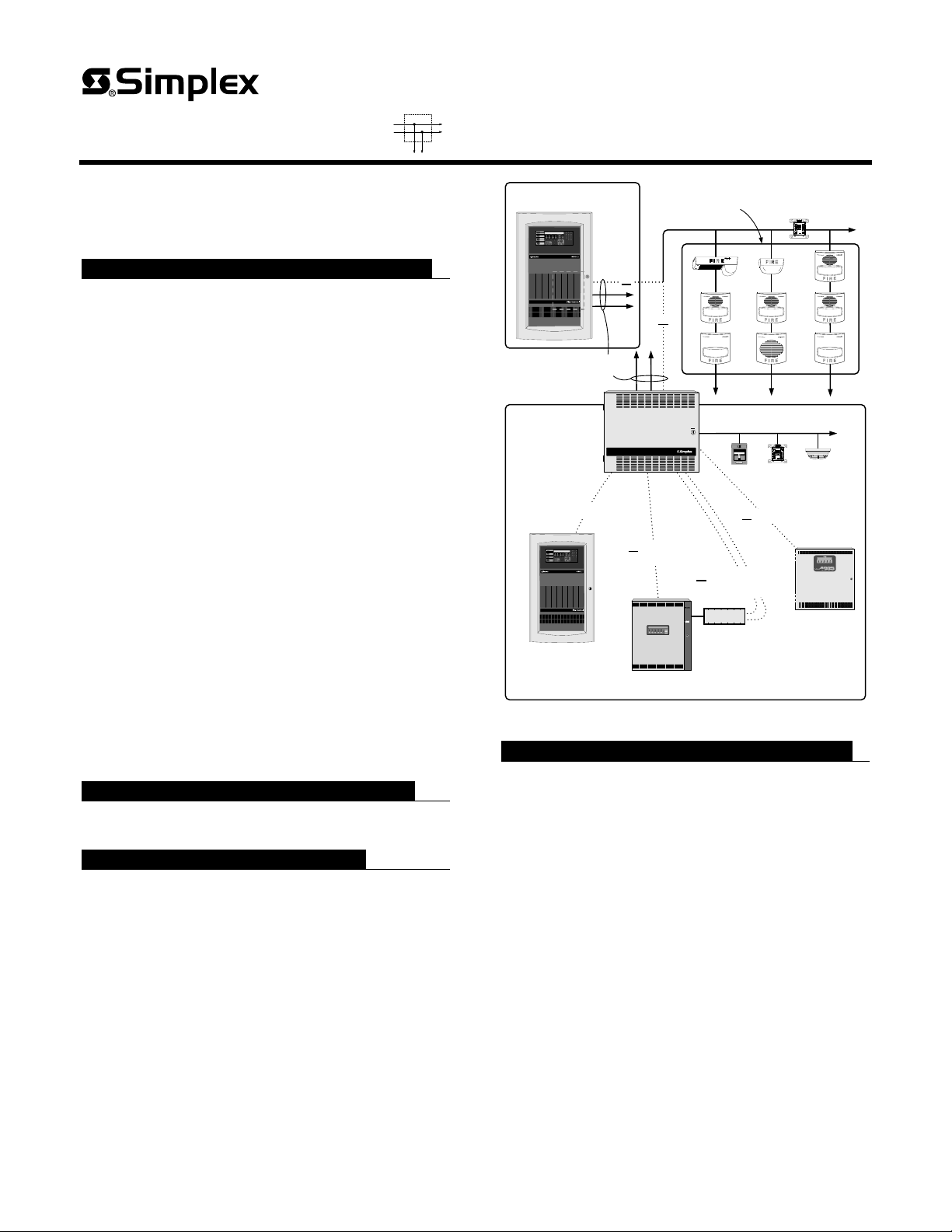
Each individually addressed notification appliance
receives power and control over a single wire pair
or
providing:
Supervised wiring connections to each appliance that
support using “T-tapped” wiring for Class B circuits
Three TrueAlert
SLC Channels
(Class A circuits require in/out wiring)
Horns sounding with selectable high or low output, as
Temporal 3 or March Time pattern (60 or 120 bpm), or
Steady On, controlled separately from visible appliances
on the same two-wire circuit
TrueAlert
Addressable
Controller
input options
TM
TrueAlert Addressable Controller
Optional IDNet Channel Repeater
CAUTION
DISCONNECT
POWER
BEFORE
SERVICING
1
5
+ 24V
ZONE PWR +
0V
2
6
ZONE PWR 3
7
+IDNET
IDC +
4
8
- IDNET
IDC -
ALARMFIRE
5
1
6
2
PULL DOWN
7
3
SIMPLEX TIME RECORDER CO.
4090-9101
MONITOR ZAM, CLASS B
INSTAL. INSTR. 574-183
8
4
DATE CODE:
1
Visible appliances operating synchronized at 1 Hz
Control over power limited, isolated output Signaling
Line Circuits (SLCs) with up to 63 addressable
appliances per SLC, and up to 189 appliances per control
source (refer to page 7 for detailed SLC ratings)
Control sources selectable to provide individual appliance
magnetic test mode and appliance LED polling indicator
4100ES, 4100U and 4010ES systems also provide
additional control capabilities using Virtual NAC
(VNAC) appliance groupings across SLCs and across
control sources
Class B, “T-tapped” wiring advantages:
Less wiring distance is required since traditional
end-of-line Class B wiring supervision is not needed
With less wiring distance required, voltage drops can be
RUI Communications
4100ES, 4100U, 4010ES,
4100, 4120, or 4020 Fire
Alarm Control Panel
or IDNet
Communications
** SYSTEM I S NORM AL **
12:02:15pm Mon 9-Feb-98
FIRE
SYSTEM
SYSTEM
ALARM
AC
ALARM
SUPERVISORY
TROUBLE
SILENCED
POWER
ALARM
SUPV
TROUBLE
ALARM
SYSTEM
ACK
ACK
ACK
SILENCE
RESET
4010 Fire Alarm
Control Panel
FIRE ALARM
CONTROL
CAUTION
DISCONNECT
POWER BEFO
SERVICING
or Wired Control
or Fiber Optic IDNet
Communications
IDNet Fiber
Optic Transmitter
Non-Addressable
Fire Alarm
Control Panel
TrueAlert Addressable Operation Reference Diagram
12:02:15pm Fri 19-Feb-99
FIRE
ALARM
ALARM
ACK
**SYSTEM IS NORMAL**
SYSTEM
SYSTEM
ALARM
SUPERVISORY
TROUBLE
SILENCEDACPOWER
SUPV
SYSTEM
TROUBLE
ALARM
ACK
RESET
ACK
SILENCE
reduced, allowing more appliances per wire run
UL listed to Standard 864*
TrueAlert Addressable Controllers (Contd.)
Extensive internal diagnostics include:
4100ES TrueAlert Power Supplies (TPS)
For mounting in 4100ES/4100U control panels:
Three, 3 A, SLCs (Special Application rating)
TrueAlert Addressable Controllers
Remote mounted control panel that provides:
Three, 2.5 A, SLCs (Special Application rating)
An 8 A power supply/battery charger for internal
batteries up to 12.7 Ah or up to 18 Ah in external cabinet
Multiple communications formats are available:
Remote Unit Interface (RUI) communications
from Simplex
®
4100ES/4010ES/4100U/4120/4100/4020
fire alarm control panels (4100U/4120/4100/4020
requires rev. 9 software or higher) assigns an address
point with custom label to each appliance for individual
trouble reporting
IDNet communications from Simplex 4010 fire alarm
control panels provide individual or multiple channel
control using a single IDNet address
Wired control from conventional NACs connects with
multiple options
S4009-0003-10 9/2015
LED status indicators that identify channel and trouble
Support for host fire alarm control panel WALKTEST
system test with IDNet or RUI communications**
Status monitoring of battery, input power, and earth
faults
Optional internal modules:
Class A Three Channel Adapter Module
IDNet Communications: Repeater or Fiber Optic
Receiver/Repeater; models for Class A or Class B
External accessories:
IDNet communication fiber optic transmitters
Remote TrueAlert communications isolator 4905-9929,
refer to data sheet S4905-0001 for details
External battery cabinet for 18 Ah batteries
* NOTE: Model 4009-9501 (240 VAC input) is not included in these listings. Refer to
page 2 for specific applicable listings by model. 4009-9401 (120 VAC input) has been
approved by the California State Fire Marshal (CSFM) pursuant to Section 13144.1 of the
California Health and Safety Code. See CSFM Listing 7310-0026:214 for allowable values
and/or conditions concerning material presented in this document. 4009-9401 is accepted
for use – City of New York Department of Buildings – MEA35-93E. Additional listings may
be applicable; contact your local Simplex product supplier for the latest status. Listings
and approvals under Simplex Time Recorder Co. are the property of Tyco Fire Protection
Products..

Introduction
TrueAlert addressable notification appliances are
individually addressed and receive power, supervision,
and control from a TrueAlert Signaling Line Circuit
(SLC). For wired control systems, strobe flashes and horn
outputs are synchronized per controller. For RUI and
IDNet communications control, controllers on the same
host control panel are synchronized. (Combination
RUI Communications Control (Continued)
Address points and custom labels are assigned to each
TrueAlert appliance allowing troubles to be reported
individually. Additionally, individual device types are
assigned and audible appliance coding types are selectable
for high or low output (~5 dBA difference) and with
operation as Temporal pattern, March Time pattern (60 or
120 bpm), or Steady On (continuous).
speaker/strobe TrueAlert appliances receive audible
control from separate audio circuit wiring.)
TrueAlert addressable operation allows strobes to
be wired onto the same two-wire SLC circuit as horns but
with separately controlled operation. Typical applications
are audible notification appliances activated as
“on-until-silenced” and visible notification appliances
activated as “on-until-reset.”
TrueAlert Addressable Controller diagnostics can
be implemented from the control panel including: Silent
or Active individual appliance magnet test, appliance
LED polling indication, or all appliance LEDs on.
RUI Communications Control
When used with fire alarm control panels that support RUI
communications, the TrueAlert Addressable Controller can
be connected to an RUI addressable communications
channel along with other RUI addressable devices. The host
panel can control multiple TrueAlert Addressable
Controllers (maximum recommended is 20 per RUI
connection), (note: 4010ES system is limited to 20 internal
and external card addresses per panel). Refer to the diagram
on page 3 for additional information.
4100ES and 4010ES VNAC Details
Virtual NAC (VNACs) Operation Groupings
provide control of TrueAlert appliances similar to
conventional NAC operation but VNACs include
appliances across SLCs and across SLC sources within a
4100ES (or 4100U) or 4010ES controlled system.
VNACs require point allocation, can be declared “public”
for use in a Network fire alarm system, and can be
manually controlled. (NOTE: The terms Virtual NAC,
VNAC, and TrueAlert Zone refer to the same feature and
are interchangeable.)
Custom VNACs. For programming convenience, there
are default VNAC groups according to device type. Up to
56 custom VNACs (8 VNACs are system reserved) can
be created per 4100ES TPS or per TrueAlert Addressable
Controller connected to a 4100ES or 4010ES control
panel. Appliances are able to be in up to three custom
VNACs. (NOTE: Appliances assigned to multiple
VNACs will remain ON if any of the VNACs are ON.)
4100ES, 4100U, and 4010ES Fire Alarm Control Panels
can be programmed for up to 247 total custom VNACs
for increased selective signaling operation.
TrueAlert Addressable Controller Product Selection
Standard Models
Model Listings Input Voltage Description
4009-9401* UL, FM, CSFM, MEA (NYC)
4009-9402CA ULC (includes low battery cutout feature)
4009-9501 Not agency listed 240 VAC input
Optional Modules (for on-site installation)
Model
4009-9812 Three channel Class A adapter Select if required
4009-9809 IDNet Repeater, output is Class A or Class B
4009-9810 Class B
4009-9811 Class A (Class X input)
4009-9805 Red Appliqué for door Select if required, 16-1/8” W x 5-1/2” H (410 mm x 140 mm)
2975-9801 Beige trim
2975-9802 Red trim
External Accessories (select per system requirements)
Model Description Comments
4090-9105 Class B
4090-9107 Class A (Class X output)
4905-9929 Remote TrueAlert Communications Isolator Refer to data sheet S4905-0001 for details
4009-9801
Battery Selection (select battery size per system requirements; two batteries are required for 24 VDC operation)
Model Description Model Description
2081-9272 6.2 Ah Battery, 12 VDC 2081-9288 12.7 Ah Battery, 12 VDC
2081-9274 10 Ah Battery, 12 VDC 2081-9275 18 Ah Battery, 12 VDC; requires external battery cabinet
* 4009-9401 has been seismic tested and is certified to IBC and CBC standards as well as to ASCE 7 categories A through F,
requires battery brackets as detailed on data sheet S2081-0019
2 S4009-0003-10 9/2015
Description Comments
Fiber Optic Receiver
with IDNet Repeater
Semi-Flush Trim Kit 1-7/16” wide (78 mm), use if required for semi-flush installations
IDNet Fiber Optic
Transmitter
External battery cabinet for 18 Ah batteries,
beige
120 VAC input
Select either an IDNet Repeater or a Fiber Optic Receiver as
required
Mounts in six-gang electrical box, refer to page 6 for mounting
details
16-1/4” W x 13-1/2” H x 5-3/4” D (413 mm x 343 mm x 146 mm)
TrueAlert Addressable Controller with 3,
Class B TrueAlert SLC channels and 8 A
power supply
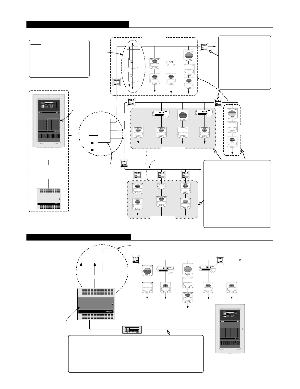
4100ES/4100U VNAC Wiring Reference
NOTE: Refer to NFPA 72, the
National Fire Alarm Code, for
requirements concerning fault
tolerance between Notification
Zones. Use of Isolator Modules
and/or fire rated risers may be
required depending on system
design.
TrueAlert SLC Source
Internally mounted
4100ES TrueAlert
Addressable Power
Supply (TPS)
Channel 1
Channel 2
4100ES (shown) or
4100U Fire Alarm
Control Panel
or RUI controlled
TrueAlert Addressable
Controller
TM
TrueAlert Addressable Controller
Channel 3
CAUTION
DISCONNECT
POWER
BEFORE
SERVICING
Wiring
reference
detail
Terminal cabinet
(as required)
Locate branch circuit
terminations within 10 ft
(3 m) of TrueAlert
Addressable SLC source
+ -
+ -
PORT 1
PORT 2
4905-9929 TRUEALERT ISOLATOR
INST. INSTR. 574-769 REV
576-733
RELAY CONTACTS
MODULE
3 AMP, 30 VDC
15 mA MAX 24 VDC
ADDRESS
ON
Simplex Time Recorder Co.
MSB
Gardner, MA 01441
Branch
1
Branch 3
Branch
2
+ -
+ -
PORT 1
PORT 2
4905-9929 TRUEALERT ISOLATOR
INST. INSTR. 574-769 REV
576-733
RELAY CONTACTS
MODULE
3 AMP, 30 VDC
15 mA MAX 24 VDC
ADDRESS
ON
Simplex Time Recorder Co.
MSB
Gardner, MA 01441
+ PORT 2
4905-9929 TRUEALERT ISOLATOR
INST. INSTR. 574-769 REV
RELAY CONTACTS
MODULE
3 AMP, 30 VDC
15 mA MAX 24 VDC
ON
Simplex Time Recorder Co.
Gardner, MA 01441
+ PORT 1
576-733
ADDRESS
MSB
+ PORT 2
4905-9929 TRUEALERT ISOLATOR
INST. INSTR. 574-769 REV
RELAY CONTACTS
MODULE
3 AMP, 30 VDC
15 mA MAX 24 VDC
ON
Simplex Time Recorder Co.
Gardner, MA 01441
VNAC Zone 1
+ PORT 1
576-733
ADDRESS
MSB
VNAC Zone 2
TrueAlert wiring
(twisted pair, 18 to 12 AWG)
+ -
+ -
PORT 1
PORT 2
4905-9929 TRUEALERT ISOLATOR
INST. INSTR. 574-769 REV
576-733
RELAY CONTACTS
MODULE
3 AMP, 30 VDC
15 mA MAX 24 VDC
ADDRESS
ON
Simplex Time Recorder Co.
MSB
Gardner, MA 01441
+ PORT 2
4905-9929 TRUEALERT ISOLATOR
INST. INSTR. 574-769 REV
RELAY CONTACTS
MODULE
3 AMP, 30 VDC
15 mA MAX 24 VDC
ON
Simplex Time Recorder Co.
Gardner, MA 01441
VNAC Zone 2
4905-9929 Isolator Modules:
+ -
+ -
PORT 1
PORT 2
4905-9929 TRUEALERT ISOLATOR
INST. INSTR. 574-769 REV
RELAY CONTACTS
MODULE
3 AMP, 30 VDC
15 mA MAX 24 VDC
ADDRESS
ON
Simplex Time Recorder Co.
Gardner, MA 01441
1. Locate as required, each
576-733
MSB
takes one address and counts
as 4
TrueAlert unit loads.
2. Isolator Modules are
automatically assigned to the
Isolator default VNAC.
3. Up to 12 total can be
connected per Class B SLC
(up to 6 on the same branch),
and up to 6 total per Class A
SLC.
+ -
+ -
PORT 1
PORT 2
4905-9929 TRUEALERT ISOLATOR
INST. INSTR. 574-769 REV
576-733
RELAY CONTACTS
MODULE
3 AMP, 30 VDC
15 mA MAX 24 VDC
ADDRESS
ON
Simplex Time Recorder Co.
MSB
Gardner, MA 01441
VNAC
Zone 1
VNAC Details:
1. VNACs can contain appliances across
+ PORT 1
576-733
ADDRESS
MSB
multiple SLCs and across multiple
TrueAlert control sources if controlled by
the same 4100ES/4100U panel.
2. Each appliance can be in up to 3
custom VNACs in addition to the default
VNACs.
3. Appliances are assigned to default
VNACs according to device type. Up to
255 VNACs (247 custom and 8 system
reserved) can be created per
4100ES/4100U panel with selectable
circuit and point types.
4. Up to 64 VNACs (56 custom and 8
system reserved) are available per
TrueAlert Addressable control source.
RUI Communications Wiring Reference
Locate branch circuit terminations within 10 ft
Terminal cabinet
(as required)
Channel 1
Channel 2
Channel 3
TrueAlert
Addressable
Controller
TM
TrueAlert Addressable Controller
CAUTION
DISCONNECT
POWER
BEFORE
SERVICING
Optional red
appliqué kit
4009-9805
RUI Communications Rules Summary:
1. Recommended limit of 20 TrueAlert Addressable Controllers. (4010ES has a
maximum internal and external limit of 20 card addresses.)
2. Can be wired with other RUI devices (LCD Annunciator shown for reference).
3. Wiring distance is up to 2500 ft (762 m) continuous wiring, and up to 10,000 ft
(3048 m) when "T" tapped (Class B only).
4. Minimum wiring is unshielded twisted pair (some applications may require
3 S4009-0003-10 9/2015
shielded twisted pair, consult your Simplex product supplier for details)
(3 m) of TrueAlert Addressable SLC source
+ -
+ -
PORT 1
PORT 2
4905-9929 TRUEALERT ISOLATOR
INST. INSTR. 574-769 REV
RELAY CONTACTS
MODULE
576-733
3 AMP, 30 VDC
15 mA MAX 24 VDC
ADDRESS
ON
Simplex Time Recorder Co.
MSB
Gardner, MA 01441
4603-9101 LCD
Annunciator
SYSTEM IS NORMAL
12:35:15 am MON 22 NOV 99
FIRE
ALARM
PRIORITY 2
SYSTEM
SYSTEM
POWER
DISPLAY
TIME
SILENCED
ALARM
ALARM
SUPERVISORY
TROUBLE
ON
ALARM
SUPV
TBL
ALARM
ALARM
SYSTEM
ACK
ACK
ACK
ACK
SILENCE
RESET
RUI Communications
+ -
+ -
PORT 1
PORT 2
4905-9929 TRUEALERT ISOLATOR
INST. INSTR. 574-769 REV
RELAY CONTACTS
MODULE
576-733
3 AMP, 30 VDC
15 mA MAX 24 VDC
ADDRESS
ON
Simplex Time Recorder Co.
MSB
Gardner, MA 01441
4100ES (shown) or 4100U,
4010ES, 4100, 4120, or 4020
Fire Alarm Control Panel

IDNet Communications Input
IDNet Addressable Communications Compatible.
For use with the Simplex 4010 Fire Alarm Control Panel,
up to five TrueAlert Addressable Controllers can be
controlled on a single IDNet communications channel
with each requiring only one point address. Each
TrueAlert Addressable Controller SLC channel can be
individually controlled by using 4010 custom control.
Each TrueAlert SLC channel can provide horn control
selected as Temporal pattern, March Time pattern (60 or
120 bpm), or Steady On.
Manual Control. Individual TrueAlert SLC channels
can be manually controlled from the 4010 for service
operations or for manual override.
Trouble Communications. The 4010 receives
TrueAlert Addressable Controller troubles to include:
device supervision (reported as a channel trouble), power
trouble, battery status, and earth detect.
Optional IDNet Repeater Modules. IDNet
communications can be repeated with the optional IDNet
Repeater Module or with the optional Fiber Optic
Receiver Module. Up to 100 of the IDNet channel points
can be repeated once (see illustrations below). Repeated
IDNet communications also support the “device level”
earth fault location utility of the host panel.
TrueAlert Addressable Controller with Wired IDNet Input Control
** SYSTEM IS NORMAL **
12:02:15pm Mon 9-Feb-98
SYSTEM
FIRE
SYSTEM
ALARM
AC
ALARM
SUPERVISORY
TROUBLE
SILENCED
PO W ER
SUPV
ALARM
ALARM
SYSTEM
TROUBLE
ACK
ACK
ACK
SILENCE
RESET
FIRE ALARM
CONT RO L
CAUTI O N
DISCO NNECT
PO WER BEF O RE
SERVICING
Typical IDNet compatible devices
(refer to individual devices for actual wiring
requirements, some wiring is not shown)
1
5
+ 24V
PULL DOWN
ALARMFIRE
ZONE PWR +
0V
2
6
ZONE PWR -
3
7
+IDNET
IDC +
4
8
- IDNET
IDC -
5
1
6
2
7
3
SIMPLEX TIME RECORDER CO.
4090-9101
MONITOR ZAM, CLASS B
INSTAL. INST R. 574-1 83
8
4
DATE CODE:
1
IDNet addressable communications channel,
shown Class B
Typical TrueAlert notification appliances
4010 Fire Alarm Control Panel
TrueAlert Addressable Controller
TM
TrueAlert Addressable Controller
CAUTION
DISCONNE CT
POWER
BEFORE
SERVICING
Three TrueAlert channels
with optional internal IDNet Repeater
1
5
+ 24V
ZONE PWR +
0V
2
6
ZONE PWR 3
7
+IDNET
IDC +
4
8
- IDNET
IDC -
5
1
6
2
SIMPLEX TIME RECORDER CO.
7
3
4090-9101
MONITOR ZAM, CLASS B
INSTAL. INST R. 574-1 83
8
4
DATE CODE:
1
Repeated
IDNet Channel:
PULL DOWN
ALARMFIRE
up to 100 devices maximum on repeater output,
250 devices total on IDNet Channel
IDNet devices and additional
TrueAlert Addressable Controller(s)
TrueAlert Addressable Controller with Fiber Optic IDNet Input Control
fiber cables, 3000 ft
Two
(914 m) maximum distance
** SYSTEM I S NORM AL **
12:02:15pm Mon 9-Feb-98
SYSTEM
FIRE
SYSTEM
ALARM
AC
ALARM
SUPERVISORY
TROUBLE
SILENCED
POW ER
SUPV
ALARM
TROUBLE
ALARM
SYSTEM
ACK
ACK
ACK
SILENCE
RESET
4010 Fire Alarm Control Panel
24 VDC power for
fiber optic transmitters
4090-9107, Class X (Style 7)
Output Fiber Optic Transmitter
4090-9105, Class B Output
Fiber Optic Transmitter
FIRE ALARM
CONT RO L
CAUTI O N
DISCO NNECT
POW ER BEFO RE
SERVICING
IDNet addressable communications channel;
Class B or Class A, Class B shown
Four
fiber cables, 3000 ft
(914 m) maximum distance
TM
4009 IDNet NAC EXTENDER
Repeated IDNet Channel: up to 100 devices maximum
on repeater output, 250 devices total on IDNet Channel
TM
4009 IDNet NAC EXTENDER
CAUTION
DISCONNECT
POWER
BEFORE
SERVICING
CAUTION
DISCONNECT
POWER
BEFORE
SERVICING
CAUTION
DISCONNECT
POWER
BEFORE
TM
4009 IDNet NAC EXTENDER
SERVICING
TrueAlert output channels (SLCs)
1
5
+ 24V
ZONE PWR +
ALARMFIRE
0V
2
6
ZONE PWR -
3
7
+IDNET
IDC +
4
8
- IDNET
IDC -
5
1
6
2
PULL DOWN
PULL DOWN
7
3
SIMPLEX TIME RECORDER CO.
4090-9101
MONITOR ZAM, CLASS B
INSTAL. INST R. 574-1 83
8
4
DATE CODE:
1
1
5
+ 24V
ZONE PWR +
ALARMFIRE
2
6
0V
ZONE PWR -
3
7
+IDNET
IDC +
4
8
- IDNET
IDC -
5
1
6
2
7
3
SIMPLEX TIME RECORDER CO.
4090-9101
MONITOR ZAM, CLASS B
INSTAL. INST R. 574-1 83
8
4
DATE CODE:
1
4009 IDNet NAC Extenders with optional
4 S4009-0003-10 9/2015
internal IDNet Fiber Receivers
TrueAlert output channels (SLCs)

Wired NAC Input Connection Information
Wired Conventional NAC Input Compatible. For
applications where existing (or new) conventional
Notification Appliance Circuits (NACs) are available, the
TrueAlert Addressable Controller can be controlled
directly from the NACs. (Refer to diagram below.)
Service Diagnostic Features
Power-up Self-Diagnostics. Upon power-up, the
TrueAlert Addressable Controller tests each module and
performs earth fault diagnostics. Trouble conditions are
communicated to the host control panel and are also
displayed on internal LEDs.
Flexible Connection Choices. Two NACs, from
either the same, or from different host fire alarm control
panels, can be connected to control the TrueAlert output
channels. Multiple control selections provide flexible
operation. (Refer to table below.)
NAC input to SLC output control is selectable per
the following table (configure NAC input as Steady On,
uncoded):
Input NAC
NAC 1
NAC 2
Output SLC Control Options
A B
Controls
visibles
Controls
audibles
Controls audibles and
visibles on Channel 1
Controls audibles and
visibles on Channels 2 and 3
Strobe Output. TrueAlert Addressable Strobes are
operated with synchronized flashes.
Horn Output. TrueAlert Addressable Horn operation is
selectable per TrueAlert Addressable Controller as either:
Temporal pattern, March Time pattern at either 60 or
120 bpm or Steady On.
Door Mounted Reference Label
A detailed programming and diagnostic label is located
inside the front door providing a quick reference for both
installation and checkout.
System troubles via RUI or IDNet communications
are reported with detailed information concerning which
TrueAlert Addressable Controller is involved and the
nature of the trouble. Messages include power and battery
status, earth fault, channel troubles, address problems, and
other information.
System Troubles via Wired Control. When
controlled with conventional NAC inputs, common
troubles are signaled by providing an open circuit that
disconnects the NAC wiring from its end-of-line resistor
but still allows a reversed polarity alarm to be received.
LED Status Indicators are provided for the following:
Five yellow status LEDs provide 22 separate
indications listed in priority of urgency. As a trouble is
eliminated, any remaining trouble(s) will then be
indicated until the TrueAlert Addressable Controller is
returned to normal operation
Three separate yellow LEDs indicate which of
the three TrueAlert channels are involved for channel
specific troubles
AC power status is indicated by a green LED that
is on when AC is normal. During low AC (brownout)
conditions or with no AC, the LED is off. Additional
power and battery status is indicated by the general
status LEDs
TrueAlert Addressable Controller with Wired Control
NAC 1 control for visible
notification (on-until-silenced)
or control both audibles and
visibles on Channel 1
NAC 2 Control for audible
notification (on-until-reset) or
control both audibles and
visibles on Channels 2 and 3
**SYSTEM IS NORMAL**
12:02:15pm Fri 19-Feb-99
FIRE
SYSTEM
SYSTEM
ALARM
ALARM
SUPERVISORY
TROUBLE
SILENCEDACPOWER
ALARM
SUPV
TROUBLE
ALARM
ACK
ACK
ACK
SILENCE
Fire Alarm Control Panel
with Conventional NACs
SYSTEM
RESET
Additional
NAC Control
NAC
inputs
TM
TrueAlert Addressable Controller
TrueAlert Addressable
Controller
NOTE: Select NAC control for Steady On
(uncoded) operation
TrueAlert Addressable Controllers
controlled by two NAC inputs
TM
TrueAlert Addressable Controller
CAUTION
DISCONNECT
POWER
BEFORE
SERVICING
Three TrueAlert channels
Up to four TrueAlert
Addressable Controllers
CAUTION
CAUTION
DISCONNECT
POWER
BEFORE
SERVICING
TM
TrueAlert Addressable Controller
DISCONNECT
POWER
BEFORE
SERVICING
can be connected to
one conventional NAC
5 S4009-0003-10 9/2015

4090-9105/9107 IDNet Fiber Optic Transmitter Mounting Information
Surface mount box:
Simplex model 2975-9217
(ordered separately)
use 6-gang box, RACO # 960, 2-1/2" deep
(64 mm), or RACO # 965, 3-1/2" (89 mm)
Flush mount ganged boxes:
use 6-gang box, 1-1/2" (38 mm)
minimum depth; six, RACO # 400
or equal, (supplied by others)
Flush mount masonry box:
deep, or equal (supplied by others)
IDNet fiber optic transmitter:
4090-9107, Shown, Class X (Style 7) output
4090-9105, Not shown, Class B (Style 4) output
INSTALLATION NOTE:
Fiber optic cable bend radius should be 2" (51 mm)
minimum, or per Manufacturer's specification.
Six gang blank cover plate (Mulberry Metal
Products 97156 or equal), by others
TrueAlert Addressable Controller Mounting and Module Placement Reference
16-1/4" (413 mm)
10-29/32" (277 mm)
Optional Class A
adapter module
System Module
IDNet repeater or
Fiber optic receiver
12" (305 mm)
Battery location, no conduit entry or wiring in
this area (12.7 Ah battery outline shown)
Door, 5/8"
(16 mm) thick
Exposed cabinet
dimension for
semi-flush mount
1" (25.4 mm),
1-3/8" (35 mm) with
semi-flush trim
Cabinet depth
4-1/8" (105 mm)
13-1/2"
(343 mm)
Knockouts for screw
or nail mounting holes
Non-power limited wiring area (AC input)
Wall surface reference for semi-flush mount
Optional Semi-Flush Trim Kit
1-3/16" wide (30 mm),
3/8" (9.5 mm) thick
NOTE: Recommended conduit entrance varies with module selection. For models 4009-9401 and 4009-9402CA, refer to
Installation Instructions 574-762, specific option module installation instructions, and to Field Wiring Diagram 842-158
before locating conduit entrance. [NOTE: For model 4009-9501, refer to Installation Instructions 579-321 and Field
Wiring Diagram 842-244.]
6 S4009-0003-10 9/2015

TrueAlert Addressable Controller and 4100ES TPS Reference Specifications
NOTE: Refer to data sheet S4100-0065 for additional 4100ES TrueAlert Addressable Power Supply (TPS) specification details.
Input
Voltage
Wired Control Input, requirements per circuit
120 VAC Input (4009-9401/9402CA) 3 A @ 102-132 VAC, 60 Hz
240 VAC Input (4009-9501) 1.5 A, selectable for 220/240 VAC, +10% - 15% per selection, 50/60 Hz
3 mA @ 24 VDC; input voltage range = 16 to 33 VDC, filtered; control from conventional
reverse polarity NAC
Output Ratings
TrueAlert Channel Output Voltage (SLC) 19 to 31 VRMS, Special Application control
Compatible Special Application Appliances
Category Details TrueAlert ES Appliance Control Limitation
Available Strobe Intensity 15, 30, 75, and 110 cd
Appliance Control
Characteristics
SLC Ratings
and Loading
Auxiliary Output 500 mA @ 24 VDC nominal (requires 734-035 wiring harness)
TrueAlert SLC Wiring UTP, unshielded twisted pair, 18 to 12 AWG
TrueAlert Strobe Wiring Distance Maximum wiring distance between TrueAlert strobes is limited to 30 Ω wire resistance
Wiring Connections Terminal blocks for 18 to 12 AWG
Available Horn Control
Appliance Voltage
Minimum
TrueAlert Addressable
Controller or 4100ES TPS
TrueAlert Addressable
Controllers
4100ES TPS Up to 46 multi-candela strobes can be synchronized per SLC; total current per TPS = 9 A
Simplex TrueAlert and TrueAlert ES addressable notification appliances (with limitations);
contact your Simplex product representative for compatible appliances
Not compatible with TrueAlert ES intensities of
135 and 185 cd
Continuous, Temporal Code 3,
and March Time of 60 or 120 bpm
17 VRMS
Up to 63 total addressable appliances
Up to 75 unit loads (appliances are 1 unit load)
Up to 32 fixed candela (legacy) strobes can be synchronized per SLC
Up to 39 multi-candela strobes can be synchronized per SLC;
total current per controller = 8 A
Not compatible with TrueAlert ES horn tones of
Temporal Code 4 or 20 bpm
Not compatible with TrueAlert ES 23 VRMS appliance
voltage minimum
Optional Modules
Input Power 70 mA @ 24 VDC, system supplied
IDNet Repeater
Module
(4009-9809)
Fiber Optic
Receiver
Modules
General
IDNet Input, One Address Maximum distance from IDNet source is 2500 ft (762 m)
IDNet Output
Specifications
4009-9810 Class B, 65 mA @ 24 VDC, system supplied
Input Current
IDNet Output Specifications Same as those for Repeater Module (see above)
Fiber Optic Transmission Distance = 3000 ft (914 m) maximum
Operating Temperature 32° to 120° F (0° to 49° C)
Operating Humidity Range 10% to 90% RH from 32° to 104° F (0° to 40° C)
4009-9811
Repeated IDNet output for up to 100 devices (total IDNet devices not to exceed 250 per
channel)
Refer to specific panels details for additional IDNet communications specifications
Class X (Style 7), 80 mA @ 24 VDC, system supplied
(NOTE: Fiber optic input is Class X, repeated IDNet output is Class A)
Fiber Optic Transmitter Specifications
Input Voltage 18.9-32 VDC from compatible listed fire alarm supply
Input Current
Fiber Optic Connections
and Cable Requirements
(Type ST Connectors)
Module Size (with mounting bracket) 6-13/16” W x 3-3/4” H x 1-1/8” D (173 mm x 95 mm x 29 mm)
On-board Status Indicators
Communications Simplex IDNet format
Fiber Optic Transmission Distance 3000 ft (914 m) maximum
Wiring Connections Terminal blocks for 18 to 12 AWG
Operating Humidity Up to 90% RH, non-condensing @ 100° F (38° C)
Operating Temperature 32° to 120° F (0° to 49° C)
7 S4009-0003-10 9/2015
4090-9105 Class B, 30 mA @ 24 VDC
4090-9107 Class X (Style 7), 35 mA @ 24 VDC
4090-9105 Class B input, two fiber cables required
4090-9107 Class X (Style 7) input, four fiber cables required
Green LED Flashing = transmit
Red LED Flashing = receive
4090-9107 Separate Red LED = Class X (Style 7) receive

TrueAlert Addressable Controller Current Reference
Panel Module Selection (shaded model numbers are optional modules)
Model Description
4009-9401
4009-9402CA
4009-9501
4009-9812
4009-9809*
4009-9810*†
4009-9811*†
120 VAC input
240 VAC input
Class A Adapter 7 mA + 7 mA +
IDNet Repeater 70 mA
Fiber Optic Receiver, Class B 65 mA 65 mA
Fiber Optic Receiver, Class X 80 mA 80 mA
Supervisory
Current
Basic Panel 88 mA 88 mA 195 mA 195 mA
Actual
Supervisory
+
Alarm Current Actual Alarm
70 mA
+
IDNet Devices, 0.7 mA each, maximum of 100
(see Procedure Note 5)
TrueAlert Appliances/Devices, Supervisory
Current, 0.2 mA per unit load, add devices from
all 3 SLCs (see Procedure Note 7)
TrueAlert Isolators; each requires 1 address
and four (4) unit loads
Auxiliary Power Output, calculate per total
device requirements (see Procedure Note 5)
Total Supervisory Current =
total devices
x 0.7 mA each
total loads
x 0.2 mA each
total Isolators
x 10 mA
500 mA
maximum
+
total devices
x 0.7 mA each
+
+
+
(A)
total Isolators x
maximum
10 mA
500 mA
Total TrueAlert Addressable Controller Panel Alarm Current =
* Only one of these three modules can be chosen for a single TrueAlert Addressable Controller.
† NOTE: IDNet Fiber Optic Transmitter current is supplied from the host fire alarm control panel.
TrueAlert Channel Notification Appliance Current Loads
TrueAlert Channel (SLC) 2.5 A maximum per channel (see Procedure Note 5)
Total TrueAlert Channel Loads Alarm Current =
Total TrueAlert Addressable Controller Panel Alarm Current (enter B1 from above) =
Channel Number NAC Alarm Current
Channel 1
Channel 2 +
Channel 3 +
(A1)
+
+
(A2)
+
(B1)
(C)
(B2) +
Total Alarm Current =
(D)
Procedure:
1. Calculate total panel supervisory current (A).
2. Calculate total panel alarm current (B1) [convert mA to A, example: 350 mA = 0.35 A]. Copy (B1) into block (B2).
3. Calculate total NAC loads alarm current from notification appliance ratings (C).
4. Add (C) + (B2) to determine total alarm current (D).
5. Total of IDNet Device Current (A1) + Auxiliary Power Output Current (A2) + SLC Loads Alarm Current (C) is 8 A
maximum.
6. Refer to Simplex battery selection document 900-012 for recommended battery size for specific standby requirements
(i.e., 24 hours supervisory, 5 minutes of alarm). Internal cabinet space is provided for batteries up to 12.7 Ah.
7. Most TrueAlert appliances/devices are one unit load, Isolators are 4 unit loads. Refer to Field Wiring Diagram 842-158.
TYCO, SIMPLEX, and the product names listed in this material are marks and/or registered marks. Unauthorized use is strictly prohibited. NFPA 72 and National Fire Alarm and
Signaling Code are registered trademarks of the National Fire Protection Association (NFPA).
Tyco Fire Protection Products • Westminster, MA • 01441-0001 • USA S4009-0003-10 9/2015
www.simplex-fire.com
© 2015 Tyco Fire Protection Products. All rights reserved. All specifications and other information shown were current as of document revision date and are subject to change without notice.
 Loading...