

Simplex STS DAY TANK User Manual
STS DAY TANK
PACKAGED DAY TANK SYSTEMS

Last Revision Date: September 20, 2018
For the most up-to-date information for this product and others, please
contact Simplex, Inc. at (800) 637-8603 or visit us on the web at
http://www.simplexdirect.com.

Table of Contents
1 Warnings and Cautions ........................................ 1
Safety information symbols 1
Cautions 1
2 Nameplates and Placards ..................................... 3
3 Installation ...................................................... 5
Overview of use 5
Installation Operations 6
Vent Openings 9
Day Tank Pump Priming Procedure 10
4 Day Tank Operation ........................................... 11
Automatic Operation 12
High Level Fill Disabled 14
Fill Test Pushbutton 14
Low Level Alarm 15
Manual Operations 15
Lamp Test 15
Automatic Duplex Pump Controller, Option 345 16
Overflow-Return Tank, Option 383 17
Overflow-Return Pump/Controller Added to Day Tank, Option 390 18
5 Maintenance .................................................... 19
Each Year 19
After the First Three Years 19
6 Troubleshooting .............................................. 20
No Fuel Delivered 20
Insufficient Fuel Delivered 20
Rapid Pump Wear 20
Pump Delivers for Short Period and Quits 20
Pump Requires too Much Power 20
Noisy Operation 20
Pump Requires Frequent Re-Priming 21
Motor Does Not Turn or Turns Intermittently 21
Pump Leaks Fuel 21
7 Drawings and Parts List ..................................... 22
Abbreviation Index 22
Technical Data 23
Appendix A Product Warranty ................................. 25

1 WARNINGS AND CAUTIONS
1
Safety
information
SymbolS
CautionS
The following images indicate important safety information:
This General warning symbol points out important
information that, if not followed, could endanger
personal safety and/or property.
This Explosion warning symbol points out potential explosion hazards.
This Fire warning symbol points out potential fire
hazards.
This Electrical warning symbol points out potential
electrical shock hazards.
• Improper operation of this equipment such as neglecting its
maintenance or being careless can cause possible injury or
death. Permit only responsible and capable persons to install,
operate, and/or maintain this equipment.
• Potentially lethal voltages and amperages are present in these
machines. Ensure all steps are taken to render the machine
safe before attempting to work on the equipment.
• All hardware covered by this manual have dangerous electrical voltages and can cause fatal electrical shock. Avoid
contact with bare wires, terminals, connections, etc., on the
hardware, if applicable. Ensure all appropriate covers, guards,
grounds, and barriers are in place before operating the equipment. If work must be done around an operating unit, stand
on an insulated dry surface to reduce shock hazard.
• Do not handle any kind of electrical device while standing in
water, while barefoot, or while hands or feet are wet. DANGEROUS ELECTRICAL SHOCK MAY RESULT.
• If trained personnel must stand on metal or concrete while
installing, servicing, adjusting, or repairing this equipment,
place insulative mats over a dry wooden platform. Work on
the equipment only while standing on such insulative mats.
• The National Electrical Code (NEC), Article 250 requires the
frame of the equipment to be connected to an approved earth
ground and/or grounding rods. This grounding will help
prevent dangerous electrical shock that might be caused by a
ground fault condition or by static electricity. Never disconnect the ground wire.
• Wire gauge sizes of electrical wiring, cables, and cord sets
must be adequate to handle the maximum electrical current
(ampacity) to which they will be subjected.
2
• Before installing or servicing this (and related) equipment,
make sure that all power voltage supplies are completely
turned off at their source. Failure to do so will result in hazardous and possibly fatal electrical shock.
• In case of accident caused by electric shock, immediately shut
down the source of electrical power. If this is not possible,
attempt to free the victim from the live conductor. AVOID
DIRECT CONTACT WITH THE VICTIM. Use a nonconducting implement, such as a dry rope or board, to free the
victim from the live conductor. If the victim is unconscious,
apply first aid and seek immediate medical attention.
• Never wear jewelry when working on this equipment. Jewelry can conduct electricity resulting in electric shock or may
get caught in moving components causing injury.
• Keep a fire extinguisher near the hardware at all times. Do
NOT use any carbon tetra-chloride type extinguisher. Its
fumes are toxic, and the liquid can deteriorate wiring insulation. Keep the extinguisher properly charged and be familiar
with its use. If there are any questions pertaining to fire extinguishers, please consult the local fire department.
• The illustrations in this manual are examples only and may
differ from your unit.

3
2 NAMEPLATES AND PLACARDS
Nameplates and Placards — 3

4 — Nameplates and Placards
4

If you have any questions regarding Day Tank
installation, call Simplex service at (800) 637-8603
(24 hrs.).
5
3 INSTALLATION
O
verview of
Location of the Day Tank is of prime importance and
should be done by trained personnel. It is one of the
Use
most critical factors involved in reliable and safe
operation. The Day Tank must be positioned and
installed according to the main fuel storage tank and
engine location. In general, locate the Day Tank as close
to the engine as possible consistent with applicable local
and national plumbing and electrical codes. Always
position the Day Tank so that the highest fuel level in the
tank is lower than the engine injectors. The Day Tank
must be located not farther than 200' from the main fuel
tank. The Day Tank must not be more than 18' higher
than the lowest fuel level in the main fuel tank. Never
locate the Day Tank in a confined space without
consideration for accidental fuel spillage and use a
rupture basin when necessary. Never locate the Day
Tank near a surface or object which may be adversely
affected by fuel oil. Never locate a Day Tank system
above a residential living space.
See dimensional drawing for port sizes. All plumbing to
and from the Day Tank should be black iron pipe or copper
tubing. All plumbing connections at the tank should be
made with pipe unions to facilitate installation and service.
Special attention must be given to pump suction pipe
connections to avoid possible air leaks and subsequent loss
of pump prime. Never allow the Day Tank pump to run
“dry” as immediate pump damage will occur. Before
applying power to the pump/motor be sure all fuel
connections have been made and tightened and all holes are
plugged. Option 010 or 015, auxiliary hand pump, is
recommended for installation on all Day Tanks with motorpumps. The hand pump is used for initial priming of the
fuel line from the main tank and as a back up to the motor
pump.
I
6
nstallation
Operations
1. Remove the Day Tank top. Check all visible hardware for
tightness. Attach the Vent Pipe. This is an NPT internal
connection. The vent pipe allows equalization of internal
Day Tank pressure.
THE VENT LINE!
DO NOT INSTALL A VALVE IN
Venting provides pressure relief in case
of overfill, rapid expansion, or gasification of contents in
the event of fire. The Day Tank may become
permanently distorted at pressures above 5PSI (10 and 25
gallon) and 3PSI (50–400 gallon) and may rupture at
pressures above the maximum withstand pressure of 25PSI
(10 and 25 gallon) and 15PSI (50–400 gallon). Day Tank
operation without a vent pipe is strictly not recommended.
The vent pipe should be at least 5 feet higher than any
other pipe and should terminate outdoors. The vent pipe
must be installed per local building codes and per NFPA
30 including but not limited to Section 19.5.3. There should
be no low portions or sags in the vent pipe which can trap
liquid. The end of the pipe should be fitted with a 180°
weather protected vent cap to shed water and should be
screened to keep out pests, leaves, etc.
2. Attach the Overflow Pipe. This is an NPT internal
connection. Simplex recommends the configuration shown
in the illustration below. The overflow pipe runs from the
Day Tank back to the main storage tank and allows for
draining of the tank should it become overfilled. This pipe
should be sized at least twice the diameter of the pump fill
pipe (minimum 1"I.D. for 10 and 25 gallons; minimum 2"
I.D. for 50-500 gallon). If the tank becomes overfilled and
the overflow line is not connected or is obstructed the tank
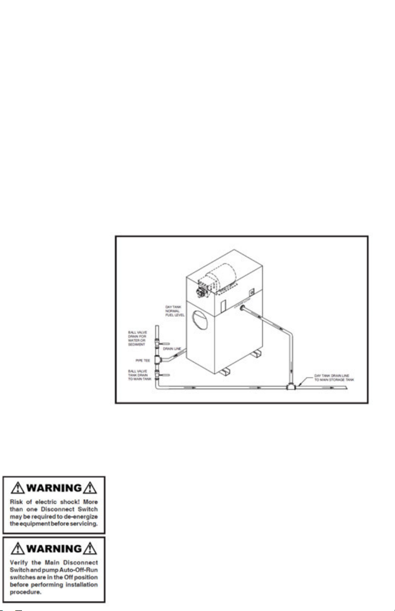
I
7
nstallation
Operations
Contd
.
will distort and possibly rupture. In installations where the
main fuel tank is above ground the overflow pipe should
be connected to an Overflow Tank (Option #390
Recommended).
OVERFLOW LINE!
DO NOT INSTALL A VALVE IN THE
3. Attach the Day Tank Intake Line (fill pipe) from the main
fuel tank to the pump inlet. This is an NPT internal
connection. Use black pipe with a union and size per the
installation drawing in this manual. Optional fuel strainer
(Option 060) with #60 mesh is recommended.
4. Attach the Engine Supply Line. This is an NPT external
connection. Use black pipe with a union and size per the
dimensional drawing in this manual. Attach the Engine
Return Line. This is an NPT internal connection. Use black
pipe with a union and size per the installation drawing in
this manual.
5. Attach the Engine Return Line. This is a NPT internal
connection. Use black pipe with a union and size per the
installation drawing in this manual.
6.
WARNING! Verify the Day Tank mode selector switch is
in the “Off” position.
Supply a 115-1-60, 15A, circuit
breaker protected circuit from a reliable power bus to the
control power terminal board (TB”PS”) at terminals 1 and
2.
GROUND THE DAY TANK!
Secure the conduit end to
the left side of the cover at the holes provided. Replace the
cover.
7.
The pump has been pre-lubricated with heavy oil prior to
shipment. Prime the system by using the hand pump
(Option 010 or 015) to transfer fuel from the main tank to
 Loading...