

Page 1

SATURN
1400KW3200KW
STATIONARY LOAD BANK
Page 2

Last Revision Date: March 15, 2016
For the most up-to-date information for this product and others, please
contact Simplex, Inc. at (800) 637-8603 or visit us on the web at
http://www.simplexdirect.com.
Page 3

Table of Contents
1 Warnings and Cautions ........................................................1
Safety information symbols 1
Cautions 1
2 Description and Specication .............................................. 4
Overview of Use 4
Control System 4
Cooling System 4
Load System 4
Safety 4
3 Unpacking ............................................................................. 6
Included Components 6
Primary Inspection 6
4 Installation ............................................................................ 7
Load Bank Placement 7
Installation Procedure 8
Remote HMI installation 9
Load Dump installation 10
Current Transformer installation 11
MODBUS installation 13
Heater installation 14
BMS/BAS Installation 15
5 Setup .................................................................................... 16
General Settings 16
Automatic Mode 16
6 Operating Instructions ....................................................... 17
Pre-operation checks 17
Setting up the test 17
Testing operation 18
Metering (if equipped) 18
Shutdown and cooling 18
7 Automatic Mode ................................................................. 19
Overview 19
Setting Up Automatic Mode 20
Entering Automatic Mode 20
Page 4

8 Maintenance/Troubleshooting .......................................... 21
General maintenance 21
Each Operation 21
Every 6 Months 21
Troubleshooting 22
9 Alarms and Warnings .......................................................... 23
Alarms 23
Warnings 23
APPENDIX A PARTS LISTINGS ...........................................................25
APPENDIX B MODBUS CONTROLS ...................................................41
Modbus Control Directions 44
APPENDIX C PRODUCT WARRANTY .................................................45
Page 5

Table of Figures
Current draw at specic resolutions (in kilowatts) ...............................5
Air Flow ................................................................................................................7
Ground Bus ......................................................................................................... 8
Main Load Bus ...................................................................................................8
Conduit Opening .............................................................................................. 8
HMI TBH................................................................................................................9
Serial Adapter ....................................................................................................9
TB-DC .................................................................................................................... 9
Load Dump Jumper ...................................................................................... 10
Current Transformers ................................................................................... 11
CT Orientation ................................................................................................ 11
TB-CT .................................................................................................................. 11
Current Transformer placement for Metering ..................................... 12
Current Transformer placement for Auto/Regen. Mode ................. 12
TB-COM ............................................................................................................. 13
Modbus Serial Converter ............................................................................ 13
TB-SH .................................................................................................................. 14
TBR ...................................................................................................................... 15
Setup Screen ................................................................................................... 16
General Settings............................................................................................. 16
HMI Information ............................................................................................. 18
Alarm History .................................................................................................. 18
Automatic/Regenerative Mode ................................................................ 19
Setup Screen ................................................................................................... 19
Automatic Mode Setup ............................................................................... 19
Automatic Mode Running .......................................................................... 20
Troubleshooting ............................................................................................ 22
Troubleshooting alarms .............................................................................. 24
Right Subpanel Layout ................................................................................ 25
Option D - Automation/Metering............................................................ 26
Page 6

Option B - Communication (TCP/IP Data Logging) ........................... 27
PLC Component list ...................................................................................... 28
Control Relays ................................................................................................. 30
Terminal Blocks ............................................................................................... 32
Option 010 - Space Heaters ....................................................................... 34
Center Subpanel ............................................................................................ 36
Phase A Detail ................................................................................................. 37
Phase B Detail ................................................................................................. 38
Phase C Detail ................................................................................................. 39
Load Control Terminal Blocks ................................................................... 40
Modbus Controls (Read/Write) ................................................................. 41
Modbus Indications (Read only) .............................................................. 42
Page 7

1 WARNINGS AND CAUTIONS
Safety
information
SymbolS
CautionS
e following images indicate important safety information:
is General warning symbol points out important
information that, if not followed, could endanger
personal safety and/or property.
is Explosion warning symbol points out
potential explosion hazards.
is Fire warning symbol points out potential re
hazards.
is Electrical warning symbol points out potential
electrical shock hazards.
is load bank is high-powered, technical, industrial
equipment operating at dangerous voltages and temperatures. It
is capable of damaging itself, property or personnel if improperly
used. It is not a consumer product.
It must be installed, connected and operated by personnel
properly trained and experienced in its use. An operator’s
manual is supplied with each load bank and available online at
www.simplexdirect.com. e operator must be familiar with its
contents and have access to it during operation.
• High Voltage: Turn o and disconnect power source before
opening this equipment
• High Temperature: Allow hardware to cool before servicing
or opening this equipment.
• Rotating Equipment: Ensure that the fans have stopped
before opening this unit.
• For Operator Safety: Make sure this equipment is properly
grounded when in use.
All compression-type connections on fuse blocks, load blocks,
and contactors should be checked for tightness frequently. is
check should be established as part of routine maintenance.
e following cautions should be observed before and during
operation:
• Check intake and exhaust screens as well as fan and load
elements for foreign objects.
• Position and install the load bank with consideration given
Warnings and Cauons — 1
Page 8

to large cubic airow requirements, exhaust temperature, and
velocity. Do not point exhaust at any nearby surface or object
that may be adversely aected by high temperature. is
includes but is not limited to painted surfaces, tar paper and
asphalt roofs, water sprinkler heads, re alarms, and volatile
material.
• Do not use in conned spaces. Do not allow the load bank’s
feet to sink into so surfaces thereby cutting o bottom air
intake. e load bank may have to compete with cooling air
requirements of a nearby running engine generator set where
cooling air intake to a conned space may not be adequate
for both engine and load bank. Be especially careful not
to bounce hot exhaust air o nearby obstructions for recirculation through the load bank.
• Verify that all control switch positions are set correctly for
your intended usage before connecting the load bank to the
source to be tested.
• e load cables carry high amperage. Be constantly aware of
possibility of inductively heating adjacent ferrous objects to
temperatures sucient to damage cable insulation.
• Always connect the safety ground cable to a proper ground.
Do not rely on a possible grounded neutral somewhere else
in the system.
• Do not let the load bank run unattended for long periods of
time.
• Do not store or operate in rain unless adequate protection is
provided.
• Routinely inspect all components and electrical connections
for tightness and integrity.
• Repair any damaged or degraded components and wiring
without delay.
• If technical assistance, service, or parts are needed, please call
800-837-8603 (24 Hours).
• All hardware covered by this manual have dangerous
electrical voltages and can cause fatal electrical shock. Avoid
contact with bare wires, terminals, connections, etc. Ensure
all appropriate covers, guards, grounds, and barriers are in
place before operating the equipment. If work must be done
around an operating unit, stand on an insulated dry surface
to reduce the risk of electrocution.
• Do not handle any kind of electrical device while standing
in water, while barefoot, or while your hands or feet are wet.
• If people must stand on metal or concrete while installing,
servicing, adjusting, or repairing this equipment, place
insulative mats over a dry wooden platform. Work on the
2 — Warnings and Cauons
Page 9

equipment only while standing on such insulative mats.
• e National Electrical Code (NEC), Article 250 requires
the frame to be connected to an approved earth ground
and/or grounding rods. is grounding will help prevent
dangerous electrical shock that might be caused by a ground
fault condition or by static electricity. Never disconnect the
ground wire while the load bank is in use.
• Wire gauge sizes of electrical wiring, cables, and cord sets
must be adequate to handle the maximum electrical current
(ampacity) to which they will be subjected.
• Before installing or servicing this (and related) equipment,
ensure that all power voltage supplies are completely turned
o at their source. Failure to do so can result in hazardous
and possibly fatal electrical shock.
• In case of accident caused by electric shock, immediately
shut down the source of electrical power. If this is not
possible, attempt to free the victim from the live conductor.
AVOID DIRECT CONTACT WITH THE VICTIM. Use
a nonconducting implement, such as a dry rope or board,
to free the victim from the live conductor. If the victim is
unconscious, apply rst aid and seek immediate medical
attention.
• Never wear jewelry when working on this equipment. Jewelry
can conduct electricity resulting in electric shock or may get
caught in moving components causing injury.
• Keep a re extinguisher near the hardware at all times.
Do NOT use any carbon tetra-chloride type extinguisher.
Its fumes are toxic, and the liquid can deteriorate wiring
insulation. Keep the extinguisher properly charged and be
familiar with its use. If there are any questions pertaining to
re extinguishers, please consult the local re department.
• e illustrations in this manual are examples only and may
dier from your load bank.
• Load Bank warranty is void if incorrectly cooled.
Warnings and Cauons — 3
Page 10

2 DESCRIPTION AND SPECIFICATION
overview of
u
Se
Control
S
yStem
Cooling
S
yStem
Simplex Saturn load banks are precision test instruments
designed to apply a selectable load to a power source and measure
the source’s response. ey are used for routine maintenance
exercise to ensure the long-term reliability and readiness of the
standby generator. Load banks can also eliminate the detrimental
eects of unloaded operation of diesel engine generators as well
as prevent damage from reverse power generation.
Saturn load banks are available in models ranging from 1400
kilowatts up to 3200 kilowatts. All standard Saturn models have
a step resolution of 25 kilowatts.
Saturn load banks feature a Human-Machine Interface
(HMI) touchscreen, which controls load bank operation and
displays the unit’s status. With the HMI, the operator can apply
a desired load and measure the response of the test source.
e load bank can also be integrated into your facility’s BMS/
BAS system via standard Modbus RS-485 or optional Modbus
TCP/IP, as well as a set of dry contacts for status reporting.
Saturn load banks are cooled by forced air, delivered by an
aluminum fan blade directly driven by a TEFC motor. e air is
brought in on the bottom of the load bank and expelled through the
top. Optional equipment allows the exhaust to be driven through a
customer-installed duct, providing for indoor installation.
load SyStem
Safety
4 — Descripon and Specicaon
e load system comprises independently controlled Simplex
Powr-Web resistors, which have been designed specically for
use in load bank systems. e load elements are supported by
high-temperature, ceramic-clad, stainless-steel rods across their
entire length, virtually eliminating element-to-element short
circuits. e elements are arrayed in discrete trays, which are
independently serviceable.
e Saturn is protected by sensors to ensure that the load
bank is suciently cooled and that the exhaust does not exceed a
safe temperature, which could damage the load bank or present
a safety hazard to the operator. When a failure occurs, the safety
system immediately removes the load to protect the equipment
from permanent damage.
Page 11

1400 1500 1600 1700
416V
480V
600V
416V
480V
600V
416V
480V
600V
416V
1943A 2082A 2221A 2359A
1684A 1804A 1925A 2045A
1347A 1443A 1540A 1636A
1800 1900 2000 2100 2200
2498A 2637A 2776A 2915A 3053A
2165A 2285A 2406A 2526A 2646A
1732A 1828A 1925A 2021A 2117A
2300 2400 2500 2600 2700
3192A 3331A 3470A 3608A 3747A
2766A 2887A 3007A 3127A 3248A
2213A 2309A 2406A 2502A 2598A
2800 2900 3000 3100 3200
N/A N/A N/A N/A N/A
480V
600V
ese measurements are based on ideal numbers. ey do not take into account
control power draw, power cable resistance, voltage droop, etc.
3368A 3488A 3608A 3729A 3849A
2694A 2791A 2887A 2983A 3079A
Descripon and Specicaon — 5
Page 12

3 UNPACKING
.
inCluded
C
omponentS
primary
i
nSpeCtion
If any
problems
are observed
during
Primary
Inspection,
call Simplex
24 hours a
day at
800-637-8603
e following items are included with your load bank. If any
of the following are not included, please contact Simplex Direct
at 800-637-8603.
1. Load bank
2. Controller (remote or local)
3. Manual
4. Drawing package
Optional equipment
1. Additional controllers
2. Exhaust hood
3. Current transformers
4. Other optional equipment
Before installing your Saturn, inspect the shipping crate and
load bank. Physical or electrical problems could arise from
handling and vibration. Never apply power to a load bank before
performing this procedure. e following ve-point inspection
is recommended before installation and as part of a 6-month
maintenance schedule or when the load bank is relocated:
1. If the crate shows any signs of damage, examine the load
bank in the corresponding areas for signs of initial problems.
2. Check the entire outside of the cabinet for any visual damage,
which could cause internal electrical or mechanical problems
due to reduced clearance.
3. Open the control panel door and inspect all relays and
control modules. Make sure all components are secure in
their bases and safety bails are in place. Spot-check electrical
connections for tightness. If any loose connections are found,
inspect and tighten all remaining connections.
4. Examine all accessible internal electrical components such
as fuses, contactors, and relays. Check lugged wires at these
components.
5. Check the load element chamber for foreign objects, broken
ceramic insulators, and mechanical damage.
6 — Unpacking
Page 13
4 INSTALLATION
load bank
p
laCement
Improperly
installing
this unit may
result in
damage or
destruction
of the
load bank,
adjacent
equipment,
and the
building
housing the
unit.
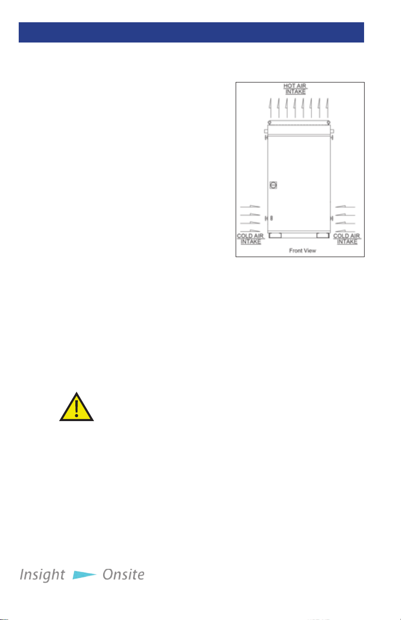
Normally equipped,
Saturn load banks are
intended for outdoor
installation. A forced air
system, which discharges
out of the top of the unit,
cools the load elements
(See Figure 1 Air Flow.)
Load banks require large
quantities of air circulation,
so it is essential to install the
unit in an area that provides
adequate airow. Before
conducting load tests, a
review of site conditions
by trained personnel is
recommended.
e load bank requires at least 20 feet of vertical clearance; 6
feet of clearance on the front, le, and right; and 1.5 feet of
clearance in the rear (see “Figure 2 Clearance requirements”
on page 11).
e load bank should be placed in a secure area accessible by
trained personnel only.
Figure 1 Air Flow
Because the unit generates a lot of heat, never operate near
sprinkler systems.
Operating the load bank in a conned space will recycle hot
exhaust air through the cooling system, which can cause severe
damage.
e load bank may compete with nearby generators for
cooling air.
Installaon — 7
Page 14
inStallation
p
roCedure
Saturn load
banks feature
a power
outlet in the
control panel
for your use.
This outlet is
limited to 2
amps.
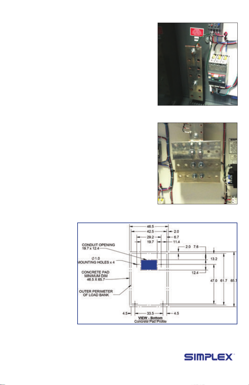
1. To bring in the source’s
power cables, pull holes
in the Conduit Opening,
located in the bottom of
the load bank’s control
panel enclosure (see
Figure 5 Conduit
Opening).
2. Conrm the test source is
properly grounded.
3. Ground the load bank
by connecting the
Grounding Bus to an earth
ground or grounding rod.
See Figure 3 Ground Bus
4. Connect the source’s
power output to the load
bank via the Main Load
Bus with appropriately
sized cables (see Figure 4
Main Load Bus).
Figure 2 Ground Bus
Figure 3 Main Load Bus
8 — Installaon
Figure 4 Conduit Opening
Page 15
remote Hmi
inStallation
If your HMI is installed
directly on the load bank,
skip to the next section.
1. Mount the HMI where
desired.
2. Connect the HMI to the
Load Bank by swinging
the HMI’s screen out to
expose the TB-H terminal
block (see Figure 6 HMI
TBH) and wiring it to the
Load Bank.
A. Using a Belden 9841
or equivalent cable,
make the following
connections between
the HMI’s TB-H
terminals to the Serial
Adapter (see Figure 7
Serial Adapter).
1. TB-H 4 → TXD+
2. TB-H 5 → TXD-
3. Wire shielding →
COM B
Figure 5 HMI TBH
Figure 6 Serial Adapter
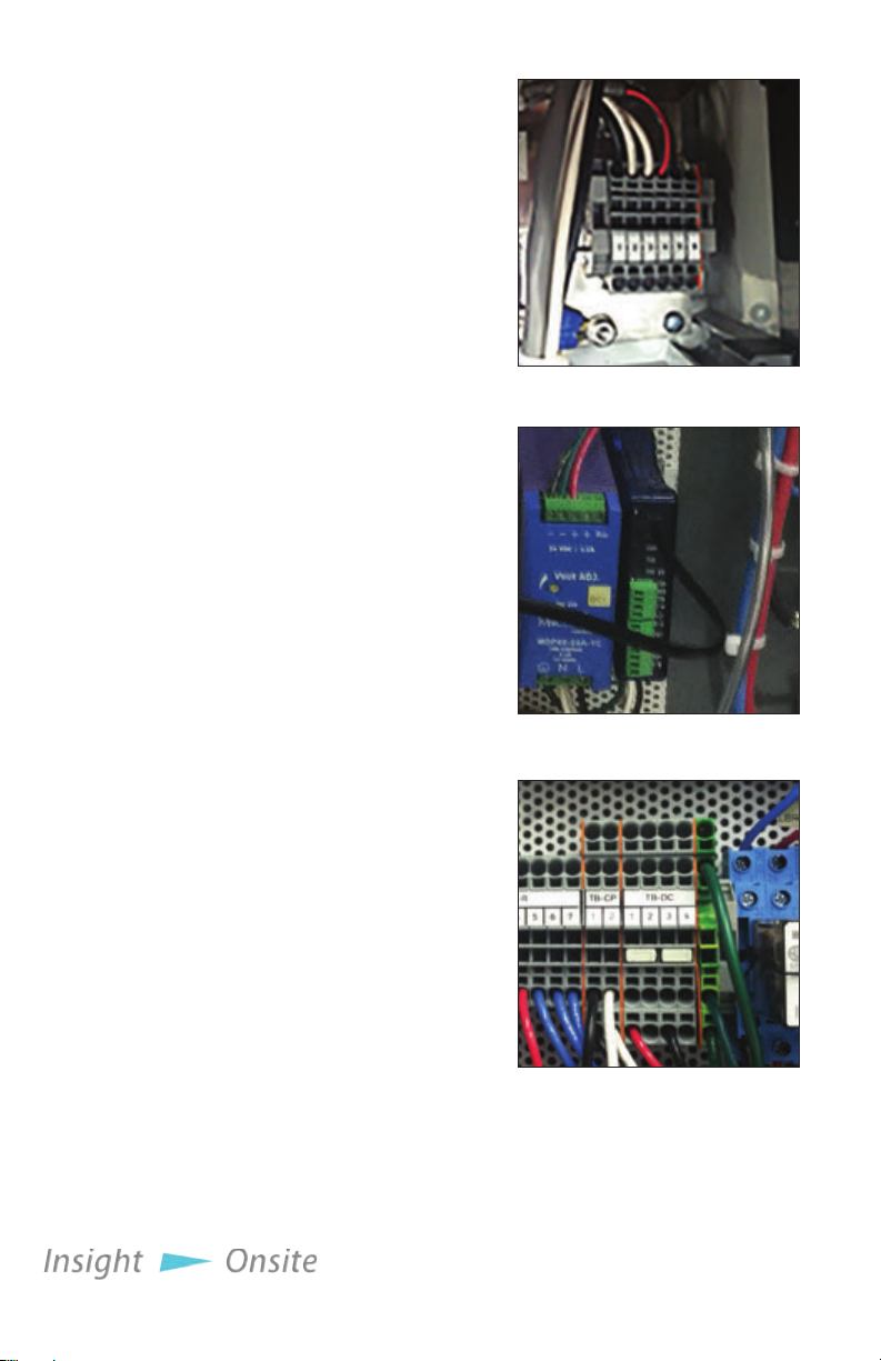
B. Using a copper wire,
14AWG or larger,
rated at 60C or
higher, connect the
HMI’s TBH 1 to the
load bank’s TB-DC
1 terminal and the
HMI’s TBH 2 to the
load bank’s TB-DC 3
terminal (see Figure 8
TB-DC).
Figure 7 TB-DC
Installaon — 9
Page 16

load dump
inStallation
If the Load Dump
feature is desired, remove
the factory-installed
jumper at TB-R 1–2 and
connect customer-supplied
Load Dump contacts to
TB-R 1–2 (See Figure 9
Load Dump Jumper). To
dump the load, open the
customer-supplied contact.
To enable load, close the
customer-supplied contact.
Load Dump Jumper
Figure 8
10 — Installaon
Page 17
Current
t
ranSformer
inStallation
The current
transformers
must be
placed and
oriented
correctly to
ensure they
accurately
detect the
current. The
rst current
transformer
must be
installed on
Phase A, and
the second
must be
installed on
Phase C.
If your load bank is
equipped with Metering,
Automatic Mode or
Regenerative Mode options,
you will have to install
current transformers on
your power cable.
• For metering mode,
install the current
transformers on the load
bank leg of your power
system (see “Figure 13
Current Transformer
placement for Metering”
on page 12.)
• For Automatic/
Regenerative Mode,
install the current
transformers on the power
source leg (see “Figure 14
Current Transformer
placement for Auto/
Regen. Mode” on page
12.)
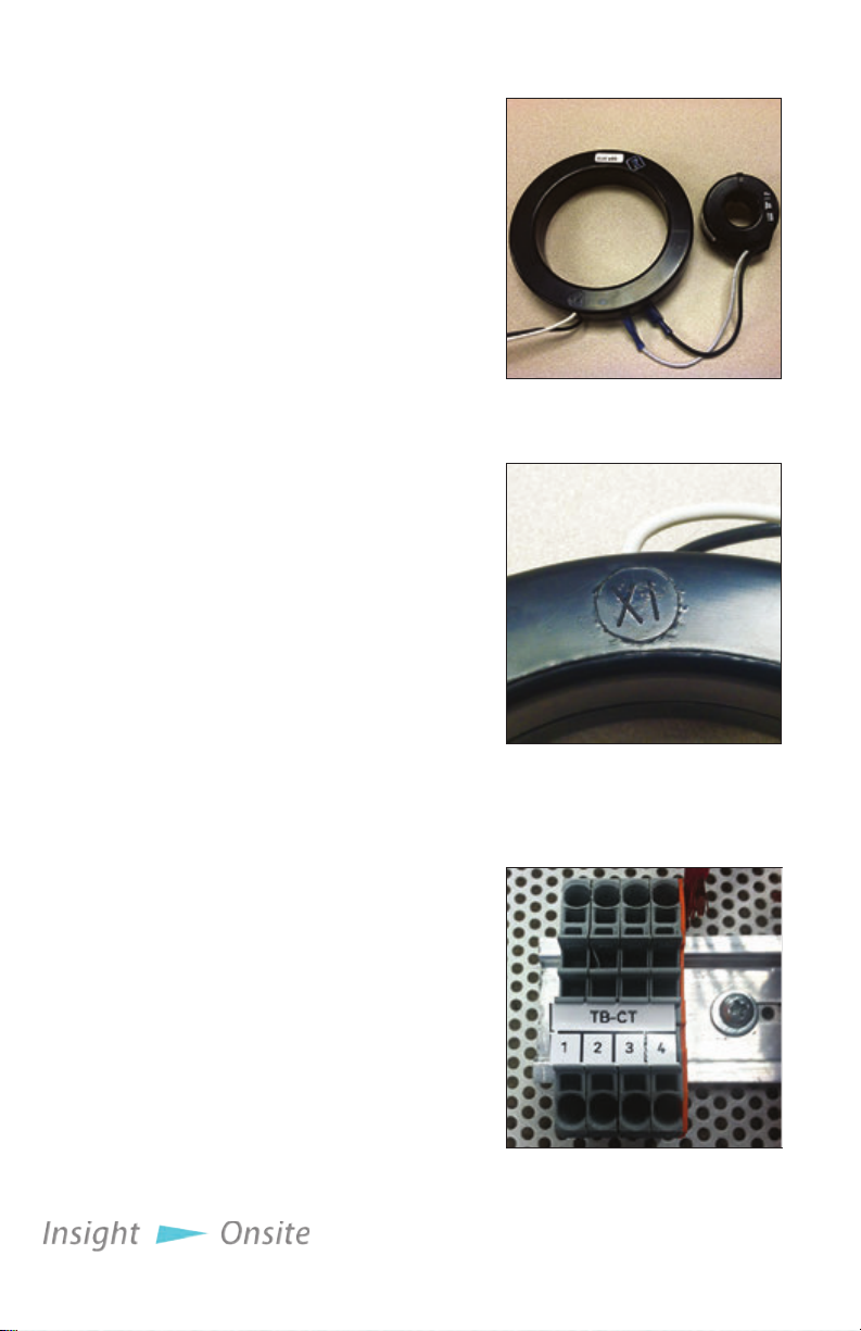
Orient the current
transformers so that the XI or
HI on each ring is facing the
power source (see Figure 11
CT Orientation.)
When the current
transformers are installed,
connect them to the load
bank by connecting the
white wire of the current
transformer on Phase A to
TB-CT 1 and the black wire
to TB-CT 2. If a second
current transformer is
installed on Phase C, connect
its white wire to TB-CT 3
and its black wire to TB-CT
4 (see Figure 12 TB-CT.)
Make sure the XI or HI on the
ring faces the power source.
Figure 9
Current Transformers
Figure 10
CT Orientation
Figure 11 TB-CT
Installaon — 11
Page 18

Figure 12
Current
Transformer
placement for
Metering
Figure 13
Current
Transformer
placement for
Auto/Regen.
Mode
e rst current transformer must be installed on Phase A, and the second must be
installed on Phase C.
12 — Installaon
Page 19

modbuS
inStallation
e Saturn load bank
supports the Modbus
protocol, implemented
either as RS485 or TCP/
IP (which is an optional
upgrade).
To implement Modbus
control and monitoring,
connect the load bank to
your facility’s systems as
follows:
For RS485:
Figure 15 Modbus Serial
1. Connect the RS485+ line
to TB-COM 1
2. Connect the RS485- line
to TB-COM 2
3. Connect the wire
shielding to TB-COM
Terminal 3
For Optional Modbus
TCP/IP
Figure 14 TB-COM
Converter
1. Plug a CAT5e cable
into the ethernet jack
on the MODBUS Serial
Converter (see Figure 16 Modbus Serial Converter.)
e Polaris Modbus control set is implemented as detailed in
“Appendix B — Modbus controls” on page 41
Installaon — 13
Page 20

Heater
inStallation
Saturn load banks are
equipped with space heaters
for cold weather operation
and to prevent condensation,
which can damage the
unit. e heaters require
a dedicated power source
independent of control
power at all times to prevent
startup failure due to cold
environments.
To run power to the
heaters:
1. Run a 120V, 15A, 1-phase power cable into the control panel.
2. Connect the Line leg of the power cable to SH-1
3. Connect the Neutral leg of the power cable to SH-2
4. Connect the Ground leg of the power cable to SH-3
e heaters are set at 50 degrees Fahrenheit. If a dierent
temperature is required, adjust the red thermostat on the front
of the heater.
Figure 16 TB-SH
14 — Installaon
Page 21

bmS/baS
inStallation
e Polaris provides a
set of Remote Signal Dry
Contacts, which allow you to
integrate the load bank into
your Building Management
System (BMS) or Building
Automation System (BAS)
e dry contacts provide an
alarm message, letting you
know if the load bank has
failed.
To enable BMS/BAS
functionality, wire three
cables to TBR 5-7. Continuity between TBR 5 and TBR 6 indicate
normal load bank operation, and continuity between TBR 5 and
TBR 7 indicate load bank failure.
Figure 17 TBR
Installaon — 15
Page 22

5 SETUP
Saturn load
banks feature
a power
outlet in the
control panel
for your use.
This outlet is
limited to 2
amps.
general
S
ettingS
e Saturn load bank
oers a number of
conguration options
through its setup screens.
You can access the setup
screens by pressing “F4 Setup” or the F4 function
ke y.
At the main setup screen,
you are presented with four options:
1. General Settings
2. Automatic Mode Settings
3. Test Mode (Intended only for Simplex engineers)
4. Factory Setup (Intended only for Simplex engineers)
You can access General Settings and Automatic Mode
Settings by pressing their respective buttons.
General Settings presents
three elds:
1. Cooldown Delay (sec)
2. Intake Temp Warning (F)
3. Exhaust Temp Alarm (F)
Figure 18 Setup Screen
Figure 19 General
Settings
Cooldown
Delay should
not normally
be changed.
automatiC
m
ode
16 — Setup
Cooldown Delay
determines how long the
load bank fans will continue
running aer an operation has been concluded. Intake Temp
Warning determines at what temperature the load bank will
present a warning that the air being used for the forced air
cooling system is too hot.
Exhaust Temp Alarm determines how hot the exhaust must
be before the load bank will trigger an Exhaust Temp High alarm
and remove the load. is and Intake Temp Warning may need
to be changed at installation, depending on the climate.
Automatic Mode Settings specify the operation of Automatic/
Regenerative Mode. For information about how to set them up,
see “Setting Up Automatic Mode” on page 20.
Page 23

6 OPERATING INSTRUCTIONS
pre-operation
CHeCkS
Saturn load
banks feature
a power
outlet in the
control panel
for your use.
This outlet is
limited to 2
amps.
1. Start the generator or
source being tested.
2. Ensure the load bank’s
Fan/Control Power
Disconnect Switch,
located on the unit’s door,
is in the on position (see
Figure 21 Fan/Control
Power Disconnect
Switch.)
3. Check the load bank’s
intake areas, located on
the bottom of the unit, to
ensure that the vents are
not blocked by paper or
other debris that would
prevent the cooling fan
from pulling in air.
4. On the HMI, turn on the
load bank by pressing the
Control Power button in
the upper le corner of
the screen (see Figure 22
Control Power Button.)
5. Listen to the load
bank’s fan to ensure it is
operating normally.
Figure 20 Fan/Control
Power Disconnect Switch
Figure 21 Control Power
Button
Figure 22 HMI - Manual
Mode
Setting up tHe
teSt
When the fan is running
properly, you are ready to
begin testing.
Press the F1 function
key or “F1 - Manual Mode”
on the screen to bring up
Manual Mode (See Figure
23 HMI - Manual Mode). In
the upper right area of this
screen is a display indicating
the load to be applied,
measured in kilowatts. To
change this value, touch the
Figure 23 HMI -
Numeric keypad
Operang Instrucons — 17
Page 24

number and enter the new
value on the numeric keypad
that appears (see Figure 24
on page 17). Enter the
desired value and press the
↵ button to return to the
previous screen, or press
“E” to return to the main
screen without changing the
value.
In the lower right quadrant of the screen is the KW Jog
value. is indicates by how many kilowatts you will increase
or decrease the load by pressing the “-” and “+” buttons,
respectively. To change this value, press the number and enter
your choice using the numeric keypad.
Figure 24 HMI
Information
teSting
operation
metering (if
equipped)
SHutdown and
Cooling
To begin testing, press the “Master Load” button. is will
activate the load bank and begin applying the load displayed
in the upper right area of the screen. To quickly decrease or
increase the load, press the “-” and “+” buttons.
If you have purchased the
metering upgrade, pressing
the F3 function key or “F3 Information” on the screen
while the test is running will
bring up the metering screen
(see Figure 26). Here you can
monitor the voltage, current,
load applied to the source,
and the frequency of the electricity. is screen also displays the
temperatures registered by the load bank’s three sensors.
If any of three voltage or current values are signicantly dierent
from the other two, check the load bank for a blown fuse. If no
blown fuse is found, contact Simplex service at 800-637-8603, ext. 4.
Pressing “Alarm History” on this screen will bring up a list of
registered alarms (See Figure 27.)
When the test is complete, press the Master Load button then
the Control Power button to remove the load from the test source.
e load bank’s fan will continue running for the duration of the
cooldown delay (see page 16 for more information).
Figure 25 Alarm History
18 — Operang Instrucons
Page 25

7 AUTOMATIC MODE
overview
e Saturn load bank can
Figure 26 Setup Screen
be equipped with an optional
automatic mode, which will
extend your generator’s life
by protecting it against wetstacking and reverse current.
Automatic Mode adds
load when the load bank
detects that your generator
isn’t operating in its optimal
range.
When your load bank
is installed, a set of current
transformers will be installed
on your generator’s power
lines to monitor the load on
your system. When the load bank detects that the power draw
has fallen below a preset range, it begins adding load until the
draw on the generator is within the designated range. Should the
load bank determine that the power draw has increased beyond
Figure 27 Automatic
Mode Setup
10%
10%
Figure 28 Automatic/Regenerative Mode
In this illustration, the load bank has been set up for an
800KW generator. e Target Load is set at 560KW, with 10%
Max Deviation. So long as the load remains in the green area,
the load bank will not add or drop load. But if the load moves
into the red area, the load bank will adjust the load to move it
back into the green.
Automac Mode — 19
Page 26

the preset maximum value,
it begins removing load until
the draw is back within the
designated range.
Figure 29 Automatic
Mode Running
Setting up
a
utomatiC
m
ode
The values
you will need
to set up
this mode
are specic
to your
generator.
For example,
if you have an
800 kilowatt
generator
with a 60% to
80% optimal
operating
range, you
might set
Target Load
to 560 (which
is 70% of its
capacity)
and Max
Deviation to
10%.
Before you activate
Automatic Mode, you must
congure the load bank to
interact with your generator.
Enter the Automatic mode
setup screen by pressing the “F4 Setup” button on the screen or
the F4 function key to reach the Setup Screen, then pressing the
Automatic Mode Settings button (see “Figure 28 Setup Screen” on
page 19.)
On the setup screen will be ve options specic to Automatic
Mode. (See “Figure 29 Automatic Mode Setup” on page 19.)
• Target load (KW): Sets the target load you want on your
generator, measured in whole kilowatts.
• Max Deviation (%): Determines how far above and below your
target load is acceptable, measured in whole percentage points.
• Step Up Delay (sec): Determines how fast the load bank will
add sequential load steps, measured in whole seconds.
• Step Down Delay (sec): Determines how fast the load bank
will remove sequential load steps, measured in whole seconds.
• Startup Delay (sec): Determines how long the load bank will
wait before adding load once the power draw has dropped below
the lower limits established by Target Load and Max Deviation,
measured in whole seconds.
To change any of the values, press the value and a numeric
keypad will come up. Use it to enter a new value the same way you
would enter a load to apply. (See page 17 for more information
about using the numeric keypad.)
entering
a
utomatiC
m
ode
20 — Automac Mode
When your load bank is congured, return to the main screen
by pressing the “Back” button. From the Main screen, press the
“F2 - Auto” button or the F2 function key to enter the Automatic
Mode screen (See Figure 31 Automatic Mode Running.)
On the Automatic Mode screen, press the “Auto Mode”
switch. Once this mode is enabled, the load bank will monitor
your generator and step the load up or down as necessary.
Once congured and enabled, your load bank can remain in
Automatic Mode indenitely.
Page 27

8 MAINTENANCE/TROUBLESHOOTING
general
maintenanCe
eaCH
o
peration
Remove all
power from
the load bank
before
servicing the
unit.
every 6
m
ontHS
e load bank has been designed to require minimum
maintenance. All components have been chosen for a long,
reliable life. Two basic intervals of maintenance are required:
each operation and every 6 months.
• Check the air intake screens and louvers, fan and cooling
chamber, and exhaust openings for any obstructions or
foreign objects.
• Check fan blades for stress fractures.
• Check the exhaust vent for obstructions
• Check the load branches for blown fuses or opened load
resistors.
To check the fuses or load resistors, operate the load bank
from a balanced 3-phase source and check the three line
currents. e three current readings should be essentially the
same. If a sizable dierence is noted, one or more load fuses or
load resistors may have malfunctioned.
Check the tightness of the electrical connections. e
expansion and contraction caused by load bank operation may
cause loose connections. For a detailed inspection guide, see
“Primary Inspection” on page 6.
Maintenance/Troubleshoong — 21
Page 28

trouble
SHooting
Although Saturn load banks are designed with trouble-free
operation in mind, some problems can arise. Please consult the
following table for solutions to the most common issues before
contacting a Simplex service representative.
Table 1 Troubleshooting
Problem Solution
Load bank
wired to
source but
won’t turn on
Load bank
overheating
HMI not
displaying data
Ensure load bank is wired to source correctly
Check for and replace any blown fuses
Tighten any loose relays, contactors, lugged wires, etc.
Clear intake and exhaust vents of any debris
Ensure load bank was not installed too close to generator
or any other source of exhaust
Ensure load bank was installed in a location that allows
sucient cool air intake
Make sure ambient temperature isn’t too high to allow for
cool air ow
Ensure HMI power connections are wired correctly
Check HMI serial cable connections
22 — Maintenance/Troubleshoong
Page 29

9 ALARMS AND WARNINGS
Saturn load banks are protected by four types of sensors.
1. Intake temperature, which checks the incoming air to ensure
the load elements can be adequately cooled.
2. Exhaust temperature, which checks the air temperature
coming out the load bank.
3. Fan pressure, when ensures the fan blades are forcing air into
the load element chamber.
4. Fan current, which ensures the fan motor isn’t overloaded or
jammed.
alarmS
Unresolved
cooling
issues may
result in
damage to
the load
bank.
warningS
e Saturn load bank’s HMI features ve status areas:
• Motor: Indicates the status of the cooling fan motor
• Fan: Indicates whether the fan is blowing air into the element
chamber
• Intake Temp: Indicates status of incoming cooling air
• Exhaust Temp: Indicates status of load bank’s exhaust
• Load Dump: Indicates whether the load dump feature has
been activated
With the exception of Intake Temp, any failure state will cause
the unit to dump the load until the problem is xed.
e load bank will alert you to alarms by turning the status
areas for the alarm on the home screen from green to red and
displaying the alarm signal in white text.
e Saturn features one warning: Intake Temp High. When
this warning is triggered, the Intake Temp status area will turn
yellow.
Saturn load banks do not dump load when a warning is
triggered, but the problem should be investigated as soon as
possible.
Alarms and Warnings — 23
Page 30

Table 2 Troubleshooting alarms
Alarm Cause Solution
Motor
Fan
Intake Temp
Fan blades blocked Clear obstruction
Intake vents blocked
by debris, paper, etc
Fan blades have come
loose from sha
Intake vents blocked
by debris, paper, etc
Load bank pulling
in exhaust from
generator, etc.
Insucient airow
Ambient temperature
too high
Clear intake vents
Tighten fan blade hub.
Clear intake vents
Ensure load bank was
not installed too close
source of exhaust
Ensure load bank has
access to sucient
cool air intake
Conduct operation on
cooler day, if possible
Exhaust Temp
Load Dump
24 — Alarms and Warnings
Air not being forced
over load elements
Load dump switch
activated
Load dump jumper
fell out of TB-LD 1-2
Ensure fan and fan
motor are working
correctly and rotating
in correct direction
Deactivate load dump
switch
Replace load dump
jumper
Page 31

APPENDIX A PARTS LISTINGS
Figure 30 Right Subpanel Layout
Opon D - Automaon/
Metering page 26
Opon E - Communicaon
(TCP/IP Data Logging)
page 27
PLC
page 28
Control Relays
page 30
Terminal blocks/Service Outlet
page 32
Opon 010 - Space Heaters
page 34
Parts lisngs - 25
Page 32

Table 3 Option D - Automation/Metering
Label Description Part Number
TB-M 1
TB-M 2
TB-M 3
TB-M 4, 6
TB-M 5, 7
DMP1
26 - Parts lisngs
Terminal Block, 4
Connections, Black
Terminal Block, 4
Connections, Red
Terminal Block, 4
Connections, Blue
Terminal Block, 4
Connections, Grey
Terminal Block, 4
Connections, Green
Digital Metering
Package, RS232
25678547
25678546
25678557
25678536
25678537
24345050
Page 33

Table 4 Option B - Communication (TCP/IP Data Logging)
Label Description Part Number
Modular Controller
CM1
and Protocol
Converter
24955043
NS1
Ethernet Switch, 5
Port, Unmanaged
24955074
Parts lisngs - 27
Page 34

Table 5 PLC Component list
Label Description Part Number
PLC1
EX1
EX2
DC1
CM2
TB-COM1-6
28 - Parts lisngs
PLC 24955113
8PT Relay Output
Module
4PT ermocouple
Input Module
DC Power Supply,
60W, 24VDC
RS232/RS485
Converter, RJ12 Port
Terminal Block,
Spring Type,
20A, 600Vac, 2
Connections, Grey
24955008
24955023
25457900
24953500
25678532
Page 35

Parts lisngs - 29
Page 36

Table 6 Control Relays
Label Description Part Number
F4
F5
SR9
SR8
SR7
SR6
SR5
SR4
SR3
Fuse, 2A, 600V, Instantaneous 14014500
Fuse, 2A, 600V, Time Delay 14012000
Relay, 24VDC Coil, 3PDT 24827045
Relay, 24VDC Coil, 3PDT 24827045
Relay, 24VDC Coil, 3PDT 24827045
Relay, 24VDC Coil, 3PDT 24827045
Relay, 24VDC Coil, 3PDT 24827045
Relay, 24VDC Coil, 3PDT 24827045
Relay, 24VDC Coil, 3PDT 24827045
SR2
SR2
NOR1
NOR2
LBR1
30 - Parts lisngs
Relay, 24VDC Coil, 3PDT 24827045
Relay, 24VDC Coil, 3PDT 24827045
Relay, 24VDC Coil, 3PDT 24827045
Relay, Large, 24VDC Coil 24816000
Relay, Large, 24VDC Coil 24816000
Page 37

2A
Parts lisngs - 31
Page 38

Table 7 Terminal Blocks
Label Description Part Number
Terminal Block, Spring Type,
TB-CP 1-4
TB-C 14-26
TB-DC 1-2
TB-DC 3-4
TB-C 1-13
20A, 600Vac, 4 Connections,
Grey
Terminal Block, Spring Type,
20A, 600Vac, 2 Connections,
Grey
Terminal Block, Spring Type,
20A, 600Vac, 4 Connections,
Red
Terminal Block, Spring Type,
20A, 600Vac, 4 Connections,
Black
Terminal Block, Spring Type,
20A, 600Vac, 4 Connections,
Grey
25678536
25678532
25678546
25678547
25678536
TB-R 1-2
TB-R 3-6
CO1
32 - Parts lisngs
Triple Deck Terminal Block,
Spring Type, 24A, Blue
Terminal Block, Spring Type,
20A, 600Vac, 4 Connections,
Grey
Outlet, 120Vac, DIN Rail
Mount, 15A
25678550
25678536
25629900
Page 39

Parts lisngs - 33
Page 40

Table 8 Option 010 - Space Heaters
Label Description Part Number
TB-SH 1-3
HF1
HTR1
Terminal Block, 2
Connections, Grey
Fuse, 7A, Time Delay 14039000
Enclosure Heater,
120Vac, 550W w/
ermostat
25678532
25309211
34 - Parts lisngs
Page 41

Phase C
page 39
Subpanel
Phase A
page 37
Phase B
page 38
Load
control
terminal
blocks
page 40
Parts lisngs - 35
Page 42

Table 9 Center Subpanel
Label Description Part Number
RC 1-6
RC5-15
FMC1
OLR1
CB1
T1
Subpanel
Contactor, 40A
Resistive
Contactor, 65A
Resistive
Contactor, 40A
Resistive
Overload Relay, 5.7-
18.9A
Circuit Breaker, 15A
Trip
Transformer, 300VA,
480/240:240/120Vac
Subpanel, Saturn,
Rear
13011040
13011065
13011040
24827710
12046615
25457650
PRT-00025390
36 - Parts lisngs
Page 43

Table 10 Phase A Detail
Label Description Part Number
Bus Bar (vertical)
RF4
RF7-34
Bus Bar (horizontal)
RF1
Bus Bar, Single Pole,
750A, Phase A
Fuse, 35A, Class T,
Fast Acting
Fuse, 70A, Class T,
Fast Acting
Bus Bar, Nept/Mars,
0.250” x 4.00” x10.50”
Fuse, 35A, Class T,
Fast Acting
60044465G
14074000
14087000
60063693
14074000
Parts lisngs - 37
Page 44

Table 11 Phase B Detail
Label Description Part Number
Bus Bar (vertical)
RF5
RF8-35
Bus Bar (horizontal)
RF2
38 - Parts lisngs
Bus Bar, Single Pole,
750A, Phase B
Fuse, 35A, Class T,
Fast Acting
Fuse, 70A, Class T,
Fast Acting
Bus Bar, Nept/Mars,
0.250” x 4.00” x10.50”
Fuse, 35A, Class T,
Fast Acting
60044466E
14074000
14087000
60063693
14074000
Page 45

Table 12 Phase C Detail
Label Description Part Number
Bus Bar (vertical)
RF6
RF9-36
Bus Bar (horizontal)
RF3
Bus Bar, Single Pole,
750A, Phase C
Fuse, 35A, Class T,
Fast Acting
Fuse, 70A, Class T,
Fast Acting
Bus Bar, Nept/Mars,
0.250” x 4.00” x10.50”
Fuse, 35A, Class T,
Fast Acting
660044467G
14074000
14087000
60063693
14074000
Parts lisngs - 39
Page 46

Table 13 Load Control Terminal Blocks
Label Description Part Number
F1-2
F3
TB-L 1
TB-L 2
TB-L 3
TB-L 4-19
40 - Parts lisngs
Fuse, 1.5A, Time
Delay
Fuse, 3.5A, Time
Delay
Terminal Block, 4
Connections, Black
Terminal Block, 4
Connections, Red
Terminal Block, 4
Connections, Blue
Terminal Block, 2
Connections, Grey
14009500
14019775
25678547
25678546
25678557
25678532
Page 47

APPENDIX B MODBUS CONTROLS
Table 14 Modbus Controls (Read/Write)
Name Type
Activate
Fan
Apply Load
Cancel
Cooldown
KW To
Apply
Function
Address
Code
Coil 01 16586
Coil 01 16704
Coil 01 16487
Floating Point 03 28911
Modbus controls - 41
Page 48

Table 15 Modbus Indications (Read only)
Name Type
Exhaust Alarm
Fan Failure
Alarm
Load Dump
Activated
Fan Running
Applied Load
Regulate Mode
Active
Regenerative
Sensing Mode
Active
Function
Code
Coil 01 16484
Coil 01 16485
Coil 01 16486
Coil 01 8193
Floating
Point
Coil 01 16705 (a)
Coil 01 16706 (b)
03 29077
Address Notes
Vab
Vbc
Vac
(a) Load Banks with Automatic Load Regulation Only
(b) Load Banks with Regenerative Power Sensing Only
(c) Load Banks with Any Automation Option Only
42 - Modbus controls
Floating
Point
Floating
Point
Floating
Point
03 28673 (c)
03 28675 (c)
03 28677 (c)
Page 49

Table 15 Modbus Indications (Cont.)
Name Type
Va
Vbc
Vc
Ia
(a) Load Banks with Automatic Load Regulation Only
(b) Load Banks with Regenerative Power Sensing Only
(c) Load Banks with Any Automation Option Only
Floating
Point
Floating Point 03 28681 (c)
Floating Point 03 28683 (c)
Floating Point 03 28685 (c)
Function
Code
03 28679 (c)
Address Notes
Modbus controls - 43
Page 50

modbuS
C
ontrol
d
ireCtionS
1. Ensure that “Regulate Mode Active” (16705) and
“Regenerative Sensing Mode Active” (16706) are OFF,
indicating that the load bank is ready for Modbus Control
2. Turn “Activate Fan” (16586) ON to energize the cooling fan
3. Verify fan is running by checking that “Fan Running” (8193
is ON
4. Write the desired amount of KW to apply to “KW To Apply”
(28911)
5. Turn “Apply Load” (16704) ON to energize the desired
amount of load
6. Verify applied load by reading value at “Applied Load” 29077.
e load bank will apply as much load as possible to reach the
“KW To Apply” value, without exceeding it.
7. Monitor other values as desired.
8. Turn “Apply Load” o to de-energize the load
9. Turn “Activate Fan” OFF to stop the cooling fan. Load bank
will continue to operate cooling fan for Cooldown Time set
on HMI.
10. Cooldown mode has ended and cooling fan has stopped
when “Fan Running” is OFF
11. Cooldown mode can be stopped by writing ON then OFF to
“Cancel Cooldown” (16487)
44 - Modbus controls
Page 51

APPENDIX C PRODUCT WARRANTY
SIMPLEX, Inc., warrants the industrial electrical control, test and accessory equipment
and parts and accessories thereof to be the kind and quality described in SIMPLEX’s
specications and to be free from defects in material or workmanship under normal
service, its obligations under this warranty being limited to repairing or replacing, at its
option, any part or parts which shall, within twelve (12) months from date of shipment
from its factory, as indicated by serial date code on the nameplate or sales records, be
returned to SIMPLEX or an authorized SIMPLEX repair station, with transportation
costs prepaid, and which its examination shall disclose to its satisfaction to have been
thus defective.
e provisions of this warranty shall not apply to any equipment, part or accessory
which
(a) has been improperly specied by buyer;
(b) has been improperly stored or handled prior to placing in service;
(c) has been improperly mounted or connected;
(d) has not been operated within specications stated on its nameplate, label or
placard;
(e) has not been properly maintained;
(f) parts supplied by buyer for inclusion in nished equipment are not covered by
this warranty;
(g) components or assemblies specied by buyer with no substitution permissible
that are not normally used by SIMPLEX.
SIMPLEX reserves the right to reject warranty claims of any kind against assembled
equipment, parts or material for which SIMPLEX has not received payment in full.
Should buyer, at his own risk, elect to replace defective equipment or parts in the
eld rather than return equipment to SIMPLEX’s factory or authorized repair station,
SIMPLEX will supply and invoice parts at normal prices upon receipt of buyer’s bonade purchase order. Defective equipment or parts returned for in-warranty crediting in
exchange for replacement parts must be returned within 45 days from date of shipment
of replacement in order to qualify for warranty consideration. Defective equipment or
parts returned aer 45 days may be subject to a restocking charge of 20% or a minimum
charge of $50.00, whichever is greater.
is warranty is in lieu of all other warranties, express or implied, and all other
obligations or liabilities on the part of SIMPLEX, and SIMPLEX neither assumes nor
authorizes any other person to assume for it any other liability in connection with any
such electrical control, test or accessory equipment or accessories or parts.
Product Warranty - 45
Page 52

WE WELCOME YOUR FEEDBACK!
Simplex designs and manufactures Load Banks and
Fuel Supply systems for power generation and liquid
automation. Simplex is certified to ISO 9001:2015.
Used world-wide for mission critical environments in
manufacturing, technology, transportation, hospitals,
schools, public utilities and the U.S. military,
Simplex products provide solutions meeting exact
requirements, from the simplest testing and proving
equipment for backup generators to custom-designed
and engineered mission-critical fuel systems. At
Simplex, we are experts at building products that meet
our customers’ exact requirements. For a complete
listing of Simplex products visit
www.simplexdirect.com.
Simplex welcomes your questions, comments,
suggestions, compliments, and complaints as a way to
continuously improve our service to you.
Please call us at 800-637-8603 (24 hours a day)
or visit www.simplexdirect.com.
Page 53

LOAD BANK RENTAL AND SERVICE CENTERS
Simplex Onsite can place Load Banks, Cables, Transformers, and Fuel Polishers rentals as well as service technicians at your ngerps anywhere in the
United States quickly and cost eecvely.
For informaon call 855-767-5483 or visit www.simplexonsite.com.
COLORADO
Serving Colorado, Idaho, Montana, Nevada, Utah and Wyoming
GEORGIA
Serving Alabama, Florida, Georgia, North Carolina and South Carolina
ILLINOIS
Serving Illinois, Indiana, Kentucky, Michigan, Missouri and Tennessee
MASSACHUSETTS
Serving Conneccut, Delaware, Maine, Maryland, Massachuses, New
Hampshire, New Jersey, New York, Pennsylvania and Vermont
MINNESOTA
Serving Iowa, Minnesota, North Dakota, South Dakota and Wisconsin
OHIO
Serving Indiana, Michigan, Ohio, Pennsylvania (western) and West Virginia
TEXAS
Serving Arkansas, Louisiana, New Mexico, Oklahoma and Texas
Page 54

Simplex, Inc.
5300 Rising Moon Road
Springfield, IL 62711-6228
(800) 637-8603
www.simplexdirect.com
 Loading...