

Page 1
HYDRAULIC & MECHANICAL POWER
E
Q
U
I
P
M
E
N
T
S
E
R
V
I
C
E
A
S
S
O
C
I
A
T
I
O
N
R
E
B
U
I
L
D
E
R
S
O
F
T
O
O
L
S
&
E
Q
U
I
P
M
E
N
T
U
S
A
M
E
M
B
E
R
C
A
N
A
D
A
PAM & PGM SERIES
PRO - MAG
40 & 50 SERIES
AIR & GASOLINE POWER PUMPS
T
R
S
Y
N
I
G
N
I
V
R
E
SINCE - 1899
S
Te
m
U
D
pl
e
t
on
Q
U
W
I
T
H
P
R
I
D
E
.
c
n
I
.,
Co
y&
Ke
nl
Y
T
I
A
L
Operating & Maintenance Instructions
For 1
1/2 H.P. Air & Gasoline Pumps
and 8 H.P. Gasoline Pump.
1.5 H.P. Air Pumps
3.5 and 8 H.P.
Gas Pumps
Part Sheet #: 54393
Revised: 12-01
The world's most complete line of industrial, hydraulic and
mechanical lifting and positioning equipment.
SIMPLEX DIVISION OF TEMPLETON, KENLY & CO., INC.
2525 Gardner Road • Broadview, Illinois 60155 • (708) 865-1500 / Fax (708) 865-0894
www.tksimplex.com
Page 2

SAFETY
1-1. Working Pressure
The pump's maximum working pressure is 10,000 PSI (700 kg/cm
2
). Make sure
that all hydraulic equipment used with this pump are rated at 10,000 PSI operating pressure.
1-2. Hydraulic Connections
Never disconnect or connect any pressurized hydraulic hoses or fittings.
or open all hydraulic controls several times to assure that the system has been depressurized.
If the system includes a gauge, double check the gauge to assure pressure has been released.
When making connections with quick disconnect couplings,
are fully engaged
tightened and leak free.
CAUTION: Loose or improperly threaded fittings can be potentially dangerous if pressurized, however, severe over tightening can cause premature thread failure. Fittings need to be
tightened secure & leak free. Never hold or stand directly in line with any hydraulic connections while pressurizing. Never grab, touch or in any way come in contact with a hydraulic
!
pressure leak. Escaping oil can penetrate the skin and a serious injury can result.
Do not subject the hose to potential hazard such as sharp surfaces, extreme heat or heavy
*
impact. Do not allow the hose to kink & twist. Inspect each hose for wear before it is used.
. Threaded connections such as fittings, gauges, etc. must be securely
make sure the couplings
Shift,
Electrical Power for Solenoid valves (normally 12 or 24 volts)
1-3.
1. CHECK FOR PROPER ELECTRICAL SUPPLY BEFORE CONNECTING.
2. DO NOT OPERATE IN AN EXPLOSIVE ATMOSPHERE OR IN THE PRESENCE OF
CONDUCTIVE LIQUIDS.
a. Do not use a power or extension cord that is damaged or has exposed wiring.
b. Solenoids come equipped with a three prong grounding type plug to fit the proper
grounded type electrical outlet. Do not use a two prong ungrounded extension cord as the
pump's motor must be grounded.
Jacking Safely
1-4.
You must know the weight of what you intend to lift and choose a ram with at least 10%
more capacity.
The ram should be placed on a
solid foundation so that the base of the ram is fully
supported. The load must be centered on the ram, or equally distributed on multiple rams. Off center loading can result in the ram slipping out and loss of the
load.
Never crawl or place any part of your body under any load at any time. Insert
blocking or cribbing under the load as you lift. Hydraulic rams are meant for lifting
only and should not be used to support the load for any period of time.
You should obtain and be familiar with the American National Standards Institute rules that
apply to hydraulic rams and jacks (ANSI B30.1).
- 2 -
Page 3

INSTRUCTIONS BEFORE USE
Read carefully. Most malfunctions in new equipment are the result of improper operation
and/or improper set-up assembly.
Preparation: Remove pump from shipping container -- but do not remove any plugs or
valves until the unit is ready to be fully assembled to prevent dirt or foreign matter from
contaminating system.
Inspection: Visually inspect all components for shipping damage. If any damage is found,
notify carrier immediately.
Electrical Connections: Solenoid valves only.
2-1.
Air Connections for AIR POWER PUMPS: Use only clean, dry, well lubricated air.
Gasoline Motor Oil and Fuel:
1. Above 32 degrees Fahrenheit use S.A.E. 10 W 30 (Motor only )
2. Below 32 degrees Fahrenheit use S.A.E. 5 W 20 (Motor only )
3. Oil sump capacity - -About 1.3 pints or check dip stick
4. Use clean, unleaded automotive gasoline ( without alcohol )
2-2. Hydraulic Connections:
Check hydraulic
located on reservoir plate. Oil level should be
oil level to prevent possible pump burnout. Open the red plastic fill plug
approximately 2" from top of reservoir
plate -- with cylinders retracted and motor off. Add Simplex oil as necessary. Do not
mix different grades of oil, or types of oil.
Make sure all desired gauge, valve, hose and quick coupler connections are tight and
secure before operating (See Section 1.2). The pumps pressure ports are 3/8 NPTF and are
located just below the control valve. (See Section 3-1).
The use of a
pumps and
Mounted on a gauge adapter between the pump and cylinder, the gauge permits the operator
to monitor loads on cylinders.
pressure gauge is strongly recommended for normal operation of these
required when the external adjustable relief valve pressures are changed.
Do not exceed rated capacity of equipment connected to pump. Where shock loading
or unsteady loads may cause overloading of cylinders, the operator must use larger capacity
cylinders to provide additional operating margin.
2-3.
Starting instructions ( Gasoline Motor )
• Hydraulic control valve in neutral ( center position ): • Throttle to choke position ( extreme
right ): Grasp STARTER HANDLE and pull rope out slowly to engagement: • Pull rope with
a rapid, continuous full stroke and let rewind slowly, and do not allow to snap back. • Move
the control lever to "HIGH SPEED" position then to "RUN" as the engine warms.
- 3 -
Page 4

OPERATING INSTRUCTIONS AT A GLANCE
Before Operating Pump:
1. If your pump is equipped with a SIMPLEX SOLENOID be sure the electrical connection
is grounded. Check that your power supply agrees with the requirements of the solenoid.
2. Use only cylinders, hoses and equipment rated at 10,000 PSI.
3. Make sure all hose and fitting connections are tight and secure. Hoses cannot be
kinked or twisted.
4. Oil level should be 1 to 2" from the top of the reservoir plate, with cylinders retracted
and motor off.
5. Never operate the pump with the directional control valve in advance or retract at
10,000 PSI without ram movement for more than 1 minute. Leaving the valve in the
advance or retract position without the rams piston rod moving will overheat the oil.
After Completing the Job:
1. Before disconnecting hoses, fittings, etc., first be sure the ram is retracted & unloaded,
then unplug the power cord and shift the hydraulic controls several times to release
system
pressure.
2. Store the pump in a clean, dry area.
Periodic Maintenance:
1. Completely change the hydraulic oil and clean the oil filter screen and magnet (located
in the reservoir) twice a year. (Use Simplex oil only, Model # AO1, 1 gallon). Change
the oil more frequently when used in extremely dusty areas or when the oil has been
overheated. Using oil other than Simplex Brand voids the pumps warranty.
2. Contact an AUTHORIZED SIMPLEX SERVICE CENTER if there are any problems with
the equipment.
- 4 -
Page 5
OPERATION
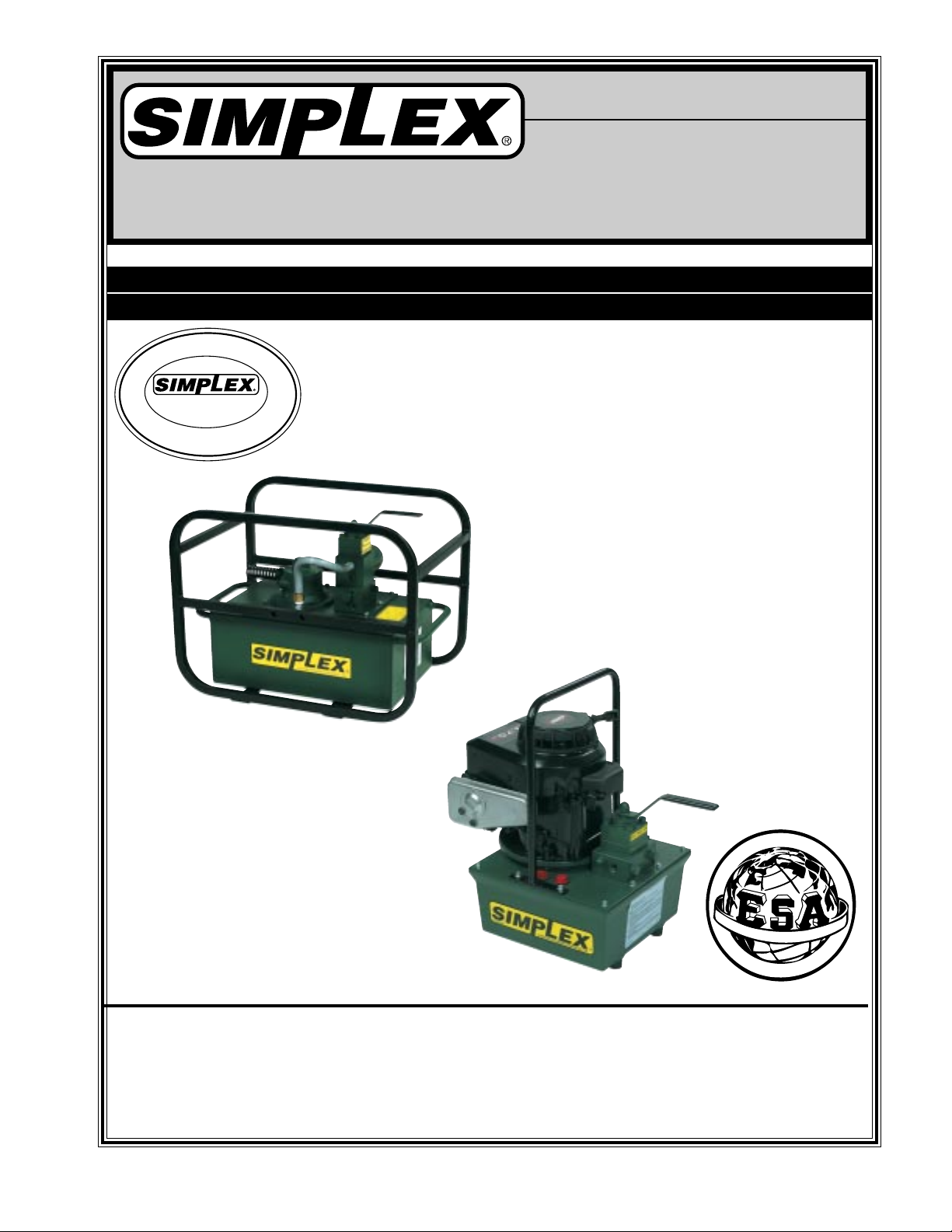
3-1. Control Valves:
a. 2-Way Valve for Single Acting Rams
To Advance.........turn lever to the right
& start motor.
To Hold................turn motor off.
To Retract............turn lever to the left.
b. 3-Way Valve for Single Acting Rams
To Advance..........push lever to right.
For Neutral/Hold...place lever in middle.
To Retract.............push lever to left.
c. 4-Way Valve for Double Acting Rams
Pushing lever to right directs pump output
to right-hand port.
Pushing lever to left directs pump output to
left-hand port.
Center position is neutral/hold. Pump
output is directed back to tank.
* Useable 3/8 NPTF port
*
Return ports
only.
(Marked T)
B *
B *
* A
* A
* A
* A
3-2.. Before starting pump,
prevent accidental lifting or moving of load. Start the pump and let the pump idle for a few
minutes.
Bleeding the Hydraulic System--air can be removed from the system by fully advancing
3-3.
and retracting the hydraulic cylinder several times with the pump elevated so its reservoir is
higher than the cylinder. Single-acting cylinder should be inverted, and double-acting on their
side with the coupling fitting up. When the trapped air is removed from the hydraulic circuit,
the cylinder will advance and retract smoothly. Sluggish cylinder action is usually the first sign
of air in the system.
3-4. Move lever to Advance position (as described above) to activate ram or cylinder. To hold
load, place lever into Neutral/Hold. Move lever to Retract position (as described above) to
release load.
3-5. Never operate the pump at 10,000 PSI without ram movement for more than 1 minute without
shifting the control valve to neutral.
place valve in Neutral/Hold position (as described above) to
Leaving the valve in the advance or retract posi-
tion without the piston rod moving will overheat the oil.
- 5 -
Page 6

MAINTENANCE
WARNING: THE ELECTRICAL POWER CORD MUST BE DISCONNECTED FROM ELECTRICAL OUTLETS BEFORE PERFORMING MAINTENANCE OR REPAIR
PROCEDURES.
4-1. Maintain Oil Level -- check hydraulic oil level every 30 hours of operation. Add Simplex oil
(Model # AO1 -- 1 gallon) when necessary. Oil level should be no more than 2" from top of
reservoir plate -- with cylinders retracted and motor off.
Completely change oil at least twice a year. The following conditions require more frequent
oil changes:
a. Rigorous duty, where oil temperature may reach 140 F.
b. High humidity environment and extreme changes in temperature that can result in con-
densation inside the reservoir.
c. Dirty or dusty environments that may contaminate the oil.
4-2. Clean Oil Filter Screen Once a Year
a. Loosen and remove reservoir plate bolts. Lift pump unit off the reservoir, being careful not
to damage the gasket.
b. Unscrew screen from bottom of pump unit and clean with nonflammable solvent.
c. Blow dry and reassemble.
4-3. Keep areas around pump unobstructed to provide good air flow around the motor and pump.
Keep the motor and pump as clean as possible.
4-4. Adjusting the External Relief Valve:
a. Install gauge and gauge adapter between pump and cylinder.
b. Remove cover to expose adjusting screw. Place valve lever in Neutral/Hold position and
start motor. Move lever to direct pump output to pressure port (Advance).
c. Insert allen wrench into adjusting screw in the hole on the lower left side of valve.
d. Turn adjusting screw clockwise to increase, or counter clockwise to decrease pressure .
(Do not exceed 10,000 PSI.)
e. Check valve setting by shifting the valve to advance and retract cylinder several times.
Maximum gauge reading should remain constant.
4-5. Flushing the Pump. If you suspect your pump has been contaminated or discover sludge or
other deposits on internal components, you should thoroughly flush the pump.
a. Remove the old oil from the reservoir, then thoroughly clean the reservoir and refill with a
clean, nonflammable flushing oil.
b. Reassemble the pump and motor to the reservoir.
c. Now run the pump in no load condition for 1 or 2 minutes maximum.
d. Unplug the pump and remove the motor and pump assembly again. Now drain the flush-
ing oil and reclean the inside of the reservoir. (Make sure flushing fluid is also drained
from pump assembly). Refill the reservoir with Simplex hydraulic oil and reassemble
the pump.
- 6 -
Page 7

TROUBLESHOOTING
If the procedures listed below do not remedy the problem -- the pump will require
service and should be taken to an authorized Simplex service center for repair
Problem Cause -- Solution
Sporadic Cylinder Action
Motor Will Not Start
Noisy Operation
Pump Oil is Over Heating
1. Air in the hydraulic system. See Sec. 3-3 for
correct bleeding procedure.
2. Check reservoir oil level.
Check manufacturer's operating instructions.
1. Air in system. (See Sec. 3-3 for bleeding
procedure).
2. Be sure the oil reservoir is filled to normal level.
3. Check all points where air might leak into
system.
1. Oil viscosity too high. Replace with Simplex #9.
2. Check for high pressure leakage on upper
pressure plate. (Leaking at plug).
3. Oil level is low. Fill reservoir to normal level, or
refit the pump with larger reservoir.
4. (See Section 3-5)
Pump Runs but Will Not Pump Oil
1. Pump is not primed. Run pump a few minutes
tipping from side to side.
2. Check to make sure that externally adjustable
relief valve set properly.
Check internal relief valve.
3. Damaged O-Rings. Take to nearest Simplex
service center for repair.
4. Defective control valve. (Troubleshoot
separately).
- 7 -
Page 8
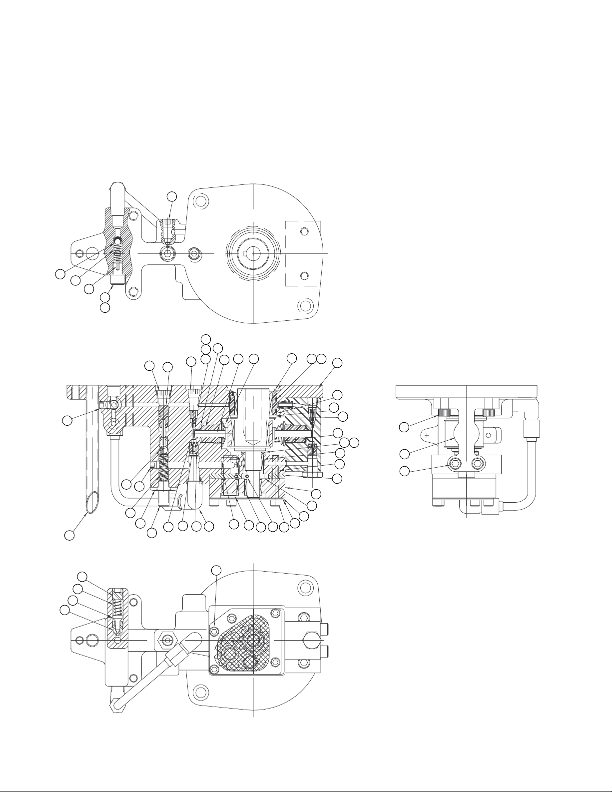
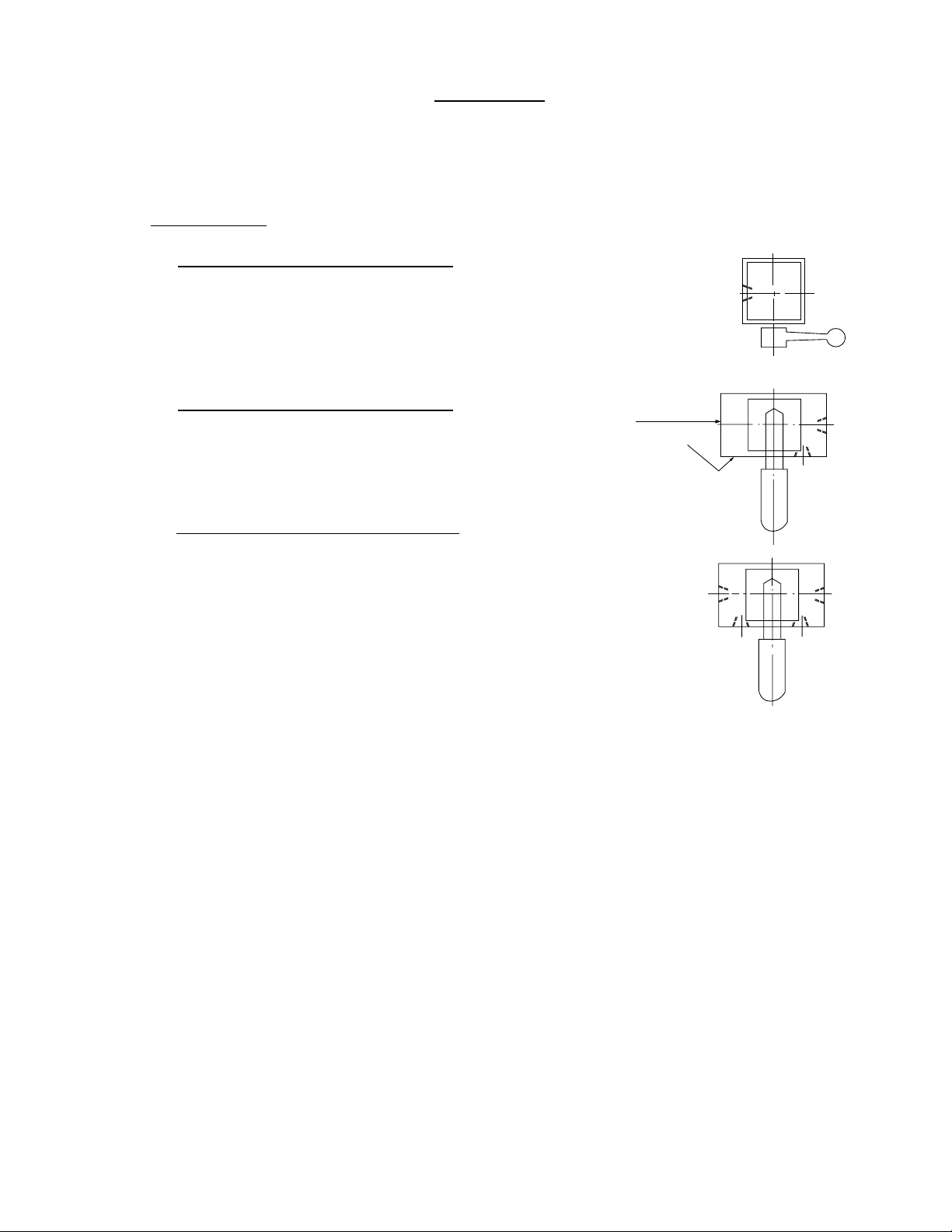
18948
PUMP ASSEMBIES 40 SERIES GAS PUMP
46
21
35
36
37
38
43
38
18
14
15
46
16
11
12 13
10
9 42
1
8
7
25
21
25
22
24
41
50
49
48
47
23
18
17
45
2019
34
29
18
44
28
30
33
32
6
5
3
4
2
31
26
27
55
53
54
- 8 -
Page 9

18948
PUMP ASSEMBIES 40 SERIES GAS PUMP
ITEM
1
2
3
4
5
6
7
8
9
10
11
12
13
14
15
16
17
18
19
20
21
22
23
24
25
26
27
28
29
30
31
32
33
34
35
36
37
38
41
42
43
44
PART NO.
68507
68360
66033
66474
68906
66106
66108
68829
56020322
68978
68945
67868
68340
68810
93950
68535
66043
90906
66046
68851
91701
68981
68242
68920
97641
68848
68849
68883
68850
68921
68894
68255
68927
89148
68225
81332
68226
85726
68569
69513
66042
68891
QTY.
1
1
1
2
1
1
1
1
2
1
1
1
1
1
1
1
1
5
1
1
2
1
1
1
2
1
1
2
1
1
2
4
1
1
1
1
1
2
1
2
1
3
DISCRIPTION
2 Piston Pump Body
Roller Bearing
Thrust Bearing
Race Bearing
Ecc. Shaft Assm.
Thrust Bearing
Race Bearing
Adaptor Shaft Assm.
O-Ring
Retaining Ring
Adaptor Piston .225 Dia.
Piston .225 Dia
Piston Spring
Ball Stop
1/4 Socket Pipe Plug
Piston Unloading Assm.
Ball Retainer
803C-7D Ball Bearing
Intake Seat
Tube Assm.
R102-10B Ball Bearing
Spring
Set Screw
Nut-Hex Jam
Soc Pipe Plug Steel
Center Plate .11
Bottom Plate
Gear Pump
Shaft-Idler
Screen
Guide Tube
Screw
Plate-Screen Mount
Screw
Spring
Roll Pin 1/8 x 15/16
Ball Stop Screw
Gasket
Return Tube
Backup Washer
Spring
Bearing
ITEM
45
46
47
48
49
50
53
54
55
PART NO.
68892
81093
68004
68003
66085
66083
68502
82892
82687
QTY.
1
2
1
1
1
1
1
2
2
DISCRIPTION
Retaining Ring
PIpe Plug
Ext. Relief Seat
Ext. Relief Cone
Valve Relief Spring
Adjust Screw
Piston Block Assm.
SHCS 5/16-24 X 2
Screw
- 9 -
Page 10

18721
PUMP ASSEMBIES FOR 40 SERIES AIR PUMP
46
21
35
36
37
38
43
38
18
14
46
16
15
11
13
12
10
9 42
1
879 42
25
21
25
22
24
17
41
50
49
48
47
23
20
19
18
34
29
18
32
44
45
27
28
30
33
6
5
4
3
2
31
26
55
53
54
56
57
58
- 10 -
For 5 & 10 Gallon Reservoir.
Page 11

18721
PUMP ASSEMBIES FOR 40 SERIES AIR PUMP
ITEM
1
2
3
4
5
6
7
8
9
10
11
12
13
14
15
16
17
18
19
20
21
22
23
24
25
26
27
28
29
30
31
32
33
34
35
36
37
38
41
42
43
44
PART NO.
68507
68360
66033
66474
69082
66106
66108
68829
56020322
68978
68915
68830
68340
68810
93950
68535
66043
90906
66046
68851
91701
68981
68242
68920
97641
68848
68849
68883
68850
68921
68894
68255
68927
89148
68225
81332
68226
85726
68569
69513
66042
68891
QTY.
1
1
1
2
1
1
1
1
2
1
1
1
1
1
1
1
1
5
1
1
2
1
1
1
2
1
1
2
1
1
2
4
1
1
1
1
1
2
1
2
1
3
DISCRIPTION
2 Piston Pump Body
Roller Bearing
Thrust Bearing
Race Bearing
Ecc. Shaft Assm.
Thrust Bearing
Race Bearing
Adaptor Shaft Assm.
O-Ring
Retaining Ring
Adaptor Piston .210 Dia.
Piston .210 Dia
Piston Spring
Ball Stop
1/4 Socket Pipe Plug
Piston Unloading Assm.
Ball Retainer
803C-7D Ball Bearing
Intake Seat
Tube Assm.
R102-10B Ball Bearing
Spring
Set Screw
Nut-Hex Jam
Soc Pipe Plug Steel
Center Plate .11
Bottom Plate
Gear Pump
Shaft-Idler
Screen
Guide Tube
Screw
Plate-Screen Mount
Screw
Spring
Roll Pin 1/8 x 15/16
Ball Stop Screw
Gasket
Return Tube
Backup Washer
Spring
Bearing
ITEM
45
46
47
48
49
50
53
54
55
*56
*57
*58
PART NO.
68892
81093
68004
68003
66085
66083
68832
82892
82687
88058
80240
68884
QTY.
1
2
1
1
1
1
1
2
2
1
1
1
DISCRIPTION
Retaining Ring
PIpe Plug
Ext. Relief Seat
Ext. Relief Cone
Valve Relief Spring
Adjust Screw
Piston Block Assm.
SHCS 5/16-24 X 2
Screw
Tube
Coupling
Screen & Tube
* For 5 & 10 Gallon
Reservoir Only.
- 11 -
Page 12

21
35 36
38
37
15
16
43
46
# 69296
8 HP Gasoline Motor
18
14
39
11
12
13 10
42
1
9
47
25
49
41
48
50
22
21
25
24
23
20
17
18
19
20
32
45
29
44
18
32
28
27
8
7
6
3
31
26
5
4
55
2
30
54
53
56
57
58
- 12 -
Page 13

# 69296
8 HP Gasoline Motor
Item #
1
2
3
4
5
6
7
8
9
10
11
12
13
14
15
16
17
18
19
20
21
22
23
24
25
26
27
28
29
30
31
32
35
36
37
38
41
42
43
44
45
46
47
48
49
50
53
54
55
56
57
58
Part #
68529
68360
66033
66474
68906
66106
66108
68829
56020322
68978
68915
68830
68340
68810
93950
68535
66043
90906
66046
68851
91701
68981
68242
68920
97641
68855
68849
68896
68850
68898
68922
68255
68225
81332
68226
95726
68569
69513
66042
68891
68892
81093
68004
68003
66085
66083
68832
69392
82687
88058
80240
68884
Descreption
4Piston Pump Body
Roller Bearing
Bearing
Bearing Race
Eccentric Asm.
Thrust Bearing
Bearing Race
Adapter Shaft Asm.
O-Ring
Retaining Ring
.210 Piston Adapter
Piston .210
Piston Spring
Ball Stop
Pipe Plug
Piston Unloading Asm.
Ball Retainer
Ball
Intake Seat
Tube Asm.
Ball
Unloading Valve Spring
Set Screw
Hex Jam Nut
Socket Pipe Plug
Center Plate
Bottom Plate
Gear (Pump)
Idler Shaft
Piston Block Asm.
Guide Tube
Screw
Spring
Roll Pin
Ball Stop Screw
Gasket
Return Tube
Back Up Washer
Spring
Bearing
Retaining Ring
Pipe Plug
Seat - Relief
Cone - Relief
Spring - Relief
Adj. Screw
Piston Block Asm.
S.H. Cap Screw
S.H. Cap Screw
Tube / nipple
coupling
screen and tube
Quantity
1
1
1
2
1
1
2
1
2
1
1
1
1
1
1
1
1
9
1
1
2
1
1
1
2
1
1
2
1
2
2
4
1
1
1
2
1
2
1
3
1
2
1
1
1
1
1
6
6
1
1
1
- 13 -
Page 14

4
29
33
30
25
32
3
31
25
35
36
9
13
38
16
13
11
2
7
37
23
17
42
28
27
19
26
34
21
20
5
28
18
8
15
24
1
GASOLINE
POWER PUMPS
- 14 -
7
12
6
9
Page 15

16
13
4
3
19
22
10
11
14
2
23
17
21
12
20
5
6
15
8
9
24
40 SERIES AIR POWER
PUMPS
- 15 -
18
7
Page 16

PGM & PAM POWER PUMPS
DESCRIPTION
NUMBER
PART
ITEM
1
18135
2
68000
3
66012 MOTOR GASKET
4
68231
5
66014
6
68251
68258
7
8
68551
69090
18388
9
18389
10
69042
11
87492
68433
12
68392
13
93594
14
68571
15
68963
18721
18874
18948
16
68116
69296
86095
17
65891
18
87145
88559
19
68311
84579
20
93599
68349
21
18379
22
69026
23
65892
24
66021 MAGNET
25
66121 MOTOR RISER PLATE
26
97268
27
86513
28
68682 COVER PLATE
29
85454 GAS ENG ADPT
30
68163 SPACER - COUPLING
31
68124 MTROR ADPT
32
93544 SCREW
33
93943 LOCK WASHER
34
68164 FLEX CPLG
35
69294 STUB SHAFT
36
68119 KEY
37
96550 RETAIN'G KEY
38
69298 SPACER CPLG
OIL / GAL.
BREATHER VENT
PUMP GASKET
RES. GASKET
VALVE GASKET
PLUG SAE #4
PUMP GASKET
RESERVOIR
HANDLE
PIPE PLUG
MANIFOLD
SCREW-MOTOR
FILLER PLUG
VALVE ADAPTER ASM
PUMP ASM
SCREW - COVER
PLUG - SHIPP'G
AIR MOTOR
GAS MOTOR
MANIFOLD SCREW
VALVE
PIN - DOWEL
WASHER
SCREW
SCREW
PGM5036
PGM4045
PGM4042
PGM4035
PGM4032
PAM4045
PAM4042
PAM4035
PAM4032
22 2266 66
1111 1111 11
1111 1111
1111 1111
1111 1111
1111 1111
1111 1111
1111 1111
11 11
11 11
11 11
1111 1111 11
11 11 1
11
1111 1111 11
1111 1111 11
11
11
11
11
11 1122 22
1111
3333 3333
11 11
11 11
1111 1111
12 12 12 12
11 11
1111 1111 11
1
11
11
11 11
12
1111
1111
2222
1111
11 11
11
11
11
11
11
11
11
11
2222222222
11
121212
12 12
11
33
1
12 12
11
4
11
11
11
33
33
11
11
11
11
11
PGM5046
21
1
11
4
- 16 -
Page 17

PGM & PAM POWER PUMPS
2
Assembly #68829
Item
1
3
Item
Part
No.
1
68219
2
66030
3
68901
Assembly #68535
Part
Description
Adapter-Shaft
Bearing
Seal
Description
Qty.
1
1
1
Qty.
No.
1
68209
2
5602010
3
1
3
2
4
3
2
4
1
Item
68145
4
93837
Part
Piston
O-Ring
Back-Up Ring
Roll Pin
Assembly #69082 - AIR
Assembly #68906 - GAS
Description
1
1
1
1
Qty.
No.
1
68859
1
68907
2
69081
3
66108
4
67863
Shaft Ecc. - AIR
Shaft Ecc. - GAS
Ecc. Bearing Assembly
Race Bearing
Retaining Ring
1
1
1
1
1
1
16
14
13
15
4
Item
1
3
2
3
2
4
5
12
11
10
5
2
6
6
7
8
9
10
11
12
7
14
9
8
13
14
15
16
Assembly #68832 & #68502
Part No.
68832
68501
90906
66042
68810
66043
66046
86269
68825
85727
68915
68340
68830
68970
5602008
93949
56080087
Part No.
68502
68501
90906
66042
68810
66043
66046
86269
68825
85727
68945
68340
67868
68970
5602008
93949
56080087
Piston Block
Ball St 803C-7D
Spring
Ball Stop
Ball Retainer
Intake Seat
Gasket
Screw
Gasket
Adapter
Spring Piston
Piston (Pump)
Adapter Assembly
O-Ring
SOC Pipe Plug 1/8
Back-Up Ring
Description
Qty.
1
2
1
1
1
1
1
1
1
1
1
1
1
3
1
2
- 17 -
Page 18

3 WAY & 4 WAY VALVE MANIFOLD
7
8
SECTION A-A
A
A
9
2
AR
10
6
5
11
SECTION B-B
B
B
34
8
R
1
Assembly #69570 3 Way Manifold
Item
Part No.
Description
Qty.
69570
1
69569
2
68197
3
68004
4
7
5
6
7
8
9
10
11
68003
66085
69104
84084
97641
5602014
69124
69105
Ret. Valve Manifold
Nozzle-Valve
Seat-Ext. Relief
Cone-Ext. Relief
Spring Rel. Valve
Adjusting Screw
Flush SOC 3/8-18 PTF
1/16 SOC Pipe Plug
O-Ring
Washer 7/16 Nylon
Acorn Nut
1
1
1
1
1
1
3
2
1
1
1
Assembly #69100 4 Way Manifold
Part No.
Item
Description
69100
69099
1
69104
2
69105
3
69124
4
66085
5
68003
6
68004
7
84084
8
8
B AA
4
3
2
1
4 Way Valve Manifold
Adjusting Screw
Acorn Nut
Washer 7/16 Nylon
Spring Rel. Valve
Cone - Ext. Relief
Seat - Ext. Relief
Flush SOC 3/8-18 NPTF
6 7
5
- 18 -
Qty.
1
1
1
1
1
1
1
2
8
Page 19

3 WAY & 4 WAY LOCKING VALVE MANIFOLD
2
1
3
4
5
Assembly #68581 4 Way Lock Valve Manifold
Item
Part
Description
Qty.
No.
1
68591
2
92549
3
68637
4
5602113
5
89435
6
8
6
2
14
15 16
17
8
9
10
11
12
13
14
15
16
17
56021115
5602010
66083
66085
68003
68004
5608106
68589
5602106
68636
68590
Valve Body
Ball - 1/4
Release Gland
O-Ring 2-113
Release Screw Assm.
O-Ring 2-111
O-Ring 2-010
Adjusting Screw
Relief Valve Spring
Relief Valve Cone
Relief Valve Seat
Back-Up Washer 8-106
Ball retainer
O-Ring 2-106
Spool
Ball Seat
1
3
1
1
1
1
1
1
1
1
1
2
2
1
1
2
9
10
12 13
11
2
Assembly #69077 3 Way Lock Valve Manifold
Item
Part
Description
Qty.
No.
1
21
18
11
13
14
7
5
4
6
12
10
23
18
19
20
9
8
15
17
16
23
1
2
3
4
5
6
7
8
9
10
11
12
13
14
15
16
17
18
19
20
21
22
23
24
69112
68004
68003
66085
66083
5603908
69113
5602010
68145
5602012
65881
68189
68183
68184
92550
68080
68187
5602014
68197
69114
81093
97641
68188
5602008
Valve Body Lock Valve
Seat-External Relief
Cone-External Relief
Spring Release Valve
Adjustable Screw
O-Ring
Retainer
O-Ring
Back-Up Washer
O-Ring
Back-Up Ring
Pilot-Spool
Gasket-Plug
Plug-Spool
3HJ-23C Ball Bearing
Gasket Washer
Port Adapter
O-Ring
Nozzle-Valve
Diffuser
Pipe Plug
Plug (Not Shown)
Compression Spring
O-Ring
1
1
1
1
1
1
1
1
1
1
1
1
1
1
1
1
1
2
1
1
3
1
1
1
- 19 -
Page 20

1
1
1
1
1
1
1
1
1
1
1
1
1
1
1
1
2
Qty.
1
Description
2 Way Valve Block
Valve Stem
No.
Part
69092
69095
1
Item
2
O-Ring
Back-Up Washer 8-111
Ball 5/16 R102
91701
5602111
5608111
3
4
5
Pin Roll 1/8 x 1/2 LG
Valve Handle
Screw
Seat-External Relief
Cone-External Relief
Spring Relief Valve
Adjusting Screw
93835
69091
85961
68004
68003
66085
69104
6
7
8
9
1
10
12
Spring
Adapter Assembly
1/16 Pipe Plug Flush
Acorn Nut
Hex St. Pipe Plug
68963
40049
69105
17
18
87145
19
5623007
13
14
7
Washer 7/16 Nylon
69124
20
0
6
8
2
12
9
3
4
5
13
11
10
14
1
13
69094
2 WAY VALVE
19
17
- 20 -
Page 21

18379 VALVE ASSEMBLY
68349 RETRACTOR VALVE ASSEMBLY
18
17
16
15
7
14
13
12
11
1
2
10
9
8
5
6
5
4
3
19
20
A
"A" "A"
View "A-A"
21
22
2
23
ITEM
1
2
3
4
5
6
7
8
9
10
11
12
13
14
15
16
17
18
19
20
21
22
23
PART NO.
68160
56020112
68180
5602225
68026
68155
5602012
68035
68024
93804
5602011
65882
68181
68028
68025
92549
68032
68157
68033
68034
85317
5602008
93598
QTY.
18379
1
4
1
1
2
1
1
1
1
1
3
3
3
3
1
1
1
1
1
1
2
1
4
QTY.
68349
1
2
1
1
2
1
1
1
1
1
6
4
4
4
1
1
1
1
1
1
2
1
4
68349 - Use
18379 - Use
11
2
DESCRIPTION
Rotor Assembly
O-Ring
Subplate-Valve.
O-Ring
Thrust Washer
Thrust Bearing
O-Ring
Upper Valve Blk.
Detent & Stop Plt.
Driv-Lok Pin
O-Ring
Back-up Washer
Shear Seal
Spring Washer
Detent Spring
Ball .250 Dia.
Washer-Handle
Flat Grip
Handle
Acorn Nut 1/2-20
Soc. Hd. Capscrew
O-Ring
Valve Mounting
- 21 -
Page 22

43022 VALVE AIR TORQUE OC
7
3
4
8
2
5
1
6
ITEM
1
2
3
4
5
6
7
PART NO.
68725
41954
68388
68389
68711
56020112
43358
433598
DESCRIPTION
VALVE ASSY.
AIR CYL ASSY
COVER
GASKET
SPRING
O'RING
SCREW
SCREW
QTY
1
2
1
1
2
4
4
8
- 22 -
Page 23

41950 MOTOR PENDANT AIR ASSEMBLY
4
1
ITEM
2
3
7
PART NO.
1
41968
41969
41963
2
3
5
6
DESCRIPTION
BODY-PENDANT
BLOCK-AIR PENDANT
CARTRIDGE-AIR
QTY
1
1
2
4
5
6
7
41964
68808
41970
6069613
SWIVEL FITTING
RETAINING RING
CARTRIDGE-CAP
SAFETY VAL BALL
3
2
2
3
- 23 -
Page 24

AIR VALVE ASSEMBLY
ADVANCE
COIL
14
12
5
13
12
11
5101
MOTOR
7
B
2
5
RETRACT
COIL
42
1
1
7" LG
8
2
4
1
P
A
6
31
2
9
3
TUBE FROM
FILTER/LUBE
8
ITEM
1
2 42380
3 86872
4 42968
5 42667
6 42668
7
8 69361
9 43514
10 69852
11 4100067
12 68794
13 68797
PART NO. DESCRIPTION
69362
69547
4351514 AIR VALVE 4W / 2POS 1
SWIVEL NUT ELBOW
SWIVEL ADP 1/8 90 2
SWIVEL ELBOW 1/4 1
SWIVEL TEE 1/8
REDUCER
BRANCH TEE 1
HOSE BARB
NYLON TUBING
AIR VALVE 3W / 2POS 1
MALE RUN TEE
NIPPLE
MALE ELBOW TUBE
MALE CONNECT TUBE
QTY
- 24 -
5
1
3
1
2
1
1
2
1
Page 25

68790 FILTER / LUBE ASSEMBLY
ASSEMBLE WITH LOCTITE 242
6
4
1
3
2
5
7
ITEM
1
2
3
4
5
6
7
PART NO.
86241
86242
87320
68791
69936
85851
68798
DESCRIPTION
AIR FILTER
AIR LUBRICATOR
PIPE NIPPLE
BRACKET WELD'M
REDUCER
AIR VALVE
HOSE BARB ELBOW
QTY
1
1
1
1
1
1
1
- 25 -
Page 26

69470 FILTER BLOCK ASSEMBLY
4
5
2
3
1
ITEM
2
3
4
5
6
6
PART NO.
1
69546
69670
69144
93950
56020112
5602008
DESCRIPTION
FILTER BLOCK
OIL FILTER
ADAPTER-FILTER
PIPE PLUG 1/4
O'RING
O'RING
QTY
1
1
1
2
4
1
- 26 -
 Loading...