

Simplex Compact Fuelport, Enclosed Smartpump, Compact Automatic Fuelport, Smartpump, Mini-Smartpump User Manual
...Page 1
Tank Filling Systems
TANK FILLING SYSTEM MANUAL
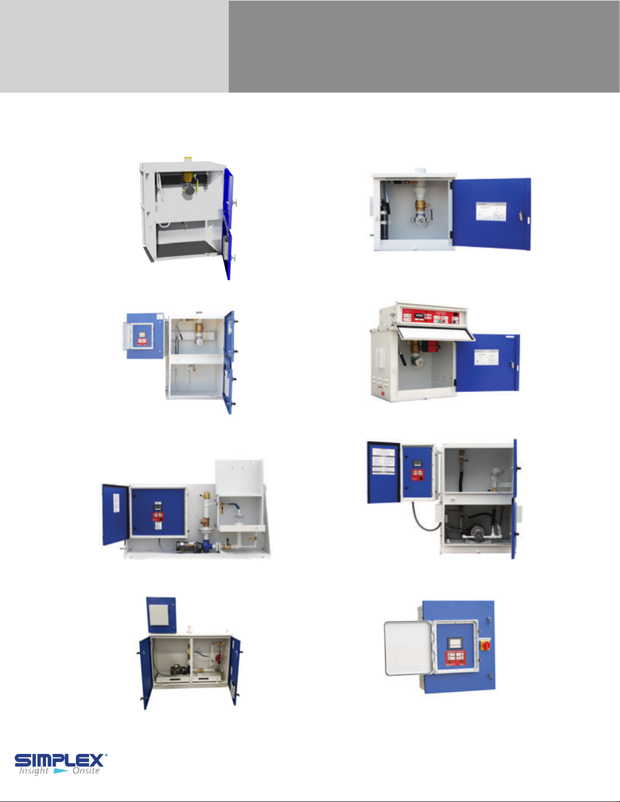
Compact Fuelport
Full-Size Fuelport
Automatic Fuel Port
Smartpump
Compact Automatic Fuelport
Mini-Smartpump
Enclosed Smartpump
Ship Loose Controller
Page 2

TABLE OF CONTENTS
I. Warnings and Cautions
I-A. Safety Information Symbols ................................................................................... 3
I-B. Warnings ................................................................................................................ 3
II. Compact FuelPort / Full-Sized FuelPort
II-A. Installation ............................................................................................................. 4
II-B. Operating Instructions ........................................................................................... 5
III. Compact Automatic FuelPort
III-A. Installation ............................................................................................................ 6
III-B. Setting up the Meter ............................................................................................. 7
III-C. Operating Instructions .......................................................................................... 8
III-D. Maintenance / Troubleshooting ............................................................................ 9
IV. Automatic Fill Controller
IV-A. Installation ........................................................................................................... 10
IV-B. Setting ................................................................................................................. 11
IV-C. Operating Instructions ......................................................................................... 14
IV-
D. Alarms and Warnings .......................................................................................... 15
IV-E. Troubleshooting ................................................................................................... 17
IV-
F. Operating Instructions .......................................................................................... 18
APPENDIX A. PRODUCT WARRANTY ........................................... 19
APPENDIX B. 7 INCH SCREEN REFERENCE ................................ 20
APPENDIX C. SMARTPUMP STARTUP .......................................... 22
Table of Contents - 2
Page 3
I. WARNINGS AND CAUTIONS
I-A Safety Information Symbols
The following images indicate important safety information:
This General warning symbol points out important information that, if not followed, could
endanger personal safety and/or property.
This Explosion warning symbol points out potential explosion hazards.
This Fire warning symbol points out potential fire hazards.
This Electrical warning symbol points out potential electrical shock hazards.
I-B Warnings
• Improper operation of this equipment such as
neglecting its maintenance or being careless can
cause possible injury or death. Permit only
responsible and capable persons to install, operate,
and/or maintain this equipment.
• Potentially lethal voltages and amperages are
present in these machines. Ensure all steps are taken
to render the machine safe before attempting to work
on the equipment.
All hardware covered by this manual have
dangerous electrical voltages and can cause fatal
electrical shock. Avoid contact with bare wires,
terminals, connections, etc., on the hardware, if
applicable. Ensure all appropriate covers, guards,
grounds, and barriers are in place before operating
the equipment. If work must be done around an
operating unit, stand on an insulated dry surface to
reduce shock hazard.
• Do not handle any kind of electrical device while
standing in water, while barefoot, or while hands or
feet are wet. DANGEROUS ELECTRICAL SHOCK
MAY RESULT.
• If trained personnel must stand on metal or
concrete while installing, servicing, adjusting, or
repairing this equipment, place insulative mats over
a dry wooden platform. Work on the equipment
only while standing on such insulative mats.
• Never wear jewelry when working on this
equipment. Jewelry can conduct electricity
resulting in electric shock or may get caught in
moving components causing injury.
• Keep a fire extinguisher near the hardware at all
times. Do NOT use any carbon tetra-chloride type
extinguisher. Its fumes are toxic, and the liquid can
deteriorate wiring insulation. Keep the extinguisher
properly charged and be familiar with its use. If there
are any questions pertaining to fire extinguishers,
please consult the local fire department.
• The National Electrical Code (NEC), Article 250
requires the frame of the equipment to be connected
to an approved earth ground and/or grounding rod.
This grounding will help prevent dangerous electrical
shock that might be caused by a ground fault
condition or by static electricity. Never disconnect the
ground wire.
• Wire gauge sizes of electrical wiring, cables, and
cord sets must be adequate to handle the maximum
electrical current (ampacity) to which they will be
subjected.
• Before installing or servicing this (and related)
equipment, make sure that all power voltage supplies
are completely turned off at their source. Failure to
do so will result in hazardous and possibly fatal
electrical shock.
• In case of accident caused by electric shock,
immediately shut down the source of electrical power.
If this is not possible, attempt to free the victim from the
live conductor. AVOID DIRECT CONTACT WITH THE
VICTIM. Use a nonconducting implement, such as a
dry rope or board, to free the victim from the live
conductor. If the victim is unconscious, apply first aid
and seek immediate medical attention.
• The illustrations in this manual are examples only
and may differ from your unit.
Warnings and Cautions - 3
Page 4
II. COMPACT / FULL SIZED FUELPORT
II-A. INSTALLATION
The FuelPort can be installed in five ways:
1. Welded to a tank (Compact)
2. Attached to a post (Compact)
3. Placed on a stand (Compact)
4. Flush mounted into a wall
5. Bolted to the floor
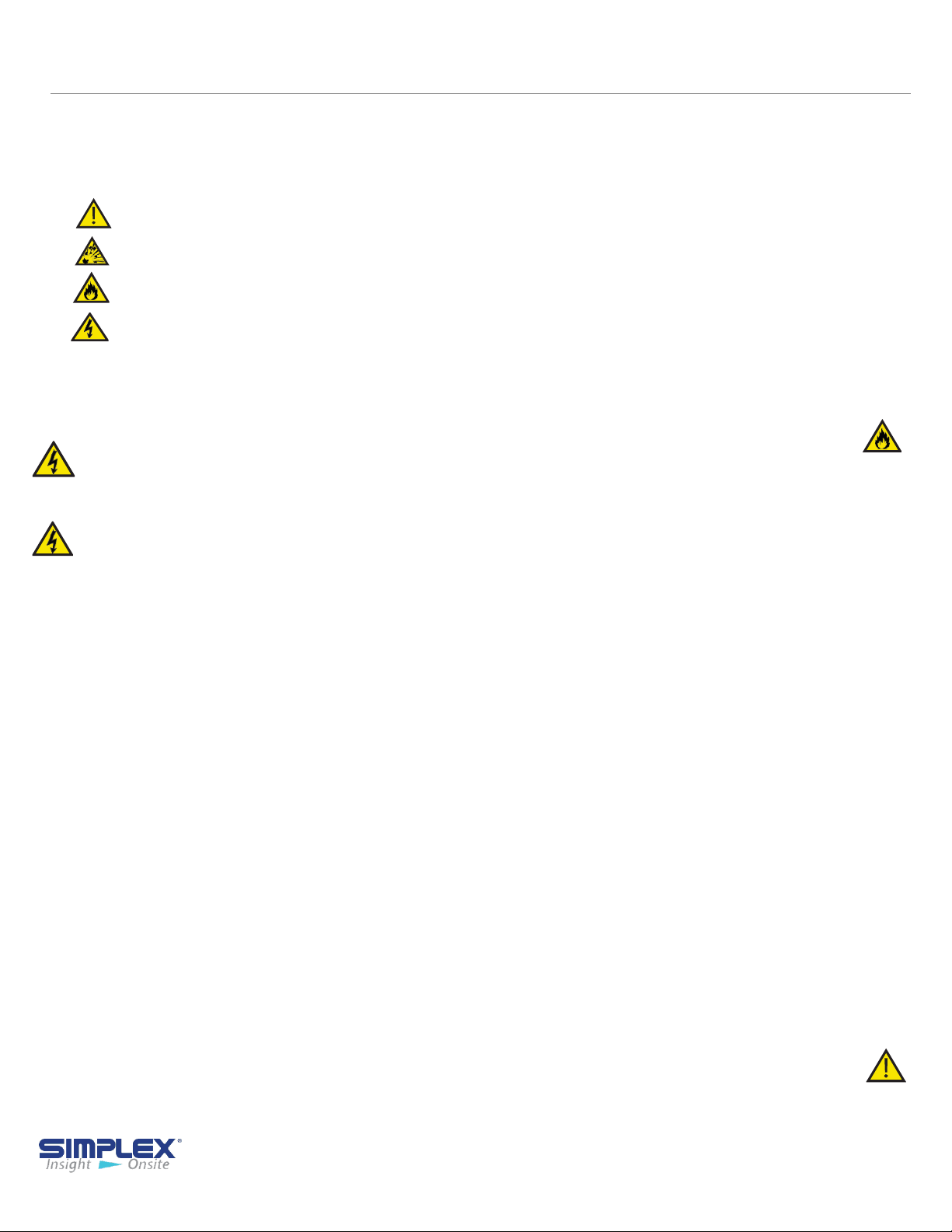
Welding FuelPort to Tank:
You can mount the FuelPort directly on
a storage tank by welding two mounting
brackets to the tank and bolting the
FuelPort to them. (See Weld Brackets
Follow all necessary safety procedures
when welding the brackets to your tank.
Simplex is not responsible for damages
or injuries sustained due to improper
safety precautions.
)
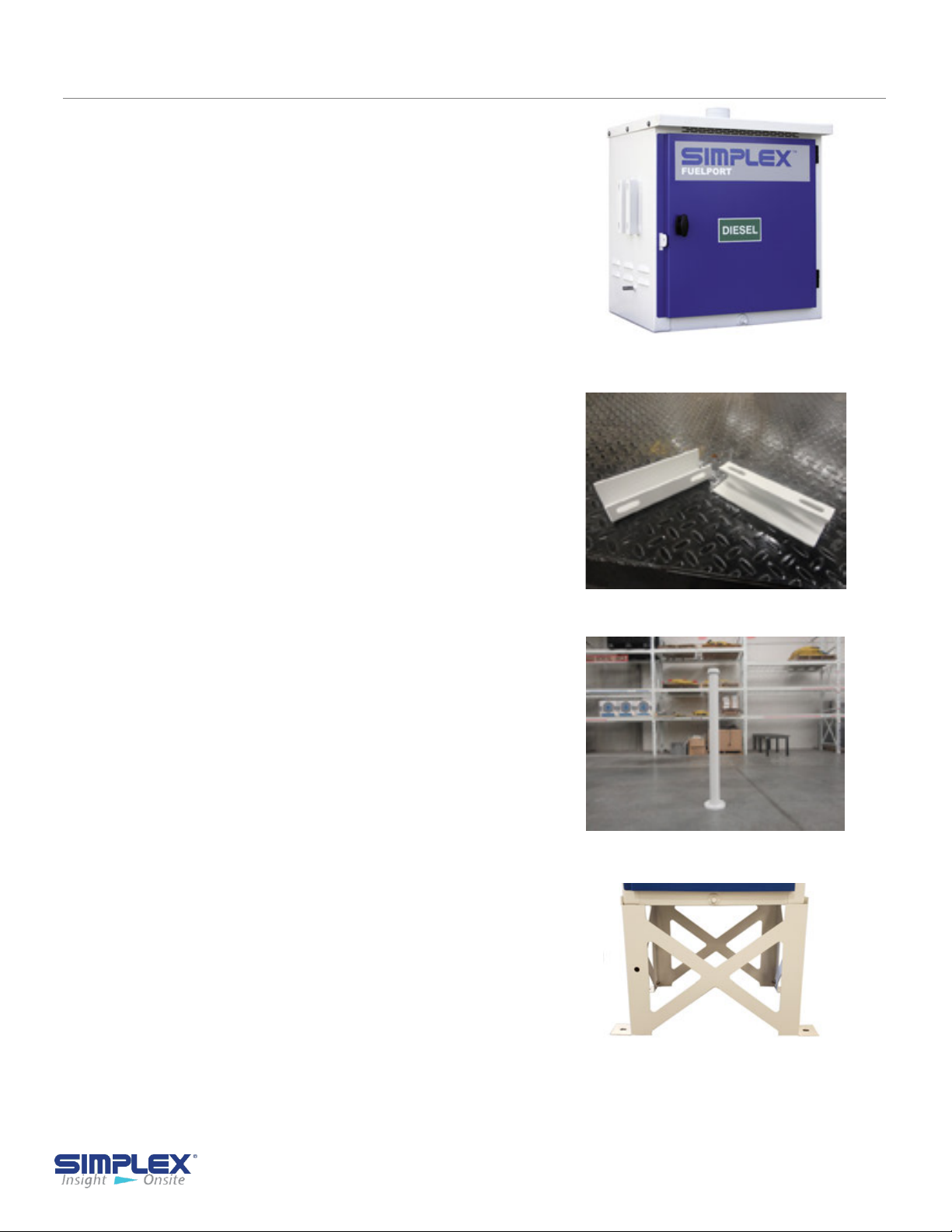
Attaching FuelPort to Post:
With the post mounting option, the
FuelPort can be attached to a freestanding post.
(See Post)
To do so, attach the post to a concrete
pad and use the supplied U-bolt
bracket to attach the FuelPort to it.
post
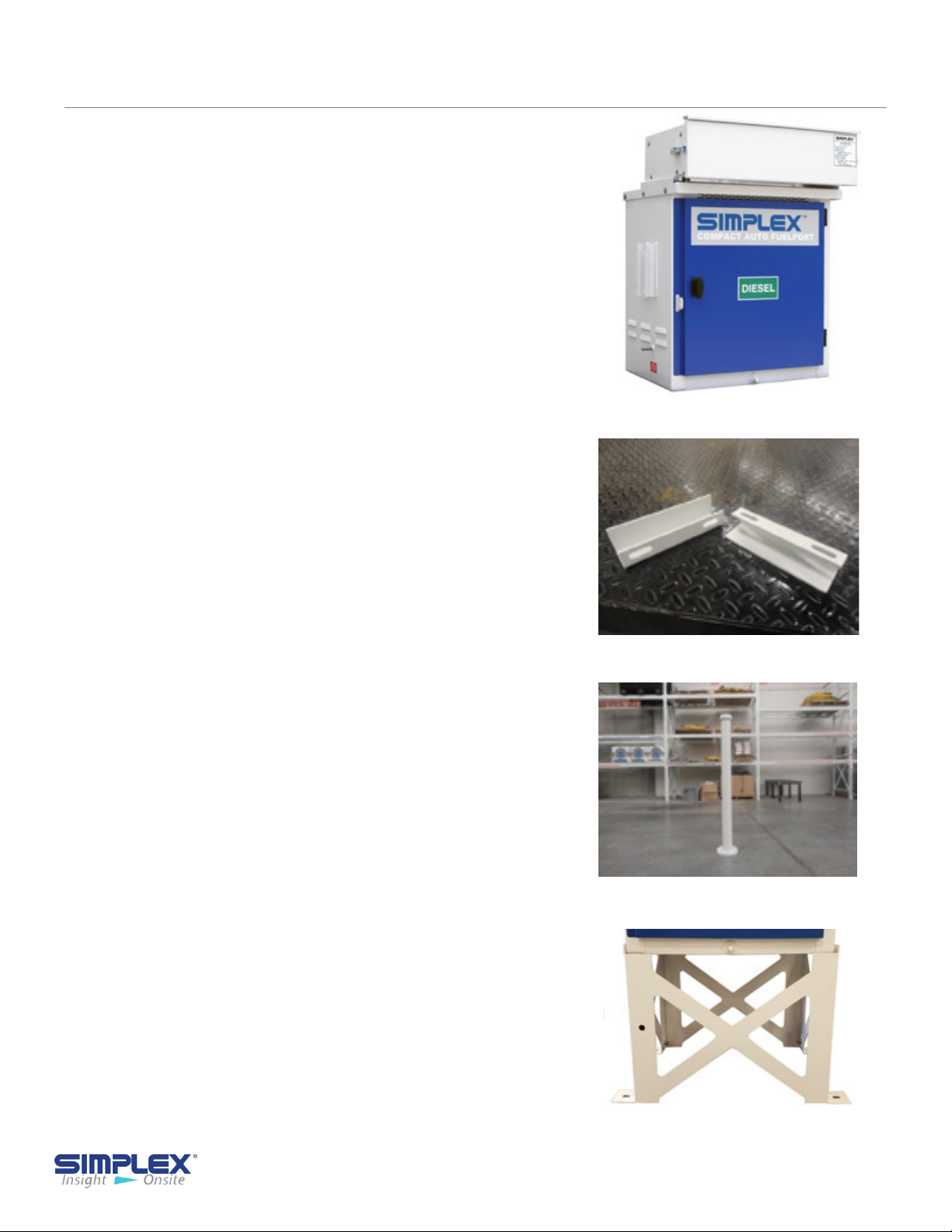
Attaching FuelPort to Stand:
Weld Brackets
Post
Stand
To affix the FuelPort to a stand, simply
attach the stand to a concrete pad using
the pre-drilled holes in the base’s feet,
then affix the FuelPort to the base via
the mounting holes on the front. (See
Stand)
FuelPort Installation - 4
Page 5

Flush Mounting:
To install the FuelPort into a wall, prepare an opening matching the
dimensions of the FuelPort and attach it via the pre drilled mounting
flange. Verify that the wall and mounting hardware are sufficient to
support the FuelPort's weight. Simplex is not responsible for damage
occurring as a result of insufficient support.
Mounting Full-Sized FuelPort to Floor:
The Full-Sized FuelPort can be secured to a wall, a floor or both using
the pre drilled mounting flanges running the height and length of the
cabinet.
Verify that the surface you are mounting the Full-Sized FuelPort to and
the mounting hardware are sufficient to support the FuelPort's weight.
Simplex is not responsible for damages occurring as a result of
insufficient support.
II-B. OPERATING INSTRUCTIONS
1. Connect ground cable
2. Unlock FuelPort and open door
3. Connect delivery hose to hose coupling
4. Open valve on truck and valve in FuelPort
5. Start fill pump
6. Stop fill pump when tank is full or as needed
7. Close truck valve and valve in FuelPort
8. Disconnect delivery hose from hose coupling
9. Close and lock FuelPort door
10. Disconnect ground cable
FuelPort Operating Instructions - 5
Page 6
III. COMPACT AUTOMATIC FUELPORT
III-A. INSTALLATION
The Compact Automatic Fuelport
can be installed in three ways:
1. Welded to a fuel tank
2. Attached to a post
3. Placed in a stand
4. Flush mounted into a wall -
See AFC Controller
Welding FuelPort to Tank:
You can mount the FuelPort directly on a
storage tank by welding two mounting
brackets to the tank and bolting the
FuelPort to them. (See Weld Brackets)
Follow all necessary safety procedures
when welding the brackets to your tank.
Simplex is not responsible for damages or
injuries sustained due to improper safety
precautions.
Weld Brackets
Attaching CAFP to Post:
With the post mounting option, the CAFP
can be attached to a free-standing post.
(See Post)
To do so, attach the post to a concrete pad
and use the supplied U-bolt post brackets
to attach the CAFP to it.
Attaching CAFP to Stand:
To affix the CAFP to a stand, simply attach
the stand to a concrete pad using the pre
drilled holes in the stand’s feet, then affix
the CAFP to the stand via the mounting
holes on the front. (See Stand)
Installing Cable Access:
To bring cabling into the CAFP, remove
one of the six knock outs located along
the right and left vertical sides of the back
of the controller housing and install a 1/2"
3R-rated conduit connector for access.
Post
Stand
Compact Auto FuelPort Installation - 6
Page 7
Installing Control Power:
Please see wiring diagram in the drawing packet
shipped with the unit.
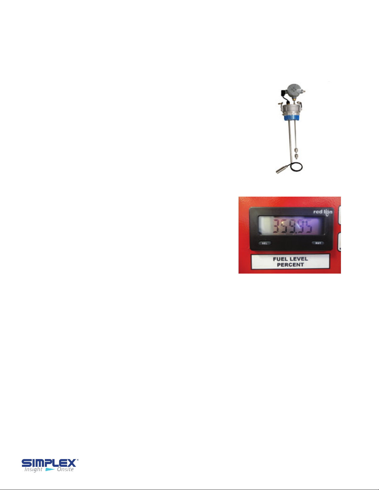
Installing Float Assembly:
To install the float assembly, push the
latch handles on the assembly down and
slide the coupler off.
Apply an appropriate thread-lock to the
threads on the coupler and screw it into
the appropriate tank port.
Slide the assembly into the coupler and
lift the latching arms until the assembly is
locked into place.
Please see wiring diagram in the drawing
packet shipped with the unit.:
III-B. SETTING UP THE METER
Entering the Setup Menu:
There are a number of option for configuring
the meter, but only two concern us: dSP 2,
which allows you to see approximately how
many gallons remain in your tank, rather than
a percentage; and
OFSEt, which calibrates the meter for greater accuracy.
Float Assembly
Meter
To enter the meter's setup menu, press and hold the SEL button for one
second. The screen will begin alternating between Pro and NO. Press RST
while it shows Pro and you will be in the setup menu.
From here, pressing RST will cycle through five options, but all the setting
you will need to change are in the first, 1-INP. Press SEL to enter the
category, and the meter will display rANGE.
Changing the Display From Percentage to Gallons:
When the meter display rANGE, press SEL nine times. The meter should
now read dSP 2. Press RST to change the value, which should initially be
100. Press RST to increase the flashing digit and RST to move one digit
left. Change the value to the maximum capacity of your tank, measure in
gallons. Press and hold SEL to return to the menu, then press SEL
three more times until NO is displayed. The meter should exit the menu
on its own after about a second.
Setting the Meter - 7
Page 8
Calibrating the Meter:
Once the tank is filled to a known quantity of fuel, it may be necessary to
calibrate the meter by changing the meters offset value.
Enter the setup menu as described above. When the meter displays
rANGE, press SEL twice until it displays OFSet. Press RST to change the
setting to the value that will adjust the reading to match the amount of fuel
in your tank. If you need to enter a negative value, press SEL until the leftmost digit is flashing, then press RST
When you have entered a value, press and hold SEL to return to the menu,
then press SEL ten more times until NO is displayed. The meter should
exit the menu on it's own after about a second.
If the meter does not display the correct value, repeat the process to enter
a new offset until the meter is accurate.
until a negative sign appears.
III-C. OPERATING INSTRUCTIONS
If 95% level is
reached,
audible and
visual alarms
are activated.
The Compact
Automatic
Fuel Port
valve closes
completely
and cannot
be reopened
until the level
falls below
95% level.
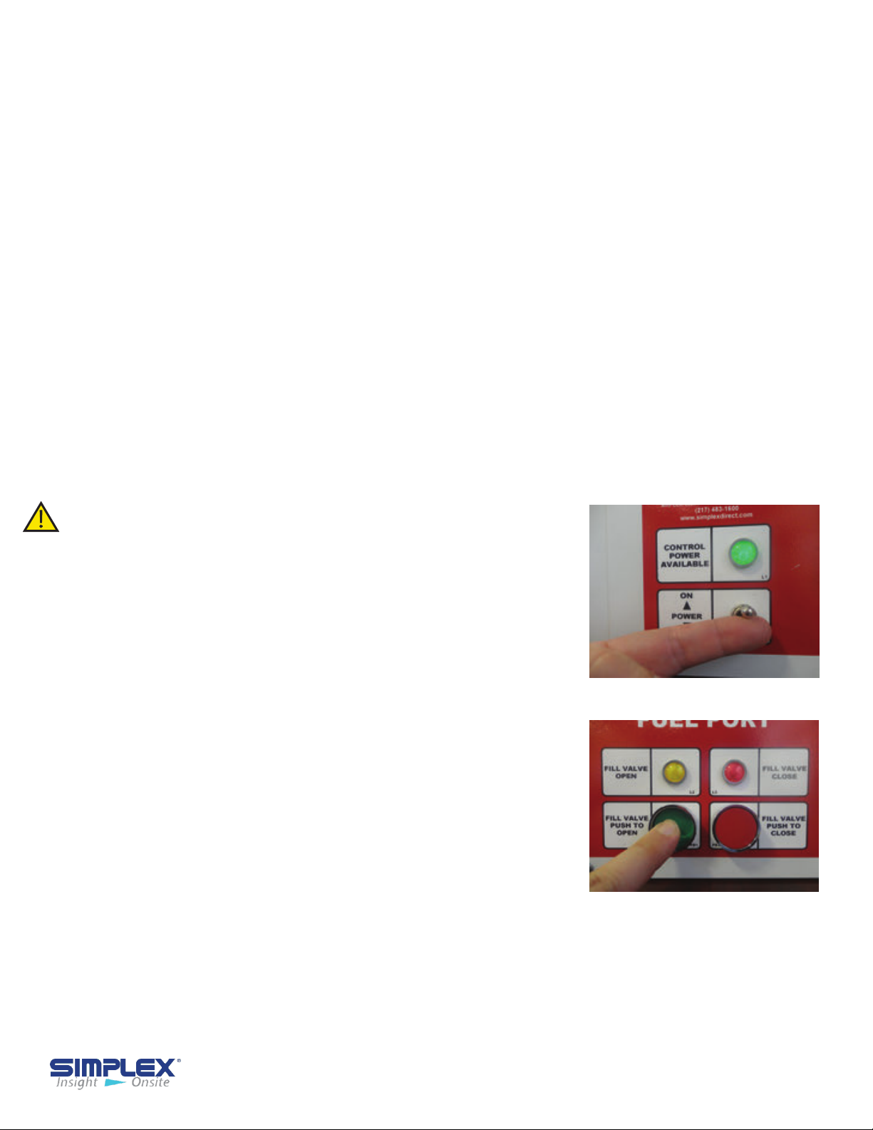
1. Connect the truck ground cable to the stud
provided on the CAFP.
2. Unlock the fill box.
3. Connect the delivery hose to the coupling in the
CAFP.(See Control Power)
4. Open the valve on the truck.
5. Turn the Control Power Switch on and press the
Fill Valve Open pushbutton.(See Open Fill Valve )
6. The valve opens.
7. Start the delivery pump on the truck.
8. Fuel is delivered to the tank.
9. The delivery may be stopped at anytime by
pressing the Close Fill Valve button and proceeding
to step #13.
10. At the 90%(typical) fuel level, audible and visual
alarms are activated and the valve will close partially
to restrict flow.
11. Stop the delivery pump on the truck.
12. Close the valve on the truck.
13. Drain the delivery hose.
14. Disconnect the delivery hose from the CAFP.
15. Turn Control Power off.
16. Close and Lock the Fill Box.
17. Fuel Delivery is completed
18. Disconnect the ground cable from the ground stud.
Control Power
Open Fill Valve
Compact Auto FuelPort Operating Instructions - 8
Page 9

III-D. MAINTENANCE/TROUBLESHOOTING
General Maintenance:
All electrical connections should be tightened every 6
months.
Troubleshooting:
Although the Compact Automatic FuelPorts are
designed with trouble-free operation in mind, some
problem can arise. Please consult the following table
for solutions to the most common issues before
contacting a Simplex service representative.
Problem
Controller
reporting
wrong fuel
level
Remove all
power before
servicing the
CAFP. Never
operate or
service a
CAFP that is
not grounded.
Solution
Verify float assembly is wired correctly.
Verify float assembly is fully installed in tank receptacle. Adjust offset.
If your tank is rectangular, check setting for tank capacity.
Ball valve not
opening and/
or closing
correctly
Controller
not operating
Check FuelPort piping for obstructions.
Checking drawing package to verify valve is wired correctly.
Verify controller is supplied with power. Remove controller cover and
verify relays are seated securely.
Check tightness of electrical connections.
Maintenance and Troubleshooting - 9
Page 10

IV. AUTOMATIC FILL CONTROLLER
The following information applies to the Automatic Fill
Controller (AFC), Automatic FuelPorts, Smartpumps and Mini-
Smartpumps. This does not apply to the 6" Compact Automatic
Controller.
IV-A. INSTALLATION OVERVIEW
The Automatic Fill Controller should be mounted at the filling station, then wired to the
power source, float assemblies, valves, and any other sensors or system integration
connections. Once mounted and properly wired, the AFC panel must be set up/
programmed.
Installing Wiring
The AFC panel must be completely wired prior to applying power. Failure to follow
the wiring information and guide may result in product damage and loss of warranty
coverage. If requested, startup services can be provided by Simplex to check field
wiring prior to applying power, as well as assuring proper operation. See job-specific
wiring diagrams for details.
Installing Cable Access
To bring cabling into the fill controller, pull or drill a hole into the enclosure at a location
of your choosing and install a comparably rated conduit connector for access to the
controller.
Installing Control Power
To install control power, see job-specific wiring diagrams for details.
Installing Motorized Ball Valves
If you have a single-tank system, the ball valve is likely already mechanically and
electrically installed. If you have a multi-tank system, you will have to install the ball
valves in your fuel pipes and connect them to the fill controller.
Verify that the Manual Override Switches on each Motorized Ball Valve (MBV) is set to
“Auto.”
See job specific drawings for valve information.
Installing Pressure Relief Valves
In a multi-tank system, you must install a pressure relief valve between the automatic fill
controller and the MBVs. The PRV is included in your order.
Installing Float Assemblies
To install the float assemblies, push the latch handles on the assembly down and slide
the coupler off. See job specific drawings for float wiring information.
If there are any questions about wiring the AFC, please
contact Simplex directly. Simplex is not responsible for
damage due to incorrect wiring installation.
Compact Fill Controller Installation - 10
Page 11
IV-
B. SETUP
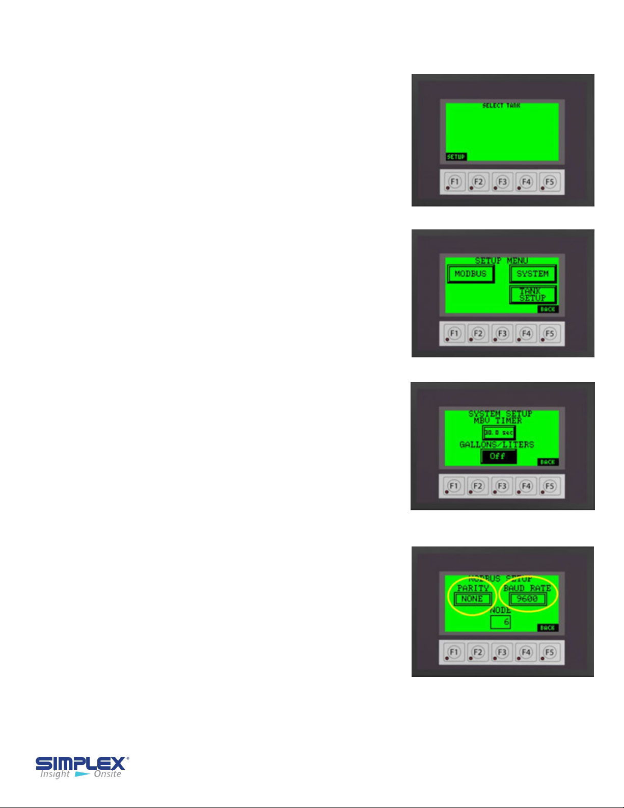
Controller Setup
After the AFC panel has been wired completely
and all connections confirmed, flip the Control
Power switch to ON to apply power
On first power up the touch screen will be mostly
blank as seen on Startup Screen. Below the
screen are 5 function keys used in
conjunction with the information on the screen.
On the Startup Screen, the screen shows
SETUP above the "F1" function key. In this
instance, the "F1" function key would take you to
the setup menu.
From the setup screen you may choose to
configure the MODBUS setting, SYSTEM
settings, or enter the TANK SETUP by pressing
the soft keys on the touch screen. (See Setup
Menu)
Please refer to Appendix B for 7 inch touch screen
examples.
to the panel.
Startup Screen
Setup Menu
System Setup
If MBVs are installed, you may enter the delay
time in seconds for the valve fail timer. You may
also select to display the tank level in either
GALLONS or LITERS. Tank level in percent will
always be displayed regardless if gallons or liters
is selected.
(See System Setup)
Modbus Setup
Each unit is capable of modbus communication via
RS485. You may choose the PARITY, BAUD
RATE, and NODE address for the unit. The
following information is preset from the factory and
may NOT be changed via the touch screen.
PROTOCOL: Modbus
HEX ECHO: 2-Wire
STOP BITS: 1
System Setup
Modbus Settings
Please refer to the Wiring Diagram in the provided
drawing packet for field communication connections.
For TCP/IP or Bacnet communication settings, please see the MODBUS POINTS
LIST in the drawing packet shipped with the unit.
Controller Set Up- 11
Page 12

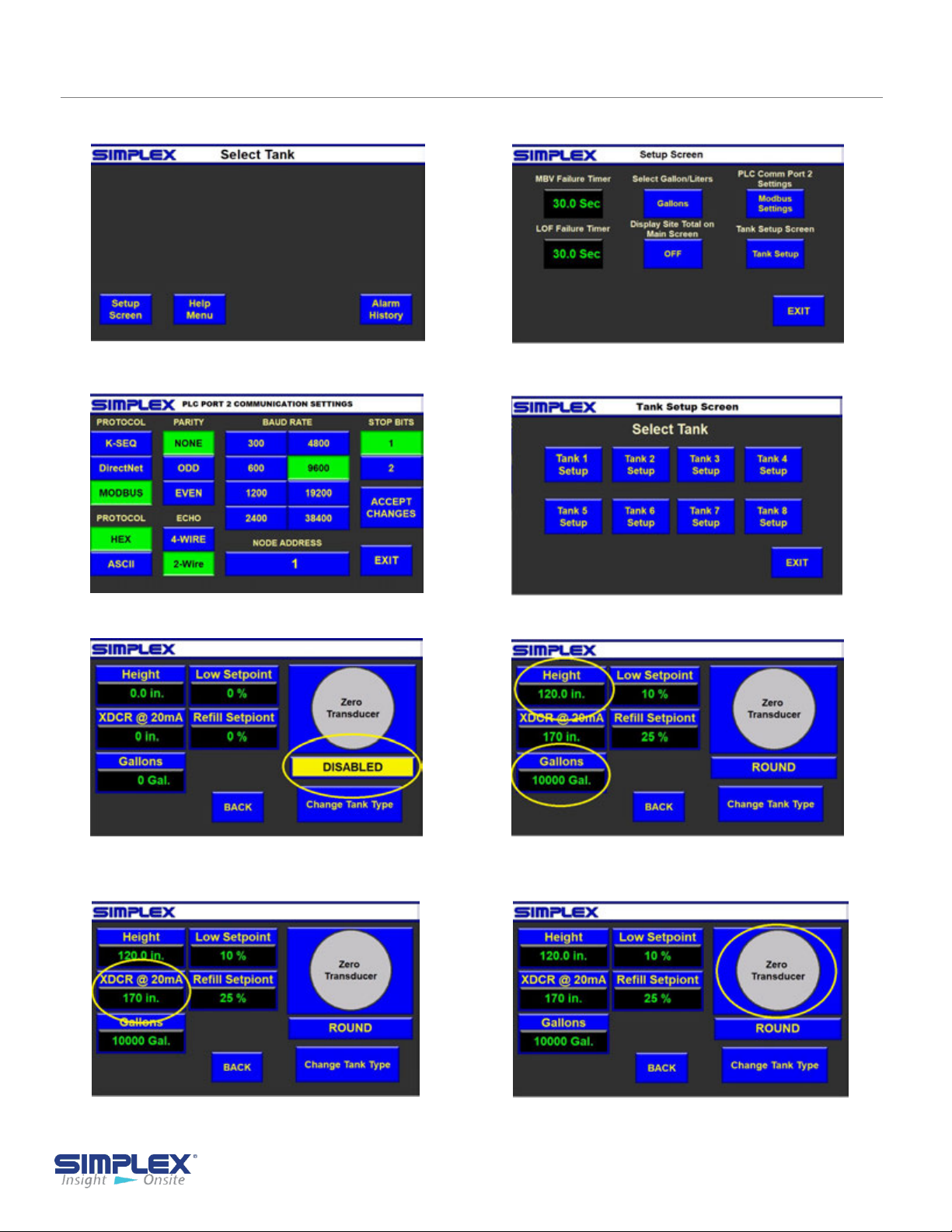
Tank Setup
The controller must be configured for your tanks.
Select tank 1-4 buttons to access each tank setup
screen by pressing the respective tank soft key
button on the touch screen. (See Tank Setup)
To activate the selected tank, press the
"DISABLED" button to select "DISABLED",
"ROUND" or "RECTANGULAR" depending on the
type of tank. (See Tank Type Setup)
Tank Setup
You will now need to enter the tank data used
to calibrate the level transducer. All data will be
entered via a pop up numeric entry key pad
accessed by pressing the data entry field. (See
Tank Transducer )
Next, enter the tank interior depth/height in
inches in the "Height" field. Enter the
maximum tank capacity in gallons in the
"Gallons" field. (See Tank Transducer)
You must also enter the transducer length at 20mA
in inches. For system using a 0-5 PSI pressure
transducer, the length will be 170 In. For systems
using continuous level transducers, you will enter
the "Measuring Range" dimension found on the
"Continuous Level Sensor" drawing of the
provided drawing packet. (See Tank Transducer
2)
Once the tank shape, height and volume have
been set, the level transducer for the tank
must be calibrated (zeroed. To do so, remove
the probe from the tank or hold it above the fluid
level and press and release the "Zero XDCR"
button several times to verify the measurement is
accurate. When finished, install/return the probe
to the tank. (See Zero Transducer)
Tank Type Setup
Tank Transducer 1
Tank Transducer 2
Tank Setup - 12
Page 13

Once the tank shape, height and volume have
been set, the level transducer for the tank
must be calibrated (zeroed. To do so, remove
the probe from the tank or hold it above the fluid
level and press and release the "Zero XDCR"
button several times to verify the measurement
is accurate. When finished, install/return the
probe to the tank. (See Zero Transducer)
Enter the level in percent to trigger a low fuel
alarm by the level probe. This alarm is in addition
to and separate from any low-level floats installed
in the tanks. Entering "0" disables this feature.
(See Low Fuel Set point/Refill Warning)
Enter the level in percent the system should
generate a Refill Reminder Warning. Should a
tank reach this level, a warning will be generated
to inform the site personnel that a fuel delivery
should be scheduled. Entering "0" disables this
feature. (See Low Fuel Set point/Refill
Warning )
Zero Transducer
Low Fuel Set point /
Refill Warning
Repeat the process for each tank in the system.
The main screen will now show the active tank
information. The current percent and
gallons/liters will be displayed for each tank.
(See Main Screen )
System Check
Before filling the tank, check to see if any alarms
or warnings are active. Most alarms and warnings
will clear when resolved, but some require a hard
reset
(toggling the Control Power Off and On) to be
cleared.
All alarms
audible horn and red light on the panel
below the touch screen and by a red back light
on the touch screen. To silence the horn,
push the Silence Horn button on the pop-up
window on the screen or the push button on
the front of the unit. (See Silence Horn)
and warnings are indicated by an
M
ain Screen
Silence Horn
Tank Setup - 13
Page 14

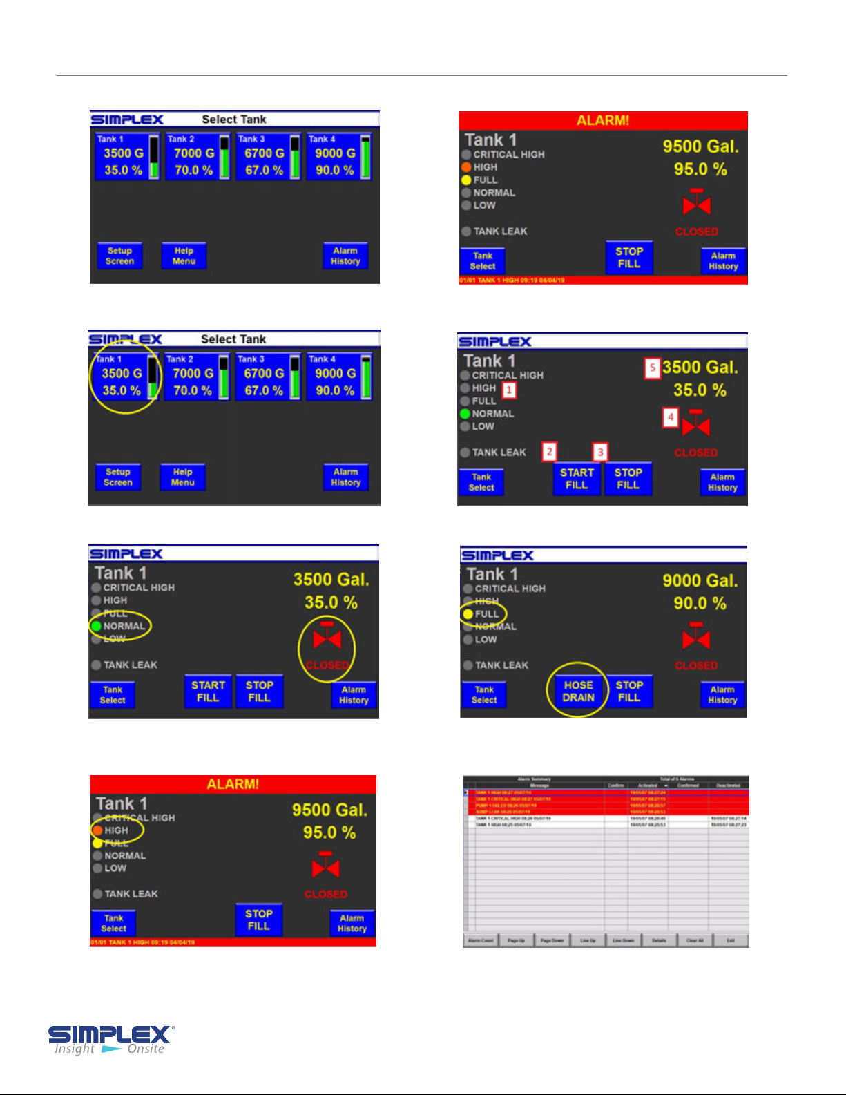
IV-C. OPERATING INSTRUCTIONS
Order of Operation
To fill a tank in the system, you must place the
"
Control Power" switch below the screen in the
ON position. This will allow certain option to
appear on the screen and powers the motorized
ball valves.
Select the appropriate tank by pressing the level
indicator for the required tank. This will take you
to the individual tank detail screen (See
Select
On this screen you will find the current tank status
and fill controls.
1. Current tank status
2. Start Fill HMI soft key
3. Stop Fill HMI soft key
4. Tank valve status
the on-board pump status will be displayed here
as well.
5. Current tank level in percent and gallons/liters
6. Start Fill Function Key F1
7. Stop Fill
(See Tank Detail Screen
.
)
Function Key F2
. If used with a Smart Pump,
).
Tank
Tank Select
Tank Detail Screen
NOTE: Function keys are not used with the
7 inch touch screen option.
On the selected tank detail screen, you will see that
the tank status is normal and the valve is "Closed"
(Start Fill).
To start the fill process, first connect the truck
ground cable to the ground stud. Unlock the fill box
and connect the truck hose to the hose coupling. If
used with a Smart Pump, open the valve on the
truck at this time. Press the "Start Fill
F1. The fill valve will open for the selected tank.
The valve status will change from "Closed" to
"Travel" to "Opened". If used used with a Smart
Pump
" button or
Start Fill
Operating Instructions - 14
Page 15
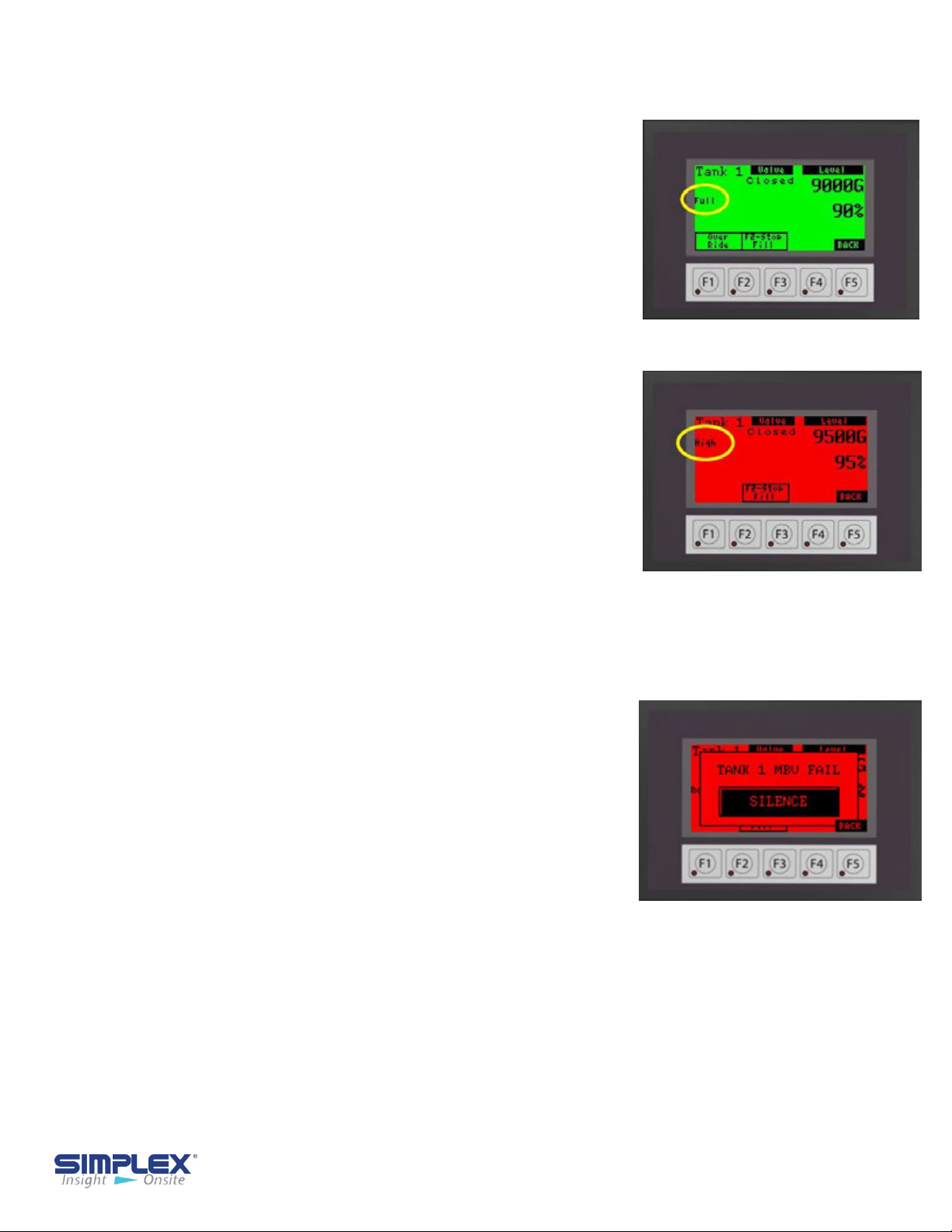
The delivery may be stopped at any time by
pressing the "Stop Fill" button or F2.
As the tank fills, the level is continuously updated. If
you wish to stop filling before the tank reaches
"Full" (90% typical), stop the truck delivery pump,
and press "Stop Fill" (or F2).
Once the tank reaches the "Full" level (See Tank
Full), the alarm horn will sound to alert the driver
and the tank valve will close. The fill process may be
started again for 30-second intervals by pressing the
"Fill Start/Override" again to drain the delivery hose,
if required. If the selected Tank reaches the
"High" (95% typical) level, the alarm will sound, the
valve will close, and all filling operations for the
selected tank will be prohibited (See Tank High).
Another tank may be selected for fill, if applicable.
Repeat the fill process for all tanks in the system.
Once filling is completed, close any manual valves,
remove the delivery hose, and replace the fill cap.
Remove the ground cable and turn the control power
off.
Tank Full
Tank High
IV-D. ALARMS AND WARNINGS
Alarms
The AFC has several states which cause alarms.
Alarms are indicated by
panel below the touch screen, an audible horn and
indicators on the touch screen. The horn may be
silenced by pressing the pop up "Silence" button. The
specific alarm will be displayed above the silence
button.
(See Alarm)
Tank specific alarms are also displayed on the
applicable tank detail screen.
On 7 inch screen (optional upgrade) the alarms maybe
viewed by pressing the "Alarm History" button on the
Main Screen. (See Appendix B)
a red light on the main
Alarm
Alarms and Warnings - 15
Page 16

Actions and Components are Job Specific
See Drawing Package for Details
Alarm
Low Fuel
Refill Warning
Full level
High
Critical High
Triggered By
Level Transducer
Level Transducer
Float Switch
Float Switch
Float Switch
or
Level Transducer
Action Taken By AFC
Audio/Visual Alarm Only
Audio/Visual Warning Only
90% (typical) tank level Typical
Audio/Visual Alarm
Closes valve for selected tank
Stop on-board Pump
95% (typical) tank level Audio/
Visual Alarm
Closes valve for selected tank
Stops on-board pump
Prohibits fill of selected tank
98% (typical) tank level typical
Audio/Visual Alarm
Closes valve for selected tank
Stops on-board pump
Prohibits fill of all tank
Tank Leak
Loss of Flow
MBV Failure
Overload
Float Switch
Flow Sensor
Loss of signal from the
valve or incorrect
position signal from
valve
Motor Starter
tripped
Audio/Visual Warning Closes
all valves
Stops on-board pump
Prohibits fill of selected tank
Audio/Visual Alarm
Closes all valves
Stops on-board pump
Prohibits fill of all tanks
Audio/Visual Alarm
Closes all valves
Stops on-board pump
Prohibits fill of all tanks
Audio/Visual Alarm
Closes all valves
Stops on-board pump
Prohibits fill of all tanks
Alarms and Warnings - 16
Page 17

IV-E. TROUBLESHOOTING
Problem
Screen is blank
Tank level
indication reads
"0%" and "0 Gal"
Tank indicates
"Full", "High" and
"Critical High"
Cause
1. Control Power isn't
available
2. The fuses are blown
1. Level transducer not
calibrated properly
2. The level transducer
is disconnected.
3. The tank wiring has
not been properly
connected
4. The tank is empty.
1. The float stem has
been disconnected.
2. The float stem is not
receiving power.
Solution
1. Verify the control power switch
is in the ON position. If so,
contact the facilities manager for
power issues
2. Replace the fuses
1. Recalibrate the level
transducer.
2. Reconnect the level transducer.
3. Check all tank field wiring.
4. Schedule a fuel delivery
1. Reconnect float stem.
2 . Check float stem wiring.
Tank indicates a
valve failure
3. The fuses are blown.
4. The tank is at a
critical high state.
1. Fuses are blown.
2. Valve mode selector
switch is not in AUTO
3. The valve wiring was
wired incorrectly.
3. Replace fuses.
4. Cease filling operations.
1. Replace fuses.
2. Place selector switch in AUTO
3. Check all valve field wiring.
Troubleshooting - 17
Page 18

IV-F. OPERATING INSTRUCTIONS - AFC Controller
These are abstracted instructions. Please refer
to your fill controller section for details.
1. Connect a truck ground cable from the truck to the provided ground stud.
2. Connect the delivery hose from the truck to the hose coupling at the unit.
3. On Smartpump/Mini-Smartpump units, open both inlet/outlet isolation valves.
3-a. On multi-tank Fuelports, verify the manual ball valve is open.
3-b. Smartpump ONLY, open air purge valve until air has been purged from system and then
close valve.
4. Turn the Fill Controller power switch to the ON position.
5. Select the appropriate tank to be filled on the touch screen.
6. If equipped with a Bypass feature, verify the switch is in the proper position. Use "By-pass" for
trucks equipped WITH a pump or "On-Board" for trucks WITHOUT a pump.
7. Open valve on truck.
8. Press "Start Fill" button on the touch screen or F1 if applicable.
9. Wait for fill valve to completely open, if applicable.
10. On Smartpump/Mini-Smartpump units, the on-board pump will start automatically.
10a. FuelPort units, start the truck pump
11. Delivery may be stopped at any time by pressing the "Stop Fill" button on the touch screen or F2
if applicable.
12. When the "Tank Full" level is reached, an indication will be displayed, the alarm horn will sound,
the fill valve will close, and/or the on-board pump will stop, if applicable.
13. Filling may continue in 30 second increments by pressing the "Hose Drain" button, or F1 if
applicable.
14. Stop the pump on the truck, if applicable.
15. If filling more than 1 tank, return to step 5.
16. If the "Tank High" level is reached, an indication will be displayed, the horn will sound, the valve
will close, and/or the on-board pump will stop, if applicable. The selected tank will be locked out
from any further filling operation until the level drops below the high level.
17. If any tank in the system should reach the "Critical High" level, all valves and any pumps will be
locked out until the critical high has cleared. (Multi-tank system only)
18. When filling operations are complete, return to the Main Screen.
19. On Smartpump/Mini-Smartpump units, close both inlet/outlet isolation valves.
20. Disconnect the delivery hose.
21. Turn the Fill Controller power switch to the OFF position.
22. Close and lock the fill unit.
23. Disconnect the truck ground cable.
Operating Instructions - 18
Page 19

APPENDIX A - PRODUCT WARRANTY
SIMPLEX, Inc., warrants the industrial electrical control, test and accessory equipment and parts and
accessories thereof to be the kind and quality described in SIMPLEX’s specifications and to be free
from defects in material or workmanship under normal service, its obligations under this warranty
being limited to repairing or replacing, at its option, any part or parts which shall, within twelve (12)
months from date of shipment from its factory, as indicated by serial date code on the nameplate or
sales records, be returned to SIMPLEX or an authorized SIMPLEX repair station, with transportation
costs prepaid, and which its examination shall disclose to its satisfaction to have been thus defective.
The provisions of this warranty shall not apply to any equipment, part or accessory which
(a) has been improperly specified by buyer;
(b) has been improperly stored or handled prior to placing in service;
(c) has been improperly mounted or connected;
(d) has not been operated within specifications stated on its nameplate, label or placard;
(e) has not been properly maintained;
(f) parts supplied by buyer for inclusion in finished equipment are not covered by this warranty;
(g) components or assemblies specified by buyer with no substitution permissible that are not normally
used by SIMPLEX.
SIMPLEX reserves the right to reject warranty claims of any kind against assembled equipment, parts or
material for which SIMPLEX has not received payment in full.
Should buyer, at his own risk, elect to replace defective equipment or parts in the field rather than
return equipment to SIMPLEX’s factory or authorized repair station, SIMPLEX will supply and invoice
parts at normal prices upon receipt of buyer’s bona-fide purchase order. Defective equipment or parts
returned for in-warranty crediting in exchange for replacement parts must be returned within 45 days
from date of shipment of replacement in order to qualify for warranty consideration. Defective
equipment or parts returned after 45 days may be subject to a restocking charge of 20% or a minimum
charge of $50.00, whichever is greater.
This warranty is in lieu of all other warranties, express or implied, and all other obligations or liabilities
on the part of SIMPLEX, and SIMPLEX neither assumes nor authorizes any other person to assume for
it any other liability in connection with any such electrical control, test or accessory equipment or
accessories.
Product Warranty- 19
Page 20
APPENDIX B - 7 INCH SCREEN REFERENCE
Startup Screen
Modbus Settings
Setup
Tank Setup
Tank Type
Tank Transducer 2
Tank Transducer 1
Zero Transducer
7 Inch Screen Reference- 20
Page 21
APPENDIX B - 7 INCH SCREEN REFERENCE
Main Screen
Tank Select
Silence Horn
Tank Detail Screen
Start Fill
Tank High
Tank Full
Alarm
7 Inch Screen Reference - 21
Page 22

APPENDIX C - SMARTPUMP STARTUP
CHECKING PUMP ROTATION
1. Turn off the control power circuit breaker.
2. Remove the shaft coupler guard
urn on the control power circuit breaker.
3. T
4. Press the Start Fill button. The pump should start and run.
5. The shaft should rotate in the direction indicated on the sticker
on the motor (See Rotation Sticker).
(if present) from the pump (see
Rotation Sticker).
6. If rotation is incorrect:
a. Press the Stop Fill
button.
b. Turn off the control
power circuit breaker.
c.
Open
the Control Panel
door to access the
control compartment.
Locate the overload relay
d.
(See Overload Relay)
e.
On either side of the
relay, reverse the
black and red wires:
connect the red wire
to line one and the
black wire to line two.
f. Clos
e the Control
Pane door and repeat steps
3 through 5.
Rotation Sticker
Overload Relay
7. Turn the control power circuit breaker off.
8. Reinstall the shaft guard.
9. Connect the
storage tank(s) using 3-inch steel or black iron
pipe.
outlet of the SmartPump to the
SmartPump Startup - 22
Page 23

APPENDIX C - SMARTPUMP STARTUP
DRAINING THE SPILL CONTAINMENT BASIN
1. Start
2. The
3. Stop the pump when the basin is
the pump by pressing the
Start Fill button.
pump
the spill basin. A full basin
should take about 20 seconds to
empty.
empty by pressing the Stop Fill
button.
will start and empty
PURGING THE PUMP
You must purge the pump of air on
initial startup or whenever as has
entered the pump system.
1. Open the Smartpump inlet and
outlet valve to flood the system.
(See Pump Inlet Valve
Outlet Valve
)
and
Pump Inlet Valve
Pump Outlet Valve
Pump
2. Open the air purge valve located at
the pump discharge, then close valve.
(See Air Purge Valve)
The pump should now be purged of
air.
Air Purge Valve
SmartPump Startup - 23
Page 24

for all your Load Bank and Fuel Supply needs.
Simplex, Inc.
5300 Rising Moon Road
Springfield, IL 62711
800-637-8603
www.simplexdirect.com
This manual and all of its contents Copyright © 2019 Simplex, Inc.
All Rights Reserved
24
 Loading...