

Page 1

Film-Tech
The information contained in this Adobe Acrobat pdf
file is provided at your own risk and good judgment.
These manuals are designed to facilitate the
exchange of information related to cinema
projection and film handling, with no warranties nor
obligations from the authors, for qualified field
service engineers.
If you are not a qualified technician, please make no
adjustments to anything you may read about in these
Adobe manual downloads.
www.film-tech.com
Page 2
35mm UNITIZED PROJECTOR
STRONG
INTERNATIONAL
a division of Ballantyne of Omaha, Inc.
4350 McKinley Street
Omaha, Nebraska 68112 USA
Tel 402/453-4444 • Fax 402/453-7238
www.strong-cinema.com
INSTRUCTION MANUAL
and PARTS LIST
Page 3

SA VE THESE INSTRUCTIONS
This equipment is intended
FOR PROFESSIONAL USE ONLY
Read and understand all instructions before using
WARNING
To avoid risk of fire, do not use
nitrate or other flammable film.
Use safety film only.
EXERCISE CAUTION WHEN
WORKING AROUND MOVING
PARTS
Page 4

TABLE OF CONTENTS
PREFACE 1
FIGURE 1 3
FIGURE 2 4
INSTALLATION
Unpacking 5
Mounting 5
Lamphouse Alignment 6
Lamphouse Light Shield 6
Picture Changeover 6
Lens Turret 6
Projection Lenses 7
Flywheel 7
Sound Reader Assembly 8
Analog 9
Digital 10
START-UP PROCEDURES
Initial Oiling 15
Threading 16
Initial Operation 17
MAINTENANCE
Lubrication 18
Sprockets 18
Pad Rollers 18
Fastening Hardware 18
Film Gate 18
Film Trap 18
Lens Turret 19
Overall Appearance 19
i
Page 5

TABLE OF CONTENTS (continued)
FIGURE 3 20
FIGURE 4 21
ADJUSTMENTS & REPLACEMENTS
Intermittent Shoe Replacement 22
Film Trap & Aperture Changer 22
Pressure Strap Replacement 22
Studio Guide Replacement 22
Aperture Plate Adjustment 22
Gear Compartment Cover 23
Intermittent Movement 23
Intermittent Sprocket 24
Framing Light 24
Pad Roller Assemblies 24
Shutter Timing 25
Shutter Replacement 25
Film Gate Replacement 25
Film Sprocket Replacement 26
Sprocket Gear Replacement 26
Automatic Lens Turret 26
PARTS LISTS 28
STRONG INTERNATIONAL
a division of Ballantyne of Omaha, Inc.
Engineering/Sales
July 1, 2004
ii
Page 6

PREFACE
THE SIMPLEX APOGEE PROJECT OR, combining rugged construction with ease of operation, provides theatre owners with a superior mechanism, engineered to the high standards set for all Strong
International products. The following design features illustrate why the Simplex Apogee Projector is able
to provide continuously excellent performance throughout its long operating life:
UNIT DESIGN
Unit method of design simplifies part replacement and maintenance. All units may be quickly
removed and replaced. Components within a particular unit are just as easily handled.
SOUND READER
The analog and digital sound reader components are mounted to the same main frame as the optical
elements, insuring a straight film path. Minimal flutter and “wow” comply with all SMPTE standards.
MAIN DRIVE
The projector main drive is connected directly to the drive motor without pulleys and belts, eliminating the
need to adjust tension and/or replace these components.
OPTICS
A conical shutter, positioned close to the picture aperture, provides very high light efficiency. Optical
design is compatible to modern xenon lamphouse systems.
LENS TURRET
The Apogee Lens Turret is available in either Automatic or Manual configurations. The standard
turret accommodates (1) each 2-25/32" (71mm) diameter Wide Screen (flat) and Anamorphic (CinemaScope)
lens without use of a MagnaCom. A three-lens turret is available for export applications. Individual focus
controls permit concise focusing of each lens independently .
FILM COMPARTMENT
The roomy film compartment permits ease of threading and cleaning. The lens turret is hinged and
swings open for added convenience.
GEAR COMPARTMENT
The gear compartment has a removable cover, rounded corners, and an enameled finish which simplifies
cleaning and service.
1
Page 7

MAIN FRAME
The main frame casting forms a single unit that is noteworthy for its simplicity and strength. A single
thread path serves all film-handling elements for both precise projection and sound reproduction.
FILM SPROCKETS
The upper feed and lower holdback sprockets, having twenty-four teeth each, reduce shaft speeds to
prolong operating life, permit smoother wraparound, and lessen the danger of splice breakage. Exclusive use
of VKF
®
sprockets insures minimum film wear. The pad rollers are made of durable, lightweight nylon.
FILM TRAP
The film trap conforms to the curved film gate, and accommodates the multiple-aperture plate used
with the lens turret. Film tension can be easily adjusted while the machine is running. The trap is readily
removed and replaced for routine cleaning and maintenance.
FILM GATE
The curved gate, together with the film trap, controls the movement of the film past the aperture. Gate
curvature provides compensation for heat-induced warping of the film at the aperture, thus insuring a sharper
image on the screen. The film gate runner is easily removed, cleaned, and replaced.
INTERMITTENT MOVEMENT
The intermittent movement features a webbed starwheel for high strength, long life, and positive
registration. The VKF
®
intermittent sprocket is adjustable, making absolute alignment possible.
LUBRICATION
A Spray-O-Matic Lubrication System, with a gear-driven oil pump, completely lubricates all moving
components. The moving parts inside the gear compartment are visible through the full-vision, oil-sealed
plexiglass window on the off-operator side of the mechanism. The intermittent movement lubricates itself by
pump action, and the Spray-O-Matic system. An oil level sight glass in the film compartment permits a visual
check of the oil level.
COOLING
The Simplex Apogee Projector includes a heat sink positioned behind the shutter blade and aperture to
absorb radiant heat and protect the trap and film. Cooling fans further reduce heat at the film plane.
®
VKF
is a registered trademark of LaVezzi Precision, Inc. Elmhurst, Illinois
2
Page 8

FOCUS
KNOB
FILM TRAP
COOLING FANS
SHUTTER ADJUSTING
KNOB
PICTURE
CHANGEOVER
DEVICE
TURRET “OPEN”
LEVER
CONTROL
CABINET
OIL FILL
CUP
DEADSTOP
ADJUST
DRIVE
MOTOR
FOCUS
KNOB
RESET LEVER, INDEX
STOP PIN
FIGURE 1
3
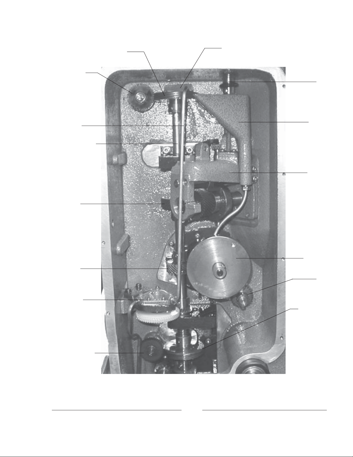
Page 9

FILM TENSION
ADJUSTING
KNOB
CHANGEOVER
DEVICE
FRAMING
LIGHT
GATE
RELEASE
PIN
UPPER FEED
SPROCKET
SHUTTER
GUARD
RELEASE,
APERTURE
MOTOR
COVER
FRAMING
HANDLE
APERTURE
CUE
ANALOG
SOUND
READER
DIGITAL
SOUND
READER
FIGURE 2
INTERMITTENT
SPROCKET
HOLDBACK
SPROCKET
OIL SIGHT
GLASS
OIL DRAIN
4
TURRET
RESET
SWITCH
APERTURE LOGIC
SENSING SWITCH
Page 10

INSTALLATION
EACH SIMPLEX APOGEE PROJECTOR is carefully inspected and film-tested before
leaving the factory. Carefully inspect the unit on receipt for any shipping damage, and file any damage
claims with the carrier immediately. It is the responsibility of the consignee, not Strong International or its
dealers, to file such claims.
THE FOLLOWING RECOMMENDATIONS should be studied carefully prior to installation. Even if received mounted and prewired to a Strong console, it is advisable to review and inspect the
following steps prior to energizing the system. Your Strong International Dealership may wish to assist in
installing those projection booth products supplied by their firm.
UNPACKING
The Simplex Apogee projector is shipped in a sturdy wooden crate. TOP and OPEN THIS SIDE are
marked on the carton. The projector is mounted to the base of the crate with (2) 5/16-18 hex head screws.
An accessory kit is shipped with each Simplex Apogee projector. The kit includes the following:
(1) Can Simplex Projector Oil
(1) Oiler
(1) Set Allen Wrenches
The tools and accessories are required for adjustments and routine maintenance after installation. Store
them in a secure location in the projection booth.
MOUNTING
Mount the Apogee to the mounting arm on the front of the console or pedestal. Some consoles will
require spacer block(s) to position the projector’s picture aperture at the correct working distance; see the
console installation instructions. Start the top two bolts, through the washers and spacer block (if required),
into the back of the main frame casting. The projector can then be lifted into place, and the top two bolts into
the casting lowered into the slotted holes in the projector mounting arm. In this manner, the mounting arm
will bear the weight of the projector while the two bottom bolts are started.
T o avoid crossthreading, the 3/8-16 mounting bolts should be screwed in fingertight as far as possible.
Before tightening the bolts, check that both the lamphouse/console and projector are on the same, level plane.
T erminals for the drive motor power leads are provided in the projector control cabinet. See the following
section detailing Electrical Connections.
5
Page 11

LAMPHOUSE OPTICAL ALIGNMENT
Carefully follow the lamphouse manufacturer’s instructions regarding correct optical alignment
between the lamphouse and projector. The lamphouse is generally aligned to the projector aperture, but
some consoles require positioning the projector to the optical center of the lamphouse. Never operate the
lamphouse with the douser open unless the projector is running.
LAMPHOUSE LIGHT SHIELD
Light shields, or nose cones, supplied by the lamphouse manufacturer, may be installed between the
projector shutter guard and the lamphouse snood. Make certain that the nose cone does not obstruct the rotation
of the shutter. T rim or otherwise modify the nose cone as required.
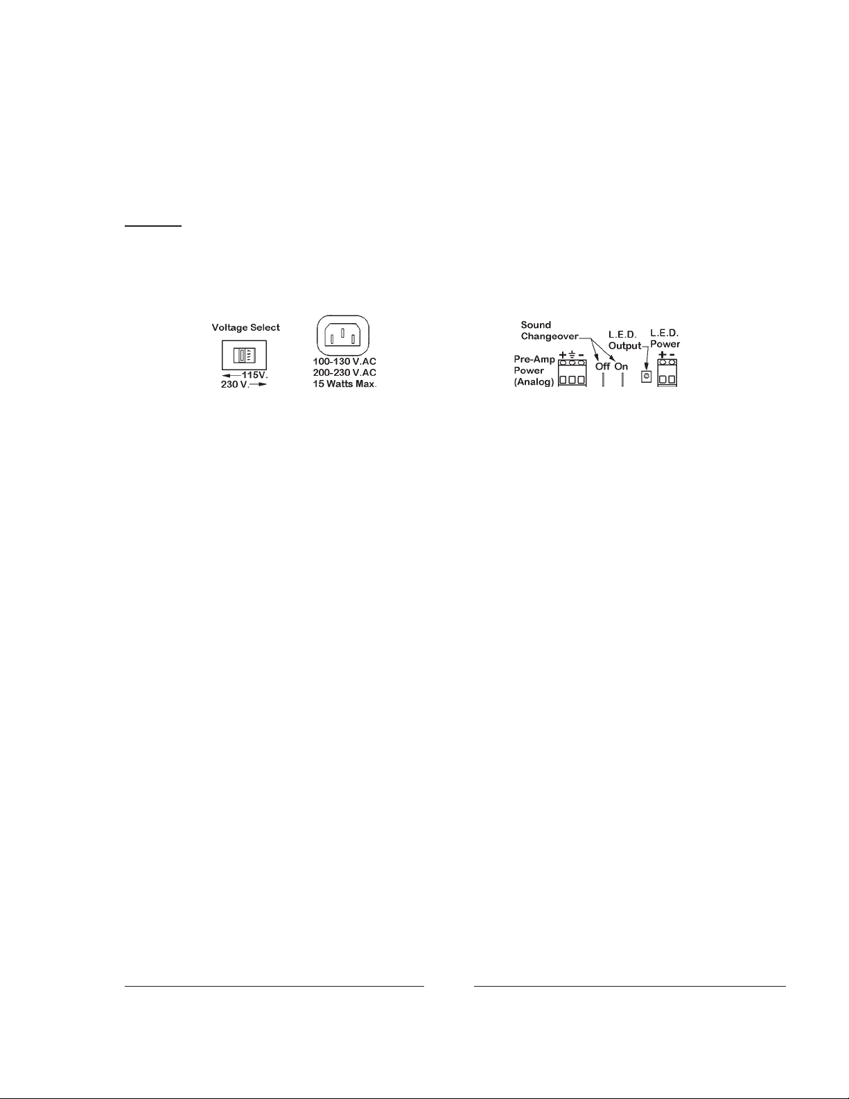
ELECTRICAL CONNECTIONS
All electrical connections to the Apogee terminate in the cabinet mounted on the side of the projector
adjacent to the gear compartment. Loosen the quarter-turn fastener and open the door to access the terminals.
Input voltage is user-selectable by connecting the transformer plug
to one of the two receptacles located on the top of the “Power” printed
circuit board. Connect the plug to J7 for 110 volt operation, or to J8 for
220 volt. After selecting the voltage, apply AC phase and neutral to the
two uppermost terminals on the right barrier strip. This AC input
powers the turret controller, the turret and aperture motors, and the L.E.D.
framing light. An earth ground must be connected to the ground lug at
the lower right corner of the cabinet.
The lower five terminals of the right barrier strip allow power
connections from the automation controller to the picture changeover
and the projector drive motor. The lower five terminals of the left
barrier strip provide connection points to the devices. Voltage to these
devices is generally supplied by, or switched through, the automation
controller. All NEUTRAL connections are common.
Turret inputs connect to the (4) marked terminals on the lower
part of the turret control PCB mounted to the cabinet door.
Picture Changeover
The Apogee is normally shipped with a Strong International
115 V.AC (52-60325) or 230 V.AC (52-60326) picture changeover de-
vice. If ordered separately, connect the changeover leads as follows:
Blk - OPEN Wht - COMMON
Red - CLOSE Grn - GROUND
NOTE: These changeover devices require an AC pulse to operate.
Connecting the changeover device to a sustained AC circuit will destroy
the electrical coil(s). Check carefully the instructions supplied with the
automation controller and/or the (installer-supplied) switching circuit.
6
Page 12

Lens Turret
The MANUAL lens turret requires no electrical connections. Installer connections to the AUTO-
MA TIC turret are made to the J4 terminals located on the printed circuit board on the control box door adjacent
to the gear compartment cover on the side of the projector. The inputs (FEED, SPECIAL, FLA T , and SCOPE)
are derived from an automation controller and/or other installer-supplied circuitry . NOTE: “SPECIAL” input
applies only to a third lens in a three-lens turret.
LENS INSTALLATION
The lens barrels are individually marked to designate their screen format. The barrels of the standard
two-lens turret are marked SCOPE (CinemaScope, or anamorphic) and FLAT (“wide screen,” or nonanamorphic). Lens barrels on the three-lens turret are marked SC (CinemaScope), FL (Flat), and SP (Special).
The lenses must be installed in their designated barrels for correct aperture logic. Magnacom lenses are not
required in any configuration.
Rotate the turret to the SCOPE position. The automatic turret can be indexed to this position by pressing
the reset switch; the manual turret must be indexed by hand. Make certain the SCOPE aperture plate is in
position. Center the focus adjustment screw, allowing equal travel forward and back. Insert the CinemaScope
lens and anamorphic adapter into the SCOPE barrel. Start the projector , ignite the lamphouse, and project
a picture to the screen. Move the lens inside the barrel until a sharply focused picture is projected, and rotate
the lens and adapter to set the anamorphic correction on the horizontal plane. Securely tighten the lens locking
knob on the top of the SCOPE barrel. Close the lamphouse douser.
Reset the turret to FLAT format, and make certain the FLAT aperture is in position. Install the FLA T
lens, and center its focus adjustment screw. Open the lamphouse douser and move the lens inside the barrel
until a sharply focused picture is projected. T ighten the lens locking knob above the FLAT barrel.
Repeat the above procedures as required for the “special” lens used in a three-lens turret. Once
installed, DO NOT remove the lenses for cleaning. The turret is hinged, and opens to permit cleaning the rear
surfaces of the lenses.
File the aperture plates to size the picture to the screen and/or masking. NOTE: When projecting a
white light while filing apertures, close the lamphouse douser frequently to allow the lens to cool.
DO NOT attempt to correct “keystoning” by shimming the turret or offsetting the position of the lenses.
The lenses must be positioned on optical center to project an acceptable image.
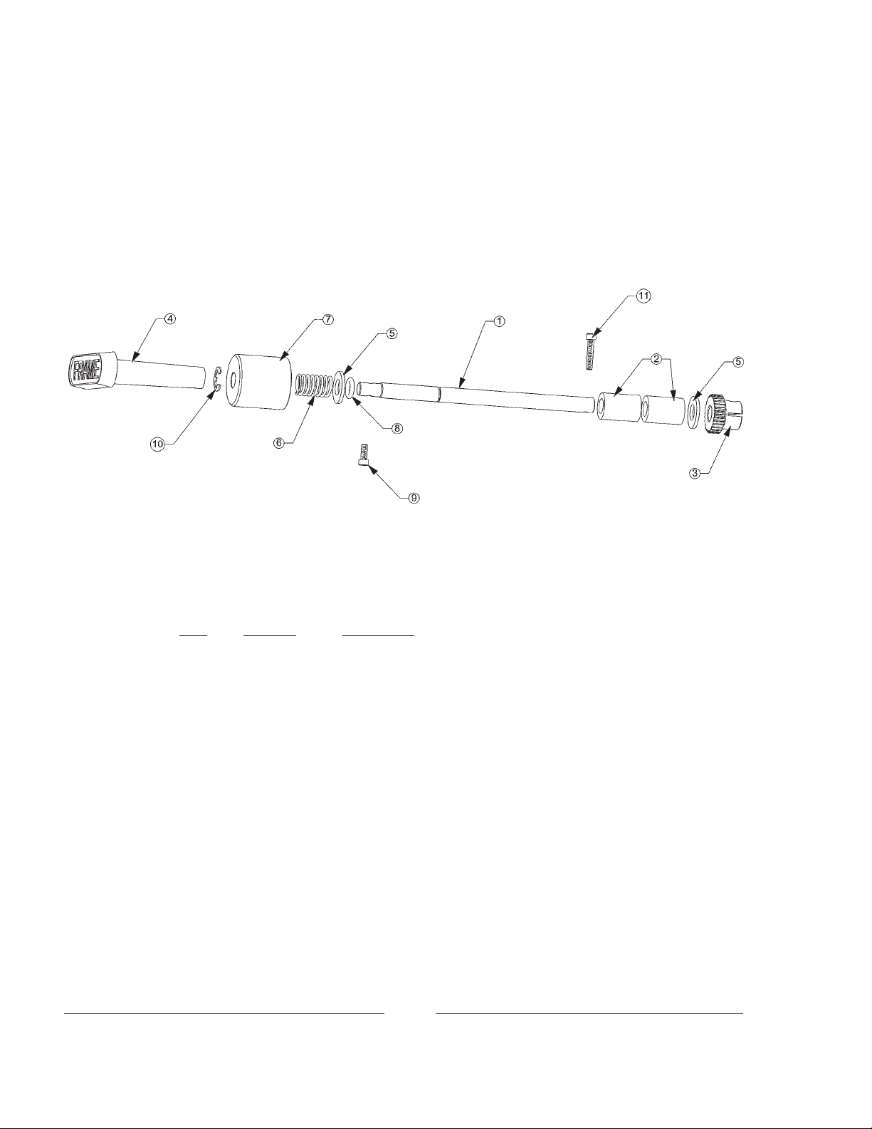
SOUND READER FLYWHEEL INSTALLATION
Spring Washer
Shaft
The sound reader flywheel is dismounted for
shipping to avoid damage to the impedance drum shaft.
Assemble the flywheel to the end of the impedance drum
shaft using the wave spring washer and spacer in the
sequence shown (spring washer against the flywheel,
Spacer
Flywheel
spacer next to bearing seal). Secure the flywheel to the
shaft with the 1/4 inch hex head screw. Note LEFT-
HAND THREAD; turn counterclockwise to tighten.
7
Page 13

SOUND READER ASSEMBLY
ADJUSTMENTS to those components relevant to scanning the optical soundtrack are best
performed by qualified personnel equipped with the necessary test equipment. Attempts to effect field repairs
without use of the required test equipment are generally detrimental to sound quality.
1. An L.E.D. (Light Emitting Diode) is positioned directly behind the film plane to illuminate the soundtrack.
The horizontal and vertical positioning is adjustable. The distance of the L.E.D. from the film plane is
factory set. The L.E.D. is powered by a remote, low-voltage, current regulated power supply.
2. An Analog Signal Pick-Up Assembly is mounted in front of the film plane, and contains the lensing, the
solar cells, pre-amps, and terminals for the cell output. This assembly is factory-set to maximize the
reception of the signal generated by the L.E.D.
3. A second L.E.D. illuminator and signal pick-up are required for scanning Dolby
®
digital prints. These
components are mounted adjacent to the analog elements, 45° off the analog axis. A second L.E.D. power
supply is also required.
An L.E.D. features a much longer life than an incandescent exciter lamp, and eliminates signal loss
because of sagging or aging bulb filaments. The one-piece Signal Pick-Ups detect only L.E.D. inputs, and
stray booth lighting does not affect the solar cell output. Channel separation is enhanced by incorporating the
solar cells within the sealed lens assembly.
Signal Pick-Up Assembly, ANALOG
L.E.D. Illuminators
Impedance Drum
Signal Pick-Up Assembly, DIGITAL
Film Path IN
Holdback
Sprocket
Film Path OUT
8
Page 14
The duty cycle (time ON) of the L.E.D. is the same as the projector motor and should parallel that of the
xenon bulb; the lamphouse elapsed hour meter should indicate approximate L.E.D. hours. L.E.D. manufacturers have noted a 10-20% drop in light output after prolonged operation. If a sound signal loss cannot be
corrected by fader gain, it may be necessary to replace the L.E.D. head.
WIRING
Install the LS-40 L.E.D. Power Supply to the projection console, pedestal, or to a rack adjacent to the
soundhead. Set the slide switch for the desired AC power , and connect to AC source. Route the power leads to the
soundhead-mounted L.E.D. illuminator assembly using 18 gauge wires for short runs; 16 gauge wires for excessively long runs. Other installer connections are made to the clearly-marked terminals on the back of the unit.
The L.E.D.’s are bipolar; the power supply cannot damage an L.E.D. through reversed polarity . It is safe
to try reversing the polarity if you have power but no light. Accidental connection of the L.E.D. to the pre-
amp power terminals will damage the L.E.D. The pre-amp power to the analog reader (Signal Pick-Up) is 12
V .DC+, ground, and 12 V.DC-. The ground must be connected at both ends as it is circuit reference zero volts.
It is recommended to use (2) shielded two-conductor cables to connect the solar cell outputs, but
use of a three-conductor, single-shield cable is permitted. If using three-conductor cable, strap the two “LO”
terminals together. Since very little current is required, 22 gauge wire is adequate. DO NOT interconnect
input and output grounds.
Digital readers utilize a second LS-40 Power Supply. Use 16 or 18 gauge hookup wire between the
L.E.D. and the LS-40 power supply , depending on the length of the run. Pre-terminated digital output cables
(51-98272) are supplied, and should be connected to the processor as instructed in the Dolby manual.
ANALOG ALIGNMENT
Energize the LS-40 and check for 450 mA output to the analog (inner) L.E.D. Connect test equipment to
solar cell output terminals. Turn the sound processor ’s level and high frequency adjustment to minimum
settings.
Loosen, but do not remove, the socket head screw clamping the inner L.E.D. head to its mounting post and
bracket. Loosening this screw permits moving the L.E.D. head up and down, and on the horizontal plane (in
and out). Position the L.E.D. head to visually locate the light source directly opposite the lens opening of the
analog signal pickup assembly .
Run a loop of level set (“Dolby Tone”) film and observe the output of the LEFT and RIGHT channels.
When the highest output is seen, move the L.E.D. head horizontally (in and out) inside the impedance drum.
DO NOT permit the L.E.D. head to touch the inside of the impedance drum. Observe the output and secure the
L.E.D. head when the highest output is achieved. Refer also to the sound processor manual.
Run a “Buzz Track” (SMPTE No. 35-BT) loop and check for correct sound track alignment. It is recommended to splice together a loop of half “Buzz Track” film and half “Left/Right Alignment” (Dolby Cat. No. 97)
test film. This permits centering the soundtrack and checking for cross-talk simultaneously. If correction is
required, loosen or tighten the 1/4-20 locknut to move the spring-loaded pickup assembly horizontally .
9
Page 15

Focus/Azimuth
Analog Signal
Pickup Assembly
Azimuth Adjust
Focus Adjust
Horizontal
Positioning
Locknut
Clamping Screw
L.E.D. Head
Clamping Screw
Impedance Drum
Loosen the focus/azimuth clamping screw and set the focus and azimuth by running the “pink noise” loop
and adjusting the signal pickup assembly in the same manner as a conventional slit lens. Finalize the “A”
chain installation by again checking the L.E.D. adjustment using Dolby Cat. No. 566 “illumination uniformity” test film. Perform a final “Dolby” level set, and complete any other steps specified by the manufacturer
of the sound processor.
DIGIT AL ALIGNMENT
Preliminary Adjustment
• Power up the second LS-40 Power Supply and the Audio Processor.
• Check for 550 mA output to the digital (outer) L.E.D.
• Connect a dual-trace oscilloscope to the left and right test points of the
Analog Soundtrack
processor pre-amp.
• Thread and run Dolby Tone Test film (Cat. No. 96t).
• Observe oscilloscope traces and “Dolby” level indicators in the processor.
• If tone is visible on both channels, set to “Dolby” level.
• If not, check the L.E.D. alignment and focus the optics. Then set
“Dolby” level.
• Thread and run SMPTE “Buzz” track.
• Adjust horizontal positioning locknut as required to obtain (2) very low ,
equal residual signals.
Analog L.E.D. Alignment
The analog L.E.D. must be aligned before the digital.
• Turn both left and right channel pre-amp gain adjustments on your cinema
processor to full down; if using a Dolby CP-500, turn to 50%. The goal is to
have equal gain on both channels.
• Thread and run Dolby Tone Test film (Cat. No. 96t).
• View the pre-amp outputs on the oscilloscope screen.
• Rotate the analog L.E.D. mount assembly to reach the maximum ampli-
tude of both traces.
• Move the assembly laterally to get both traces as high and equal as possible.
• Complete the standard “A” chain alignment.
Digital Soundtrack
10
Page 16

T o minimize microphonics, the L.E.D. must be very accurately aligned.
• With the power amplifiers OFF , turn the processor and monitor gains FULL UP. Select a film format and
the correct projector on the processor. Run the projector with no film. Fine-adjust the L.E.D. mount
rotation to a point where the sound of the projector running is not heard through the sound system. The
optimal adjustment will be found between two positions where the projector vibration can be heard quite
clearly . Run Dolby Tone again to give the system a final adjustment. The final result will be projector
noise that is below the noise floor of the processor.
• Optionally, connect an AC millivolt meter to one of the pre-amp test points. Rotate the L.E.D. mount to
achieve highest output to three decimal places on the AC millivolt meter . Careful peaking will achieve
the same result.
Digital Reader Alignment
• Thread and run a reel of Dolby-encoded film.
• Connect a dual-trace oscilloscope to the Dolby Digital Processor per the following instructions.
• Refer to the oscilloscope traces “A” - “D” on the following page in reference to the following instructions:
Figure B is in optimal alignment.
• In Figure A, the top of the sprocket hole has (12) large saw teeth. The differential between the high and
low points is 1/3 volt.
• Figure B shows more saw teeth with less differential. This is obtained by fine-adjusting the rotation of the
L.E.D. holder.
• In Figure C, the sprocket hole is falling off on the left, indicating uneven light. This is improved by
moving the L.E.D. holder laterally until a flatter trace is obtained.
• In Figure D, the CCD board is misaligned laterally. Dimension X2 is smaller than X1. This can be
improved by loosening the moving the board until the X1 and X2 dimensions look like Figure B. The correct
alignment is offset to the left by one minor division. That is, the sprocket hole will be 1/5 of a square offcenter toward the left “goal post”on the ‘scope screen.
Instructions for Alignment of Readers for Dolby Digital
1. Connect a dual-trace oscilloscope to test points on V ideo Acquisition Card (Cat. No. 605 or 670). Oscillo-
scope should be 20 MHz. minimum.
a) Connect Channel 1 to Video test point; connect this probe ground only to Gnd. test point.
b) Connect Channel 2 to Clamp test point.
c) Set both channels Volt/Div. controls to 1 volt/div. Set vernier to calibrate. Ensure that probes are
not at X10.
d) Set horizontal sweep rate to 2 usec/div.
e) Set trigger to channel 2 and positive polarity, adjust trigger level, and lock on signal.
11
Page 17

(Figure B is in optimal alignment)
12
Page 18

2. Calibrate oscilloscope to processor:
a) Thread a loop of Cat. No. 69P test film into projector and reader; start machine.
b) Select Channel 2 for display .
c) Adjust the horizontal position to line up the inside edge of the left “goal post” with the left edge
of the graticule.
d) Adjust the sweep vernier to line up the inside edge of the right “goal post” with the right edge of the
graticule.
e) Adjust the vertical position for the baseline of the clamp signal (Channel 2) to coincide with
a line in the lower section of the graticule.
f) Select either Alternate or Chop to give the brightest display of both channels.
g) Adjust the vertical position of the video signal (Channel 1) to coincide with the same line as the
clamp signal.
3. Alignment of the Reader:
a) Rotate the horizontal positioning locknut and roughly adjust the lateral position of the CCD board
so that the outer trace (perf) is centered between the “goal posts.” This is approximate, and will
be repeated later for accurate positioning.
b) Rotate the L.E.D. mounting assembly for maximum amplitude on the upper trace without
sacrificing flatness. The trace should vary one block or less (± .5 volt). As shown, Figure B is
improved from Figure C. Amplitude, as measured with the top trace, should be between 2-5
volts from baseline. Adjust the digital L.E.D. for minimum ripple on the upper trace of the video
signal. As shown, Figure B is improved from Figure A.
c) If available, use DRAS10 software and a laptop computer to view the adjustment of azimuth for a
zero degree reading. Or, center the reader rotation between sync lost points using the error rate
of the Digital Processor to indicate lost sync.
d) Adjust focus for darkest center in area of bits (grass). Confirm highest reading with DRAS.
e) Confirm calibration of oscilloscope as above. Readjust the lateral position to align the outer
trace to one minor division (2/10) left of center between the “goal posts.” Figure B is improved
from Figure D.
4. Final Analog:
Check the lateral alignment, as initially set using the “Buzz T rack,” and correct as required.
Confirm the L.E.D. positioning by setting the oscilloscope for “X-Y” display and running the
Dolby Cat. No. 97 loop. A “cross” should appear on the screen. When both the horizontal and
vertical lines are straight and of uniform length, the optimum position has been reached. Repeat
the tests for focus, azimuth, equalization, and “Dolby” level set. A dif ference may be noted in that
the high frequency range is extended, and very little high frequency boost will be required.
13
Page 19

Focus/Azimuth
Clamping Screw
Azimuth Adjust
Digital Signal Pickup
Assembly
Focus Adjust
L.E.D. Head
Clamping Screw
Impedance Drum
Horizontal Positioning Locknut
14
Page 20

START-UP PROCEDURES
ALL SIMPLEX PROJECTORS are carefully “run-in” at the factory before shipping. No
“run-in” period at the installation site is required. Some gear whine may be noticed initially, but should
disappear after a few hours of operation.
INITIAL OILING
One quart of Simplex Projector Oil is included in the accessory kit supplied with new equipment. USE
ONLY GENUINE SIMPLEX PROJECTOR OIL IN THE MECHANISM. Use of other lubricants may
inhibit oil pump operation and damage moving parts. Additional oil is available through authorized Strong
International Dealers; order Simplex Part No. 52-00400 for one-quart quantities, 52-00410 for a half-gallon
can, or 52-00420 for a one-gallon can.
DO NOT, at any time, operate the projector without oil.
With the projector level (0° projection angle), add oil through the filler located at the front of the gear
compartment. Look into the gear compartment while adding oil; the correct amount of oil will touch the bottom
of the horizontal drive shaft. No air bubble should be visible in the sight glass inside the film compartment.
Unless the machine is operated at a severe upward angle, no air should be visible in the sight glass. If
bubbles are seen, add oil to maintain a safe level. Always check the oil level with the motor off.
Normal Add Oil
Rotate the motor flywheel by hand to turn the projector mechanism. It should turn freely and smoothly .
Start the projector motor and run for at least one minute. Check for an oil splash against the gear compartment
cover glass.
15
Page 21

THREADING
Threading the projector correctly is one of the operator’s most important duties. Careful attention
during this operation pays off in improved performances and long print life.
Unlatch and open the turret. Rotate the framing handle (A)
to position the intermittent sprocket (B) at the center of its adjustment range. Using the motor flywheel, turn the mechanism by
hand to rotate the intermittent sprocket (B) to its “rest” position.
In the “rest” position, the intermittent sprocket is in a locked,
stationary stage while the other sprockets continue to rotate.
Open the feed (C) and holdback (D) sprocket pad roller assemblies. Open the film gate by pulling the gate opening pin (E)
and sliding the film gate forward to the threading position. Open
the intermittent sprocket roller arm (F).
At this time, it is advisable to dismount the film gate
pressure pad by sliding the gate to its full forward position, and
loosening the thumb screw (G). W ithdraw the pressure pad runner
from the film compartment and use a clean, dry cloth to wipe
down all film-bearing surfaces of the gate and trap. Replace the
pressure pad after cleaning and secure thumb screw (G). This
procedure should be performed at least once every day .
Thread the film as illustrated. Engage first the intermittent
sprocket (B), and check for correct frame position at the lighted
framing aperture (H). When correct, close the intermittent roller
arm (F). Secure the gate by pushing the gate into the trap until the
spring-loaded gate latching pin (E) engages. Form a two-finger
loop above the gate as illustrated, and on the loop chute below the
intermittent sprocket. Draw the film over the impedance drum (I)
and close the pad rollers over sprockets (C) and (D).
Rotate the motor flywheel by hand to advance a few frames of film. Do not “inch” the mechanism by
momentarily switching the drive motor on and off; in the event of a threading error , film may be damaged. Run
fingers over each sprocket (B, C, & D) to insure that the sprocket teeth are centered in the film perforations,
and the film is centered between the flanges of the pad rollers. Check again the position of the film in the
framing aperture (H). With the intermittent sprocket in its “rest” position, a correct frame image in the framing
aperture insures correct frame positioning in the picture aperture and on the screen. Use the framing handle (A)
to correct misframes. Close and latch the lens turret.
A slight degree of film tension is required above the upper feed sprocket (C) and below the holdback
sprocket (D). This measure prevents the film from snapping upon motor start.
16
Page 22

INITIAL OPERATION
CLEAN ALL FILM-BEARING SURF ACES BEFORE EACH THREADING OPERATION. Check
all sprocket teeth for hooks or burrs; replace if required. Keep all pad rollers clean and operating freely.
Make certain the turret is set to the correct lens and aperture for the desired screen format. FLAT format is
generally used for initial setup of the projection system.
The Film T rap Tension Knob is located at the top of the film trap, and is graduated from “minus” (-) to
“plus” (+). Rotate this knob counterclockwise to its stop. The “minus” (-) setting indicates minimum trap
tension. Thread film into the projector, ignite the lamp, and project a picture to the screen. Use of RP-40 test
film is highly desirable for this stage of machine set-up. This test film may be purchased directly from the
Society of Motion Picture and T elevision Engineers:
SMPTE Test Film Department
595 W est Hartsdale Avenue
White Plains, New York 10607
or
www.smpte.org
Order: 35 PA-50 (50 ft.) or 35 PA-200 (200 ft.)
Install the lenses and set focus as detailed in the preceding INST ALLATION section. File the apertures
to fit screen or masking parameters.
If the projected picture is unsteady , rotate the film trap tension knob clockwise one step at a time, while
the film is running. Always adjust for the minimum tension required to project a steady picture. Excessive
tension not only increases wear on projector parts, but in extreme cases may cause torn perforations and
film breakage.
Check the projected picture for travel ghost. “Travel Ghost” is the term commonly applied to vertical
streaking of lighter areas against a darker area, and is particularly noticeable during opening or closing titles
and credits. If ghosting is apparent, rotate the shutter adjustment knob on the top of the projector until the
ghosting disappears. If the ghost cannot be eliminated by means of this knob, see “Shutter Timing” in the
ADJUSTMENTS AND REPLACEMENTS section of this manual.
The rotation travel of the lens turret is limited by the indexing stop pin mounted to the outer ring of the
turret. The automated turret on the Apogee includes a solenoid which pulls the pin when the turret is in motion.
A compression spring seats the pin when the turret is at rest. When first energized, the autoturret will
automatically index to FLA T mode, if not already in FLA T . The proximity switch on the turret ring will sense
the cueing magnet mounted to the index stop bracket and set the correct picture aperture: one magnet mounted
inboard = FLAT, one magnet mounted outboard = SCOPE, two magnets = SPECIAL (third lens).
In the event of a turret or aperture motor failure, the automatic turret can be operated manually until a
replacement motor is obtained. It is advisable to de-energize the turret control until the replacement motor is
installed. The dual aperture plate can be pushed in or pulled out manually to set the correct format.
17
Page 23

MAINTENANCE
THE PROJECTOR MECHANISM should periodically undergo a careful and thorough
inspection. A regular schedule of adjustments and replacement of wearing parts will insure long life, provide
reliable performance, and minimize downtime.
LUBRICATION
Drain and discard the projector oil after six months of initial operation, and at least annually thereafter.
Clean the oil pump intake filter and the oil reservoir. Replace with genuine Simplex Projector Oil (Part No.
52-00400 Quart; 52-00410 Half Gallon; 52-00420 Gallon) available from Strong International Dealers.
SPROCKETS
Clean sprocket teeth daily with a typewriter brush or used toothbrush (with softened bristles). Examine
each sprocket carefully for wear, undercutting (“hooks”), and/or looseness. Replace as required. Assuming the projector is used for forward-running only , hooked sprockets can be re-used by reversing the sprocket on
its shaft. Check the alignment of the intermittent sprocket to the film trap.
PAD ROLLERS
Check pad rollers for grooves, flat spots, and/or looseness. Clean rollers and shafts thoroughly to relieve
binding; replace as required. Inspect alignment of pad rollers to sprockets; centered, flanges not rubbing,
spaced (2) film thicknesses above sprocket face.
FASTENING HARDWARE
Check all fasteners (screws, nuts) for tightness. Normal operating vibration over prolonged periods may
cause fasteners to loosen. Tighten as required.
FILM GATE
Remove all foreign matter (dirt, wax) by cleaning thoroughly. Examine film runners and straps for wear;
replace if required. Check gate opening and closing slide for smooth operation; clean linear bearing to relieve
binding. The gate mount is adjustable horizontally by means of slotted mounting holes; check periodically to
insure secure gate closure.
FILM TRAP
Examine the inboard spring-loaded studio guides for free motion. Clean carefully , adjust, or replace if
grooved. Remove all foreign material from tension straps. Inspect for wear; replace if required.
To remove the trap from the main frame, release the quarter-turn fastener securing the aperture motor
cover to the shutter guard. Loosen the slotted head of the trap mounting screw. This screw is captive, and
cannot be removed. When the trap mounting screw is loose, grasp the trap plate and withdraw the trap from the
film compartment. Carefully align the electrical pins before replacing the trap.
18
Page 24

MAINTENANCE (continued)
LENS TURRET
Periodically check the condition of the (2) O-ring drive tires on the auto turret drive wheel. Clean the
surfaces of the O-rings and replace if worn or cracked. DO NOT LUBRICA TE. Check the tension of the motor
mount expansion spring and replace if stretched.
The indexing plate of the lens turret rotates on (3) grooved ball bearings mounted to the turret ring
casting. The uppermost bearing is retained by means of an eccentric bushing, allowing a degree of adjustment.
To adjust, loosen the socket head bearing screw, and increase or decrease bearing pressure by rotating the
eccentric bushing with a 9/16 inch end wrench. Do not apply excessive pressure; allow the index plate to rotate
freely , but without “play” between the plate and ring.
On both AUT O and MANUAL turrets, the index stop is actuated by the a compression spring mounted
between the stop pin and the solenoid (or lever). Make certain the spring is correctly installed. Replace
immediately if worn; the correct spring tension is required to seat the index stop pin. The index stops on the
lens indexing plate are mounted with (3) screws each. Two of the mounting holes are slotted to provide a
degree of fine adjustment of the lens position. Securely tighten all (3) screws when the lens is correctly
positioned. See the following ADJUSTMENTS & REPLACEMENTS section for detailed information regarding lens alignment and positioning.
Magnets are mounted to brackets on the index stops to actuate the ring-mounted proximity switch and
establish lens/aperture logic. Periodically clean the exposed surfaces of these magnets to insure good magnetic
conduction. Keep mounting hardware tight to maintain correct alignment.
L.E.D. indicators next to the reset switch display operation of the aperture-sensing proximity switch.
When the center L.E.D. is illuminated, the proximity switch is sensing the inboard magnet, and setting the
FLAT aperture. The lower L.E.D. glows when the proximity switch senses the outboard magnet, and actuates
the SCOPE aperture. The uppermost L.E.D. glowing indicates that the proximity switch senses two magnets,
thereby setting the SPECIAL aperture (third lens, when used).
Clean the turret hinge to allow free operation. Make certain that the turret is fully closed when latched.
The deadstop screw in the front center of the turret casting can be adjusted to remove “play .” Do not shim the
turret, or offset the index stops in an attempt to correct “keystoning.” Keep lenses on correct optical centers.
Clean the lenses as recommended by the lens manufacturer. Do not remove the lenses from the turret for
cleaning; doing so would alter the preset focus of the lenses. Swing the turret open to the THREAD position for
easy access to the rear surfaces of the lenses. Close and latch the turret after cleaning the lenses.
OVERALL APPEARANCE
Clean all enameled surfaces of the projector regularly . Surfaces coated with oil will attract and hold dust
and film particles.
19
Page 25

CHANGEOVER
DOUSER
HEAT
SHIELD
CHANGEOVER
DOUSER
PIVOT
DOUSER LINKAGE
ARM
SHUTTER
BLADE
FIGURE 3
COVER, APERTURE
MOTOR
FILM TRAP
20
Page 26
UPPER FEED
SPROCKET
DRIVEN GEAR
MAIN OIL
SUPPL Y LINE
VERTICAL SHAFT
SHUTTER
SHAFT
DRIVE GEAR
UPPER FEED
SPROCKET
DRIVE GEAR
OIL SLINGER
SHUTTER
ADJUSTMENT
KNOB
INTERMITTENT
MOVEMENT
OIL TRAP
SHUTTER
SHAFT
SUPPORT
INTERMITTENT
DRIVE GEAR
OIL PUMP
HOLDBACK
SPROCKET
DRIVEN GEAR
INTERMITTENT
MOVEMENT
FLYWHEEL
FRAMING
GEAR
HOLDBACK
SPROCKET
DRIVE GEAR
FIGURE 4
21
Page 27

ADJUSTMENTS AND REPLACEMENTS
REFER TO THIS SECTION in conjunction to performing the steps in the MAINTENANCE
section. Conscientious maintenance and service of the Simplex Apogee Projector Mechanism will insure many
years of excellent performance.
ADJUSTMENTS are quickly accomplished, and replacements performed, as all units and
components are readily removed. Adjustments and replacements described below may be performed by
qualified projection booth personnel. Any elements of maintenance and service not detailed below should be
referred to an authorized Strong International Dealer .
FILM TRAP AND APERTURE CHANGER ASSEMBLY
Dismount the aperture motor cover plate (see Parts List, “Film Trap” drawing, Item 53) by releasing the
quarter-turn fastener (Item 54) and loosening the (2) phillips head screws (Item 44). Loosen the captive, slot
head mounting screw (Item 34) and remove the trap assembly from the film compartment.
T o replace, make certain that the contacting surfaces on both the mounting plate and the trap casting are
clean. Align the pins of the electical connector pins and slide the film trap in so that it registers with the (2)
dowel pins in the main frame. Carefully guide the electrical plug into its receptacle for the the aperture change
motor and framing light PC board connection. Securely tighten the captive mounting screw.
Check the alignment of the intermittent sprocket to the film trap (see INTERMITTENT MOVEMENT
section following).
PRESSURE STRAP REPLACEMENT
Dismount the film trap and associated components. Rotate the trap tension knob fully counterclockwise
to the “minus” (–) position. Remove the (2) screws from each strap, and remove the straps. Replace with new
straps and reassemble. NOTE: Project film to reset gate pressure (see START-UP PROCEDURES).
STUDIO GUIDE REPLACEMENT
Remove the film gate runner and open the turret assembly. Remove the (2) socket head screws to dismount the fixed, outboard studio guide. Position and install the replacement outboard studio guide. The two
spring-loaded inboard studio guides, which serve as lateral guides, can be dismounted by removing the (2) slotheaded shoulder screws. Clean the spring channels and inspect the springs for proper tension before replacing.
Close the turret and replace the film gate.
APERTURE PLATE ADJUSTMENT
Gear mesh between the aperture drive motor spur gear and the rack gear on the aperture slide can be set
by loosening the (2) 10-32 socket head screws and moving the motor, on its mounting plate, up or down. The
motor plate mounting holes are slotted for this purpose.
22
Page 28
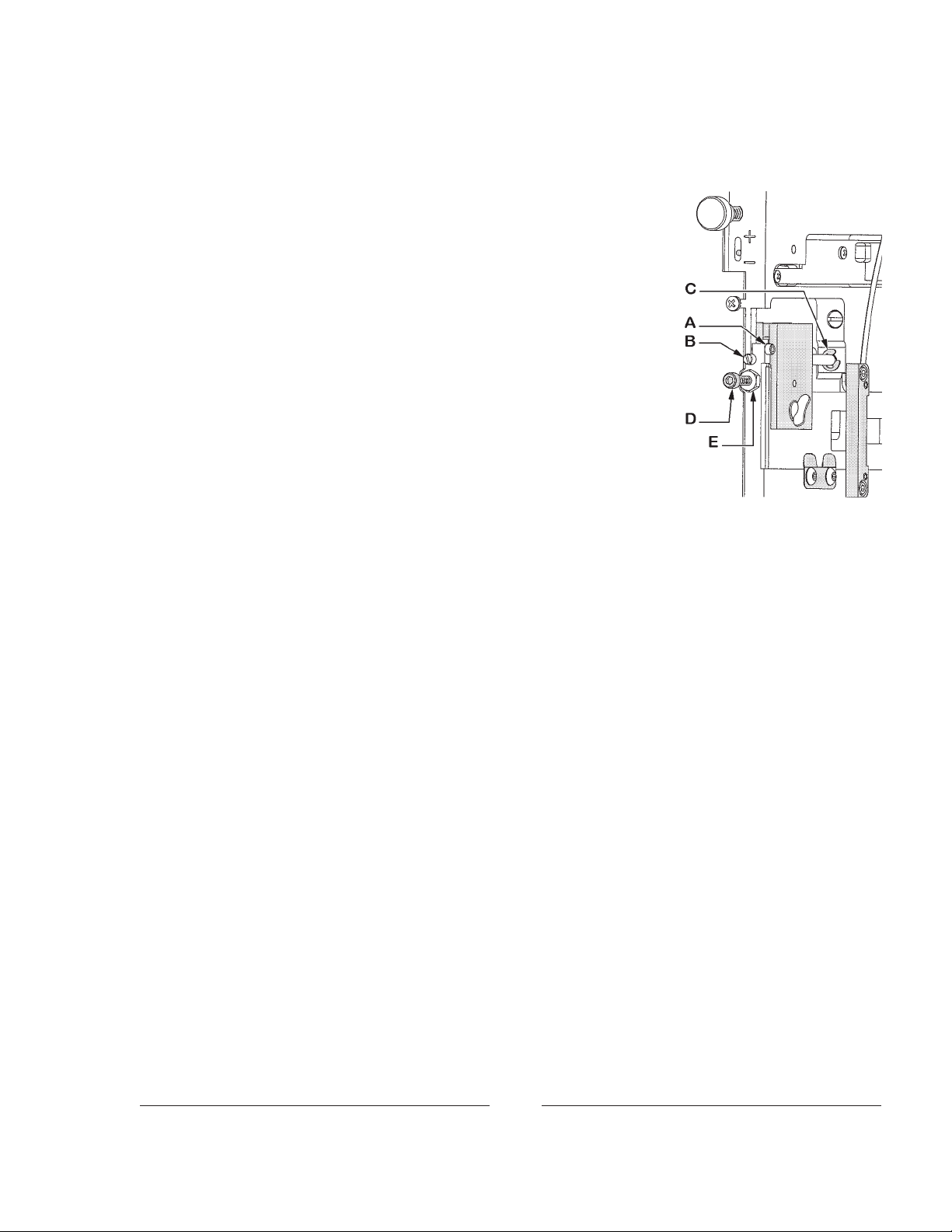
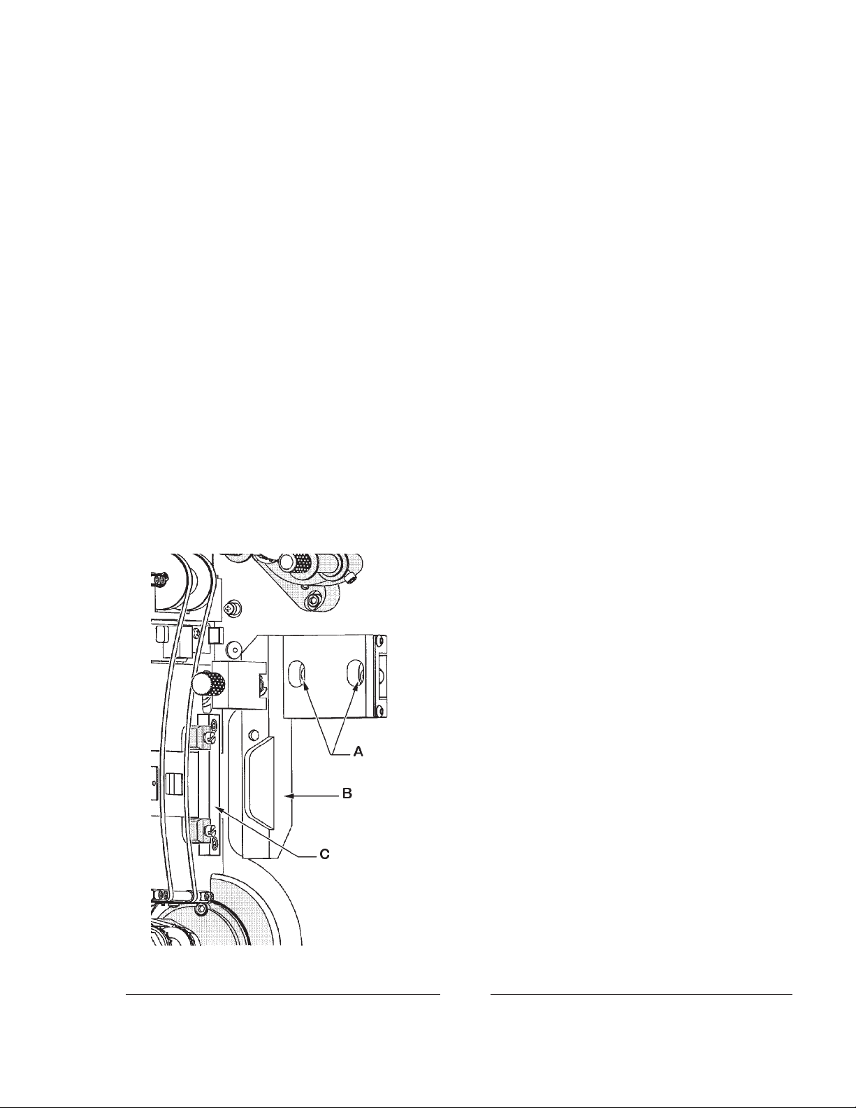
APERTURE PLATE ADJUSTMENT (continued)
Horizontal travel of the aperture plate is also adjustable. The inboard
stop is set by loosening the clamping screw (A) and rotating the slotted end of
the slide shaft (B) to position the snap ring (C) at the desired stop point.
Secure the clamping screw (A) after the adjustment is correct. The outboard
stop is fixed by tightening or loosening stop screw (D) against the aperture
slide bracket. Secure lock nut (E) after the outer stop adjustment is correct.
GEAR COMPARTMENT COVER REMOVAL
Remove the gear compartment cover only when absolutely necessary ,
and only after the machine has been at rest for at least (10) minutes to allow all
oil to drain into the reservoir. Remove the cover fastening screws. Make
certain no foreign material deposits in the gear compartment while the cover
is removed. Before replacing the cover, wipe all oil from the cover gasket and
the mating surface on the projector main frame. Any oil remaining on these
surfaces will provide an oil seepage path after the cover is replaced. Tighten all
screws equally and in sequence, and secure enough to form an oil-tight seal.
INTERMITTENT MOVEMENT REPLACEMENT
1. Open the film gate. Rotate the framing handle fully clockwise.
2. Set the shutter adjusting knob in mid-position. The shutter adjusting knob travels three complete turns.
T o locate mid-position, rotate the knob to either stop, and reverse 1½ turns.
3. Remove the gear compartment cover (see above).
4. Rotate the vertical shaft until the intermittent drive gear mounting screw is visible. Remove the mounting
screw and slide the gear downward.
5. Loosen the (2) intermittent retaining clamp screws on the framing cam and position the clamps to clear the
intermittent case.
6. W ithdraw the intermittent assembly from the gear compartment side, taking care not to strike the inter-
mittent oil feed tube positioned above the intermittent assembly.
7. Slide the replacement intermittent movement into position. The keyway in the intermittent case is aligned
with the key in the framing cam. Press firmly to seat the O-ring.
8. Rotate the intermittent retaining clamps to retain the intermittent assembly and tighten the fastening
screws securely .
9. Rotate the shutter counterclockwise (from the rear of projector) until its leading edge is exactly in line
with the upper edge of the picture aperture (aperture just completely blocked).
10. Rotate the intermittent flywheel until the intermittent sprocket turns clockwise; (1) of the (4) index lines
on the outboard collar will align with the index line on the outboard bearing support arm.
11. Continue to rotate the flywheel in the same direction until the intermittent sprocket just begins to move.
12. Reverse rotation of the flywheel until the sprocket stops. Then, rotate the flywheel counterclockwise
until the start of sprocket rotation is felt.
13. Continue to rotate the flywheel until the precise point at which the sprocket is about to move is reached.
Retain that setting.
14. Raise the intermittent drive gear and rotate it tooth by tooth until it meshes with the intermittent driven
gear. At this time, the mounting hole in the drive gear should align with the hole in the vertical shaft. Do
not rotate the vertical shaft or driven gear. Replace the gear mounting screw.
15. Align the intermittent sprocket with the film trap (see below).
23
Page 29

INTERMITTENT SPROCKET REPLACEMENT
1. Remove the film gate runner . Dismount the film trap. Open the intermittent sprocket pad arm.
2. Rotate the framing knob to its extreme clockwise position to expose the intermittent sprocket film stripper
mounting screw . Remove the screw and stripper .
3. Turn the projector mechanism by hand so that one of the collar index lines (A) aligns with the index mark
on the outboard arm (B), and the sprocket mounting screw is exposed.
4. Remove the intermittent sprocket mounting screw and nut.
5. Loosen the (2) intermittent outboard collar set screws and remove the collar (C).
6. Remove the (2) outboard arm socket head mounting screws and dismount the outboard arm (D).
7. Remove the worn intermittent sprocket. Slide the replacement sprocket onto shaft.
8. Position the intermittent outboard bearing arm (D) on the intermittent sprocket shaft and start the (2)
socket head mounting screws finger tight. Adjust the bearing arm, as required, so that the bearing is
precisely centered with respect to the intermittent shaft. Tighten the (2) mounting screws.
9. Fasten the replacement intermittent sprocket to the intermittent shaft using the screw and nut supplied.
10. Slide the intermittent outboard collar (C) onto the intermittent shaft and align one of its index lines (A) to
the index mark on the outboard bearing arm (B). Pull the intermittent sprocket out while pressing the
outboard collar in, so that shaft end play is just perceptible.
11. Securely tighten the (2) set screws in collar (C). Check that the
shaft end play is just perceptible.
12. Replace intermittent sprocket film stripper .
13. Align the intermittent sprocket (see below).
14. Replace film trap and install the film gate runner .
INTERMITTENT SPROCKET ALIGNMENT
Loosen the intermittent sprocket fastening screw and slide the sprocket, as required, until the outside face
of the sprocket is flush with a straight edge (i.e. machinist’s steel pocket ruler) placed on the outside face of the
lower holdback sprocket. Securely tighten the intermittent sprocket fastening screw . Thread a length of scrap
film through the trap between the upper sprocket and the intermittent sprocket to verify correct alignment.
FRAMING LIGHT REPLACEMENT
Remove the film trap. Dismount the L.E.D. Printed Circuit Board assembly from the trap plate (three
screws); replace with new unit (Part No. 52-00353). Align the pins of the electical connectors and slide the film
trap in so that it registers with the (2) dowel pins in the main frame; secure the captive mounting screw.
FEED AND HOLDBACK SPROCKET PAD ROLLER ADJUSTMENT
For coarse adjustment, loosen the three socket head mounting screws securing the pad roller assembly to
the main frame. Position the pad roller assembly so the rollers are at an equal distance from the face of the film
sprocket. Secure the three screws.
For fine adjustment, loosen the socket head screws securing the roller shafts to the roller arm. The shafts
are eccentric; rotating the shaft will move the roller closer to or farther from the sprocket face. Rotate each
roller shaft to position each roller (2) film thicknesses from the face of the sprocket. If the roller cannot be
placed at this position, reset the coarse adjustment. Secure the shafts after reaching the correct setting.
24
Page 30
SHUTTER TIMING
1. Place the shutter adjusting knob in its mid-position. To locate mid-position, rotate the knob to its stop,
and reverse 1½ turns. Remove the shutter guard.
2. Turn the projector mechanism by hand so that the index mark on the intermittent outboard bearing arm
is centered between two of the collar index lines.
3. Loosen the (2) socket head shutter hub clamping screws. With the screws loosened, the shutter blade
should rotate freely on its shaft while the shaft remains stationary.
4. Hold the motor flywheel to “freeze” the mechanism, so the shutter shaft remains stationary . Rotate the
shutter to the fully closed position (one blade completely covering the picture aperture).
5. Tighten the (2) hub clamping screws while the shutter shaft remains stationary.
6. Replace the shutter guard. Project a picture and check the screen; a slight adjustment of the shutter fine
adjustment knob on the top of the projector may be required to eliminate travel ghost (see preceding
START-UP PROCEDURES).
SHUTTER REPLACEMENT
Remove the shutter guard. Disconnect the linkage to the changeover douser. Remove the (4) socket
head mounting screws from the rear cover casting, and dismount the cover. Loosen the (2) shutter hub
clamping screws and dismount shutter. Install the replacement shutter and set shutter time as detailed in the
preceding section. Replace the rear cover, douser linkage, and shutter guard.
FILM GATE PRESSURE PAD & CARRIAGE REPLACEMENT
1. Open the turret. Dismount the gate pressure pad runner
by loosening the captive thumb screw and removing the
runner from the gate carriage.
2. Remove the sliding gate carriage and bearing assembly
after dismounting the pressure pad runner. Slide the film
gate carriage back to the “closed” position to expose the
two socket head mounting screws (A). Remove the
mounting screws and withdraw the carriage and bearing
assembly (B) from the film compartment.
3. To replace the film gate carriage assembly , install it to the
main frame using the two socket head mounting screws
(A). Do not tighten the mounting screws until aligning the
gate carriage (B) to the trap.
4. Close the film gate carraige and check the alignment between the gate carriage and the trap. The pressure pad
plate must be parallel to the trap. Set the spacing between
the gate carriage and the trap by placing a 9/64 inch allen
wrench between the face of the inner studio guide spring
block (C) and the gate carriage (B) with the carriage closed.
Hold the carriage in place (against the allen wrench) and
securely tighten the two mounting screws (A).
5. Replace the pressure pad runner. Close and latch the
turret. Set the trap tension to “minus” (–). Project some
film and check the picture for stability . Reset trap tension
as required.
25
Page 31

FILM SPROCKET REPLACEMENT
1. Open the pad roller arm.
2. Remove the hex head sprocket fastening screw from the outboard end of the sprocket shaft and slide the
sprocket from the shaft. Leave the spring washer and flat washer on the shaft.
3. Slide the replacement sprocket onto the sprocket shaft, aligning the key in the sprocket with the keyway in
the shaft. Secure with the sprocket fastening screw .
FILM SPROCKET DRIVEN GEAR REPLACEMENT
1. Remove the gear compartment cover (see previous).
2. Remove gear fastening screw and slide gear from shaft.
3. Hold the film sprocket in place and slide the replacement gear onto the shaft. Insert the fastening screw ,
position the gear to allow slight end play , and securely tighten the fastening screw.
4. Replace the gear compartment cover .
AUTOMATIC LENS TURRET
1. Check for correct contact between the turret drive tires and the driven indexing plate. Clean surfaces to
prevent dust and dirt build-up; replace O-ring tire(s) if cracked or worn. Do not lubricate.
2. Clean the grooves in the (3) indexing plate ball bearings. The top bearing is mounted to an eccentric
bushing to permit adjustment; take up any slack as required.
3. Check the compression spring on the index stop pin. Replace with
new, or stretch to length. Check the expansion spring on the motor
mount and replace if excessively stretched and allowing slippage.
4. A headless set screw in the front center of the turret casting (see Figure
1) acts as a deadstop for turret closure. Tighten this screw as required to
remove any play from the turret hinge when closed, yet allowing the
turret to latch securely . T ighten the hex nut to lock this adjustment.
NOTE: Do not attempt to correct “keystoning” by setting this deadstop
screw to offset the projection lenses. Lenses must remain on optical
center for correct focus.
5. Periodically check lens positions and correct as required. Project RP-40
Test Film to the screen and alternate between formats. If the picture
noticeably shifts up and down or left to right between formats, the lenses
should be re-positioned.
5a. The index stops are mounted to the inside of the lens indexing plate with
three screws. T wo of the screw holes are slotted to permit fine adjustment of the vertical lens position. Adjust the up-and-down position of
the picture on the screen by loosening the two locking screws (A) and
turning the slot-headed eccentric stud (B). When the up-and-down lens
position is correct, securely tighten the two locking screws (A).
5b. Left-to-right positioning of the picture on the screen is adjusted by setting the two button head socket
screws (C) adjacent to the lens on either side of the focus knob (D). Loosen the screws (C) slightly using
a 3/16" allen wrench, and adjust the side-to-side position using a 7/32" allen wrench to rotate the adjusting
screw (E). This moves the horizontal eccentric adjustment. Securely tighten the two button head screws
(C) when the picture is correctly positioned horizontally .
26
Page 32

AUTOMATIC LENS TURRET (continued)
6. If a lens change fails to execute when cued, press the reset switch until the desired format is in place.
Check the condition of the cuing material; foil tape may be worn, or bar code information may be
obscured by scratches or dirt. Check for faulty cue detector or failed contact in automation controller.
7. A malfunction in aperture/turret logic indicates a problem in the turret control board. Consult the factory .
There are no user-serviceable components on the printed circuit board.
8. Periodically check the condition of the magnets mounted to the index stops; clean the surfaces of the
magnets to allow good conduction. These magnets are sensed by the proximity switch on the turret ring to
determine aperture logic. A single magnet mounted inboard denotes FLAT, a single magnet on the
outboard edge denotes SCOPE, and two magnets (inboard and outboard) indicate SPECIAL (three-lens
turret only). The magnets are to be positioned close enough to the proximity switch to permit accurate
detection, but should not obstruct turret rotation.
9. L.E.D. indicators next to the reset switch display operation of the aperture-sensing proximity switch.
When the center L.E.D. is illuminated, the proximity switch is sensing the inboard magnet, and setting the
FLAT aperture. The lower L.E.D. glows when the proximity switch senses the outboard magnet, and
actuates the SCOPE aperture. The uppermost L.E.D. glowing indicates that the proximity switch senses
two magnets, thereby setting the SPECIAL aperture (third lens, when used). Failure of the L.E.D. indicator, and/or failure of the aperture to cycle, means that the magnet(s) or the proximity switch are loose or
out of alignment; adjust as required.
27
Page 33

PARTS LISTS
Simplex Apogee
Item Part No. Description
1 51-59005 Film Sprocket, Type VKF
®
- 51-51033 Sprocket Retaining Screw
- 51-70023 Wave Spring Washer
- 51-70024 Thrust Washer
- 51-52017 Sprocket Shaft, Upper & Lower
- 51-04025 Shaft Bearing, Film Side
- 52-00370 Shaft Bearing, Gear Side
- 51-00185 Driven Gear, Upper & Lower
2 52-00284 Gear Compartment Cover
- 31-71017 Oil Seal Cord (order 4 feet)*
- 4110751 Mounting Screw, 10-24 x 3/4"
- 41-07102 Black Fiber Washer, #10
3 52-00282 T urret Hinge Bracket (2 req’d.)
- 4250755 Mounting Screw, 1/4-20 x 3/4"
Item Part No. Description
4 52-00323 Turret Catch
- 52-00396 Lock Nut, 1/2-13 Hex
5 52-00291 Strike Plate, Deadstop Screw
- 4040253 Screw, 4-40 x 1/4"
6 21-38016 Brass Elbow, 90°
- 21-36005 Oil Fill Cup
- 21-38017 Threaded Nipple
7 51-37032 Turret Hinge Pin (2 req’d.)
- 425050A Set Screw, 1/4-20 x 1/2"
8 52-00050 Framing Cam
9 51-98201 Petcock, Oil Drain
- 51-26001 Drain Hose (order by foot)
10 51-98200 Oil Sight Glass
11 52-00325 Main Frame Casting
* T o prevent oil leakage, begin installing replacement cord at the top of the cover, and do not stretch the cord
28
Page 34

FILM GATE
Assembly No. 52-00214
Item Part No. Description
1 52-00209 Gate Carriage & Bearing Assembly
2 52-00212 Film Gate Runner
3 52-00211 Support Plate, Gate Release
4 52-00213 Gate Runner Retaining Screw
5 81-58016 Compression Spring, Gate Release
6 81-56012 Gate Release Spacer
7 52-00350 Pin Assembly, Gate Release
8 21-48016 Retaining Ring, 1/4" External
9 81-48007 Snap Ring, Truarc
10 21-37001 Dowel Pin, 1/2" x 1/4" Diameter
11 4060751 Screw , 6-32 x 3/4" Socket Head
29
Page 35

FILM TRAP
Assembly No. 52-00223
30
Page 36

FILM TRAP & APERTURE CHANGER
Parts List
Item Part No. Description
1 52-00215 Film Trap Base Plate
2 52-00217 Tension Strap Shaft, Lower
3 52-00218 Tension Strap Shaft, Upper
4 52-00219 Upper Tension Shaft Spacer
5 52-00220 Tension Spring Shaft
6 52-00221 Dual Aperture Plate
7 52-00222 Tension Strap (2 req’d.)
8 52-00224 Studio Guide, Fixed
9 82-00115 Slider Bracket
10 81-98141 Rack Gear
11 81-10016 Clamp Plate
12 52-00225 Tension Lever
13 52-00226 Tension Indicator
14 52-00227 Aperture Motor Mount
15 52-00228 Motor Cover
16 52-00229 Studio Guide, Movable (2 req’d.)
17 52-00230 Spring Holder, Studio Guides
18 52-00216 Upper Tension Strap Mount (2 req’d.)
19 71-37002 Dowel Pin, 1" x 1/4" Diameter
20 51-10013 Aperture Clamping Spring
21 52-00345 Dual Aperture Plate Slide Rod
22 4040621 Screw, 4-40 x 5/8" Socket Head
23 4040373 Screw, 4-40 x 3/8" Socket Head (8 req’d.)
24 4080253 Screw, 8-32 x 1/4" Button Head (2 req’d.)
25 4060372 Screw, 6-32 x 3/8" Socket Head (4 req’d.)
26 21-51032 Shoulder Screw, .25" x .25" 10-24 Thrd.
27 4040252 Screw, 4-40 x 1/4" Socket Head (2 req’d.)
28 4100500 Screw, 10-32 x 1/2" Socket Head (2 req’d.)
29 408037C Set Screw, 8-32 x 3/8"
30 21-37030 Roll Pin, 3/8" x 1/16" Diameter (4 req’d.)
31 21-48016 Snap Ring, Truarc 5100-25 (2 req’d.)
32 21-58032 Compression Spring (2 req’d.)
33 81-48002 Retaining Ring
34 52-00352 Trap Mounting Screw, Captive
35 51-48017 Retaining Ring (for Item 34)
36 52-00231 Tension Adjusting Knob
37 4252002 Set Screw, 1/4-20 x 2"
38 52-00232 Shoulder Screw, S tudio Guide (2 req’d.)
39 4040120 Screw, 4-40 x 1/8" Pan Head (7 req’d.)
40 52-00353 Printed Circuit Board Assembly, Motor/Frame Light
- 52-00357 Wire Harness, Trap PCB to Controller Cabinet
31
Page 37

FILM TRAP & APERTURE CHANGER, Parts List (continued)
Item Part No. Description
41 21-37008 Dowel Pin, 1/2" x 1/8" Diameter (2 req’d.)
42 52-00359 Aperture Plate Drive Motor Assembly
- 81-33017 Gear Motor; 12 V.DC, 72 rpm
- 82-20371 Spur Gear
- 4060123 Set Screw, 6-32 x 1/8
- 21-37055 Molex Plug, (2) Pin
- 41-98055 Grommet, Rubber
43 51-37009 Groove Pin, 1/4" x 1/8" Diameter
44 4060250 Screw, 6-32 x 1/2" Pan Head (4 req’d.)
45 81-37011 Spring, Aperture Catch
46 4030181 Screw , 3-48 x 3/16" Socket Head (2 req’d.)
47 51-70037 Washer , #3 (2 req’d. with Item 46)
48 4040620 Screw, 4-40 x 5/8" Pan Head (2 req’d.)
49 82-20448 Bushing
50 81-98121 Latching Stud, Wing Head
51 81-37022 Dowel Pin, 1.125" x .125" Diameter
52 51-58007 Expansion Spring, Strap Tension
53 52-00375 Aperture Motor Cover
- 52-00452 Sticker, “Threading Diagram” (not shown)
54 31-98209 Fastener, Quarter-Turn
DETAIL, Item 42
4060123
82-20371
81-33017
32
Page 38

TRAP BLOWER
Assembly No. 52-00387
Item Part No. Description
1 52-00338 Trap Heat Sink
2 52-00339 Heat Shield
3 52-00343 Air Channel
4 4060250 Screw, 6-32 x 1/4"
Pan Head (4 req’d.)
Blower Power Supply 51-98422 (OMROM T ype S85K, not shown) not included with 52-00387; order separately
Item Part No. Description
5 52-00379 Plug, Air Channel
6 51-02002 Blower, 12 V.DC
7 51-02003 Blower Grille
8 4081250 Screw, 8-32 x 1-1/4" Button
Head, (8 req.d.)
33
Page 39

APOGEE LENS TURRET
Assembly No. 52-00279
34
Page 40

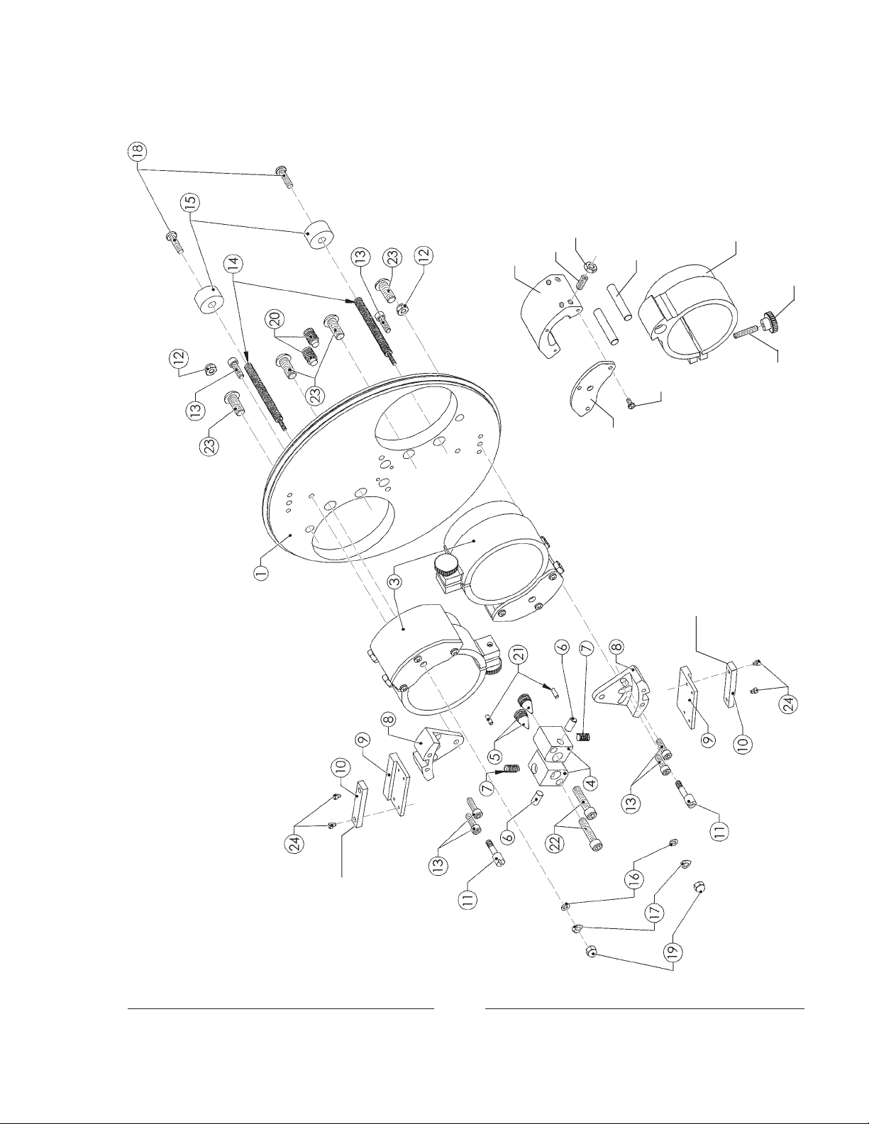
APOGEE LENS TURRET
Parts List
Item Part No. Description
1 52-00272 Turret Ring Casting
2 51-07012 Straight Bushing (2 req’d.)
3 51-49010 V -Groove Bearing (3 req’d.)
4 4257102 Washer, 1/4" I.D. 5/8" O.D. (3 req’d.)
5 4251250 Screw , 1/4-20 x 1-1/4" Socket Head (3 req’d.)
6 52-00263 Turret Lens Plate Assembly, Two-Lens
- Turret Lens Plate Assembly Three-Lens (not shown)
7 51-07013 Eccentric Bushing (Top Position only)
8 52-00268 Motor Bracket
9 52-00267 Motor Spacer Bracket
10 4060310 Screw, 6-32 x 5/16" Pan Head (3 req’d.)
11 52-00355 T urret Drive Gear Assembly
- 51-23005 Driven Gear
- 52-00265 Shaft, Drive Gear
- 51-37011 Roll Pin, 3/32" x 9/16"
12 4257108 Shim W asher, .021" Thick (2 req’d.)
13 52-00269 Motor Bracket Spacer
14 52-00270 Drive Wheel Positioning Block
15 4060372 Screw, 6-32 x 3/8" Socket Head (4 req’d.)
16 52-20613 T urret Plate Drive Wheel
17 4100252 Set Screw, 10-32 x 1/4"
18 21-48001 Drive Tire (2 req’d.)
19 52-00271 T urret Drive Motor Assembly
- 51-33004 Motor, 12 V.DC
- 21-40019 Molex Plug, (2) Pin
- 31-62007 Molex Pin (2 req’d.)
- 51-23011 Worm Gear
- 21-37026 Roll Pin, 3/32" x 3/8"
20 4040250 Screw, 4-40 x 1/4" Pan Head (3 req’d.)
21 52-20641 Spring Retaining Rod (P-7843)
22 21-51032 Shoulder Screw, 1/4" x 1/4" Dia. 10-24 Thrd. (2 req’d.)
23 52-00480 Motor Stabilizing Bracket
24 51-58018 Motor Tensioning Spring (P-2807)
25 52-00337 Motor Housing Assembly
26 52-00363 Turret Switch & L.E.D. Assembly
27 41-98049 S tandoff, 4-40 x 1/2" Nylon (2 req’d.)
28 4048001 Hexnut, 4-40 (2 req’d.)
29 4040251 Screw, 4-40 x 1/4" Button Head (2 req’d.)
30 52-00340 Cover, Motor Housing
35
Page 41

LENS TURRET, Parts List, continued
Item Part No. Description
31 4060250 Screw, 6-32 x 1/4" Pan Head
32 52-00322 Turret Latch
33 51-51011 Shoulder Screw (2 req’d.)
34 21-58060 Compression Spring
35 4370500 Set Screw, 3/8-16 x 1/2"
36 4372005 Deadstop Set Screw, 3/8-16 x 2-1/4"
37 4378001 Deadstop Lock Nut, 3/8-16 Hex
38 52-00277 Sensor Board Mounting Bracket
39 52-00278 Aperture Logic Sensor Board
40 51-56002 Spacer, Nylon (3 req’d.)
41 4040372 Screw, 4-40 x 5/8" Button Head (3 req’d.)
42 4060370 Screw, 6-32 x 3/8" Pan Head (for Item 38)
43 51-04015 Oilite Bushing, Index Stop Pin
44 52-00275 Solenoid Mounting Bracket
45 4080250 Screw, 8-32 x 1/4" Pan Head
46 52-00273 Index Stop Pin
47 52-00274 Index Stop Pin Pivot Plate
48 51-98254 Clevis Pin, 1/8" (P-7966), 2 req’d.
49 01704000 Spring Pin (2 req’d.)
50 52-00397 Solenoid, 12 V.DC
51 51-58059 Compression Spring
52 52-00346 Solenoid Cover Assembly
53 51-37032 Hinge Pin, 2-1/4" x .5" Dia. (2 req’d.)
54 52-00282 Hinge Bracket (2 req’d.)
- 4250755 Mounting Screw , 1/4-20 x 3/4" Socket Head
55 21-70016 Fiber Washer, .505" I.D. x 3/4" O.D.
56 425050A Set Screw, 1/4-20 x 1/2" (2 req’d.)
NOT SHOWN
52-00451 Wire Harness, Motor & Solenoid to Controller
52-00453 Wire Harness, Selector Switch to Controller
36
Page 42
TURRET LENS PLATE
Assembly No. 52-00263
3a
3b
3c
3i
3d
3h
for FLAT cue
Magnet INBOARD
3e
3f
3g
Magnet OUTBOARD
for SCOPE cue
37
Page 43

TURRET LENS PLATE ASSEMBLY
Parts List
Item Part No. Description
1 52-00258 Indexing Plate, Two-Lens
- 52-00259 Indexing Plate, Three-Lens (not shown)
2 52-00320 Labels (not shown) FLAT - SCOPE
3 52-00257 Lens Barrel Assembly (includes Items 14,16,17,19)
3a 52-00255 Slide Mount
3b 4100626 Set Screw, 10-32 x 5/8" (4 req’d.)
3c 4108001 Lock Nut, 10-32 (4 req’d.)
3d 52-20596 Slide Rod (2 req’d.)
3e 52-00254 Lens Barrel Casting
3f 21-28022 Knob, Black Plastic
3g 4101005 Set Screw, 10-32 x 1"
3h 4060310 Screw, 6-32 x 5/16" Pan Head (3 req’d.)
3i 52-00256 Lens Mount, Rear Cover Plate
4 52-00260 Spring Housing Block
5 52-00261 Horizontal Adjust Screw
6 52-00262 Push Rod
7 21-58040 Compression Spring
8 52-20769 Catch Bracket, Index Stop
9 52-00281 Magnet Mounting Bracket
10 51-61017 Bar Magnet
11 52-20618 Eccentric Screw , Index Stop Adjust
12 4108002 Hexnut, 10-32 NyLock
13 4100620 Screw , 10-32 x 5/8" Socket Head
14 52-20604 Focus Shaft
15 21-28010 Focus Knob
16 4067101 Flatwasher, #6
17 21-70028 Wave Spring Washer, #6
18 4100751 Screw, 10-32 x 3/4" Pan Head
19 4068002 NyLock Nut, 6-32
- 4068004 Hexnut, 6-32 (not shown)
20 4370620 Set Screw, 3/8-16 x 5/8" Dog Point
21 01513210 Roll Pin, 1/16 x 5/8"
22 4251250 Screw , 1/4-20 x 1-1/4" Socket Head
23 4320750 Screw , 10-32 x 5/8" Button Head
24 4040121 Screw , 4-40 x 1/8" Socket Head
38
Page 44

TURRET CONTROL BOX
Assembly No. 52-00385
10 4060310 Screw, 6-32 x 5/16" Pan Head (2 req’d.)
11 4067100 Flatwasher, #6 (2 req’d.)
12 4068001 Hexnut, 6-32 (2 req’d.)
13 31-98209 Fastener, Quarter-Turn
14 31-98200 Receptacle, Quarter-Turn Fastener
15 4060250 Screw, 6-32 x 1/4" Pan Head (20 req’d.)
16 41-98090 Standoff (5 req’d.)
17 408025D Screw, 8-32 x 1/4" Pan Head (5 req’d.)
Item Part No. Description
1 52-00383 Box, Welded Assembly
2 52-00386 Transformer
Item Part No. Description
3 41-98097 Standoff, 1/4" x 3/4" 6-32 Thrd. (4 req’d.)
4 4061500 Screw, 6-32 x 1-1/2" Pan Head (4 req’d.)
5 52-70077 PC Board Assembly, “Power”
6 61-98022 Standoff (4 req’d.)
18 51-13006 Ribbon Cable Connector
7 52-70080 Relay PC Board Assembly
8 52-70081 PC Board Assembly, “Control”
9 --- Capacitor, 7.5 µf, 370 V.AC (with Motor)
39
Page 45
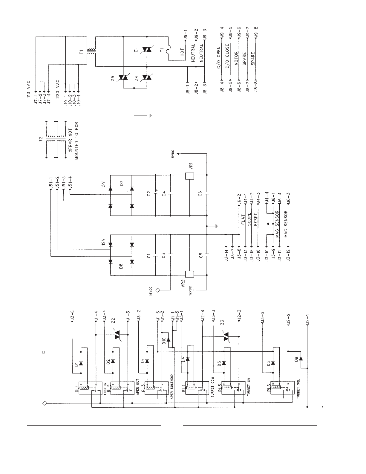
CONTROL CABINET, Wiring Diagram
40
Page 46
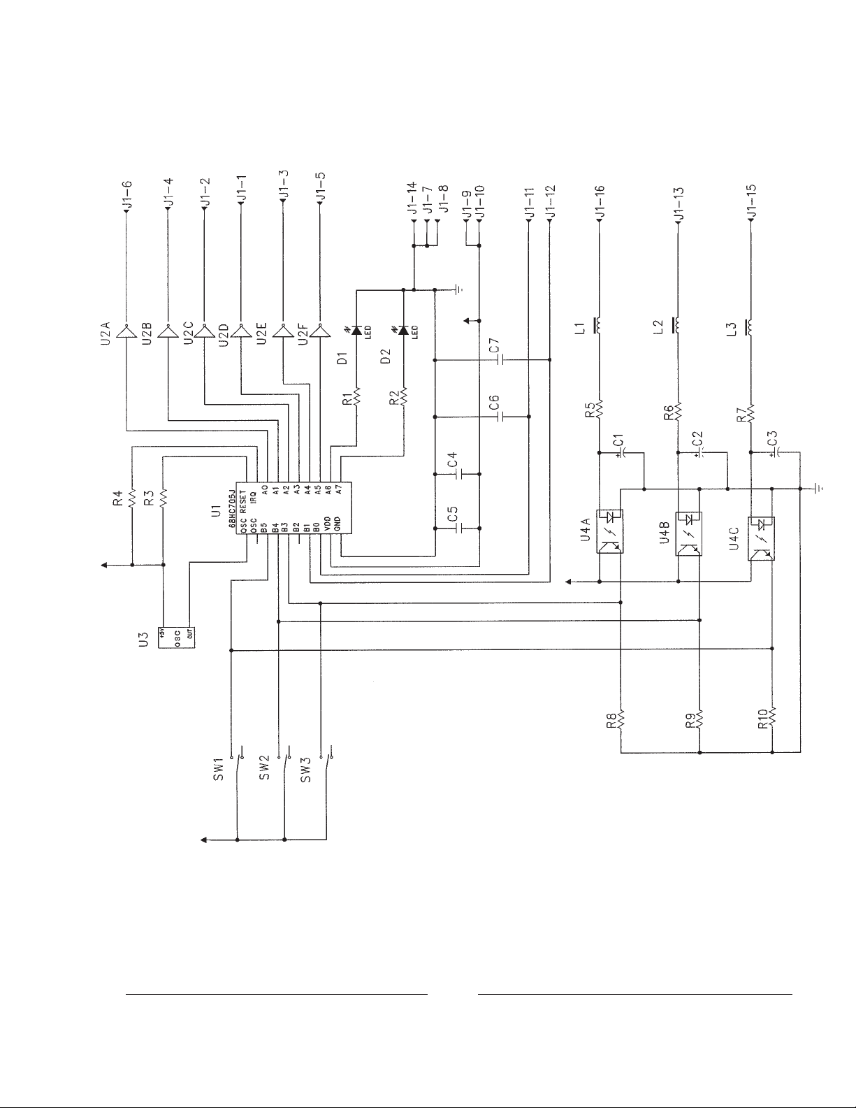
REPLACEMENT CHIP (U1),
Programmed
52-00391: Two-Lens
52-00392: Three-Lens
TURRET CONTROL PRINTED CIRCUIT BOARD
41
Wiring Diagram
Page 47
FRAMING SHAFT
Assembly No. 52-00205
Item Part No. Description
1 52-00207 Framing Shaft
2 51-04004 Linear Bearing (2 req’d.)
3 52-00206 Framing Gear
4 51-28028 Framing Handle
5 4507100 Flatwasher, 1/2" (2 req’d.)
6 51-58036 Compression Spring
7 52-00336 Framing Cover
8 21-48024 O-Ring
9 4100500 Screw, 10-32 x 1/2" Socket Head
10 51-48010 Snap Ring, Truarc
11 4101000 Screw, 10-32 x 1" Socket Head
42
Page 48

HORIZONTAL DRIVE SHAFT
Assembly No. 52-00235
Item Part No. Description
1 52-00234 Horizontal Drive Shaft
2 21-48027 Snap Ring, Truac 5100-50 (3 req’d.)
3 51-27004 Woodruff Key (P-1537)
4 52-00166 Main Drive Gear
5 51-04007 Ball Bearing (2 req’d.)
6 52-00335* Seal Plate Assembly
- 4080375 Mounting Screw, 8-32 x 3/8" Pan Head
6a 52-00233 Seal Plate
6b 51-36011 Oil Seal
6c 51-48007 O-Ring (2 req’d.)
* Item 6 not included with 52-00235; order separately
43
Page 49

VERTICAL SHAFT
Assembly No. 52-00253
Item Part No. Description
1 52-00248 Vertical Shaft
2 51-23018 Intermittent Movement Drive Gear (P-1418)
3 52-00186 Sprocket Shaft Drive Gear (2 req’d.)
4 51-23009 Shutter Shaft Drive Gear (G-1803)
5 52-00167 Vertical Shaft Main Driven Gear
6 52-00249 Bearing Block, Upper
7 51-04007 Ball Bearing (3 req’d.)
8 52-00250 Oil Pump Drive Gear
9 52-00251 Bearing Block, Lower
10 4507106 Flatwasher, 1/2" Brass (2 req’d.)
11 52-40181 Oil Slinger (P-7815)
12 408025D Screw, 8-32 x 1/4" Pan Head (9 req’d.)
13 51-58036 Compression Spring
14 4080870 Screw , 8-32 x 7/8" Socket Head (6 req’d.)
15 4060250 Screw, 6-32 x 1/4" Pan Head (2 req’d.)
16 52-00384 Spacer, 1.56" x .75" Diameter
44
Page 50
Mounting Screws for Item 5
(1) 4250620 1/4-20 x 5/8" (upper)
(2) 4250755 1/4-20 x 3/4" (lower)
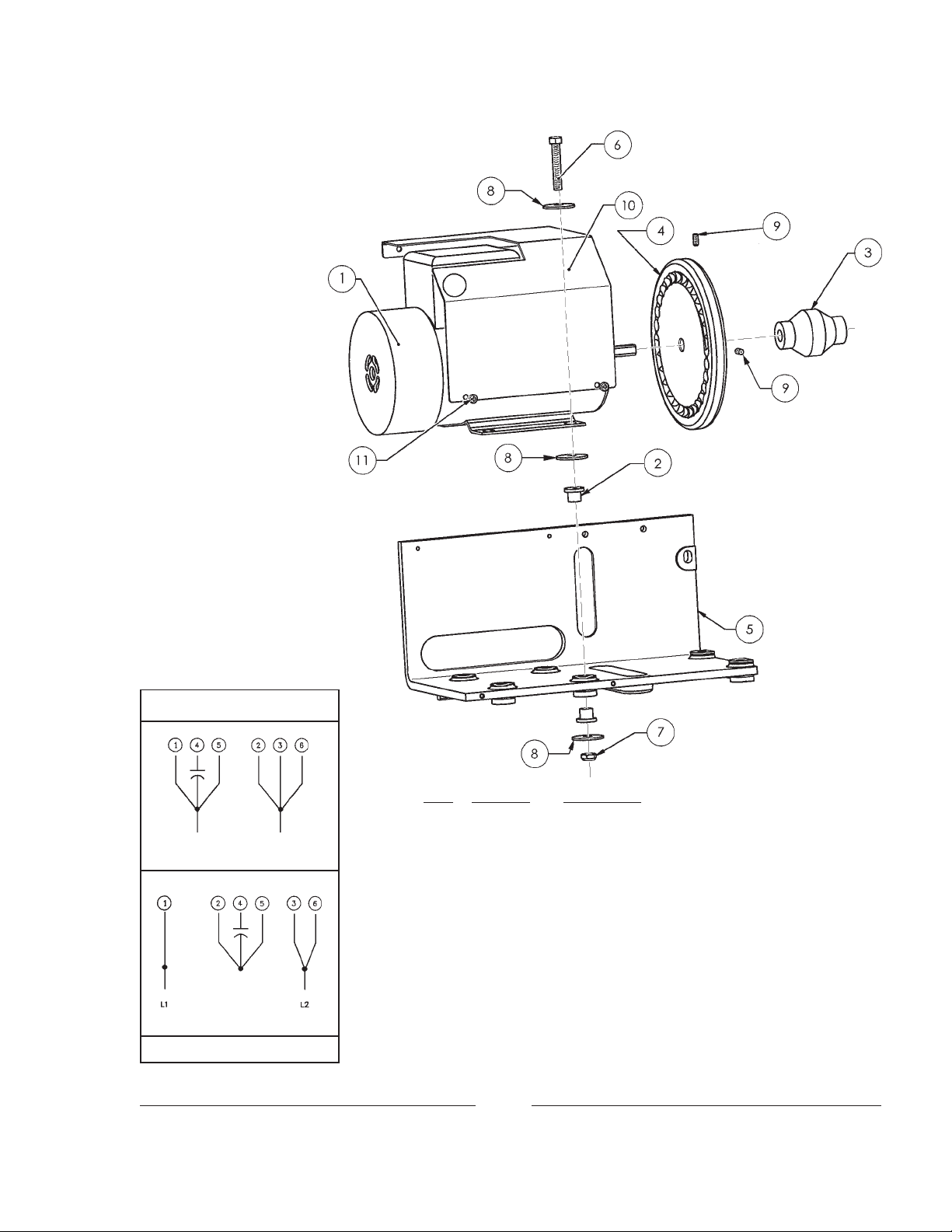
DRIVE MOTOR
Assembly No. 52-00204
MOTOR HOOK-UP
115 Volt
230 Volt
Fuse AC Input at 4 A.
Item Part No. Description
1 51-33003 Motor, 115/230 V.AC, 50/60 Hz.
2 51-07011 Grommet, Shock Mount (8 req’d.)
3 51-16003 Coupler
4 52-00344 Inching Wheel
5 52-00203 Motor Bracket
6 4251500 Screw, 1/4-20 x 1-1/2" (4 req’d.)
7 4258001 Nut, 1/4-20 FlexLock (4 req’d.)
8 4257102 Flatwasher, 1/4" SAE (12 req’d.)
9 408037C Set Screw, 8-32 x 3/8" (2 req’d.)
10 52-00464 Motor Guard
- 41-13004 Wire Clamp Bushing (not shown)
11 4060180 Screw, 6-32 x 3/16" Pan Head (4 req’d.)
Capacitor (7.5µf, 370 V.AC) included with Item 1 Motor
45
Page 51

G-4312 INTERMITTENT MOVEMENT
Assembly No. 52-60038
G-1830
P-2524
P-2524
NOTE: 52-00477 Stripper replaces P-1593
4060371 Screw replaces 4060250
on Apogee only
4060371
4060250
4060502
4060123
P-1938
52-00477
P-9711
P-4924
P-1593
4080374
G-2144
4050501
4058002
G-2330
P-1592
4080374
P-9118
P-4325
(Mounting Screws 4020253
not shown)
P-4384
P-9710
G-2178
51-48027
4040252
4040252
P-1599
G-1836
P-4398
4080623
G-1828
G-1828 Main Drive Gear (51-23014) P-9118 O-Ring (51-48020)
G-1830 Intermittent Flywheel & Gear (52-00061) P-9710 Starwheel Shaft (51-98197)
G-1836 Main Drive Shaft & Gear (51-52005) P-9711 Camshaft (51-98198)
G-2144 Outboard Bearing Arm (52-20078) 4020235 Screw, 2-56 x 1/2" (3 req’d.)
G-2178 Intermittent Case & Bearings (52-20094) 4040252 Oil Trap Screw (4 req’d.)
®
G-2330 Intermittent Sprocket, VKF
(21-59004) 4050501 Sprocket Retaining Screw
P-1592 Cover Gasket (51-22005) 4058002 Hex Nut, NyLock
P-1593 Intermittent Film Stripper (52-40027) 4060123 Collar Set Screw (2 req’d.)
P-1599 Oil Trap (52-20075) 4060250 Stripper Mounting Screw
P-1938 Starwheel Shaft Collar (51-11002) 4060371 Stripper Mounting Screw
P-2524 Flywheel Screw (51-51047; 2 req’d.) 4060502 Mounting Screw (2 req’d.)
P-4325 Cap (51-98176) 4080374 Fastening Screw (4 req’d.)
P-4384 Camshaft Spacer (51-70030) 4080623 Gear Retaining Screw
P-4398 Drive Gear Spacer (52-20169) 51-48027 O-Ring
P-4924 Intermittent Cover (52-00128) 52-00477 Film Stripper (Apogee only)
ORDER P-9710 & P-9711 IN MATCHED PAIRS
Rebuilt Simplex Intermittent Movements are available from the factory under a Repair/Exchange program.
Contact an authorized Strong International Dealer for details.
46
Page 52

INTERMITTENT PAD ARM
Assembly No. 52-00243
Item Part No. Description
1 52-00236 Base, Upper Guide
2 31-37001 Spring Pin, 3/4" x .1875"
3 52-00237 Intermittent Pad Arm
4 21-37009 Spring Pin, 1-1/2" x .1875"
5 51-98099 Shaft, Eccentric (P-3135)
6 4060253 Screw, 6-32 x 1/4"
7 52-00327 Intermittent Guide Roller
8 52-00019 Knob (P-3134)
9 4080120 Set Screw, 8-32 x 1/8"
10 52-00238 W eighted Roller
11 52-00280 Shaft “B”
Item Part No. Description
12 21-04003 Ball Bearing (2 req’d.)
13 408025D Screw, 8-32 x 1/4" Pan Head (4 req’d.)
14 52-00239 Intermittent Loop Chute
15 52-00241 Shaft “A” (2 req’d.)
16 52-00246 Pad Arm Pivot Shaft
17 21-49004 Pad Roller (2 req’d.)
18 51-58039 Expansion Spring (H-3719)
19 4110370 Screw, 1/4-20 x 3/4" Flat Head
20 81-56012 Spacer (SA-2442)
21 51-70007 Shim Washer (3 req’d.)
47
Page 53

UPPER/LOWER PAD ROLLER
Assembly No. 52-00247
Item Part No. Description
1 52-00244 Mounting Bracket
2 52-00246 Shaft, Pad Roller Arm
3 52-00245 Pad Roller Arm
4 51-98099 Shaft, Eccentric (P-3135), 2 req’d.
5 21-49004 Pad Roller (P-3085), 2 req’d.
6 52-00019 Knob (2 req’d.)
7 21-37009 Spring Pin, 1-1/4" x .1875"
8 4060253 Screw, 6-32 x 1/4" Socket Head (2 req’d.)
9 4080120 Set Screw, 8-32 x 1/8" (2 req’d.)
10 51-58039 Expansion Spring
11 51-37028 Spring Pin, 3/4" x .1875"
12 4250750 Screw, 1/4-20 x 3/4" Flat Socket Head
48
Page 54

49
OIL PUMP ASSEMBL Y
Page 55

OIL PUMP ASSEMBLY
Parts List
Item Part No. Description
1 51-23022* Oil Pump Driven Gear
2 52-00288 Pump Support Bracket
3 52-00001* Oil Pump Housing
4 51-39019* Oil Pump Gasket
5 51-98105* Oil Pump Drive Shaft
6 51-98016* Impellor Vane (2 req’d.)
7 51-58028* Compression Spring
8 4040751* Screw, 4-40 x 3/4" Socket Head
9 4040373* Screw, 4-40 x 3/8" Socket Head (3 req’d.)
10 52-20114* Pump Housing Cover
11 4110500 Screw, 10-32 x 1/2" Socket Head (2 req’d.)
12 51-07005 Compression Bushing (2 req’d.)
13 51-35007 Compression Nut (2 req’d.)
14 52-00360 Oil Intake Assembly, Apogee
15 52-00361 Oil Output Tube, Apogee
16 4110751 Mounting Screw, 10-24 x 3/4" Pan Head (2 req’d.)
- 51-48025 O-Ring, Oil Seal (2 req’d.)
* 52-60027 Pump Housing & Vane Assembly (G-1822)
50
Page 56

SHUTTER HOUSING
Assembly No. 52-00365
Shutter Cover 52-00374
Upper Mntg. Screw: 4080250
Lower Mntg. Screw: 4080375
Item Part No. Description
1 52-20129 Shutter Housing Casting
2 52-00161 Douser Plate
3 51-51030 Shoulder Screw, Douser Pivot
- 52-00376 Douser Linkage Rod (not shown)
4 4108002 Hexnut, 10-32 NyLock
51
Page 57

SHUTTER COMPENSA T OR MECHANISM
Assembly No. 52-00369
P-4390
P-10224
P-1472, P-1473, P-1474, P-1475:
Order 52-00368 Assembly
P-1487
P-1502
P-1486
P-1491
4100500
P-1484
52-00367
4080375
P-1476
4040252
P-1477
P-1475
P-1472
P-2013
4060502
P-1478
P-1473
P-1474
P-1826
4040373
P-1504
P-10224 Shutter
Blade & P-1826
Oil Collector are
not included with
52-00369; order
separately
4080623
P-1560
P-1488
P-1499-B
P-1470
P-1506
P-1492
P-2969 P-1482
4080374
P-2968
P-1489
P-1496
P-1494
4067000
4060751
P-1467
P-1480
P-2964
P-1490
52-00366
P-1495
P-1501
P-1497
P-4364
4100500
P-1483
P-1505
P-1481
P-3672
P-1466
P-1465
P-1485
P-2909
4100500
P-2849
4040373
P-4381
P-2907
P-6884
Page 58

SHUTTER COMPENSATOR ASSEMBLY
Parts List
P-1465 Compression Nut (51-35007) P-1501 Compression Spring, Guide Rod (51-58003)
P-1466 Compression Bushing (51-07005) P-1502 Pivot Screw, Adjusting Lever (52-20470)
P-1467 Roll Pin, Framing Rod (52-20105) P-1504 Bearing Retainer Plate, Outer (52-201 13)
P-1470 Spring Retaining Washer (51-70027) P-1505 Shutter Shaft (52-20122)*
P-1472 Bracket Casting, Shutter Adjusting P-1506 Snap Ring, W asher Retaining (11-48016)
Shaft (52-20038) P-1560 Bracket Gasket (51-22012)
P-1473 Pin, Shutter Adj. Gear (51-37002) P-1826 Oil Collector Casting (52-20126)
P-1474 Shutter Adjusting Gear (52-20107) P-2013 Retaining Ring, Rear Bearing (51-48012)
P-1475 Shutter Adjusting Shaft (52-20074) P-2849 Intermittent Oil Feed Tube (52-00042)
P-1476 Shaft Compression Spring (51-58026) P-2907 Spring Retaining Collar (52-20127)
P-1477 Retainer Plate, Stop Nut (52-40499) P-2909 Compression Spring (51-58019)
P-1478 Stop Nut, Adjusting Shaft (52-20108) P-2964 Loading Spring, Shutter Shaft (51-58024)
P-1480 Framing Rod Roller (52-20106) P-2968 Spring Retaining Washer (51-70025)
P-1481 Shaft Ball Bearing, Rear (51-04014) P-2969 Retaining Ring, Front Bearing (51-48013)
P-1482 Shaft Ball Bearing, Front (51-04008) P-3672 Oil Seal, Shaft Bracket (51-36003)
P-1483 Spline Ball Bearing (51-04006) P-4364 Flanged Spline (52-20251)*
P-1484 Shutter Shaft Mounting Bracket P-4381 Collar Retaining Ring (51-37012)
Casting (52-00078) P-4390 O-Ring (51-48005)
P-1485 Bearing Retaining Plate (52-00066) P-6884 Washer, .625" I.D. x .75" O.D. (52-00390)
P-1486 Framing Rod Screw Gear (52-20109) P-10224 Shutter Casting (52-20791, as shown)
P-1487 Adjusting Lever (52-00041) Three-Bladed Shutter: P-2885 (52-00140)
P-1488 Slide Rod, Adjusting Spline Support 4040252 Fastening Screw, 4-40 x 1/4" (2 req’d.)
Bracket (52-20110) 4040373 Fastening Screw, 4-40 x 3/8" (7 req’d.)
P-1489 Shutter Shaft Driven Gear (51-23020) 4060502 Guide Rod Retaining Screw , 6-32 x 1/2"
P-1490 Adjusting Spline Support (52-00029) 4060751 Clamping Screw, Bearing; 6-32 x 3/4"
P-1491 Rod Compression Spring (51-58027) 4067000 Lockwasher, Clamping Screw
P-1492 Framing Rod Guide Screw (52-02448) 4080375 Knob Fastening Screw, 8-32 x 3/8
P-1494 Shutter Shaft Spacer (51-98104) 4080374 Slide Rod Fastening Screw, 8-32 x 3/8"
P-1495 Pin, Driving Flange (52-20111)* 4080623 Clamping Screw, 8-32 x 5/8" (2 req’d.)
P-1496 Pin, Adjusting Lever 51-37010) 4100500 Fastening Screw, 10-32 x 1/2" (6 req’d.)
P-1497 Clamping Nut (52-20458; 2 req’d.) 52-00366 Framing Rod
P-1499-B Guide Rod, Support Brkt. (52-20112) 52-00367 Shutter Adjusting Knob
* Order G-4364 Spline & Shaft Assembly (51-52019)
53
Page 59

G-9727 PICTURE CHANGEOVER DEVICE
Assembly No. 52-60325 (1 10 V.AC)
Assembly No. 52-60326 (220 V .AC)
54
Green - Ground
White - Common
Black - Open
Red - Close
Page 60

G-9727 PICTURE CHANGEOVER
Parts List
Item Part No. Description
1 52-40233 Base Plate (P-7926)
2 51-98254 Clevis Pin, 1/8" Diameter (P-7966)
3 01704000 Hitch Pin, 1/16" Diameter
4 4047101 Flatwasher, #4
5 51-98090 Bell Crank (P-7892)
6 52-20677 Pivot, Bell Crank (P-7923)
7 51-98254 Clevis Pin, 1/8" Diameter (P-7966)
8 52-40231 Bracket, Changeover Body (P-7919)
9 51-55005 Solenoid, 1 15 V.AC Coil (with 52-60325)
- 51-55006 Solenoid, 230 V.AC Coil (with 52-60326)
10 52-40231 Bracket, Changeover Body (P-7919)
11 4060372 Screw, 6-32 x 3/8" Socket Head
12 52-40232 Connector (P-7925)
13 52-20676 Push Rod (P-7922)
14 51-58058 Spring (P-7920)
15 52-40231 Bracket, Changeover Body (P-7919)
16 4040120 Screw, 4-40 x 1/8" Pan Head
17 4040250 Screw, 4-40 x 1/4" Pan Head
18 51-98254 Clevis Pin, 1/8" Diameter (P-7966)
19 51-55005 Solenoid, 110 V.AC Coil (with 52-60235)
-- 51-55006 Solenoid, 220 V.AC Coil (with 52-60236)
20 52-40235 Cover (P-7924)
21 4060250 Screw, 6-32 x 1/4" Pan Head
52-60235 Picture Changeover Assembly , Complete (1 15 V.AC)
52-60236 Picture Changeover Assembly , Complete (230 V.AC)
NOT SHOWN
52-00376 Linkage Rod, Bell Crank to Douser Plate
41-10030 Nylon Cable Clamp, 3/8"
41-13008 Cable Connector, 90°
51-71007 Cable, (4) Conductor, Type SO (2 feet required)
Douser Plate 52-00161 (see Page 51) not included with G-9727 Changeover and must be ordered separately.
55
Page 61

APOGEE SOUND READER
Assembly No. 52-00297
Item Part No. Description
1 52-00290 Sound Reader Base, Machined
- 4100870 Mounting Screw (to Main Frame), 10-32 x 7/8" Socket Head (3 req’d.)
2 51-04006 Ball Bearing (P-1483)
3 52-00289 Impedance Drum & Shaft
4 52-00276 Roller Mounting Bracket
5 4080502 Screw, 8-32 x 1/2" Socket Head
6 52-00280 Roller Shaft
7 21-04003 Ball Bearing
8 52-20428 Guide Roller (P-4672)
9 408025D Screw, 8-32 x 1/4" Pan Head
10 410050A Screw, 10-32 x 1/2" Flat Socket Head
11 51-58047* Wave Spring W asher (P-1653)
12 52-00295* Flywheel Spacer
13 52-00294* Flywheel
14 51-51013* Flywheel Mounting Screw, 1/4-20 x 3/4" Hex Head, Left-Hand Thread
* not included with 52-00297; order separately
56
Page 62

SOUND READER COMPONENTS
Item Part No. Description
1 5198413-1 Reader Plate Assembly
2 5198413-2 Digital (Dolby®)Pick-Up Assembly
3 5198413-3 Analog Pick-Up Assembly
4 5198413-4 Outer L.E.D. Illuminator (Digital)
5 5198413-5 Inner L.E.D. Illuminator (Analog)
6 5198413-6 Standoff Block
7 5198413-7 Stud Plate, Illuminators
NOT SHOWN
4080502 Screw, 8-32 x 1/2" Socket Head
410050A Screw, 10-32 x 1/2" Flat Socket Head
51-35003 FlexLock Hexnut, 1/4-28 (P-1471)
51-98415 L.E.D. Power Supply, LS-40
57
Page 63

 Loading...