

Page 1
4190-9007 Remote Printer
Installation Instructions
Cautions and Warnings
DO NOT INSTALL ANY SIMPLEX PRODUCT THAT APPEARS
DAMAGED. Upon unpacking your Simplex product, inspect the contents of the
carton for shipping damage. If damage is apparent, immediately file a claim
with the carrier and notify Simplex.
ELECTRICAL HAZARD - Disconnect electrical power when making any
internal adjustments or repairs. Servicing should be performed by qualified
Simplex Representatives.
STATIC HAZARD - Static electricity can damage components. Therefore,
handle as follows:
1. Ground yourself before opening or installing components (use the 553-484
Static Control Kit).
2. Keep uninstalled component wrapped in anti-static material at all times.
RADIO FREQUENCY ENERGY - This equipment has been tested and found
to comply with the limits for a Class B digital device, pursuant to Part 15 of the
FCC rules. These limits are designed to provide reasonable protection against
harmful interference when the equipment is operated in a commercial
environment. This equipment generates, uses, and can radiate radio frequency
energy and, if not installed and used in accordance with the instruction manual,
may cause harmful interference to radio communications. Operation of this
equipment in a residential area may cause interference in which case the user
will be required to correct the interference at his own expense.
Overview
In This Publication
This document describes the installation procedure for the 4190-9007 Remote
Printer. Consult the User’s Guide supplied with your printer for a detailed
description of mechanical setup, features and operating principles.
The 4190-9007 Remote Printer interfaces with Simplex Fire Alarm and Nurse
Call systems. The printer provides hard copy of status reports for these systems:
• Fire Alarm
- 2120 Multiplex - 4120 Network
- 4010 - 4120 GCC
- 4020 - 4120 NPU
- 4100+
• 5001 Nurse Call
The following topics are covered in this publication.
Topic
Control Panel DIP Switches 2
Serial Interface DIP Switches 3
Printer Connections 6
Connecting to Fire Alarm Systems 7
4010 Front Panel Programming for an RS-232 Port 9
Connecting to 5001 Nurse Call 12
Control Panel 13
Page Number
2000 Simplex Time Recorder Co., Westminster, MA 01441-0001 USA
All specifications and other information shown were current as of publication, and are subject to change without notice.
574-124
Rev. B
Page 2
Control Panel DIP Switches
Overview
Setting DIP Switch 1
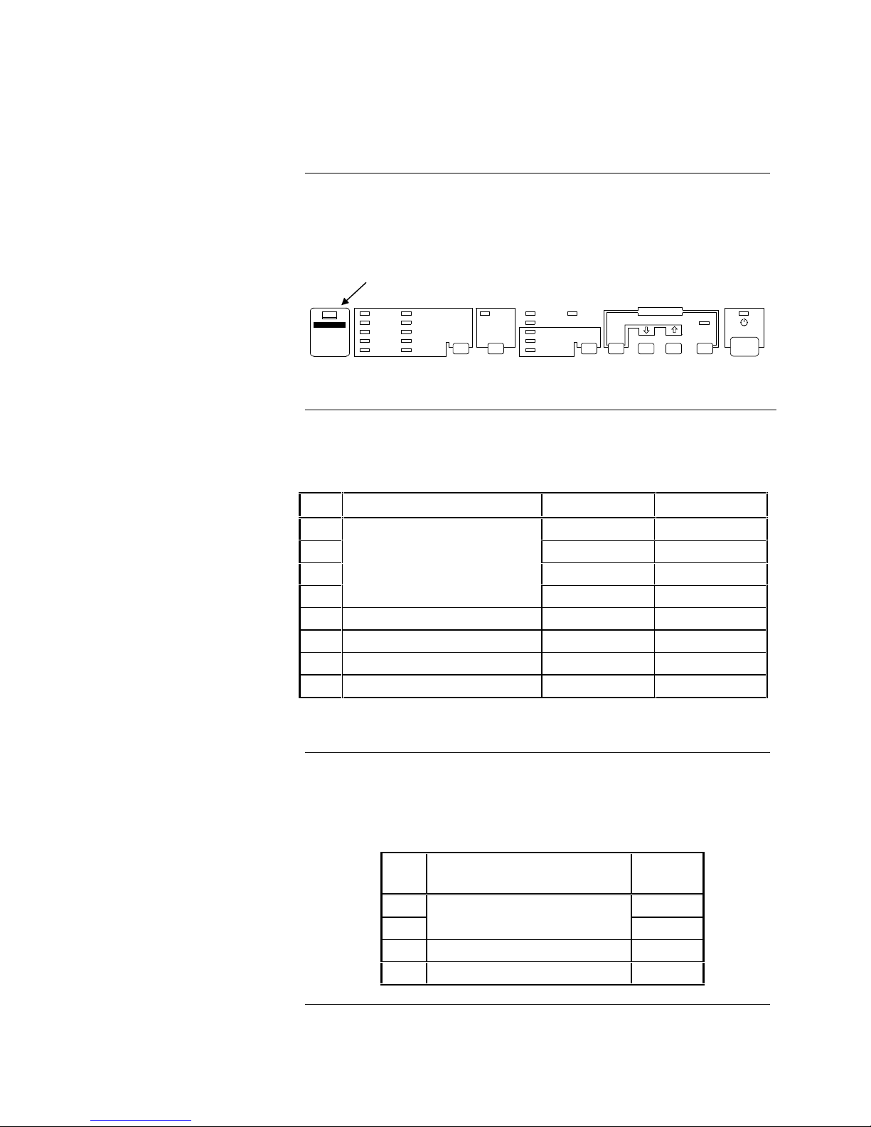
The 4190-9007 printer is equipped with two DIP switches that control the
printer’s features. The DIP switches are located behind the switch cover on the
control panel (see Figure 1). Tables 1 and 2 define the settings for DIP Switch 1
and 2.
DIP switch cover
DRAFT
COURIER
ROMAN
SANS SERIF
PRESTIGE
SCRIPT
SCRIPT C
OPERATOR
OPERATOR-S
OCR-B
FONT CONDENSED
MULTI-PART
PAPER-OUT
BIN 1
BIN 2
TEAR OFF
DATA
FONT FONT
BUFFER CLEAR
MICRO FEED
LOAD/EJECTLF/LL PAUSE
OPERATE
Figure 1. Location of DIP Switch Cover
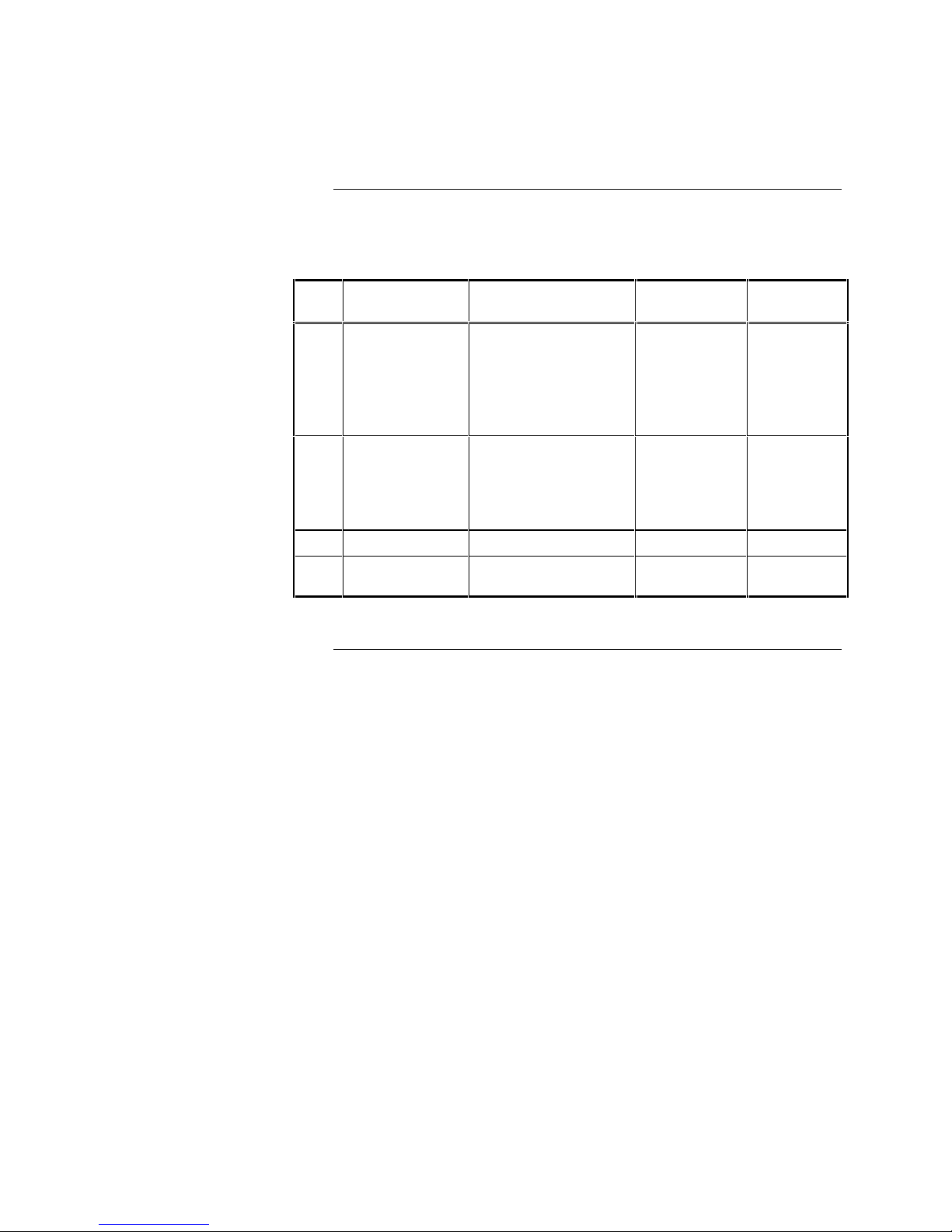
DIP Switch 1 has eight switches. Table 1 describes the settings for DIP Switch 1.
Table 1. DIP Switch 1
SW Description ON OFF
1-1 ON*
1-2 ON*
1-3 ON*
1-4
USA
OFF*
1-5 Print Direction Unidirectional Bidirectional*
1-6 Printer Mode** IBM emulation ESC/P 2*
1-7 Input buffer None 8KB*
1-8 1-inch skip-over-perforation ON OFF*
Setting DIP Switch 2
Notes: * Indicates S implex settings.
** SW 1-6 functions only on the European version of this printer.
DIP Switch 2 has four switches. Set these switches to the ON position.
Table 2 describes the settings for DIP Switch 2.
Table 2. DIP Switch 2
SW Description
2-1 ON
2-2
Page length
(for continuous paper)
Simplex
Setting
ON
2-3 Tear Off ON
2-4 Auto line feed ON
2
Page 3
DIP
Serial Interface DIP Switches
Introduction
The serial interface card enables communication between the 4190-9007 Remote
Printer and a host computer (see Figure 3 for the location of the serial interface
compartment).
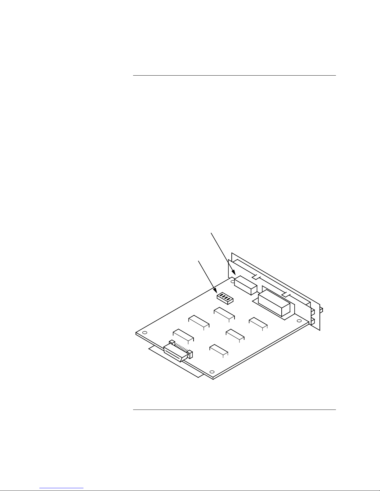
The serial interface card has two sets of DIP switches (see Figure 2). You
control interface operations by adjusting the switch settings.
Notes:
• You can access DIP Switch 1 and adjust settings as needed even after
installing the interface card.
• DIP Switch 2 is not readily accessible after installation. Therefore, make
any necessary adjustments to DIP Switch 2 before installing the serial
interface card.
This section describes the DIP switch settings for operation with compatible Fire
Alarm systems. Refer to the Serial Interfac e Card manual (provided with the
serial interface card) for detailed information on serial interface card installation.
SWITCH
1
DIP
SWITCH
2
Figure 2. Serial Interface Card DIP Switches
Continued on next page
3
Page 4
Serial Interface DIP Switches, Continued
Serial Interface
DIP Switch 1
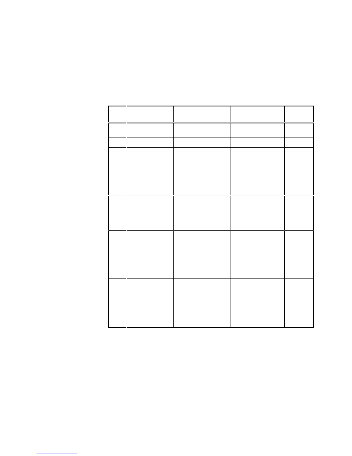
Table 3 defines the serial interface settings for DIP Switch 1.
Table 3. DIP Switch 1 Settings
SW Function ON OFF
1-1
1-2 Word Length 8-bit 7-bit
1-3 Parity Check 1
1-4 Parity Check 2
1-5 Baud Rate 1
1-6 Baud Rate 2 N/A
Interface Card
Enable/Disable
Enable Disable
ON
For both even
parity (4020,
4100+, 4120), and
for odd parity
(4120 GCC,
4120 NPU)
ON
For even parity
(4020, 4100+,
4120)
ON
for both 1200 baud
(2120, 4020,
4100+, 4120), and
9600 baud (4010,
4120 GCC,
4120 NPU)
OFF
No parity
(2120, 4010)
OFF
For odd or no
parity (2120, 4010
4120 GCC,
4120 NPU)
N/A
OFF
for both 1200 baud
(2120, 4020,
4100+, 4120), and
for 9600 baud
(4010, 4120 GCC,
4120 NPU)
Simplex
Setting
ON
ON
ON
ON
ON
OFF
Note: Units must be set for NO parity at 1200 baud.
Continued on next page
4
Page 5
Serial Interface DIP Switches, Continued
Serial Interface Card
DIP Switch 2
Table 4 defines the settings for DIP Switch 2.
Table 4. DIP Switch 2 Settings
SW Function ON OFF
ON
for both 1200 baud
2-1 Baud Rate 3
2-2 Baud Rate 4
2-3 Handshake DTR X-on/X-off
2-4
RS-232D/
Current Loop
Note: Unit to be set for 1200 baud.
(2120, 4020, 4100+,
4120), and 9600
baud (4010, 4120
GCC, 4120 NPU)
ON
for 9600 baud rate
(4010, 4120 GCC,
4120 NPU)
RS-232D Current Loop
N/A
OFF
for 1200
baud rate
(2120, 4020,
4100+, 4120)
Simplex
Setting
ON
OFF
ON
ON
5
Page 6

Printer Connections
Overview
Connector Ports
The following sections illustrate the connections between the 4190-9007 Remote
Printer and the various host systems (Fire Alarm or Nurse Call) with which it is
compatible.
Use the port on the serial interface card for connections between the printer and
host systems. The serial interface compartment is located directly above the
parallel interface port on the rear panel of the printer (see Figure 3).
Note: When connecting to a 4120 GCC system you have the option of using
the parallel port. If using this option, refer to the section “Parallel
Interface Option with the 4120 GCC.”
SERIAL INTERFACE
COMPARTMENT
RS-232 CONNECTOR
WITH INTERNAL SUPPRESSION
PARALLEL
733-937 HARNESS
(SUPPLIED)
INTERFACE
Figure 3. Connecting to the Printer
6
Page 7

TO 4190-9007 PRINTER
(
)
→
(
)
Connecting to Fire Alarm Systems
y
g
Connecting to 4020, 4100+,
4120 Network, 4120 GCC or
4120 NPU Systems
3 or 8 4 or 9 5 or 10 TB1
BLACK
(RECEIVE)
WHITE
(HAND
RED
(NOT USED)
TO 4190-9007 PRINTER
SHAKE)
32
Use the 733-937 harness provided with the Simplex shipment (see Figure 3).
The harness is equipped with an RS-232 connector with internal suppression.
Follow Steps 1 through 3 when using the serial interface port to connect to the
host system.
1. Connect the harness to the serial interface port of the printer.
2. 4020 FACP Refer to Figure 4 to complete the connection to the RS-232
card.
3. 4100+ System, 4120 Network, 4120 GCC, and 4120 NPU system Refer to
Figure 5 to complete the connection to a COM port.
GREEN
(COMMON)
720
4020, 4100+, OR 4120 NETWORK → RS-232 CARD
RED
NOT USED
4120 GCC OR 4120 NPU
275
BLK GRN WHT
RECEIVE
BLK GRN WHT
37202
COM PORT
COMMON
HANDSHAKE
733-937
HARNESS
FURNISHED
ure 4. Connecting to the 4020 FACP
Fi
Parallel Interface Option with
the 4120 GCC
Figure 5. Connecting to 4100+, 4120 Network,
4120 GCC, or 4120 NPU S
stems
Use the standard parallel cable supplied with the printer (the 733-937 harness is
not used with the parallel interface). Follow these steps.
1. Disable the serial interface as follows:
a. Loosen the two screws that hold the serial interface card in place.
b. Pull the card out of the unit.
2. Connect the cable from the parallel port of the printer to the parallel port of
the host system.
Note: The parallel cable provides a maximum distance of 6 feet from the
printer to host.
Continued on next page
7
Page 8

Connecting to Fire Alarm Systems, Continued
Connecting to 2120 Multiplex
System and 4010 FACP
Use the 733-937 harness provided with the Simplex shipment (see Figure 3).
The harness is equipped with an RS-232 connector with internal suppression.
Follow these steps to connect the printer to the 2120 Multiplex or 4010 FACP.
• Connect the harness to the serial interface port of the printer.
• Refer to Figure 6 to complete the connection to the 2120 BMUX.
• Refer to Figure 7 to complete the connection to the 4010 FACP.
2120 BMUX (RS-232 CONNECTOR)
3720
COMMON
RED
(NOT USED)
RECEIVE
BLK GRN WHT
37202
HANDSHAKE
733-937
HARNESS
(FURNISHED)
Note Refer to the “4010 Front Panel
Programming for an RS-232
Printer Port” section of this
document if you are wiring the
printer to a 4010 FACP.
(NOT USED)
TO 4190-9007 PRINTER
Figure 6. Connecting to 2120 Multiplex System
123456
RED
BLK
31
TO 4190-9007 PRINTER
720
GRN
WHTBLU
733-937
HARNESS
(FUNISHED)
Figure 7. Connecting to a 4010 FACP
8
Page 9

4010 Front Panel Programming for an RS-232 Port
Introduction
Adding an RS-232 Card
This section describes programming a printer port on a 4010 RS-232 card from
the front panel of the 4010 FACP.
Note: Login to the system at access level 4 before attempting to
program the port.
This section describes adding the RS-232 card to the 4010 job.
1. Press <MENU>.
2. Press <NEXT> or <PREVIOUS> until [PROGRAMMING] is displayed
and then press <ENTER>. The following warning appears, indicating that
the 4010 is no longer in the Fire Alarm Operation mode.
Please Wait . . .
Fire Alarm Operation Suspended
3. Press <ENTER> to co ntinue.
4. Press <NEXT> or <PREVIOUS> until <CONFIGURE CARDS> is
displayed and then press <ENTER>.
5. Press <NEXT> or <PREVIOUS> until <ADD A 4010 CARD> is
displayed and then press <ENTER>.
6. Press <NEXT> or <PREVIOUS> until <RS232> is displayed and then
press <ENTER>. P ress <ENTER> again to confirm that you want to add
an RS-232 card. A message appears indicating that the system is
configuring the card.
Configuring RS-232 Port
Settings
Press the <EXIT> key once to move back one menu level and then continue
below with Step 5 in the next section.
Use the following steps to configure the printer settings (baud rate, etc) for the
RS-232 port to which the printer is attached. Before beginning, ensure you
know the hardware settings enabled on the printer (i.e., baud rate set on printer
itself).
1. Press <MENU>.
2. Press <NEXT> or <PREVIOUS> until [PROGRAMMING] is displayed
and then press <ENTER>. A warning appears, indicating that the 4010 is
no longer in the Fire Alarm Operation mode.
Please Wait . . .
Fire Alarm Operation Suspended
3. Press <ENTER> to continue.
Continued on next page
9
Page 10

4010 Front Panel Programming for an RS-232 Port, Continued
Configuring RS-232 Port
Settings (continued)
4. Press <NEXT> or <PREVIOUS> until <CONFIGURE CARDS> is
displayed and then press <ENTER>.
5. Press <NEXT> or <PREVIOUS> until <MODIFY 4010 CARD> is
displayed and then press <ENTER>.
6. Press <NEXT> or <PREVIOUS> until the display reads
<CARD TYPE=RS232 CARD> and then press <ENTER>.
7. Press <NEXT> or <PREVIOUS> to select either <PORT A> or
<PORT B> and then press <ENTER>.
A display similar to the following appears, allowing you to set the
communication settings for the port.
<ENTER> to ACCEPT <ARROW KEYS> to Change
Port[PRT80U] BAUD 9600 Parity None
8. Use the arrow keys to move the bracket to the [PORT] Parameter. Use the
<NEXT> and <PREVIOUS> keys to select a choice for this parameter.
Note that you must have an 80-column printer to print 4010 reports.
Choices are as follows:
• PRT80U. Unsupervised, 80-column printer
• Unused.
• PRT40S. Supervised, 40-column printer
• PRT40U. Unsupervised, 40-column printer
• PRT80S. Supervised, 80-column printer
9. Use the arrow keys to move the bracket to the [BAUD] Parameter. Use the
<NEXT> and <PREVIOUS> keys to select a choice for this parameter.
Choices are as follows:
• 1200
• 2400
• 4800
• 9600
• 19200
• 38400
10. Use the arrow keys to move the bracket to the [PARITY] parameter. Use
the <NEXT> and <PREVIOUS> keys to select a choice for this parameter.
Choices are as follows:
• None
• Even
• Odd
11. Press <ENTER>. A display similar to the following appears, allowing you
to select which events are routed to the printer
Press <ENTER> to Send ALL Events to Port
Press <NEXT> to Select Events
Continued on next page
10
Page 11

4010 Front Panel Programming for an RS-232 Port, Continued
Configuring RS-232 Port
Settings (continued)
12. Choose which events are sent to the printer when they occur, as follows:
Send All Events to Printer. Press <ENTER> to send all of the events
listed in Table 5 (below) to the printer. After you press <ENTER>, the
display indicates that the option is updated and exits to the <MODIFY 4010
CARD> selection in the Programming menu. Press the <EXIT> key twice.
A message appears, i ndicating that the c onfiguration has changed. Move to
the <SAVE CFIG> choice and press <ENTER>. Another message
appears, as ki ng you t o confirm the Save op eration. Press <ENTER> to
save the new CFIG.
Route Specific Events to Printer. Press <NEXT> to individually select
which events are sent to the printer when they occur. A series of prompts,
each of which is listed in Table 5, appears. For each prompt, press the
<NEXT> and <PREVIOUS> keys to toggle between the YES and NO
selections. When the setting is correct, press <ENTER>. After the last
prompt appears, the system prompts you to <PRESS ENTER TO SAVE
OR EXIT TO CANCEL>. After you press <ENTER>, the display
indicates that the option is updated and exits to the <MODIFY 4010
CARD> selection in the Programming menu. Press the <EXIT> key twice.
A message appears, i ndicating that the c onfiguration has changed. Move to
the <SAVE CFIG> choice and press <ENTER>. Another message
appears, as ki ng you t o confirm the Save op eration. Press <ENTER> to
save the new CFIG.
Table 5. Routing Specific Events
Prompt
Send Fire Events to Port? Yes Routes information on all fire alarms to the printer.
Send Supervisory Events to Port? Yes
Send Trouble Events to Port? Yes Routes information on all trouble events to the printer.
Send Reset/Silence to Port? Yes
Send Test Events to Port? Yes Routes all Walktest events to the printer.
Send Control Events to Port? No
Send Utility Events to Port? No
Send Pseudo Events to Port? No
Send CCE Print Events to Port? Yes Routes Custom Control Print statements to the printer.
Send Reports to Port? Yes Sends reports to the printer.
Default
Setting
Explanation
Routes information on all supervisory events to the
printer.
Routes information to the printer each time a system
reset or signal silence occurs.
Routes information to the printer each time a control
circuit (signals/aux relays) turns ON or OFF.
Routes information to the printer each time the
ON/OFF state of a utility point changes.
Routes information to the printer each time the
ON/OFF state of a pseudo point changes.
11
Page 12

)
Connecting to 5001 Nurse Call
Connecting to 5001 Nurse Call
Male and female DB25 connectors (with pigtails) are provided with the printer
port.
Follow Steps 1 and 2 to make the connection between the printer and the
5001 Nurse Call system:
1. Connect the male DB25 connector to the printer.
2. Connect the female DB25 connector to the serial port
of the 5001 CPU.
Note: The 733-937 harness is not used when connecting to the 5001 Nurse
Call system. Figure 8 illustrates the connection between the 4190-9007
printer and the 5001 CPU.
5001 CPU (DB25 SERIAL PRINTER PORT
267
15
SHIELD
5-CONDUCTOR
CABLE W/SHIELD
(#18 AWG)*
RED
WHT GRN BLK
SHIELD
RECEIVE
Figure 8. Connecting to 5001 Nurse Call
HANDSHAKE
SEND
DATA
3671
* MAXIMUM DISTANCE BEWEEN
PRINTER AND 5001 CPU IS 100 FEET
11 20
TO 4190-9007 PRINTER
12
COMMON
Page 13

Control Panel
Control Panel Illustration
DRAFT
COURIER
ROMAN
SANS SERIF
PRESTIGE
Control Panel Buttons
SCRIPT
SCRIPT C
OPERATOR
OPERATOR-S
OCR-B
Figure 9 illustrates the front panel of the printer. Refer to the indicator lights on
the control panel for current status of the printer. Use the buttons to control
printer settings.
BUFFER CLEAR
MICRO FEED
LOAD/EJECTLF/LL PAUSE
OPERATE
FONT CONDENSED
MULTI-PART
PAPER-OUT
BIN 1
BIN 2
TEAR OFF
DATA
ALT
Figure 9. Control Panel Buttons and Lights
The following sections detail the functions of the buttons and lights that are
useful when setting up the printer for operation.
Table 6 identifies the functions of panel buttons.
Table 6. Using the Control Panel Buttons
If you want to… Then:
Temporarily stop printing Press the PAUSE button
Resume printing Press PAUSE again
Load paper manually—single sheet
or continuous (Printer normally
loads paper automatically)
Eject single-sheet paper already in
the loading position
Press the LOAD/EJECT
button
Feed continuous paper backward
from the loading or tear-off position
to the standby position
Feed paper forward one line
Load a single sheet of paper from
the cut-sheet feeder
Feed continuos paper from standby
position to loading position
Eject a single sheet of paper
Advance continuous paper to top of
next page
13
Press the LF/FF
(line feed/form feed) button
Hold down the LF/FF button
Continued on next page
Page 14

Control Panel, Continued
Control Panel Lights
Additional Information
Table 7 describes the messages indicated when panel lights are ON.
Table 7. Control Panel Light Messages
Light Color Message
Operate Green Operate switch is on and power is supplied.
Printer is not ready to print data.
Pause Orange
Paper Out Red Printer is out of paper.
Consult printer manual for details on printer set-up, control logic, and paper
loading.
Operator has pressed PAUSE button to
prevent printing.
574-124
Rev. B
 Loading...