

Simplex 4100U,4100ES Application Manual
Smoke Management
Application Guide
574-465
Rev. D


Acknowledgements
Acknowledgements
Tyco Safety Products – Westminster, gratefully acknowledges the contributions of the following
organizations to this publication:
• American Society of Heating, Refrigerating and Air-Conditioning Engineers, Inc.
(ASHRAE), Atlanta, GA.
• Andover Controls Corporation, Andover, MA.
• Center for Fire Research, National Engineering Laboratory, National Bureau of Standards,
U.S. Department of Commerce, Washington, DC.
• Integrated Systems, Inc., Brunswick, MD.
• National Fire Protection Association, Inc. (NFPA), Quincy, MA.
• U.S. Veterans Administration, Office of Construction, Washington, DC.

Cautions and Warnings
Cautions and
Warnings
READ AND SAVE THESE INSTRUCTIONS- Follow the instructions in this installation
manual. These instructions must be followed to avoid damage to this product and associated
equipment. Product operation and reliability depend upon proper installation.
DO NOT INSTALL ANY PRODUCT THAT APPEARS DAMAGED.
Upon unpacking your product, inspect the contents of the carton for shipping damage.
If damage is apparent, immediately file a claim with the carrier and notify your distributor.
ELECTRICAL HAZARD - Disconnect electrical field power when making any internal
adjustments or repairs. All repairs should be performed by a representative or authorized agent of
your local Simplex
®
product supplier.
STATIC HAZARD - Static electricity can damage components. Therefore, handle as follows:
1. Ground yourself before opening or installing components.
2. Prior to installation, keep components wrapped in anti-static material at all times.
FCC RULES AND REGULATIONS – PART 15 - This equipment has been tested and found to
comply with the limits for a Class A digital device, pursuant to part 15 of the FCC Rules. These
limits are designed to provide reasonable protection against harmful interference when the
equipment is operated in a commercial environment. This equipment generates, uses, and can
radiate radio frequency energy and, if not installed and used in accordance with the instruction
manual, may cause harmful interference to radio communications. Operation of this equipment in
a residential area is likely to cause harmful interference in which case the user will be required to
correct the interference at his own expense.

Copyrights, Trademarks, and Patent Data
Copyrights
Trademarks
Patent Data
©2004, 2011 SimplexGrinnell LP. All rights reserved.
Specifications and other information shown were current as of publication and are subject to
change without notice.
To further the science of Smoke Management, Tyco Safet y Pro d uct s hereby grants permission to
reproduce or transmit this reference document in any form or by any means, electronic or
mechanical, for the purpose of obtaining information on the science of Smoke Management.
We retain the rights of our respective trademarks.
Simplex, the Simplex logo, TrueSite, TrueAlarm, and IDNet are either trademarks or registered
trademarks of Tyco International Ltd and its affiliates and are used under license. NFPA 72 and
National Fire Alarm Code are registered trademarks of the National Fire Protection Association
(NFPA).
Walk Test™ is protected by US Patent No. 4,725,818 .
MAPNET II® addressable communications is protected by U.S. Patent No. 4,796,025.
IDNet™ is patent pending.
®
TrueAlarm
TrueAlarm
Windows
VESDA Scanner™ and MiniVESDA™-50 are trademarks and the name VESDA
VESDA
Analog Detection is protected by U.S. Patent No. 5,155,468.
®
Detector Base is protected by U.S. Patent No. 5,173,6 83.
®
is a registered trademark of the Microsoft Corporation.
®
E70-D are registered trademarks of Vision Systems.
®
and
All other logos are trademarks or registered trademarks of their respective com panies.


Table of Contents
Chapter 1 How Smoke Control Systems Work 1-1
Purpose ................................................................................................................... 1-1
Introduction .............................................................................................................. 1-1
In this Chapter ......................................................................................................... 1-1
Introduction .................................................................................................................. 1-2
Design Parameters .................................................................................................. 1-2
Design Concepts ..................................................................................................... 1-2
Controlling Smoke Movement ..................................................................................... 1-3
Basic Concept .......................................................................................................... 1-3
Creating Smoke Zones ............................................................................................ 1-5
Causes of Smoke Movement .................................................................................. 1-6
Managing Smoke Movement ................................................................................... 1-7
Principles of Smoke Control Systems ......................................................................... 1-8
System Types .......................................................................................................... 1-8
Maintaining System Integrity ................................................................................... 1-8
Smoke Control and Fire Control System Differences .................................................. 1-9
Separate System for Separate Goals ...................................................................... 1-9
Designing a Smoke Control System .......................................................................... 1-10
Basic Goal ............................................................................................................. 1-10
How to Begin ......................................................................................................... 1-10
Engineering Responsibility .................................................................................... 1-10
Creating the Zone-By-Zone Smoke Control Plan .................................................. 1-10
Determining the Smoke Containment Pressure .................................................... 1-11
Separating Smoke Zones Properly ........................................................................ 1-11
Selecting the Proper Fans and Duct Work ............................................................ 1-11
Choosing the Proper Dampers .............................................................................. 1-12
Placing Air Inlets and Outlets ................................................................................ 1-12
Designing a Dedicated Smoke Control System ........................................................ 1-13
Introduction ............................................................................................................ 1-13
About Stairtowers .................................................................................................. 1-13
Designing the Ideal Stairtower System .................................................................. 1-14
Ensuring Doors Can Open .................................................................................... 1-14
Controlling Pressure in a Stairtower ...................................................................... 1-15
Elevator Smoke Control ......................................................................................... 1-18
Detecting Smoke ....................................................................................................... 1-19
Introduction ............................................................................................................ 1-19
Configuring and Monitoring a Smoke Control System .......................................... 1-19
Firefighter Smoke Control Station (FSCS) ............................................................ 1-19
Testing the System ................................................................................................ 1-20
Related Documentation ......................................................................................... 1-20
Chapter 2 Smoke Control Design Parameters 2-1
Introduction .............................................................................................................. 2-1
In this Chapter ......................................................................................................... 2-1
iii

System Requirements ................................................................................................. 2-2
General Requirements ............................................................................................. 2-2
Agency Requirements ............................................................................................. 2-2
System Design Parameters ......................................................................................... 2-3
Verifying System Integrity During Non-Emergency Conditions ............................... 2-3
Weekly Self-Test ...................................................................................................... 2-3
Verifying System Integrity During Emergency Conditions ....................................... 2-3
Automatic Activation ................................................................................................ 2-3
Subsequent Automatic Activation ............................................................................ 2-4
Automatic Activation By a Manual Pull Box ............................................................. 2-4
Manual Operation .................................................................................................... 2-4
Automatic Override of Manual Activation ................................................................ 2-4
Chapter 3 Smoke Control System Components 3-1
Introduction .............................................................................................................. 3-1
In this Chapter ......................................................................................................... 3-1
Smoke Control System ................................................................................................ 3-2
Smoke Control System ............................................................................................ 3-2
4100U/4100ES Panels ............................................................................................... 3-3
4100U/4100ES Panel ............................................................................................. 3-3
4190 TrueSite Workstation and 24 Point I/O Graphic Interface .................................. 3-4
4190 TrueSite Workstation (TSW) ........................................................................... 3-4
24-Point I/O Graphic Interface (4100-7401) ............................................................ 3-4
Optional and Peripheral System Components ............................................................ 3-5
Optional System Components ................................................................................. 3-5
Peripheral Components ........................................................................................... 3-6
Firefighter Smoke Control Station ............................................................................... 3-7
Firefighter Smoke Control Station (FSCS) .............................................................. 3-7
FSCS Ordering Information ..................................................................................... 3-9
About the Fire Alarm Control Panel ....................................................................... 3-10
Chapter 4 Installing the Smoke Control System 4-1
Introduction .............................................................................................................. 4-1
In this Chapter ......................................................................................................... 4-1
General Smoke Control Interconnections ................................................................... 4-2
Overview .................................................................................................................. 4-2
UUKL Addressable Monitor/Control Devices for 4100U/4100ES ............................ 4-3
Reference Information ............................................................................................. 4-4
Four Story Building Smoke Control Example .......................................................... 4-5
Dedicated Smoke Control System Wiring ................................................................... 4-6
Overview .................................................................................................................. 4-6
Dedicated Damper Control ...................................................................................... 4-6
Dedicated Fan Control ............................................................................................. 4-8
Non-Dedicated Smoke Control System Wiring Diagrams ......................................... 4-10
Overview ................................................................................................................ 4-10
Non-Dedicated Damper Control ............................................................................ 4-10
Non Dedicated Fan Control ................................................................................... 4-13
iv

Chapter 5 Smoke Control System Programs 5-1
Introduction .............................................................................................................. 5-1
In this Chapter ......................................................................................................... 5-1
Smoke Control Program Requirements ...................................................................... 5-2
Introduction .............................................................................................................. 5-2
Emergency Operation .............................................................................................. 5-2
Automatic Program .................................................................................................. 5-2
Dedicated Smoke Control System Weekly Self-Test .............................................. 5-2
Dedicated Smoke Control System Weekly Self-Test .................................................. 5-3
Custom Control Programming Example .................................................................. 5-3
Equation 1: Start Self-Test ...................................................................................... 5-3
Equation 2: Turn ON Stair Pressure Fan ................................................................. 5-3
Equation 3: Test Stairwell Air Pressure ................................................................... 5-4
Equation 4: Reset Stair Pressure Fan to OFF ......................................................... 5-4
Equation 5: End of Program .................................................................................... 5-4
Smoke Control System Custom Control Equations ..................................................... 5-5
Introduction .............................................................................................................. 5-5
Smoke Control System CC Equation Summary ...................................................... 5-5
Equation 1: Set Up Normal Conditions at Startup ................................................... 5-7
Equation 2: Clear Faults on Startup ........................................................................ 5-7
Equation 3: Set Normal Conditions at Reset ........................................................... 5-8
Equation 4: Set Normal Conditions at Reset ........................................................... 5-8
Equation 5: Initialize Normal Conditions at Reset ................................................... 5-9
Equation 6: Normal Conditions Complete After Reset ............................................ 5-9
Equation 7: Smoke Control Initiate ........................................................................ 5-10
Equation 8: Smoke Control Reset ......................................................................... 5-10
Equation 9: Initiate Smoke Zone 1 ........................................................................ 5-10
Equation 10: Activate Smoke Control Zone 1........................................................ 5-11
Equation 11: Initiate Smoke Zone 2 ...................................................................... 5-11
Equation 12: Activate Smoke Control Zone 2........................................................ 5-12
Equation 13: Initiate Smoke Zone 3 ...................................................................... 5-12
Equation 14: Activate Smoke Control Zone 3........................................................ 5-13
Equation 15: Initiate Smoke Zone 4 ...................................................................... 5-13
Equation 16: Activate Smoke Control Zone 4........................................................ 5-14
Equation 17: Supply Fan Duct Smoke Alarm ........................................................ 5-14
Equation 18: Stair Press Fan Duct Smoke Alarm ................................................. 5-14
Equation 19: Report TBL if Supply Fan Not ON .................................................... 5-15
Equation 20: Report TBL if Supply Fan Not OFF .................................................. 5-15
Equation 21: Report TBL if Exhaust Fan Not ON .................................................. 5-15
Equation 22: Report TBL if Exhaust Fan Not OFF ................................................ 5-15
Equation 23: Report TBL if Stair Press Fan Not ON ............................................. 5-16
Equation 24: Report TBL if Stair Press Fan Not OFF ........................................... 5-16
Equation 25: Report TBL if Main EXH Damper Not Open ..................................... 5-16
Equation 26: Report TBL if Main EXH Damper Not Closed .................................. 5-16
Equation 27: Report TBL if Main SUP Damper Not Open ..................................... 5-17
Equation 28: Report TBL if Main SUP Damper Not Closed .................................. 5-17
Equation 29: Report TBL if Main RET Damper Not Open ..................................... 5-17
Equation 30: Report TBL if Main RET Damper Not Closed .................................. 5-17
Equation 31: Report TBL If SUP Damper 1 Not Open .......................................... 5-18
Equation 32: Report TBL If SUP Damper 1 Not Closed ........................................ 5-18
Equation 33: Report TBL If SUP Damper 2 Not Open .......................................... 5-18
Equation 34: Report TBL If Sup Damper 2 Not Closed ......................................... 5-18
Equation 35: Report TBL If SUP Damper 3 Not Open .......................................... 5-19
Equation 36: Report TBL If SUP Damper 3 Not Closed ........................................ 5-19
Equation 37: Report TBL If SUP Damper 4 Not Open .......................................... 5-19
v

Equation 38: Report TBL If SUP Damper 4 Not Closed ........................................ 5-19
Equation 39: Report TBL if EXH Damper 1 Not Open .......................................... 5-20
Equation 40: Report TBL If EXH Damper 1 Not Closed ........................................ 5-20
Equation 41: Report TBL If EXH Damper 2 Not Open .......................................... 5-20
Equation 42: Report TBL If EXH Damper 2 Not Closed ........................................ 5-20
Equation 43: Report TBL If EXH Damper 3 Not Open .......................................... 5-21
Equation 44: Report TBL If EXH Damper 3 Not Closed ........................................ 5-21
Equation 45: Report TBL If EXH Damper 4 Not Open .......................................... 5-21
Equation 46: Report TBL If EXH Damper 4 Not Closed ........................................ 5-21
Equation 47: Manual Control SUP AIR Damper 1 Open ....................................... 5-22
Equation 48: Manual Control SUP Air Damper 1 Close ........................................ 5-22
Equation 49: Manual Control SUP Air Damper 2 Open ........................................ 5-22
Equation 50: Manual Control SUP Air Damper 2 Close ........................................ 5-22
Equation 51: Manual Control SUP Air Damper 3 Open ........................................ 5-23
Equation 52: Manual Control SUP Air Damper 3 Close ........................................ 5-23
Equation 53: Manual Control SUP Air Damper 4 Open ........................................ 5-23
Equation 54: Control SUP Air Damper 4 Close ..................................................... 5-23
Equation 55: Manual Control EXH Air Damper 1 Open ........................................ 5-24
Equation 56: Manual Control EXH Air Damper 1 Close ........................................ 5-24
Equation 57: Manual Control EXH Air Damper 2 Open ........................................ 5-24
Equation 58: Manual Control EXH Air Damper 2 Close ........................................ 5-24
Equation 59: Control EXH Air Damper 3 Open ..................................................... 5-25
Equation 60: Manual Control EXH Air Damper 3 Close ........................................ 5-25
Equation 61: Manual Control EXH Air Damper 4 Open ........................................ 5-25
Equation 62: Manual Control EXH Air Damper 4 Close ........................................ 5-25
Equation 63: Manual Control Stair Press Fan ON ................................................. 5-26
Equation 64: Manual Control Stair Press Fan OFF ............................................... 5-26
Equation 65: Manual Control Main Supply Fan ON .............................................. 5-26
Equation 66: Manual Control Main Supply Fan OFF ............................................. 5-26
Equation 67: Manual Control Main RET Air Damper Open ................................... 5-27
Equation 68: Manual Control Main RET Air Damper Close .................................. 5-27
Equation 69: Manual Control Main Exhaust Fan ON ............................................ 5-27
Equation 70: Manual Control Main Exhaust Fan OFF ........................................... 5-27
Equation 71: Manual Control Main SUP Air Damper Open ................................... 5-28
Equation 72: Manual Control Main Sup Air Damper Close ................................... 5-28
Equation 73: Manual Control Main EXH Air Damper Open ................................... 5-28
Equation 74: Manual Control Main EXH Air Damper Close .................................. 5-28
Equation 75: Manual Control Clear Faults ............................................................. 5-29
Equation 76: Master Key-Switch ........................................................................... 5-29
Equation 77: Turn SONALERT ON ....................................................................... 5-30
Equation 78: Turn SONALERT OFF ..................................................................... 5-30
Chapter 6 Glossary of Terms 6-1
Introduction .............................................................................................................. 6-1
In this Chapter ......................................................................................................... 6-1
Glossary of Terms ....................................................................................................... 6-2
Glossary ................................................................................................................... 6-2
Index ............................................................................................................................ 6-1
vi

About This Guide
Conventions Used
Before you start using the Smoke Management Application Guide, it is important to understand the
conventions used in this publication.
The following conventions are used to identify special names or text.
• Italic type indicates titles of publications, such as the Smoke Management Application Guide.
• Text enclosed in quotation marks indicates important terms or titles of chapters and sections
of the manual, such as “How to Use this Publication.”
• Bulleted lists, such as this one, provide you with information. They are also used to indicate
alternatives in numbered procedural steps.
• Numbered lists indicate procedures with steps that you must carry out sequentially.
vi

vii
Chapter 1
How Smoke Control Systems Work
Purpose
Introduction
The information in this guide serves to define the intended function of Smoke Control System
Equipment and also explain what operational and performance requirements are necessary for
equipment listed under the UL listing category of UUKL.
IMPORTANT: Smoke control systems must be designed to meet the custom
needs of a particular building and its occupants. This document
illustrates some basic, common smoke control applications, but is
This product is subject to change without notice. This document does not constitute any warranty,
express or implied. Tyco Safety Products reserves the right to alter capabilities, performance, and
presentation of this product at any time.
Many people are not aware that smoke is the major killer in fires. Smoke can travel to places in
buildings that are quite distant from the scene of the fire, threatening life and property. It can fill
stairwells and elevator shafts, blocking both evacuation and firefighting. Smoke control systems
reduce the number of smoke-related injuries and deaths. In addition, these systems reduce property
loss and damage caused by smoke.
Smoke control makes use of powered fans to produce air pressure that can control smoke
movement. Air pressure has been used in laboratories for over fifty years to prevent airborne
bacteria and poison gases from migrating from one area to another. It has also been used to control
the entrance of dust and other contaminants into computer rooms; and u s ed in hospitals to prevent
the migration of harmful bacteria into sterile areas.
This chapter gives you an overview of smoke-control systems, including a discussion of the
driving forces of smoke movement, the principles of smoke control, and the concepts of smoke
control system design.
not in lieu of a properly engineered smoke control system,
designed by a qualified Fire Protection Engineer.
In this Chapter
Refer to the page number listed in this table for information on a specific topic.
Topic See Page #
Introduction 1-2
Controlling Smoke Movement 1-3
Principles of Smoke Control Systems 1-8
Smoke Control and Fire Control Systems Differences 1-9
Designing a Smoke Control System 1-10
Designing a Dedicated Smoke Control System 1-13
Detecting Smoke 1-19
1-1

Introduction
Design Parameters
Design Concepts
A smoke control system can be designed to provide an escape route and/or safe zone.
However, all smoke control systems have the following design parameters:
• Air-flow paths through a building and leakage areas.
• Pressure differences across smoke control system boundaries.
• Door or vent openings in the boundary of a smoke control system.
• Airflow through openings in smoke control system boundaries.
The following factors can affect the design of a smoke control system:
System Flexibility:
System flexibility means using features that allow for easy adjustment of a particular system to
meet the demands of a given situation. For example, during the design and construction of a
building, leakage paths can be estimated. Thus, a smoke control system can only be designed to
provide theoretical protection from smoke. After the building is completed, the system must be
tuned to the actual pressure values. System flexibility is also useful when retrofitting smoke
control systems in existing buildings.
System Control:
A smoke control system should be designed to automatically activate, preferably by an alarm from
a smoke detection system in the fire zone. The advantage of this type of activation is that the
system is activated in the earliest stages of a fire. Smoke control systems should be activated after
the receipt of alarms from a properly designed smoke detection system.
Energy Conservation Management:
Energy conservation methods mu st be considered when designing a smoke control system.
A smoke control system must be designed to override the local heating, ventilation, and air
conditioning (HVAC) system, or energy management system in order to implement the desired
smoke control operations.
Use of Fire Suppression Systems:
Many fire protection schemes use automatic fire suppression systems. However, while the
functions of fire suppression and smoke control are both desirable, they are not intended to
substitute for each other.
Fire suppression systems are intended to limit the growth rate of a fire. Smoke control systems can
provide safe zones and tolerable conditions along exit routes, but can do little to control fire. In
addition to the obvious differences between the two systems, the way the systems interact must be
considered. For example, pressure differences and air flows are different in the various buildings
within a complex that is protected by a fire suppression system. A water spray from a sprinkler
might interfere with air flow to a smoke exhaust or an outside air pressure system or a smoke
control system could interfere with the performance of a gaseous agent (e.g., Carbon Dioxide or
Nitrogen) fire suppression system.
A general guideline is that the gaseous agent fire suppression system takes precedence over the
smoke control system. It is also desirable that the smoke control system be able to purge the
residual gases and smoke after the fire is extinguished, and replace them with fresh air. This is an
important life-safety consideration, since some fire-suppression gases are asphyxiates.
1-2
Controlling Smoke Movement
Basic Concept
Second Floor
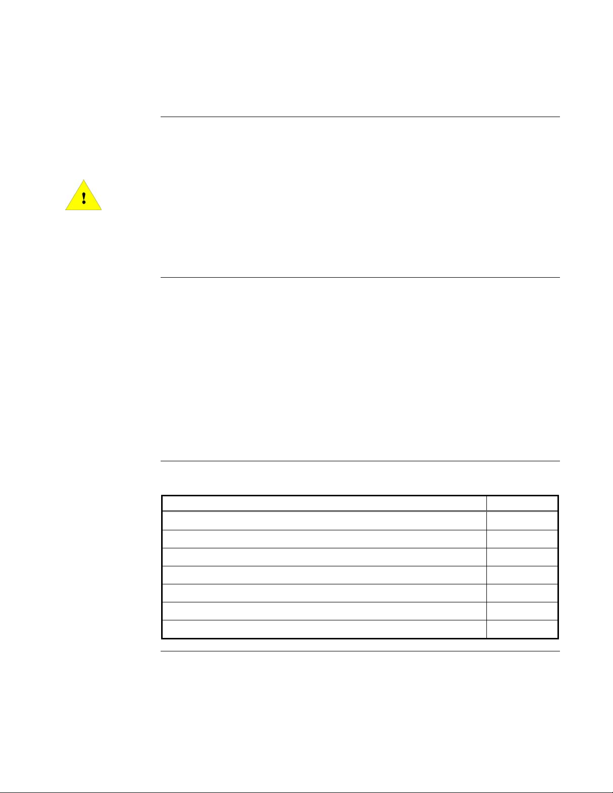
Regardless of the method, the basic concept behind controlling smoke is to use differences in air
pressure to minimize the spread of smoke and, if possible, vent it from the building.
You cannot confine smoke by simply closing all access ways (such as doors and vents) to the
room that has the fire in it. Even with these passages closed off, smoke can disperse throughout a
building via cracks, holes made for pipes and electrical wires, and spaces around doors and
windows. Smoke is driven through these small openings by the expanding gases from the fire.
Smoke can also be driven onto other floors by the “stack effect,” which causes air to rise in
buildings. The stack effect is caused by the difference in the interior and exterior temperature of
the building. The figure below shows how smoke can disperse throughout a building:
Adjacent Room
Adjacent Room
Adjacent Room
SMOKE
First Floor
Adjacent Room
Area On Fire
Adjacent Room
Figure 1-1. Smoke Infiltrating Rooms Adjacent to the Fire
Continued on next page
1-3
Controlling Smoke Movement, Continued
Basic Concept
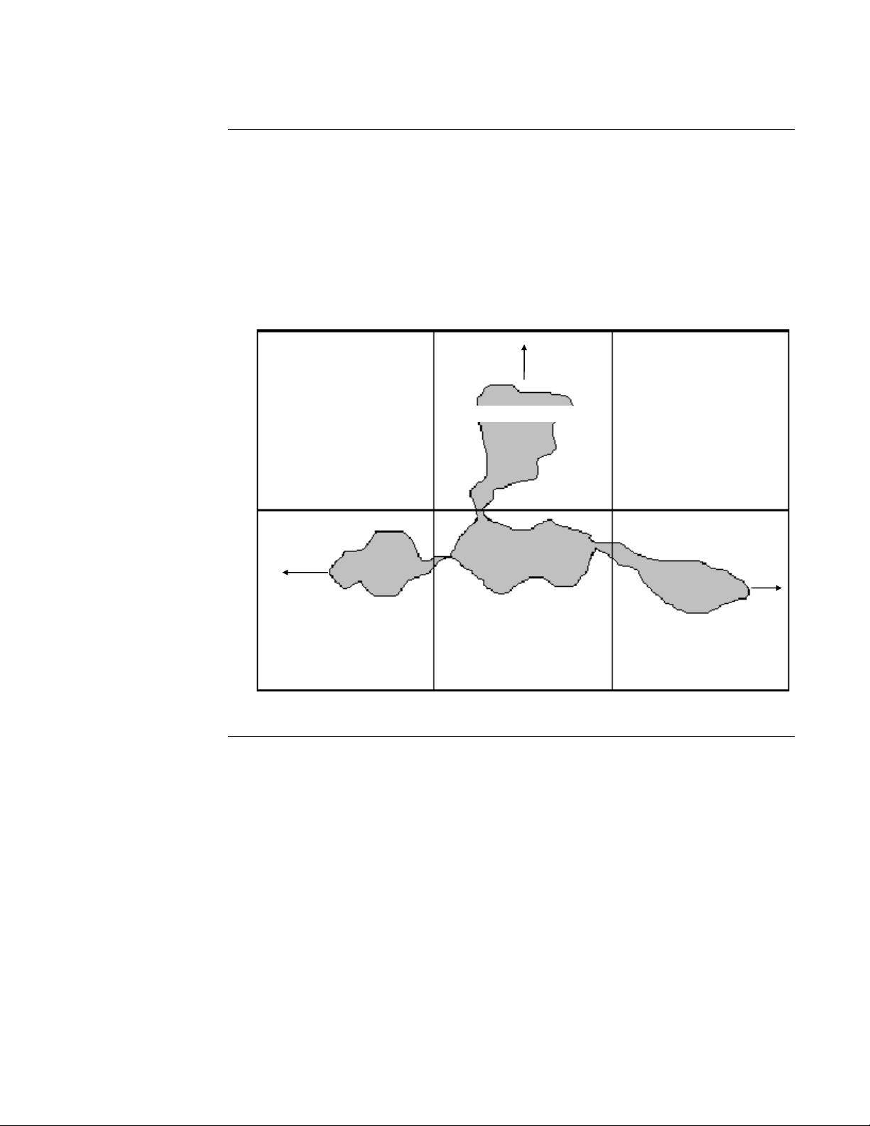
Since smoke is carried by the movement of air, you can stop the spread of smoke throughout the
building by lowering the air pressure in the area containing the fire and by raising the air pressure
in the surrounding areas and floors. The difference in air pressure (also called the “Air Pressure
Differential”) between the smoke-filled area and the surrounding areas acts as a barrier to the
smoke, pushing it back into the smoke-filled area. The figure below shows how this works.
FigureTag FD4-465-01
POSITIVE
AIR PRESSURE
POSITIVE
AIR
PRESSURE
POSITIVE
AIR PRESSURE
NEGATIVE
PRESSURE
POSITIVE
AIR PRESSURE
POSITIVE
AIR
PRESSURE
POSITIVE
AIR PRESSURE
Figure 1-2. Applying Positive Air Pressure to Control Smoke
1. Lower the air pressure in a smoke-filled area by controlling the air flow into it and turning
ON the exhaust fans from the area to full capacity. This “Negative Air Pressure” technique
pulls the smoke out of the area and vents it outside of the building.
2. Pressurize the areas and floors surrounding the fire by turning OFF all exhaust systems
(including closing any exhaust dampers) and forcing supply air to those areas at full capacity,
creating zones of “Positive Air Pressure.” The air in the pressurized areas tends to leak into
the smoke zone, using the same cracks and holes that the smoke would use to get out. This
positive pressure airflow into the burning room keeps the smoke from spreading.
POSITIVE
AIR PRESSURE
POSITIVE
AIR PRESSURE
Continued on next page
1-4
A
Controlling Smoke Movement, Continued
Basic Concept
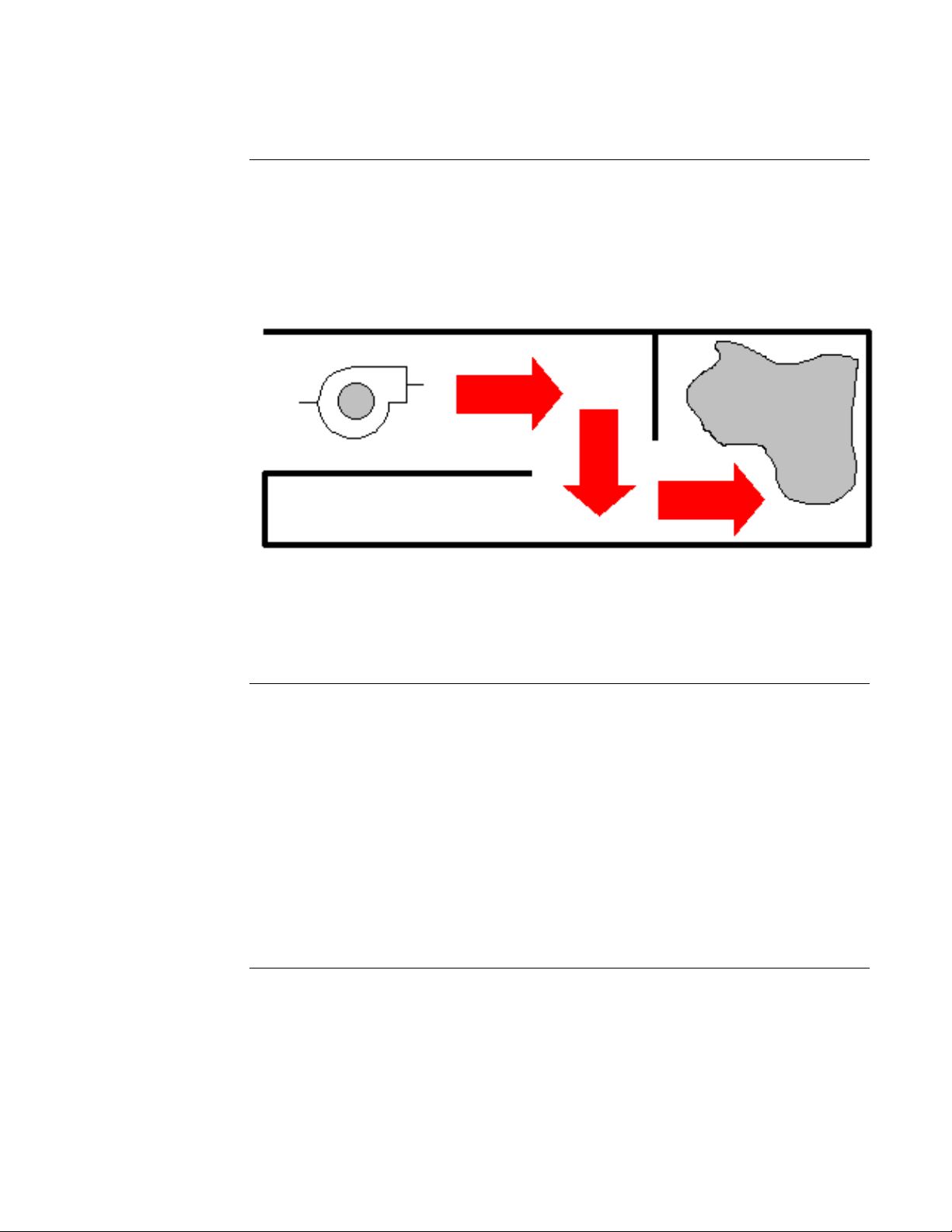
3. Turn OFF the air inlets and air returns of the areas that are neither being pressurized nor
depressurized (i.e., areas far away from the fire). Turning OFF the air return prevents the
smoke that is being vented into the return air system from coming into the smoke-free area.
In cases where there are large openings (such as an open doorway) between the area on fire
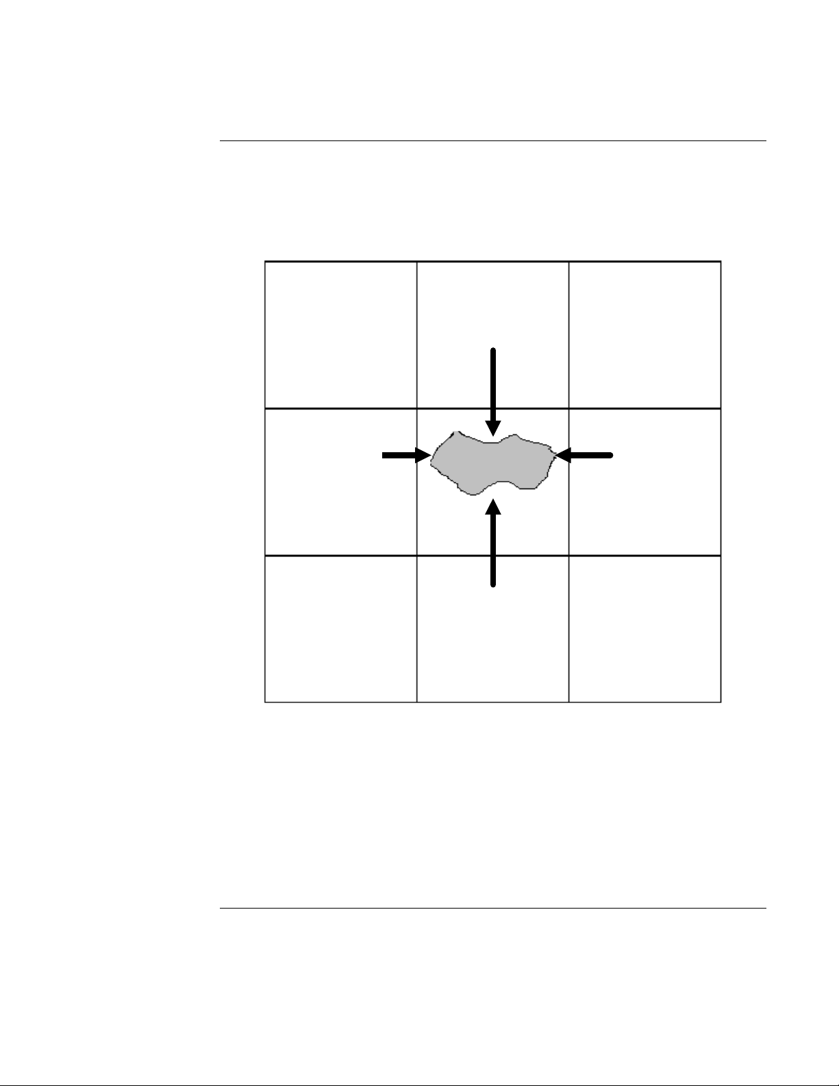
and an adjacent area, smoke can be confined by a large volume of air. Pumping large
amounts of air through the adjacent space creates a constant draft through the opening into the
smoke zone (as shown below).
IR
A
CENTRIFUGAL FAN
Figure 1-3. Confining Smoke with a Large Volume of Air
The draft through the open space keeps back the smoke, confining it to the smoke zone. The
amount of air required to keep the smoke from penetrating the open space is quite large. Avoid
this type of situation when possible.
I
R
AIR
SMOKE
Creating
Smoke Zones
To contain smoke by using pressure, you must divide the building into “Smoke Control Zones.” A
floor or several floors of the building can be considered a single zone or a single floor can be
broken into a number of zones. A zone must be separated from other zones by smoke dampers,
airtight doors, and smoke-proof barriers.
When a fire occurs, the smoke control system can then pressurize all of the zones around the zone
where the fire initiated (called the “Fire Zone”), isolating the smoke to that single zone.
If the smoke control system is non-dedicated, the layout of the smoke control zones should take
into consideration the layout of the HVAC system. You should place multiple areas served by the
same HVAC controls in the same smoke control zone. Also, the smoke control zones must
conform to any fire control zones that have been established, because the smoke detectors are tied
into the fire detection system. Also, keeping the smoke control zones and the fire control zones the
same makes it easier to coordinate the two systems.
1-5

Controlling Smoke Movement, Continued
Causes of
Smoke Movement
The following forces affect smoke movement:
Stack Effect:
When the outside air temperature is colder than the temperature inside a building, there is often an
upward movement of air within the building. This air move ment is most noticeable in stairwells,
elevator shafts, electrical risers, or mail chutes, and is referred to as “Normal Stack Effect.” This
phenomenon is most noticeable in tall buildings during winter, but can occur in a single story
building as well.
When the outside air temperature is warmer than the temp erature inside a building, there is often a
downward movement of air within the building. This air movement is referred to as “Reverse
Stack Effect.”
In a building with normal stack effect, the existing air currents can move smoke a considerable
distance from the fire origin. If the fire is below the neutral plane of the shaft (i.e., an elevation
where the hydrostatic pressure inside the shaft equals the hydrostatic pressure outside the shaft),
smoke moves with the building air in to and up the shaft. Once above the neutral plane, smoke
flows out of the shaft into the upper floors of the building.
Buoyancy:
Smoke from a high temperature fire has buoyancy due to its reduced density. In a building with
leakage in the ceiling of the fire room, this buoyancy-induced pressure can produce smoke
movement. In a fire room with only one opening to the building, air flows into the room while hot
smoke flows out of the room. If the fire room has open doors or windows, the pressure difference
across these openings is negligible because of the large flow areas involved. However, for a
tightly-sealed room, the pressure differences due to expansion may be important.
Wind:
Wind can also have a pronounced influence on smoke movement within a building. The effect of
wind velocity on the air movement within a well-constructed building is minimal. However, the
effects of wind can become important for loosely-constructed buildings or buildings with open
doors or windows.
Frequently in fires, a window breaks. If the window breaks on the side of the building away from
the wind (the leeward side), the negative pressure caused by the wind vents the smoke from the
fire room. This can greatly reduce smoke movement within the building. However, if the broken
window is on the windward side of the building, the positive pressure of the wind can force the
smoke throughout the fire floor, and possibly to other floors as well. This event can endanger lives
and hamper firefighters as well. Wind induced pressures can be quite large and can easily
dominate building air movement.
Continued on next page
1-6

Controlling Smoke Movement, Continued
Causes of
Smoke Movement
Managing
Smoke Movement
HVAC System:
Before the development of smoke control systems, HVAC systems were shut down when a fire
occurred. This is because an HVAC system frequently transported smoke during building fires.
In the early stages of a fire, HVAC smoke transport can be a good thing. When a fire starts, the
HVAC system can transport the smoke to a location where people can smell it and be alerted to
the fire (although they may not know where the smoke is coming from). However, as the fir e
progresses, the HVAC system transports the smoke to every area that it serves, endangering life in
all those places. To make matters worse, the HVAC system also supplies air to the fire, which aids
combustion.
Although shutting down the HVAC system prevents it from supplying air to the fire, this action
does not prevent the movement of smoke through the supply and return air ducts, air shafts, and
other building openings due to stack effect, buoyancy, or wind effect.
“Smoke Movement Management” includes all of the methods that can be used to modify and
control smoke movement for the benefit of the building occupants, firefighters, and for the
reduction of property damage. The use of barriers, smoke vents, and smoke shafts are traditional
methods of smoke management.
Barriers:
The effectiveness of barriers in limiting smoke movement depends on the leakage paths in the
barrier and on the pressure differen tial across the barrier. Holes where pipes penetrate floors or
walls, cracks around doors, and cracks in walls or between walls and floors are a few of the places
where smoke can leak through a barrier. The pressure differential across these barriers depends on
wind, buoyancy, stack effect, and the HVAC system.
Smoke Vents and Smoke Shafts:
The effectiveness of smoke vents and smoke shafts depends on their distance from the fire, the
buoyancy of the smoke, and the presence of other driving forces. In addition, when smoke is
sprinkler-cooled the effectiveness of smoke vents and smoke shafts is greatly reduced.
Elevator shafts in buildings have often been use d as smoke shafts. The obvious problem with this
is that it prevents the elevator from being used for fire evacuation (because of the “piston effect”
of an elevator), and frequently allows the smoke to travel between floors. Specially designed
smoke shafts which have no leakage can be used to prevent the distribution of smoke to fire-free
floors.
In summary, the effectiveness of barriers in a traditional smoke management system is limited to
the extent that the barriers are free of leakage paths. Smoke vents and smoke shafts are limited by
the fact that the smoke must have sufficient buoyancy to overcome other forces that may be
present.
In the last few years, motorized fans have been used to overcome the limitations of the traditional
systems. The systems that employ these motorized fans are called “Smoke Control Systems.”
These Smoke Control Systems rely on creating air pressure differences and positive or negative
airflows to limit and control the movement of smoke and other noxious gases.
1-7

Principles of Smoke Control Systems
System Types
Maintaining
System Integrity
Two types of smoke-control systems exist – Dedicated and Non-dedicated.
• Dedicated Smoke Control System: Is installed in a building for the sole purpose of
controlling smoke.
• Non-dedicated Smoke Control System: Uses parts of the building HVAC system to control
smoke.
In some cases, a building has both non-dedicated and dedicated systems. Non-dedicated systems
are used throughout the building for normal areas such as offices and manufacturing facilities.
Dedicated systems are used for special areas, such as elevator shafts, stairwells, stairtowers, and
other areas that need special smoke-handling techniques.
Smoke Control System products connect to HVAC equipment to form a system for controlling the
flow of smoke during a fire condition. Smoke-control systems are designed, installed, and
maintained so that a system remains effective and provides a “Tenable Environment” during
evacuation of the protected areas. A “Tenable Envir onment” as defined in NFPA 92A, is an
environment in which the quantity and location of smoke is limited or otherwise restricted to allow
for ready evacuation through the space.
A major concern with any emergency signaling system, whether burglary, fire, or smoke control,
is maintaining system integrity. This task is traditionally accomplished by electrical supervision of
wiring. However because the proper operation of the fans and dampers connected to the output
circuits may involve mechanical controls and pneumatic controls, as well as electrically-actuated
parts, end-process verification is provided. The end-process verification is provided to alert the
firefighter/operator that the fan or damper has operated in response to an automatic or manual
command issued during an emergency condition. While end-process verification confirms
operation during an emergency condition, system integrity during a non-emergency
(normal supervision) conditions is checked differently depending on whether the equipment is
non-dedicated or dedicated.
The operability of the non-dedicated smoke-control equipment is verified by the "comfort level" in
the areas that are served by the equipment. In other words, if the H VAC equipment is not
functioning properly, the building occupants are soon made aware of this and the problem can be
solved.
The operability of the dedicated smoke control equipment is verified by an automatic self-test that
is performed on a weekly basis.
1-8

Smoke Control and Fire Control System Differences
Separate System
for Separate Goals
The smoke control system is usually separate from the fire control system, since they have
different goals. The goal of the fire control system is to contain and extinguish the fire as fast as
possible. These systems, which halt the fire but not the smoke, are often triggered automatically,
relying on the heat of the fire to activate the system. Although smoke control systems are also
automatic, you must have manual overrides for the automatic controls.
A smoke control system may also be required to work with gas-based fire extinguishers, such as
gaseous agent systems installed in many computer rooms. If the smoke control system tries to vent
a room with such a system, it may vent the fire suppressing gas as well. Removing the gas lets the
fire continue burning. Also, pressurizing the areas surrounding an extinguisher equipped room
reduces the effectiveness of the system. Air forced into the room from the outside by pressure can
provide the fire with the oxygen it needs to continue burning. Therefore, gas-based fire
extinguishers and smoke control systems should not be active at the same time in the same
area.
The smoke control system receives the location of the fire from the fire panel. The fire panel uses
a combination of smoke and heat sensors to determine where the fire is located. As defined in
NFPA 92A: In the event that signals are received from more than one smoke zone, the smoke
control system will operate in the mode determined by the first signal received.
Specific, zoned smoke control strategies should never be triggered by manual pull boxes. The
risk of someone pulling a box someplace other than the fire zone is too high for you to trust your
smoke control system to this form of activation.
All smoke control systems installed in buildings must be in accordance with the standards
adopted by local codes. You can find additional information regarding fire alarm control units in
Underwriters Laboratories Standard UL 864 and the National Fire Protection Association (NFPA
®
).
1-9

Designing a Smoke Control System
Basic Goal
How to Begin
Engineering
Responsibility
The basic goal of the smoke control system is to maintain a tenable environment. A tenable
environment allows:
• The building occupants to evacuate safely from the building.
• The firefighters to get quickly to the fire zone.
The first step to take in designing a smoke control system is to lay out the smoke control zones,
as previously explained. After the smoke zones are established, address the following design
factors:
• The zone-by-zone smoke control plan.
• The amount of pressure needed to contain smoke.
• Proper separation between zones.
• The fans and duct work used in the smoke control syste m.
• Dampers required for smoke control.
• The air inlets and outlets used in the smoke control system.
Smoke control systems must be engineered by qualified personnel. Complete calculations of
system designs are the responsibilities of the Engineer of Record and go beyond the scope of this
publication. A high level of coordination is required between the engineers, Authority Having
Jurisdiction (AHJ), and system designers who are involved in the process.
Creating the
Zone-By-Zone
Smoke Control Plan
You must create a smoke control plan for each zone in your building. Each smoke control zone
plan consists of the number of steps the smoke control system must take to contain the smoke in
the building zone. For each zone, you must decide:
• Whether you should depressurize the zone if a fire occurs.
• If the zone is to be depressurized, by how much you should depressurize it.
• Which adjacent zones should be pressurized and how much pressure is required.
Some zones in a building may need special consideration. As mentioned earlier, zones that have
gas fire extinguisher systems should not be vented (depressurized) and the zones surrounding the
fire zone with such a system should not be pressurized. You may not be able to pressurize other
areas, such as hospital labs or biological research labs, due to the risk of contaminating
surrounding areas with germs or toxins from these facilities.
Consider the number of zones surrounding the fire zone that should be pressurized. While, in
theory, all you need to do is to pressurize all of the zones immediately surrounding the fire zone, it
is possible that smoke can find a way around the pressurized areas and infiltrate distant zones.
Thus, depending on the size of the building and the capacity of the smoke control system, you may
decide to pressurize more zones.
Note: An increase in the number of zones to be pressurized means a corresponding increase in
the size of the air supply system.
Make certain to write down the state that all fans, dampers, and other smoke control equipment
should be in to control smoke in each zone. Then program this information into the smoke control
system.
1-10

Designing a Smoke Control System, Continued
Determining the
Smoke Containment
Pressure
Since air pressure is what keeps smoke from spreading, the primary design factors are the amount
of pressure needed to confine the smoke, and the size of the system used to create this pressure.
For the smoke control system to create a barrier of air pressure betw een the smoke zone and
surrounding zones, the amount of pressure required varies with the height of the ceiling and
whether or not the building has a sp rinkler system. The table below gives examples of the
minimum pressure differential needed to keep smoke out of rooms surrounding the fire site as
defined in NFPA 92A.
Table 1-1. Examples of Fire Zone Minimum Pressure Differential
Sprinkler System Ceiling Height
Minimum Pressure
Differential (in.)*
Yes Any 0.05 in.
No 9 ft. 0.10 in.
No 15 ft. 0.14 in.
No 21 ft. 0.18 in.
* in. = Inches, Water Gauge
Pressure buildup in an area depends on the amount of leakage. Leakage occurs through joints,
cracks, openings for pipes and wires, gaps between doors and their door jams, and so forth.
The better the zone is sealed off from neighboring zones, the easier it is to maintain the required
pressure. Since larger openings, like normally-open doorways, require large amounts of air to
maintain pressurization, you should avoid this type of situation.
Separating Smoke
Zones Properly
Selecting the Proper
Fans and Duct Work
You must separate smoke zones from one another by “smoke barriers,” which prevent smoke from
passing through them. Smoke barriers can be a wall, a floor, or a ceiling. Any openings in the
smoke barrier must be closed with a smoke-proof fitting. For example, any duct work going
through a smoke barrier must have “smoke dampers” installed. A smoke damper is a damper that
prevents smoke from passing through it when fully closed. During a smoke emergency all of the
fittings should seal themselves, so that smoke cannot penetrate the barrier.
Since the smoke control zones should be the same as the fire control zones, you usually separate
your zones with a “fire-rated partition.” A fire-rated partition is a wall that is built of fire resistant
materials and that reaches from floor to ceiling. Different floors should be separated by a “firerated ceiling,” a ceiling made of fire-resistant materials. Both fire-rated partitions and fire-rated
ceilings are rated for the amount of time they can withstand a fire. Any openings in a fire-rated
partition or ceiling must be capable of being sealed with a fire-rated closure, such as a fire-rated
door or fire damper.
The fans and duct work used in the smoke control system must be capable of providing the
amount of pressure you calculated earlier. In a non-dedicated system, this may mean that you
need to install fans that have a higher capacity than the HVAC system normally requires. The
ducts must be capable of taking the pressurization (or the depressurization, for the fire zone's
return duct) that the smoke control system demands. Both the fans and the ducts should meet local
requirements such as those stated in NFPA 90A, Standard for the Installation of Air Conditioning
and Ventilating Systems.
Continued on next page
1-11

Designing a Smoke Control System, Continued
Selecting the Proper
Fans and Duct Work
Choosing the
Proper Dampers
Fans must be capable of reaching the required pressure setting within 60 seconds. Each fan must
also have a pressure monitor so that the smoke control system can receive feedback on the status
of the fan to determine whether it is actually working. It is the responsibility of the system
designer to select duct work that meets the temperature and fire ratings for the specific application.
In some climates, the outside air can be so cold that drawing it directly inside the building for
pressurization can damage the building's interior fixtures or equipment (e.g., freeze pipes or
damage temperature-sensitive equipment). In these cases, some sort of pre-heater needs to be
installed on the air inlet. The smoke control system does not need to control this air intake heater
as closely as one on an HVAC system, since maintaining comfort levels is not an issue. It simply
has to make sure the air sent into an area is warm enough to not damage the building's equipment.
The dampers used to isolate the smoke zone must be smoke dampers. Smoke dampers are dampers
that meet the requirements given in UL 555S, Standard for Leakage Rated Dampers for Use in
Smoke Control Systems. Following this standard ensures that the dampers are able to block the
smoke when they are fully closed. These dampers may be different from those you might use in an
HVAC system that does not perform smoke control.
In a smoke control system, the dampers must be able to travel to their desired setting in a maximum
time of 75 seconds (see note below). All dampers must be fitted with end-position switches to
provide feedback to the smoke control system. These switches let the control system know the
position of the dampers, since smoke dampers are usually either fully-closed or fully-open.
Note: Local codes may specify a shorter maximum time.
Dampers sometimes function as both smoke dampers and fire dampers. Fire dampers are dampers
that block a fire from penetrating a fire-rated partition via a duct. These dampers are normally
open, held in place by a fusible link. The fusible link is a heat-sensitive device that releases the
dampers when it is heated to a certain temperature. Once the fusible link releases, the dampers
close by the force of gravity. This is required so that fire dampers operate even if the local electric
service has failed. The specifications for fire dampers appear in UL 555, Standard for Fire
Dampers.
Placing Air Inlets
and Outlets
If you want a damper to function as both a smoke damper and a fire damper, it must meet the
requirements for both devices. A damper can be operated by an electric motor or pneumatics.
However, it must have a fusible link or some other means of auto matic closure (like a regular fire
damper). Since the control system can override the damper closure if the temperature warrants, the
damper needs the fusible link in case the damper’s automatic control is interrupted.
You need to carefully consider the placement of the air inlets and outlets on your building. If you
place an outlet that vents smoke too close to an air inlet, the air intake can draw the smoke back
into the building. Since smoke rises, the exhausts that vent smoke should be placed well above air
inlets. The exhausts should be placed several feet above the roof level to allow space for the
smoke to rise and disperse.
Keeping smoke outlets far away from air inlets does not guarantee that the air brought into the
building is always smoke free. You may want to place smoke detectors in air inlets that operate
during a smoke emergency.
Note: In some cases, smoke detection in the air inlet is required to have the capability of being
overridden by the responding authori t y after t he situat i o n has been investigated.
If the detector finds smoke in the incoming air, it alerts the control system. The control system
must then decide whether or not to shut down the air inlet.
1-12
Designing a Dedicated Smoke Control System
Introduction
About Stairtowers
Most of the systems discussed so far have been non-dedicated systems. Even in a building where
the primary smoke control system is non-dedicated, special zones or functions may exist that
require a “dedicated” system. The most common example of a dedicated system is a dedicated
smoke control system for a stairtower.
A “stairtower” is a stairwell with a ventilation system that is isolated from the main building.
The only connection between the building and the stairtower are fire-rated doors on each floor.
Since the building occupants should use the stairtower to leave during an evacuation, keeping the
stairtower smoke-free is vital.
A stairtower has its own dedicated system that pressurizes the stairtower to keep smoke out.
This dedicated system can take several forms, from a fan mounted in the roof of the stairtower, to
a duct system that delivers air to each level.
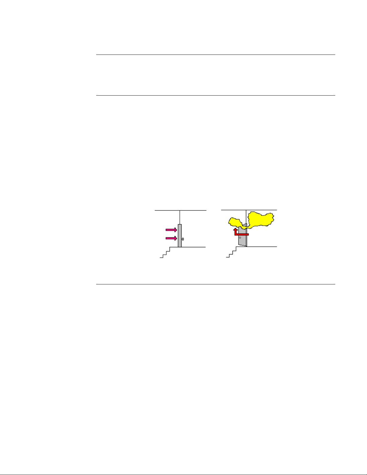
You must pressurize a stairtower enough to keep smoke out. However, if the pressure in the
stairtower is too great, then opening the doors leading into the stairtower can be difficult.
(See the figure below.)
Too Much Pressure
Building
Too Little Pressure
Building
Stairtower
Stairtower
Figure 1-4. The Effects of Too Much or Too Little Pressure
1-13
Designing a Dedicated Smoke Control System, Continued
Designing the Ideal
Stairtower System
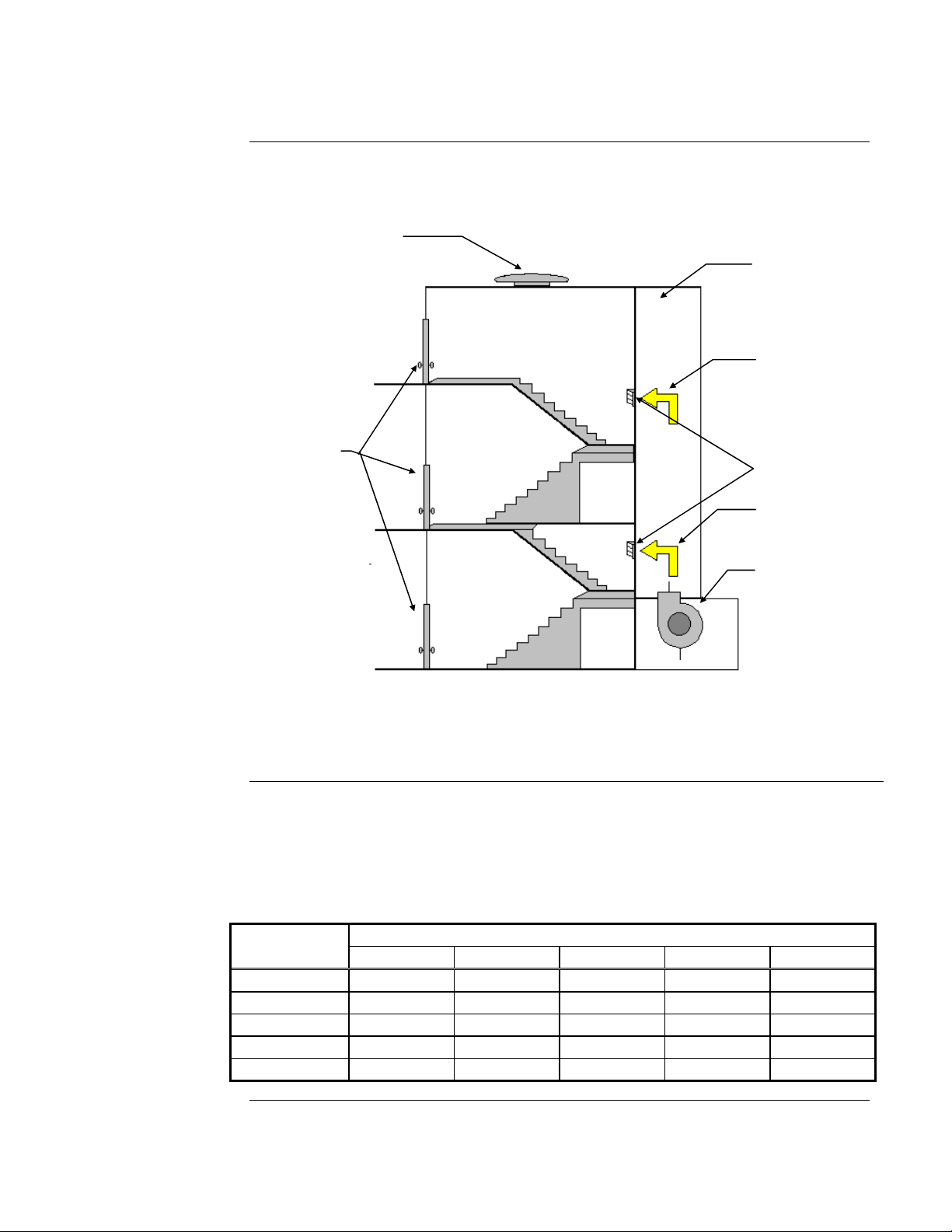
The ideal stairtower smoke control system must pressurize the stairway enough to keep the smoke
out, but it must not pressurize it so much that the doors cannot be opened. An example of a
dedicated smoke control system for a stairtower is shown in the figure below.
Exhaust Fan
Air Supply Duct
Air Flow
Fire Rated
Doors
Pressure Vents
Air Flow
Supply Fan
Ensuring Doors
Can Open
Figure 1-5. Stairtower Pressurization by Multiple Injections
The figure above shows stairtower pressurization by multiple injections with a supply fan located
at ground level and an exhaust fan located on th e building roof.
The table below shows the maximum allowable pressure differential across a door in inches water
gauge (in.) based on how wide the door is and how much force the automatic door closing
mechanism exerts as defined in NFPA 92A. At the pressures shown in the table, the door requires 30
lbf (pounds of force) to open, the maximum limit suggested by the NFPA Life Safety Code (NFPA
101).
Table 1-2. Pressure Differential For Various Door Widths
.
Door Closer
Force (lbf)
6
8
10
12
14
32 in. 36 in. 40 in. 44 in. 48 in.
0.45 0.40 0.37 0.34 0.31
0.41 0.37 0.34 0.31 0.28
0.37 0.34 0.30 0.28 0.26
0.34 0.30 0.27 0.25 0.23
0.30 0.27 0.24 0.22 0.21
Pressure Differential
Continued on next page
1-14
Designing a Dedicated Smoke Control System, Continued
Ensuring Doors
Can Open
Controlling Pressure
in a Stairtower
Table 1-2 assumes a door height of seven feet and a distance from the doorknob to the knob side
of the door of three inches. If your door does not meet these requirements, or has opening
hardware other than a doorknob, such as panic hardware, then refer to the ASHRAE publication
Design of Smoke Control Systems for Buildings for a formula to calculate the proper opening
force. The door widths in Table 1-2 are only valid for doors that are hinged at one end. For other
types of doors, see the ASHRAE document.
Many door closers vary the amount of force as the door opens. They provide less resistance in the
early stages of opening the door than they do later, when the door is almost fully open. The force
to open the door shown in Table 1-2 represents the force needed to open the door only enough to
let air flow through the opening. Once air is able to flow, the force exerted by the difference in air
pressure on the door lessens. Therefore, when calculating the force required to open the door, you
may need to lower the door closer force.
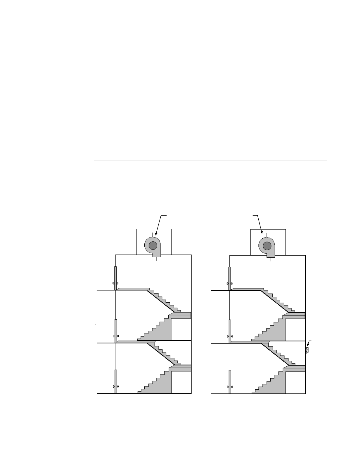
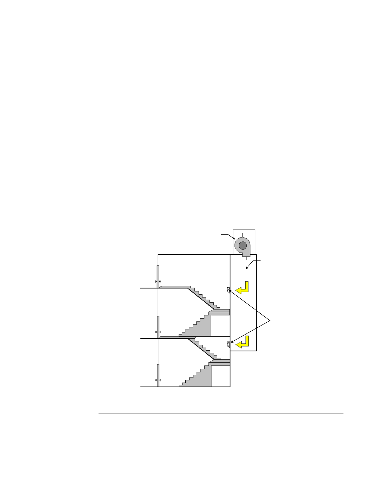
Stairtower smoke control systems are divided into two categories: “non-compensated” and
“compensated.” These categories are illustrated in the figure below, which shows stairtower
pressurization by top injection. Non-compensated systems simply turn on a fan to pressurize the
stairtower, as shown below in Stairtower A. The fan speed doe s not cha nge to compensate for
doors opening and closing. The more doors that are open, the more the pressure differential
between the stairtower and the building drops.
Constant
Fan Speed
Variable
Fan Speed
Stairtower A
Stairtower B
Figure 1-6. Non-Compensated and Compensated Stairtower Systems
Continued on next page
1-15
Vent
Designing a Dedicated Smoke Control System, Continued
Controlling Pressure
in a Stairtower
The building shown in Figure 1-6, Stairtower A has no vent to the outside. Compen sated systems
adjust the airflow to make up for pressure lost through open doors. A compensated system
(Figure 1-6, Stairtower B) can use dampers (or vents) to relieve excess pressure in the stairtower
to ensure that the pressure does not go over the maximum limit.
There are a number of ways compensated stairtower smoke control systems can control
pressurization. In a basic system with a roof-mounted fan blowing air into the stairtower, pressure
can be regulated by varying the speed of the fan, the pitch of the fan bla de, t he inlet vanes , or the
number of fans operating (assuming there is more than one).
More sophisticated systems use ducts to deliver air to several points in the stairtower. The
dampers can be controlled to maintain the appropriate pressure in their zone. Duct systems can
also use bypass dampers and ducts to control the amount of air flowing from the fan to the outlets.
The bypass dampers are opened when the stairtowe r is at the proper pressure, so that excess air
flows into the bypass duct, then back to the air inlet not into the duct system.
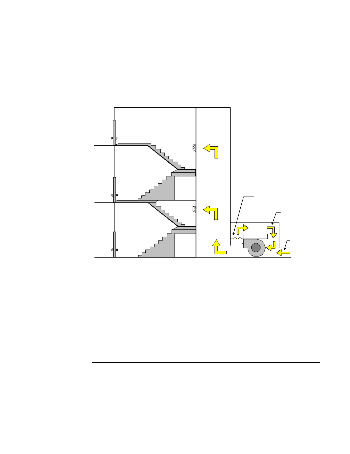
The figure below shows a stairtower pressurization system that uses multiple pressure injection
dampers mounted in an air pressure duct. In this example, the vents to the building have
barometric dampers. While a roof-mounted fan is shown in the figure, the fan can be located at
any level. A manually-operated damper may be located at the top of the stairtower to aid the fire
department in purging smoke from the building during a fire.
Pressurization Fan
Air Pressure Duct
Dampers
Figure 1-7. Stairtower Pressurization by Multiple Injections (Roof-Mounted Fan)
Continued on next page
1-16
Designing a Dedicated Smoke Control System, Continued
Controlling Pressure
in a Stairtower
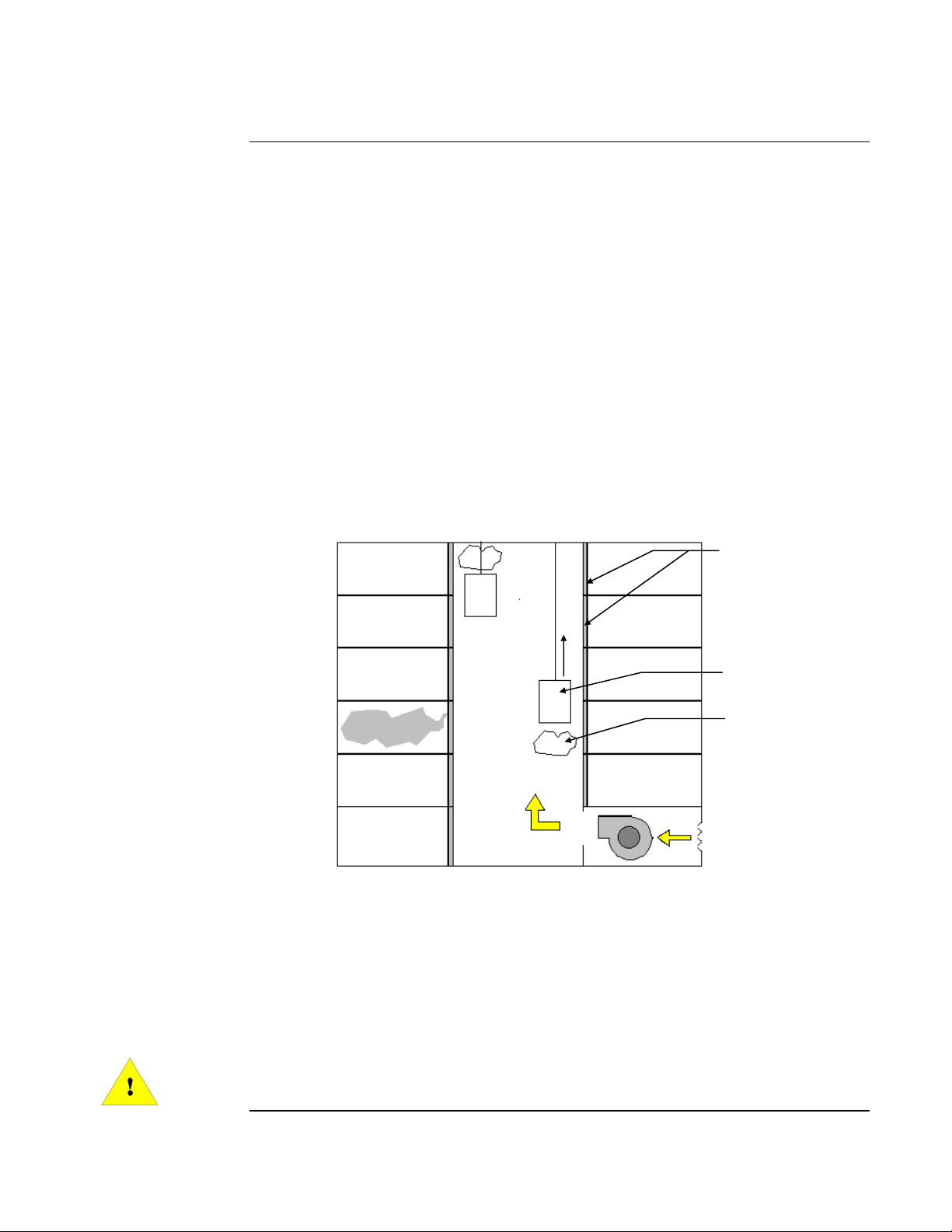
The figure below shows a bypass pressure control system for stairtower pressurization with the
bypass-around supply fan located at ground level. Although a ground-level fan is shown, the fan
can actually be placed at any level. The bypass duct dampers are controlled by one or more static
pressure sensors located between the stairtower and the building. In addition, a manually-operated
damper may be located at the top of the stairtower for smoke purging by the fire department.
Bypass Duct Dampers
Bypass Duct
Air Intake
Figure 1-8. A Bypass Pressure Control System
There are several ways for a compensated stairtower smoke control system to get rid of excess air
pressure to ensure that the stairtower doors can open properly. One or more vents to the building
exterior (with dampers) can be used in the stairtower to release excess pressure. These dampers
can be barometrically controlled (being force d open by the excess air pressure) or controlled by
electric motors or pneumatics as in conventional HVAC systems. In both cases, the dampers must
be placed far enough away from the air supply to prevent venting of air that has not yet been able
to disperse through the stairtower. Vents can also lead into the building, but you should consider
carefully the impact of venting extra pressure into the building before using this type of vent.
You can also use an exhaust fan to vent the excess pressure from the stairtower. Such a fan should
be designed to operate only when the stairtower is over-pressurized. It should never be on when
the pressure differential between the building and the stairtower is below the lowest limit.
1-17
Designing a Dedicated Smoke Control System, Continued
Elevator Smoke
Control
Most elevators do not have smoke protection, fire prot ect ion , or ot her features necessary for them
to be considered as a means for fire evacuation. Elevator systems not specifically designed and
built for fire evacuation should not be used in fire situations.
The elevator smoke control system is intended to prevent smoke flow to other floors by way of the
elevator shaft. Elevator shafts present a special menace with regards to smoke control. An elevator
shaft makes a perfect chimney to draw smoke into the upper levels of a building. Since elevators
usually have openings on each floor, and the seals on the elevator doors are often poor, the
elevator shaft can become a mechanism to spread smoke throughout a building. Smoke control in
an elevator shaft is an important consideration in the overall smoke control plan.
The problems resulting from smoke migration through elevator shafts are illustrated by the
MGM Grand Hotel fire. Although the fire occurred on the ground floor, the smoke from that fire
migrated through the elevator shafts to the upper floors resulting in a number of fatalities.
An obvious solution to this problem is to pressurize the elevator shafts, as shown in the figure
below. However, pressurizing an elevator shaft presents a number of problems. While the elevator
doors can be fitted with improved seals and rubber sweeps, these systems will not totally eliminate
air leakage. Also, most elevator shafts are not designed to be pressurized. They often have large
openings at the top where the cables feed into the winding room. Shafts are often constructed of
porous material that cannot contain the air pressure. And since most shafts are not desig ned to be
inspected after the elevators are installed, finding and repairing cracks that would let smoke
infiltrate or pressure escape is difficult.
Special Smoke-Proof
Elevator Doors
Elevator
Smoke
Low Pressure
Area Created by
Elevator Door
Figure 1-9. Pressurizing an Elevator Shaft to Prevent Smoke Migration
Even if the shaft is pressurized, another primary problem is caused by the transient pressures
produced when an elevator car moves inside the shaft during a smoke emergency. This “piston
effect” can pull smoke into a normally pressurized elevator lobby or elevator shaft. For example,
an elevator car moving down from the top of the shaft may create a small low air pressure zone
near the top of the shaft, which can pull smoke from the fire zone into the shaft.
At the present time, these issues have not been resolved. Pressurizing the elevator shafts so that
the elevators can operate during a smoke emergency is still being studied.
IMPORTANT: In general, elevators should not be used as an escape route during
an evacuation.
1-18
 Loading...