

Page 1
574-xxx
Rev. 4
Fire
Australian
Installation
Manual
4100ES-S1 Fire Indicator Panel
Installation & Maintenance
Australian
Installation &
Maintenance
Manual
LT0394
Issue 1.5
Page 2

Page 3

iii
Copyrights and Trademarks
2006, 2012 Tyco Australia Pty Limited. All Rights Reserved.
All specifications and other information shown were current as of document revision date,
and are subject to change without notice.
Tyco, Simplex, the Simplex logo, MAPNET II, IDNet, TrueAlarm, SmartSync,
WALKTEST, MINIPLEX, and TrueAlert are trademarks of Tyco International Services
AG or its affiliates in the U.S. and/or other countries. VESDA is a trademark of Xtralis.
Simplex fire alarm technology is protected by the following U.S. Patent Numbers:
TrueAlarm analog smoke detection: 5,155,468; 5,173,683 and 5,543,777. IDNet and
MAPNET II addressable communications; 4,796,025. TrueAlert addressable notification;
6,313,744 and 6,426,697. SmartSync horn/strobe control; 6,281,789.
Australian Standard AS 4428.1
ActivFire Listing Number afp1682
The 4100ES-S1 is a Fire Indicator Panel manufactured by Tyco Fire Protection Products
for:
Tyco Services Fire & Safety
47 Gilby Road
Notting Hill
VIC 3168
AUSTRALIA
Phone : (03) 9538-7220
Fax : (03) 9538-7255
Name
Serial #
Manufacture Date
Approvals
Manufacture
Product / Site
Page 4

iv
Non-Disclosure Agreement
Tyco (THE COMPANY) and the User of this/these document(s) desire to share
proprietary technical information concerning electronic systems.
For this reason the company is disclosing to the User information in the form of this/these
document(s). In as much as the company considers this information to be proprietary and
desires that it be maintained in confidence, it is hereby agreed by the User that such
information shall be maintained in confidence by the User for a period of TEN YEARS
after the issue date and only be used for the purpose for which it was supplied.
During this period, the User shall not divulge such information to any third party without
the prior written consent of the company and shall take reasonable efforts to prevent any
unauthorised disclosure by its employees. However, the User shall not be required to
keep such information in confidence if it was in their possession prior to its receipt from
the company; if it is or becomes public knowledge without the fault of the User; or the
information becomes available on an unrestricted basis from a third party having a legal
right to disclose such information.
The User's receipt and retention of this information constitutes acceptance of these terms.
This information is copyright and shall not be reproduced in any form whatsoever.
The 4100ES-S1 Fire Indicator Panel provides a configuration programming facility,
which may be accessed via a programming computer using a “dongle”. Because this
programming facility allows the user to define in detail the operation of the 4100ES-S1
System being customised, changes may be made by the user that prevent this installation
from meeting statutory requirements.
The Company, therefore cannot accept any responsibility as to the suitability of the
functions generated by the user using this programming facility.
End User Liability Disclaimer
Page 5

v
Model Number & Firmware Revision
This manual applies to product with the following:
Model number : 4100ES-S1
Firmware revision : 1.02.04 and on
Document Name : LT0394 4100ES-S1 Installation & Maintenance Manual
Issue : V1.5 14 June 2012
5 July 2006 Issue 1.0 Original based on LT0350 1.0.7
6 October 2006 Issue 1.1 References to LT0432 and 1976-181 Wiring Diagrams
added.
30 Nov. 2006 Issue 1.2 Updated drawings 1976-181 Sheets 102, 203, 500.
23 Jan. 2007 Issue 1.3 Changes to T-GEN connection, checking system wiring.
21 Feb. 2007 Issue 1.4 Changes to AIU/PPU Brigade Interface mounting
14 June 2012 Issue 1.5 Changes for 4100ES introduction
Document
Amendment Log
Page 6
vi
Cautions, Warnings, and Regulatory Information
READ AND SAVE THESE INSTRUCTIONS. Follow the instructions in this
installation manual. These instructions must be followed to avoid damage to this product
and associated equipment. Product operation and reliability depends upon proper
installation.
DO NOT INSTALL ANY SIMPLEX® PRODUCT THAT APPEARS DAMAGED.
Upon unpacking your Simplex product, inspect the contents of the carton for shipping
damage. If damage is apparent, immediately file a claim with the carrier and notify your
Simplex product supplier.
SAFETY HAZARD - The 4100ES-S1 CPU Card includes a lithium battery. There is
danger of explosion if the battery is incorrectly replaced. Replace only with the same
or equivalent type recommended by the manufacturer. Dispose of used batteries according
to the manufacturer‟s instructions.
ELECTRICAL HAZARD - Disconnect electrical field power when making any internal
adjustments or repairs. All repairs should be performed by a representative or authorized
agent of your local Simplex product supplier.
STATIC HAZARD - Static electricity can damage components. Therefore, handle as
follows:
Ground yourself before opening or installing components (use a suitable wrist-strap
and cable clipped to the frame or an earth connection of the 4100ES-S1).
Prior to installation, keep components wrapped in anti-static material at all times.
EYE SAFETY HAZARD - Under certain fibre optic application conditions, the optical
output of this device may exceed eye safety limits. Do not use magnification (such as a
microscope or other focusing equipment) when viewing the output of this device.
RADIO FREQUENCY ENERGY - This equipment generates, uses, and can radiate
radio frequency energy and if not installed and used in accordance with the instruction
manual, may cause interference to radio communications. It has been tested and found to
comply with the limits defined in AS 4428.0-1997 and Amendment 1:2002.
SYSTEM REACCEPTANCE TEST AFTER SOFTWARE CHANGES - To ensure
proper system operation, this product must be tested in accordance with AS 1670 after
any programming operation or change in site-specific software. Reacceptance testing is
required after any change, addition or deletion of system components, or after any
modification, repair or adjustment to system hardware or wiring.
IMPORTANT: Verify 4100ES Programmer, Executive, and Slave Software
compatibility when installing or replacing system components. Refer to the relevant
Product Bulletins from Simplex Fire Products Australia (www.simplexfire.com.au) for
compatibility information.
Page 7

vii
Table of Contents
Copyrights and Trademarks ........................................................................................... iii
Approvals ........................................................................................................................ iii
Manufacture .................................................................................................................... iii
Product / Site .................................................................................................................. iii
Non-Disclosure Agreement ............................................................................................ iv
End User Liability Disclaimer .......................................................................................... iv
Model Number & Firmware Revision ............................................................................... v
Document ........................................................................................................................ v
Amendment Log .............................................................................................................. v
Cautions, Warnings, and Regulatory Information ........................................................... vi
Table of Contents .......................................................................................................... vii
List of Figures ............................................................................................................... xiii
List of Tables ................................................................................................................ xiv
Chapter 1 Introduction to the 4100ES-S1 Fire Alarm System .........1
Introduction .................................................................................................................. 1
In this Chapter ............................................................................................................. 1
Basic Configuration.......................................................................................................... 2
Overview ...................................................................................................................... 2
System Design ............................................................................................................. 2
4100ES-S1 Part Codes ................................................................................................... 3
Overview ...................................................................................................................... 3
Assemblies, Cards & & Modules ................................................................................. 3
Kits ............................................................................................................................... 3
Labels (expansion/spares) ........................................................................................... 4
Looms (expansion/spares) .......................................................................................... 4
4100 Part Codes (Non-4100ES) ...................................................................................... 4
Glossary ........................................................................................................................... 5
Chapter 2 Installing 4100ES-S1 Components ..................................2-1
Introduction .............................................................................................................. 2-1
In this Chapter ......................................................................................................... 2-1
Introduction to 4100ES-S1 Cabinet ............................................................................. 2-2
Overview .................................................................................................................. 2-2
Bays ......................................................................................................................... 2-2
CPU Motherboard .................................................................................................... 2-3
CPU Card................................................................................................................. 2-4
CPU Card LEDs ....................................................................................................... 2-5
Operator Interface .................................................................................................... 2-6
Additional CPU Motherboard Modules ................................................................... 2-6
System Power Supply (SPS) ................................................................................... 2-6
The Power Distribution Interface (PDI) .................................................................... 2-8
Mains Outlet ............................................................................................................. 2-8
Page 8

viii
Step 1. Mounting Cabinets .......................................................................................... 2-9
Overview .................................................................................................................. 2-9
Step 2. Mounting Card Bays to Cabinets .................................................................... 2-9
Overview .................................................................................................................. 2-9
Step 3. Configuring Cards ........................................................................................... 2-9
Overview .................................................................................................................. 2-9
CPU Motherboard Configuration ............................................................................. 2-9
CPU Daughter Card Configuration ........................................................................ 2-10
SPS Configuration ................................................................................................. 2-10
PDI Configuration .................................................................................................. 2-10
Configuring Other Cards ........................................................................................ 2-10
Step 4. Interconnecting Modules and Bays ............................................................... 2-11
Overview ................................................................................................................ 2-11
Guidelines .............................................................................................................. 2-11
Card Interconnections in the CPU Bay .................................................................. 2-11
Card Interconnections Within Expansion Bay ....................................................... 2-11
Basic Bay-To-Bay Interconnections ...................................................................... 2-11
Connecting to Motherboards ................................................................................. 2-12
Step 5. Installing Modules into Expansion Bays ........................................................ 2-13
Overview ................................................................................................................ 2-13
Placement Guidelines ............................................................................................ 2-13
Installing 4” X 5” Cards .......................................................................................... 2-15
Installing Motherboards ......................................................................................... 2-16
Step 6. Installing LED/Switch Modules into Expansion Bays .................................... 2-17
Overview ................................................................................................................ 2-17
The LED/Switch User Interface ............................................................................. 2-18
LED/Switch Controller Card ................................................................................... 2-18
Configuring the LED/Switch Controller Card ......................................................... 2-19
Mounting LED/Switch Modules to the Expansion Bay .......................................... 2-19
Mounting the Additional LED/ Switch Controller Card ........................................... 2-20
LED/Switch Modules .............................................................................................. 2-21
Wiring Instructions ................................................................................................. 2-21
4100ES Fan Control Module ..................................................................................... 2-22
Overview ................................................................................................................ 2-22
Labelling................................................................................................................. 2-22
Mounting & Connection ......................................................................................... 2-22
Programming ......................................................................................................... 2-22
Installing Other Modules ............................................................................................ 2-24
Chapter 3 Networking ........................................................................3-1
Introduction .............................................................................................................. 3-1
In this Chapter ......................................................................................................... 3-1
Network Configuration ................................................................................................. 3-2
Overview .................................................................................................................. 3-2
Ring and Star Configurations................................................................................... 3-2
Connecting Loops .................................................................................................... 3-3
System Design ......................................................................................................... 3-3
Getting Started ............................................................................................................. 3-4
Overview .................................................................................................................. 3-4
Introduction to the 4100 Network Interface Card (NIC) ............................................... 3-4
Overview .................................................................................................................. 3-4
Network Module Illustrations.................................................................................... 3-5
NIC Card LED Indications ........................................................................................ 3-5
Page 9

ix
NIC Media Cards ..................................................................................................... 3-6
Requirements and Limitations ................................................................................. 3-7
Step 1. Configuring Network Cards ............................................................................. 3-7
Overview .................................................................................................................. 3-7
CPU Motherboard Jumper Settings ........................................................................ 3-7
NIC Card Address Setting ...................................................................................... 3-7
NIC Card Jumper Settings ...................................................................................... 3-8
Wired Media Card Jumper Settings ........................................................................ 3-8
Step 2. Mounting Media Cards to the NIC ................................................................... 3-9
Overview .................................................................................................................. 3-9
Media Card Mounting .............................................................................................. 3-9
Step 3. Mounting Network Cards in the 4100ES-S1 ................................................... 3-9
Step 4. Wiring Network Cards ................................................................................... 3-10
Overview ................................................................................................................ 3-10
Wiring Guidelines ................................................................................................... 3-10
Wiring Distances .................................................................................................... 3-11
Fibre-Optic Wiring .................................................................................................. 3-12
Fibre Optic Connection Types ............................................................................... 3-12
4190-9010 Coupler Requirements ........................................................................ 3-13
Wiring with the Wired Media Card ......................................................................... 3-14
Loop Wiring, mixed Fibre and Cable ..................................................................... 3-16
Chapter 4 The System Power Supply & Alarm Relay Card .............4-1
Introduction .............................................................................................................. 4-1
In this Chapter ......................................................................................................... 4-1
SPS Specifications ...................................................................................................... 4-2
Input/Output/BatterySpecifications .......................................................................... 4-2
SPS Current Consumption ...................................................................................... 4-3
SPS Adjustments ......................................................................................................... 4-4
Adjusting Voltages ................................................................................................... 4-4
Setting Jumpers and DIP Switches ......................................................................... 4-4
SPS LED Indications ................................................................................................... 4-5
Status LEDs ............................................................................................................. 4-5
Troubleshooting an SPS .............................................................................................. 4-6
Overview .................................................................................................................. 4-6
“IDNet Power Monitor Trouble” ............................................................................... 4-6
“Extra Device” .......................................................................................................... 4-6
“Class A Trouble” ..................................................................................................... 4-6
“Earth Fault Search” ................................................................................................ 4-6
“Short Circuit” ........................................................................................................... 4-6
“Channel Fail” .......................................................................................................... 4-6
“No Answer/ Bad Answer” ....................................................................................... 4-6
“Output Abnormal” ................................................................................................... 4-6
The Alarm Relay Card ................................................................................................. 4-7
Overview .................................................................................................................. 4-7
Mounting (factory installed)...................................................................................... 4-7
Configuration ........................................................................................................... 4-8
Notes ........................................................................................................................ 4-8
Warning .................................................................................................................... 4-8
Specification ............................................................................................................ 4-8
Brigade Interfaces ........................................................................................................ 4-9
Overview .................................................................................................................. 4-9
Format ...................................................................................................................... 4-9
Page 10

x
Applications.............................................................................................................. 4-9
Kit Contents ............................................................................................................. 4-9
Door Mounting ......................................................................................................... 4-9
General Wiring ....................................................................................................... 4-10
Brigade Interfaces, Continued ................................................................................... 4-10
AIU/PPU Mounting ................................................................................................. 4-10
AIU/PPU Wiring ..................................................................................................... 4-10
ASE Mounting ........................................................................................................ 4-10
ASE Wiring............................................................................................................. 4-10
Chapter 5 SPS Field Wiring (4100ES-S1) ..........................................5-1
Introduction .............................................................................................................. 5-1
In this Chapter ......................................................................................................... 5-1
General Field Wiring Guidelines .................................................................................. 5-2
General Guidelines .................................................................................................. 5-2
SPS NAC Field Wiring Guidelines ............................................................................... 5-3
Overview .................................................................................................................. 5-3
Guidelines ................................................................................................................ 5-3
Allocations................................................................................................................ 5-3
Class A (loop) NAC Wiring ...................................................................................... 5-4
Class B (string) NAC Wiring .................................................................................... 5-5
Power Supply Wiring Distances .................................................................................. 5-6
Overview .................................................................................................................. 5-6
Class A NAC Wiring Table ...................................................................................... 5-6
Class B NAC Wiring Table ...................................................................................... 5-7
Using T-GEN 50 with 4100ES-S1 ............................................................................... 5-8
Overview .................................................................................................................. 5-8
Powering the T-GEN 50 .......................................................................................... 5-8
Controlling a T-GEN 50 with a Relay Module ....................................................... 5-10
T-GEN 50 Setting for Relay Operation .................................................................. 5-11
Controlling a T-GEN 50 from a NAC Output .......................................................... 5-12
T-GEN 50 Settings for NAC Operation .................................................................. 5-13
Fitting an Evacuation Control................................................................................. 5-14
Fitting a PA Microphone ........................................................................................ 5-14
100V Speaker Wiring ............................................................................................. 5-15
SPS Auxiliary Power Wiring ...................................................................................... 5-16
Overview ................................................................................................................ 5-16
Guidelines .............................................................................................................. 5-16
Wiring ..................................................................................................................... 5-17
SPS Relay Wiring ...................................................................................................... 5-18
Overview ................................................................................................................ 5-18
Aux 1 Relay............................................................................................................ 5-18
Alarm Relay Card .................................................................................................. 5-18
SPS IDNet Wiring ...................................................................................................... 5-19
Overview ................................................................................................................ 5-19
IDNet Wiring........................................................................................................... 5-19
Guidelines .............................................................................................................. 5-19
Notes ...................................................................................................................... 5-20
Class A (loop) Wiring ............................................................................................. 5-21
Class B (string) Wiring ........................................................................................... 5-22
Chapter 6 PC Software Connections ................................................6-1
Introduction .............................................................................................................. 6-1
Page 11

xi
In this Chapter ......................................................................................................... 6-1
Software Modes ........................................................................................................... 6-2
Overview .................................................................................................................. 6-2
Software Modes ....................................................................................................... 6-2
Software Modes (continued) .................................................................................... 6-3
Ethernet Service Port and Serial Service Port ............................................................ 6-4
Ethernet Service Port Overview (0566-719 only) ................................................... 6-4
Serial Service Port Overview ................................................................................... 6-4
Chapter 7 Installation Checklist, Commissioning &
Maintenance .............................................................7-1
Introduction .............................................................................................................. 7-1
In this Chapter ......................................................................................................... 7-1
Alignment & Adjustment .............................................................................................. 7-2
Overview .................................................................................................................. 7-2
Power Up & Placing into Operation ............................................................................. 7-3
Maintenance ................................................................................................................ 7-4
Appendix A Card Address DIP Switch ..............................................A-1
Overview .................................................................................................................. A-1
Appendix B Programming Requirements ........................................B-1
Introduction .............................................................................................................. B-1
Required Features ................................................................................................... B-1
Notes ........................................................................................................................ B-1
Appendix C Checking System Wiring ...............................................C-1
Overview .................................................................................................................. C-1
Using the Volt/ Ohm Meter ..................................................................................... C-1
Meter Readings ....................................................................................................... C-2
Appendix D Earth Fault Detection .....................................................D-1
Overview .................................................................................................................. D-1
General Guidelines ...................................................................................................... D-2
Earth Fault Searching from the Front Panel ................................................................ D-3
Overview .................................................................................................................. D-3
Access Level Selection ............................................................................................ D-3
Starting the Earth Fault Search ............................................................................... D-3
Search Option A: Select Location ............................................................................ D-4
Search Option B: Select Channel ........................................................................... D-5
Search Option C: Last Search Result ..................................................................... D-5
Completing the Search ............................................................................................ D-5
Search Results ............................................................................................................ D-6
Overview .................................................................................................................. D-6
Non-Point Faults ...................................................................................................... D-6
Point Faults .............................................................................................................. D-6
Fault Not Found ....................................................................................................... D-7
Page 12

xii
No Fault ................................................................................................................... D-7
Result Not Available ................................................................................................ D-7
Appendix E Related Documentation .................................................E-1
Appendix F Compatible Actuating Devices .....................................F-1
Introduction .............................................................................................................. F-1
In this Chapter ......................................................................................................... F-1
List of Approved Devices ............................................................................................. F-1
Compatible Detectors, IDNET ..................................................................................... F-4
Compatible Addressable Field Devices, IDNet ........................................................... F-5
Appendix G 4100ES-S1 Specifications .............................................G-1
General .................................................................................................................... G-1
Fuses ....................................................................................................................... G-1
Firmware Features ................................................................................................... G-1
Voltage & Current Ratings of Modules & Assemblies ................................................. G-2
Appendix H Power Supply & Battery Capacity Calculations .........H-1
Power Supply ........................................................................................................... H-1
Battery Capacity ...................................................................................................... H-1
Appendix I List of Drawings ..............................................................I-1
Page 13

xiii
List of Figures
Figure 1-1. Basic 4100ES-S1 System ............................................................................. 1-2
Figure 2-1. CPU Motherboard (566-227) ....................................................................... 2-3
Figure 2-2. CPU Card (566-719) .................................................................................... 2-4
Figure 2-3. Operator Interface ........................................................................................ 2-6
Figure 2-4. System Power Supply .................................................................................. 2-7
Figure 2-5. The Power Distribution Interface (PDI) ......................................................... 2-8
Figure 2-6. Power and Communication Wiring for Motherboards (note that there
are limitations of where motherboards can be placed – see next section) ............ 2-12
Figure 2-7. Expansion Bay 4”x 5” Card Placement ...................................................... 2-13
Figure 2-8. Expansion Bay Motherboard Placement ................................................... 2-14
Figure 2-9. Slave Card/PDI Connection ........................................................................ 2-15
Figure 2-10. Installing the Motherboard in a 4100ES-S1 Expansion Bay ..................... 2-16
Figure 2-11. LED/Switch Modules ................................................................................. 2-18
Figure 2-12. LED/Switch Controller ............................................................................... 2-18
Figure 2-13. LED/Switch Card Mounting ....................................................................... 2-19
Figure 2-14. Controller Card Mounting .......................................................................... 2-20
Figure 2-15. LED/Switch Controller Wiring (approximately as viewed on the rear
of the open bay door) ............................................................................................. 2-21
Figure 2-16. ME0456 Fan Control Module .................................................................... 2-23
Figure 3-1. Ring/Star Configuration Example ................................................................. 3-2
Figure 3-2. Interconnected Loop Configuration .............................................................. 3-3
Figure 3-3. 4100-6014 Network Interface Card ............................................................... 3-5
Figure 3-4. The 4100-6057 Fiber-Optic Media Card ....................................................... 3-6
Figure 3-5. The 4100-6056 Wired Media Card................................................................ 3-6
Figure 3-6. Media Card Mounting .................................................................................... 3-9
Figure 3-7. Coupler Wiring ............................................................................................ 3-14
Figure 3-8. Wired Media Interconnection between CPU Motherboards in different
panels ..................................................................................................................... 3-15
Figure 3-9. Example of Ring/Loop NetworkWiring ........................................................ 3-16
Figure 4-1. The Alarm Relay Card................................................................................... 4-7
Figure 5-1. The Ferrite Bead ........................................................................................... 5-2
Figure 5-2. Class A (loop) NAC Wiring ............................................................................ 5-4
Figure 5-3. Class B (string) Wiring .................................................................................. 5-5
Figure 5-4. Taking Ancillary Power from NAC1 ............................................................... 5-9
Figure 5-5. Relay Module Connection to a T-GEN 50 .................................................. 5-10
Figure 5-6. NAC Connection to a T-GEN 50 ................................................................. 5-12
Figure 5-7. Wiring an Evacuation Controller to a T-GEN 50 ......................................... 5-14
Figure 5-8. Examples of Evacuation Controls and PA Microphone .............................. 5-15
Figure 5-9. Auxiliary Power Wiring ................................................................................ 5-17
Figure 5-10. Cable Distance & Device Limits for Common Cable Sizes....................... 5-20
Figure 5-11. Class A (loop) Wiring ................................................................................ 5-21
Figure 5-12. Class B (string) Wiring .............................................................................. 5-22
Figure 6-1. Service and Diagnostic Interface .................................................................. 6-2
Figure 6-2. Data Transfer Interface ................................................................................. 6-2
Figure 6-3. Bootloader Interface ...................................................................................... 6-3
Figure 6-4. CPU card ports ............................................................................................. 6-4
Figure 6-5. Front Panel Ethernet Service Port ................................................................ 6-4
Figure A-1. DIP Switch SWx ............................................................................................ A-1
Page 14

xiv
List of Tables
Table 2-1 Master Controller LEDs 1 through 4 ............................................. 2-5
Table 2-2 Switch/LED Format ..................................................................... 2-22
Table 2-3 Switch Status .............................................................................. 2-22
Table 2-4 Module Installation Documents for 4100ES-S1 .......................... 2-24
Table 3-1 4100 NIC & Media Cards – Electrical and Environmental
Specifications ................................................................................ 3-7
Table 3-2 Wiring Distances ......................................................................... 3-11
Table 3-3 Dual Fiber Optic Cable Communications Distance Examples ... 3-13
Table 3-4 Single Fiber Optic Cable Communications Distance
Examples using 4190-9010 Bi-Directional Couplers .................. 3-13
Table 3-5 566-227 CPU Motherboard Wired Media Connections .............. 3-14
Table 4-1 SPS Input and Output Specifications ........................................... 4-2
Table 4-2 SPS Current Specifications .......................................................... 4-3
Table 4-3 Alarm Relay Card Jumper Positions ............................................. 4-8
Table 5-1 Class A Wiring Distances ............................................................. 5-6
Table 5-2 Class B Wiring Distances ............................................................. 5-7
Table A-1 Card Addresses ............................................................................A-2
Table C-1 Acceptable Zone and Signal Circuit Meter Readings .................. C-2
Page 15

1-1
The 4100ES-S1 is a compact version of the 4100ES fire alarm, which is intended for use
in applications requiring only one or two loops of addressable devices.
This chapter is an overview of basic system concepts.
Refer to the page number listed in this table for information on a specific topic.
Topic
See Page #
Basic Configuration
1-2
4100ES-S1 Part Codes
1-3
4100 Part Codes (Non-4100ES)
1-4
Glossary
1-5
Chapter 1
Introduction to the 4100ES-S1 Fire Alarm System
Introduction
In this Chapter
Page 16
1-2
Basic Configuration
The basic version of the 4100ES-S1 is used for smaller or single-building applications. It
is ideally placed in a small building that requires a limited number of notification
appliances and initiating devices.
If a small building is being expanded, or if other buildings are being constructed in the
same general area (as in a campus application), the basic 4100ES-S1 can be expanded via
networking into one of the larger systems described in Chapter 3.
The basic 4100ES-S1 is a single cabinet containing these items: CPU, System Power
Supply, and optional slave cards.
As standard, the 4100ES-S1 has one IDNet addressable loop that can support up to 250
devices. A second IDNet addressable loop can be added by fitting a 4100-3101AU IDNet
module to the expansion bay in the cabinet (see Chapter 6).
The basic 4100ES-S1 can be expanded with a limited number of 4100-type legacy
card/modules or newer 4” x 5” 4100ES modules.
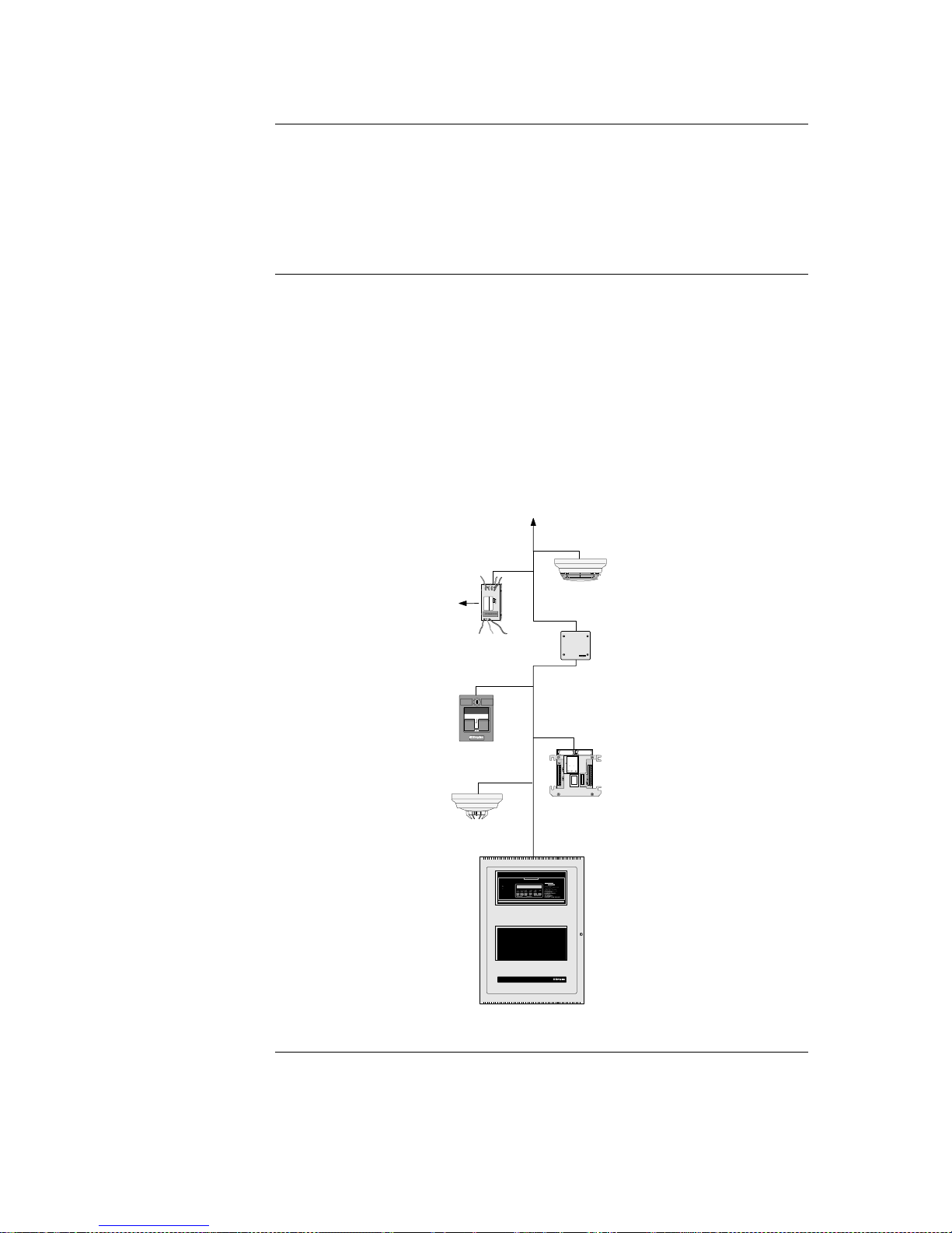
All appliances and devices are connected to this one cabinet, as shown in Figure 1-1.
ALARM
FIRE
PULL
Addressable
station
I/O Module
Supervised IAM
Smoke sensor
with base
Remote line
powered isolator
To additional IDNET devices, up to 250 total
4100
FIRE ALARM CONTROL
PULL TO OPEN
EMERGENCY
INSTRUCTI
ALARM OR TROUBLE
- SYSTEM INDICATOR
TO
- PRESS "ACK" LOCATED
- REPEAT OPERATION UNTIL
TO SILENCE
- PRESS "ALARM
TO RESTORE SYSTEM
- PRESS
- PRESS "ACK" TO
OPERATO
INTERFAC
PANEL
TROU SILEN O
ALA
SYST
SUPERVI
SYSTEM IS NORMAL
12:35:15 am MON 29 JAN
ACKNO
TB
AC
ALA
SI
M
PL
EX
TI
M
E
21
9091
55
.09
21
9091
57
.01
IN
ST
AL
.
IN
ST
RU
C.
21
9091
61
.04
21
9091
63
.04
IN
ST
AL
..I
NS
TR
UC
.
33
33
BA
UD
RA
TE
28
51
957
1
2
3
4
5
AD
DR
ES
S
1
2
3
4
5
6
7
A
D
D
R
E
S
S
C
51
91 2 3 4 5 6
Thermal sensor
with base
to Device
Figure 1-1. Basic 4100ES-S1 System
Overview
System Design
Page 17

1-3
4100ES-S1 Part Codes
This section lists the parts that are supported by the 4100ES-S1 Fire Alarm System.
The following is a list of assemblies, cards and modules used in 4100ES-S1:
These parts are included in the base 4100ES-S1:
742-516 CPU Motherboard (566-227)
4100-7158 CPU Card (566-719)
4100-9848AU System Power Supply, Australian version
4100-6033 Alarm Relay Card (566-058) plugged onto the SPS and used
to supply the Brigade I/F relays.
PA0915 Fuse Distribution Board, connected to the Auxiliary Power
terminals of the System Power Supply
4100-2300 Expansion Bay Assembly (includes the metalwork with the
PDI back-plane)
4100-1288 64 LED/64 Switch Controller module with mounting plate
4100-1282 8 SW/16 LED red/yellow module (2 off)
These parts may be used to expand a 4100ES-S1:
4100-1282 8 SW/16 LED red/yellow module
4100-3101AU IDNET Module – 250 point capacity
4100-3107AU IDNet+ Module – 246 point capacity, four loops
4100-3204 4 Point Relay Module
4100-3206 8 Point Relay Module
4100-1289 64 LED/64 Switch Controller module
4100-1287 24 Switch/24 red LED module
4100-1284 8 Switch 16 red/green LED module
4100-1281 8 Switch 8 yellow LED module
4100-0160 Internet Interface Module (566-355).
ME0456 Fan Control Module
The following kits are available to install in a base 4100ES-S1:
Brigade Interfaces
FP0935 ASE Door Kit (ASE not included)
FP0937 PPU/AIU Door Kit (PPU/AIU not included)
Other
4100-KT0448 Fused DC Distribution Bd, XSPS AU Mounting
4100-KT0468 4100 Motherboard to 4100U Bay, Mounting Kit
4100-0766K T-GEN 50 and 4100U Mounting Bracket Kit
ME0460 T-GEN 50 Evacuation Control Switch and Label
ME0490 T-GEN 50/4100U Dynamic Microphone and lead
Continued on next page
Overview
Assemblies, Cards &
& Modules
Kits
Page 18

1-4
4100ES-S1 Part Code, Continued
LB0602 Operator I/F ISO/Test Card
LB0605 Fan Control Zone Insert Card
526-873 Slide In Label, LED Switch Module, 1 Sheet of 6
4100-1294 LED Module Slide In Labels, Panel Set
LM0309 4100U Mains Lead With Filter
LM0310 4100U Battery Lead Set, 18U-21U
734-008 Harness, Power Comms, 4 Way, 2ft Length
734-075 Harness, Power Comms, 4 Way, 8ft Length
116-226 Sw/LED Module Ribbon Cable, 26 Way, 2in
116-227 Sw/LED Module Ribbon Cable, 26 Way, 6in
The following is a list of existing 4100+/A/U cards and modules that may be used with
4100ES-S1.
4100-5004 8 AZF Monitor Zone
4100-0113 Dual RS232 Modem Interface
4100-3003 8 Relay Module
4100-4321 6 Supervised Relays
4100-3024 24 Relay Module
4100-0302 24 I/O Module
4100-0111 Quad Isolator Module
4100-6078 Modular Network Card (requires 2 media cards)
4100-6056 Wired Media Card RS485
4100-6057 Fibre Optic Media Card
4100-0154 VESDA High Level Interface
Labels
(expansion/spares)
Looms
(expansion/spares)
4100 Part Codes (Non-4100ES)
Page 19

1-5
Glossary
AZF Alarm Zone Facility – means of grouping multiple detectors or devices,
and providing common indication and control.
Class A Wiring Method of connecting multiple devices or units in a loop. This requires
up to twice as much wire but means that a short or open circuit in any
one section will not prevent communication with every device.
Class B Wiring Connection of multiple devices sequentially, or with spurs, uses the
minimum amount of cable, but a single wiring fault can affect all
devices at once.
FIP Fire Indicator Panel – usually abbreviated to “panel”.
GPO General Power Outlet – mains power socket.
IDNet Individual Device Network – latest generation of Simplex analogue
addressable devices and the 2-wire loop that connects them.
MAPNet Multi-Application Peripheral Network – an earlier version of
addressable device communication superseded by IDNet. Some
MAPNet devices can be used on IDNet loops.
NAC Notification Appliance Circuit – switched DC output, usually with
supervision for powering notification appliances and warning system
devices.
NIC Network Interface Card – provides network communications between
multiple 4100/4100ES panels.
PDI Power Distribution Interface – the backplane power distribution system
used in 4100ES.
PID Product Identification (part number).
RUI Remote Unit Interface – 2-wire communications loop used to connect
4100/4100ES master panels with slave transponders.
SPS System Power Supply – the main 4100ES power supply and battery
charger module. Also includes an IDNet loop port, three NAC outputs,
and the brigade relay card.
Page 20

1-6
Page 21

2-1
This chapter describes how to mount the 4100ES-S1 cabinet to a wall, and how to mount
system card bays into the cabinets, modules to bays, etc.
Most of a 4100ES-S1 is already assembled within the factory. Steps 2 to 6 below are
therefore not typically required in the field, but are included for reference.
The assembly drawings are included in the appendix of this manual for reference.
Refer to the page number listed in this table for information on a specific topic.
Topic
See Page #
Introduction to 4100ES-S1 Cabinet
2-2
Step 1. Mounting Cabinets
2-9
Step 2. Mounting Card Bays to Cabinets
2-9
Step 3. Configuring Cards
2-9
Step 4. Interconnecting Modules and Bays
2-11
Step 5. Installing Modules into Expansion Bays
2-13
Step 6. Installing LED/Switch Modules into Expansion Bays
2-17
4100ES Fan Control Module
2-22
Chapter 2
Installing 4100ES-S1 Components
Introduction
In this Chapter
Page 22

2-2
The 4100ES-S1 cabinet contains the CPU, operator interface, system power supply (SPS),
backup batteries, and any additional modules that the panel requires.
These items are organized into sub-assemblies called bays or card frames, each with a
swing-down front door. The 4100ES-S1 has two bays: the CPU bay and one expansion
bay.
In the standard 4100ES-S1, the CPU bay contains the SPS and the CPU Motherboard
with CPU Daughter card. The front of the bay holds the Operator Interface, consisting of
the LCD, keyboard, and fault sounder. Older 4100-style motherboards can be mounted in
the CPU bay.
The expansion bay has a PDI (Power Distribution Interface) backplane into which can be
plugged a number of 4” x 5” 4100ES modules. Older 4100-style motherboards can also
be mounted in the expansion bay.
Continued on next page
Introduction to 4100ES-S1 Cabinet
Overview
Bays
Page 23
2-3
Introduction to 4100ES-S1 Cabinet, Continued
The 4100ES CPU motherboard (see Figure 2-1) holds the CPU card, which is central to
the 4100ES-S1 system. It is mounted in the CPU bay, occupying two slots of space
immediately beside the power supply. This board does not have a card address DIP
switch (the CPU is always address 0).
Figure 2-1. CPU Motherboard (566-227)
Continued on next page
CPU Motherboard
RUI TERMINAL BLOCK (TB2)
NETWORK WIRED MEDIA/ RS-232
TERMINAL BLOCK (TB3)
POWER/COMM TO
SYSTEM POWER
SUPPLY (P1)
RUI CLASS A
TROUBLE (LED1)
RUI PRIMARY SHORT
TROUBLE (LED2)
RUI SECONDARY
SHORT TROUBLE
(LED3)
BUS CONNECTOR
(J1) (Reserved for
future use)
POWER/COMMS TO
ADJACENT BAY (P4)
POWER/COMMS TO
ADJACENT BAY (P5)
POWER/COMMS TO
ADJACENT BAY (P6)
NETWORK WIRED MEDIA/ RS-232
TERMINAL BLOCK (TB1)
HEADER CONNECTOR TO
OPTION MOTHERBOARD
(P3)
CPU DAUGHTER CARD
CONNECTOR (J3)
POWER CONNECTOR TO
OPTION MOTHERBOARD
(P7)
COMMS CONNECTOR TO
OPTION MOTHERBOARD
(P8)
NETWORK DAUGHTER CARD
CONNECTOR
(J2)
RUI COMM
EARTH SHIELD
JUMPER (P9)
RS-232/NETWORK
CARD PORT 1
JUMPER (P10)
RS-232/NETWORK
CARD PORT 2
JUMPER (P11)
XMIT RTS RCV CTS GND
RUI RUI SHLD RUI RUI
B+ B- A+ A-
1 1 5
5
XMIT RTS RCV CTS GND 24C RSRVD
PIEZO
1
8
Page 24
2-4
Introduction to 4100ES-S1 Cabinet, Continued
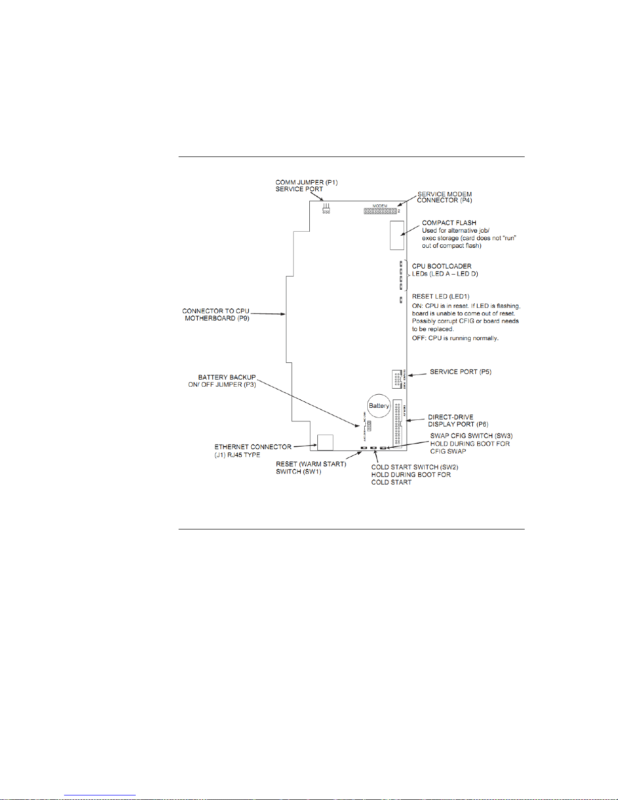
The CPU card (see Figure 2-2) mounts onto the CPU motherboard. The CPU card
contains an Ethernet service port, a direct drive user interface connection, and a serial port
for a service modem.
Figure 2-2. CPU Card (566-719)
Continued on next page
CPU Card
Page 25

2-5
Introduction to 4100ES-S1 Cabinet, Continued
The CPU card LEDs indicate Bootloader status as shown in Table 2-1.
Table 2-1. CPU Card LEDs 1 through 4
Status
Condition
LED D
LED C
LED B
LED A
Bootloader
Initialization
On (0.25s),
Off (0.25s)
On (0.25s),
Off (0.25s)
On (0.25s),
Off (0.25s)
On (0.25s),
Off (0.25s)
Bad Master
CRC or No
Master Present
On
Off
Off
Off
Diagnostic Fail –
RAM
On
Off
Off
On
Diagnostic Fail –
Bootloader CRC
On
Off
On
Off
Downloading
Master
On
Off
On
On
Downloading
CFIG
On
On
Off
Off
Downloading
MsgLib
On
On
Off
On
Downloading
BootLoader
On
On
On
Off
Download
Successful
On
On
On
On
Continued on next page
CPU Card LEDs
Page 26
2-6
Introduction to 4100ES-S1 Cabinet, Continued
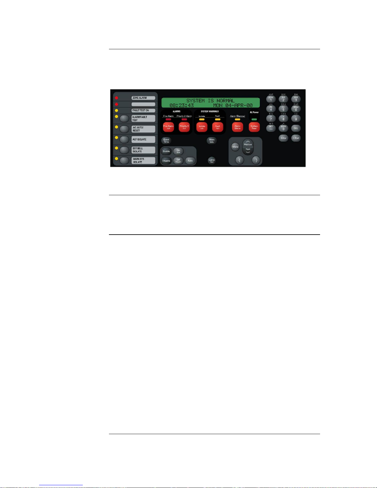
The operator interface (see Figure 2-3) lets a user operate the panel. It provides alarm,
fault, and isolate status alerts, and lets the user review historical logs and perform
diagnostics.
Figure 2-3. Operator Interface
4100-6014 Modular Network Interface Card (NIC). A daughter card that mounts to the
CPU motherboard. Performs 4100 networking operations. May be installed with 41006056 Wired Media Cards and/or the 4100-6057 Fibre Media Cards.
The 4100ES-S1 is powered by the SPS (System Power Supply), which gets its primary
power from the AC mains and its secondary power from the backup batteries.
The SPS in the 4100ES-S1 has hardware and software that are specific to Australian
requirements.
The system power supply is mains powered and has backup batteries that get switched in
on mains failure. It is the initial power source for the CPU and the host cabinet. The SPS
provides 24V card power to the CPU motherboard and the other cards. It also supplies
24V power on a separate bus to the outputs, e.g. Notification Appliance Circuits (NACs).
The SPS also has three on-board NACs that support reverse polarity supervision. It
provides an IDNet channel, auxiliary power, an auxiliary relay, and it mounts and drives
the Alarm Relay Card.
The SPS performs functions such as brownout detection, battery transfer, battery
recharge, earth fault detection, and power limiting of outputs. It provides voltage and
current information to the CPU card, which can then be displayed at the user interface.
The 24VDC bulk power on the SPS is unregulated, and is divided into three feeds: 24V
Card, 24V Signal, and 24V Aux Power. 24V Card, which supplies the cards, and Aux
Power, which is accessible on screw terminals, are each rated at 2A and protected by a
PTC. The 27.3V regulated battery charger is powered from the bulk supply and is
switched off during alarm. The charger has two programmable options of rating: 1.4A for
6-18Ahr batteries, and 3.3A for batteries above 18Ahr.
The “heavy” 24V Signal feed is only accessible via the NACs on the SPS.
Continued on next page
Operator Interface
Additional CPU
Motherboard
Modules
System Power
Supply (SPS)
Page 27
2-7
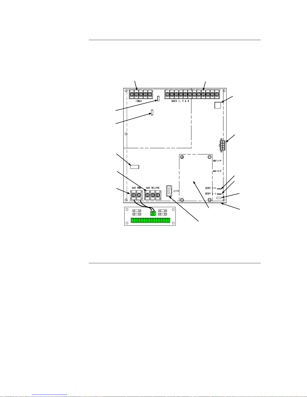
Introduction to 4100ES-S1 Cabinet, Continued
The basic 4100ES-S1 has a Fuse Distribution Board mounted on the SPS chassis and
connected to the Auxiliary Power terminals. See Figure 2-4. This provides four sets of
supply terminals, each individually fused at 1A, but the collective capacity is still limited
to 2A from the Auxiliary Power supply. The fuses are not directly supervised.
Figure 2-4. System Power Supply
Continued on next page
ALARM RELAY CARD
MOUNTING
AREA
ALARM RELAY
CARD
CONNECTOR
AUXILIARY RELAY
TERMINAL BLOCK
(TB4)
AUXILIARY POWER
TERMINAL BLOCK
(TB3)
AC
CONNECTOR
(under board)
BATTERY
CONNECTORS:
P4
P5
POWER/COMM TO
CPU
MOTHERBOARD
(P8)
DEVICE ADDRESS
SWITCH (SW1)
IDNET SHIELD JUMPER
(P2)
CITY/RELAY CARD
TROUBLE INDICATION
JUMPER (P3)
EARTH
FAULT
MONITOR
JUMPER (P1)
NAC TERMINAL BLOCK (TB2)
IDNET TERMINAL BLOCK (TB1)
POWER/COMM TO
NEXT PDI (P6)
24 V IN
+-+-+-+-+-+-+-+
-
F4 F1F3 F2
FUSE DISTRIBUTION BOARD
Page 28
2-8
Introduction to 4100ES-S1 Cabinet, Continued
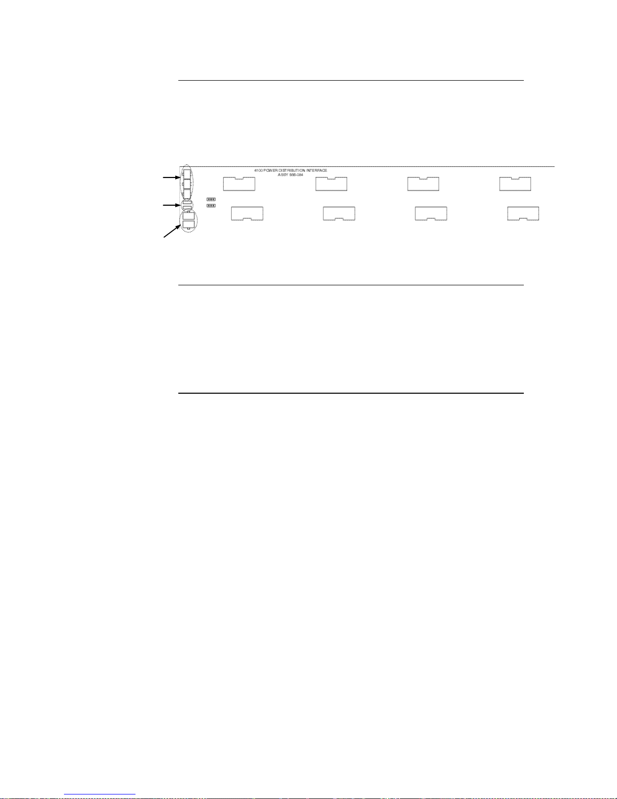
In the expansion bay, power and data are distributed via the power distribution interface
(PDI). The PDI is a wiring board (see Figure 2-5) with eight card slots, each of which can
accommodate a 4-inch (102 mm) x 5-inch (127 mm) slave card. If 4100-style
motherboards are used, they must be mounted over the PDI using a kit of metal standoffs
(part number 4100-KT0468).
Figure 2-5. The Power Distribution Interface (PDI)
The rightmost 2” slot in the expansion bay is occupied by a mounting bracket holding a
single switched General Power Outlet (GPO). The fixed AC power wiring must be
installed to this GPO by a suitably qualified electrician.
IMPORTANT: AC power must be provided to the 4100ES-S1 from a dedicated branch
circuit.
The SPS plugs into this GPO, and can be switched off or unplugged for servicing.
The Power
Distribution
Interface (PDI)
Mains Outlet
POWER/COMMS
CONNECTORS
(P1-P3)
AUDIO INTERFACE
CONNECTORS
(P6, P7)
(Not used in 4100U-S1)
POWER SOURCE
JUMPERS
(P4, P5)
Page 29

2-9
Step 1. Mounting Cabinets
The important aspects of mounting the cabinet are:
Access for the operator;
Height of displays and controls;
Free space for door opening;
Cable entry for field wiring.
Refer to AS 1670.1 for the height requirement and minimum access requirements.
In general, 4100ES-S1 cabinets will be wall mounted. There are four dimpled mounting
holes in the rear of the cabinet. These are accessible from the inside of the cabinet with the
equipment bays still fitted, but it may be more convenient to remove the CPU bay. See the
instruction in the next section about this procedure.
Mounting hole and cabinet dimensions are shown in drawing 1976-176, in the appendix to
this manual.
Door opening is to the left as standard.
The CPU Bay and the Expansion Bay are both attached to the rear of the cabinet by four
8/32” screws. The bays are prevented from movement during transit by locking screws
fitted just below the upper mounting screws.
To remove a bay, remove the locking screws, loosen the mounting screws, then lift the
bay up and out. Disconnect any wiring from the bay before lifting it free.
Assembly is the reverse of this procedure. The transit locking screws do not have to be
re-fitted to an installed cabinet.
The CPU, SPS, and all other modules to be mounted in the 4100ES-S1 cabinet must be
configured to operate correctly in the system via their DIP switch and jumper ports. This
section describes the hardware configuration for the CPU and SPS, since they will always
be used in the CPU bay.
The CPU motherboard must be jumpered as follows:
P9 determines whether the RUI SHIELD signal is connected to 24 C or Earth.
Position 1 – 2: SHIELD to 24 C (default). Set to this position unless the system
uses a TrueAlert Power Supply. Use this setting for 4100ES-S1.
Position 2 – 3: SHIELD to Earth. Set to this position only if the system uses a
TrueAlert Power Supply.
Continued on next page
Overview
Step 2. Mounting Card Bays to Cabinets
Overview
Step 3. Configuring Cards
Overview
CPU Motherboard
Configuration
Page 30

2-10
Step 3. Configuring Cards, Continued
Note: Some devices that connect to RUI have inherently grounded shield
terminals, in which case 24 C cannot be used. If 24 C is used, a Negative
Ground Fault will occur.
P10/P11: P10 is associated with Port 1 and P11 is associated with Port 2. P10 and P11 are
used to set the CPU motherboard up to be attached to either a network card or a RS232/2120 card.
Position 1 – 2: Network card (NIC) plugged into CPU motherboard (default).
Position 2 – 3: RS-232/2120 card plugged into CPU motherboard.
The CPU daughter card must be jumpered as follows:
P1 is used for engineering diagnostics (COMLAB). Normally has no link fitted.
Position 1 – 2 : Download or no connection.
Position 2 – 3 : Diagnostic mode.
P3 configures the RAM battery as ON or OFF.
Position 1 – 2 : ON – move to this position for normal operation.
Position 2 – 3 : OFF – factory setting.
The SPS must be configured as follows:
SW1: Using DIP switch SW1, set the SPS card address to 1. Use the address table in
Appendix A for the switch settings.
P2: P2 configures the IDNet shield connection.
Position 1 – 2 (bottom) : Connects the shield to 0 V (default). Use this setting for
4100ES-S1.
Position 2 – 3 (top) : Connects the shield to earth ground.
P3 configures relay 3 on the 4100-6033 Alarm Relay Card.
Position 1 – 2 (top) : Removes fault monitoring on Relay 3 (default). Use this setting
for 4100ES-S1.
Position 2 – 3 (bottom) : Makes Relay 3 activate when there is a fault.
P1: Earth connect jumper.
Position 1 – 2 (rhs): Enables Earth fault monitoring. Set to this position unless the
system uses a TrueAlert Power Supply under common 0 V. Use this setting for
4100ES-S1.
Position 2 – 3 (lhs): Disables Earth fault monitoring. Set to this position only if the
system uses a TrueAlert Power Supply under common 0 V.
P4/P5: The PDI can be configured to draw its power from different sources via P4 and
P5. For 4100ES-S1 both links should be in position 1-2.
Refer to the appropriate installation instructions to configure other cards that are located
in the CPU and expansion bays. The common 4100ES cards and modules are included in
this manual. Refer to Appendix D for a list of publications.
CPU Daughter Card
Configuration
SPS Configuration
PDI Configuration
Configuring Other
Cards
Page 31

2-11
Step 4. Interconnecting Modules and Bays
Each card has to be interconnected with every other card in its bay. At the same time,
bays in the 4100ES-S1 also have to be connected together. Read this section to ensure
that cards and bays are interconnected correctly. Refer also to drawings 1976-136 and
1976-137.
The basic 4100ES-S1 will have all necessary interconnection wiring already fitted, but
additional wiring may be necessary if expansion modules are fitted.
Review the following guidelines before interconnecting modules and bays.
The SPS provides 24 V power to the CPU motherboard.
The CPU motherboard provides 8 V (3 A capacity) for use by legacy 4100 slave
cards. 24 V Card power is routed through the motherboard for slave card use.
4100 internal comms and power are harnessed to other bays. Do not connect the 8 V
at P7 to an 8 V converter on a Goldwing or remote interface card.
24 V Card power from the SPS is rated at 2 A maximum.
The 4-wire comms and power harness carries only the 24 V Card supply to a PDI,
and not the 24V Signal supply.
Some of the wire harnesses supplied with add-on cards may not be required. These
spare harnesses should be stored in case of future requirements.
Connect P8 on the SPS to P1 on the CPU motherboard using the 8 wire harness with
eight-position Molex minifit connector (provided).
The power distribution interface (PDI) mounted to the back of the expansion cabinet
carries 24V Card power and data to each 4”x 5” card.
Refer to “Step 5: Installing Modules into Expansion Bays for instructions on mounting
4”x 5” cards to the PDI. Also bear in mind that legacy 4100 motherboards require non-
PDI interconnections to each other and to the CPU Motherboard.
The 4 wire harness 734-008 is used to carry 24V Card power and coms from the CPU bay
to the expansion bay. Connector P1 on the PDI receives power from P6 on the SPS or P7
or P8 on the CPU Motherboard. P2 on the PDI is used to connect power and comms to a
64/64 Controller. In a larger system, P3 on the PDI is used to carry power and comms to
the next PDI, but is not used in 4100ES-S1.
Continued on next page
Overview
Guidelines
Card
Interconnections in
the CPU Bay
Card
Interconnections
Within Expansion
Bay
Basic Bay-To-Bay
Interconnections
Page 32

2-12
Step 4. Interconnecting Modules and Bays, Continued
Panels with legacy motherboards in the expansion bay require some non-PDI
connections. If you need to connect a harness to a motherboard, refer to Figure 2-6 and
follow these steps. Make sure to route the power and communication wiring on the left
side of the bay.
1. Connect one end of the 733-525 Harness to a motherboard in the CPU bay.
If the CPU bay has no additional motherboards (the usual case), connect the harness
to the P8 and P7 connectors of the CPU motherboard.
Insert the harness connector with the blue wire into the P8 connector. Note that
the P8 connector has eight pins. Insert the harness connector on either the top
four pins or the bottom four pins, not in the middle.
Insert the harness connector with the white wire into the P7 connector. Note that
the P7 connector has eight pins. Insert the harness connector on either the top
four pins or the bottom four pins, not in the middle.
2. Connect the other end of the harness to the leftmost motherboard in the next bay,
as described below.
Insert the harness connector with the blue wire into the P2 connector. Note
that the P2 connector has eight pins. Insert the harness connector on either
the top four pins or the bottom four pins, not in the middle.
Insert the harness connector with the white wire into the P3 connector. Note
that the P3 connector has eight pins. Insert the harness connector on either
the top four pins or the bottom four pins, not in the middle.
Figure 2-6. Power and Communication Wiring for Motherboards (note that there
are limitations of where motherboards can be placed – see next section)
Connecting to
Motherboards
Connector with
Blue Wire Goes
to P2
Connector with
White Wire Goes
to P3
733-525 Harness
Page 33

2-13
Step 5. Installing Modules into Expansion Bays
This section contains guidelines and instructions on installing 4”x 5” cards and traditional
motherboards into the 4100ES-S1 expansion bay.
IMPORTANT: This section applies to aftermarket modules for expansion bays only. If
you do not need to install any aftermarket modules at all, you have
completed the panel installation and can apply AC power.
Refer to the following guidelines before mounting 4” x 5” cards and/or motherboards to
the expansion bay.
The expansion bay assembly includes a chassis, two end supports, one LED/switch
frame, and a power distribution interface (PDI) board.
An expansion bay holds up to four 4” x 5” modules if a T-GEN 50 is fitted, or up to
six modules if not. See Figure 2-7.
Figure 2-7. Expansion Bay 4”x 5” Card Placement
Continued on next page
Overview
Placement
Guidelines
Power Distribution Interface (PDI)
I/O Wiring
4" x 5" Module
Block A Block C Block E
Block B Block D Block F
Slots 7 & 8
I/O Wiring
4" x 5" Module
I/O Wiring
4" x 5" Module
I/O Wiring
4" x 5" Module
Main Outlet (GPO)
Mounting Bracket
T-Gen 50 on mounting bracket (if fitted)
(heatsink intrudes into slot 6 space)
Page 34

2-14
Step 5. Installing Modules into Expansion Bays, Continued
Motherboards can be installed on top of the PDI in expansion bays. The data and
power that would normally be bussed via the PDI are routed across the motherboards
via their left and right connectors (J1 and P1).
Up to four 2” (51 mm) x 11 ½” (292 mm) motherboards can be installed in an
expansion bay if the pins on the left connector (usually P1) on the leftmost
motherboard are removed. See Figure 2-8.
Motherboards should be added from left to right, starting in slot 3.
Relay motherboards must be the rightmost motherboards.
The CPU motherboard generates the 8V supply required for 4100A motherboards. It
also has the 4100A style Molex connectors to which a harness can be fitted as in
Figure 2-6.
Power Distribution Interface (PDI)
Block A Block E
Block B Block F
Slots 7 & 8
I/O Wiring
4" x 5" Module
Main Outlet (GPO)
Mounting Bracket
T-Gen 50 on mounting bracket (if fitted)
(heatsink intrudes into slot 6 space)
4100 Option
cards cannot be
fitted in these
slots because of
clashes with the
front panel
display
controllers
Figure 2-8. Expansion Bay Motherboard Placement
Continued on next page
Placement
Guidelines
(continued)
Up to four 2” x 11 ½” motherboards can be mounted in the
expansion bay. Three motherboards fit into Slots 3 through 5; the
fourth can be added in Slot 6 if a T-GEN 50 is not fitted.
Page 35

2-15
Step 5. Installing Modules into Expansion Bays, Continued
The power distribution interface (PDI) is mounted to the back of the expansion bay. See
Figure 2-9. The PDI contains slots for up to eight 4”x 5” slave cards. Since the PDI
carries power and data across the entire bay, it solves most interconnection issues,
especially between 4”x 5” cards.
Use the following instructions and the figure below to mount 4”x 5” slave cards to the
expansion cabinet.
1. Screw two standoffs and washers to the appropriate holes in the back of the
cabinet. These holes must line up with the screw holes in the 4”x 5” card. See
Figure 2-9.
2. Plug the 4”x 5” card into the appropriate blind mating connector. Seat the card
firmly onto the PDI when installing to ensure complete insertion of the power
connector into the PDI.
3. Secure the other end of the card to the standoffs with two 6/32” x ¼” torx screws
and washers.
Figure 2-9. Slave Card/PDI Connection
Continued on next page
Installing 4” X 5”
Cards
4”x 5” CARD
STANDOFFS
6/32”
SCREWS
WASHERS
PDI CONNECTOR
(reverse side)
PDI
SCREW
RETAINERS
Page 36

2-16
Step 5. Installing Modules into Expansion Bays, Continued
Use the following procedure when installing motherboards in an expansion bay. Start
with the third slot from the left and fill to the right. The mounting items are available as
kit 4100-KT0468.
1. Orient the motherboard with the connector labeled J1 on the right and the header
labeled P1 on the left.
2. Attach four metal threaded standoffs and lockwashers into the screw holes on the
chassis.
3. Attach two grey plastic standoffs to the motherboard socket mounting screws.
4. Secure the motherboard to the standoffs using four #6 torx screws as shown below.
Figure 2-10. Installing the Motherboard in a 4100ES-S1 Expansion Bay
Figure 2-10 shows the motherboard being fitted to slot 2. In 4100ES-S1, slots 1 and 2
can‟t be used for motherboards.
Installing
Motherboards
#6 SCREWS
LOCKWASHERS
METAL
STANDOFFS
SCREW HOLES
SCREW HOLES
PLASTIC STANDOFFS
Page 37

2-17
Step 6. Installing LED/Switch Modules into Expansion Bays
The LED/switch user interface consists of a variety of modules, mounted to the front of
an expansion bay, which are configured via the 4100ES Programmer. Each display
module contains between 8 and 24 switches and LEDs, each one separately configurable.
User interface functionality is driven by the 64/64 LED/Switch Controller Card, which
mounts behind two of the display modules (in positions 1 and 2). The types of modules
typically used in 4100ES-S1 are as follows:
4100-1288 LED/Switch Controller Card with mounting plate.
4100-1289 LED/Switch Controller Card (no mounting plate; it mounts on the
expansion space of 4100-1288).
4100-1282 Display Card. With one red and one yellow LED per switch, this is
used for Alarm Zone Facility displays.
4100-1294 Slide-In Label Kit - one per 4100ES-S1 cabinet
ME0456 Fan Control Module
Each 4100-1288 or 4100-1289 LED/switch controller supports up to 64 LED indicators
and 64 switch controls. Using the 4100-1282 Display Card for zone displays, this
corresponds to 32 zones per controller.
Other display cards are available for special display functions. Special configuration is
required to use other display cards. Contact your Simplex dealer for guidance.
Continued on next page
Overview
Page 38

2-18
Step 6. Installing LED/Switch Modules into Expansion Bays, Continued
Figire 2-11shows an LED/switch bay from the user‟s perspective.
Figure 2-11. LED/Switch Modules
The LED/switch controller card is a 4100 slave that mounts behind two LED/switch
modules. Each LED/switch controller handles up to 64 switches and 64 LEDs on the
modules and communicates their status to the 4100ES CPU. This is sufficient for 32
zones.
Figure 2-12. LED/Switch Controller
The standard configuration of 4100ES-S1 uses 4100-1282 cards for zone displays, with
programming so that pressing any switch toggles the Isolate state of the corresponding
zone.
Continued on next page
The LED/Switch
User Interface
LED/Switch
Controller Card
LED/SWITCH DISPLAY
CONNECTOR
(P4; reverse side)
POWER/COMMS
CONNECTORS
(P2)
(P3)
COMM LOSS LED
(LED1)
ADDRESS DIP
SWITCH (SW1)
REMOTE ANNUNCIATOR
JUMPER (P1)
Page 39

2-19
Step 6. Installing LED/Switch Modules into Expansion Bays, Continued
If more than 32 zones are required, a second controller (4100-1289) will be required.
Note that an ME0456 fan control module counts as 8 zones when adding up the controller
requirements.
LED 1. This LED illuminates if communication loss between the controller and the CPU
occurs. It is independent of jumper P1 (which configures different communication loss
features).
The 64/64 LED/switch controller requires physical configuration, but the LED/Switch
modules do not. Switch controller configuration consists of setting jumper P1 and setting
the card address. See Figure 2-12. In the 4100ES-S1, the first display controller is
address 3 and the second has address 4. Card addressing is covered in Appendix A.
Refer to Figure 2-13 to mount the display cards to the front of the expansion bay.
Figure 2-13. LED/Switch Card Mounting
Continued on next page
LED/Switch
Controller Card,
(continued)
Configuring the
LED/Switch
Controller Card
Mounting
LED/Switch Modules
to the Expansion
Bay
#6 UNC NUTS
GROUND
CONNECTION
ADDITIONAL
LED/SWITCH
CONTROLLER
GROUND
CONNECTION
LOCKWASHERS
LED/Switch Controller
assemblies are installed
in the end slot in the
basic 4100U-S1
Page 40

2-20
Step 6. Installing LED/Switch Modules into Expansion Bays, Continued
Refer to Figure 2-14 and the instructions below to mount the LED/switch controller card
assembly to the back of one of the LED/switch cards.
1. Use four 322-123 nuts and four 268-009 bay washers to secure the 637-141
bracket to the inside front of the expansion bay. Note that there is only one
location where the bracket can be mounted, as shown in Figure 2-13.
2. Attach the header connector on the back side of the controller (P4) to the P1 (In)
connector on the back side of the first LED/switch modules.
3. Secure the controller card to the board using four 6/32” x 1/4 “ Torx screws, as
shown in Figure 2-14.
Figure 2-14. Controller Card Mounting
The second Controller Card (4100-1289) is mounted in the spare space on the same
bracket.
Continued on next page
Mounting the
Additional LED/
Switch Controller
Card
Page 41

2-21
Step 6. Installing LED/Switch Modules into Expansion Bays, Continued
All types of modules are mounted to the front of a bay, and are connected to each other
via a ribbon cable. Each module operates by the same rules: when a button is pressed, the
controller card sends the CPU the information, and the action programmed for that button
occurs.
To interconnect display cards and connect the controller card to a power source:
1. Use harness 734-008 to connect P2 on the controller card to one of the 4-pin
connectors on the PDI. See Figure 2-15.
2. If there are two controller cards, use harness 734-036 to connect P3 on the first
controller card to P2 on the second controller card. The order does not matter.
Connect P4 of the controller to P1 of the left-most display module, with the ribbon cable
provided (the first two display modules are fitted in the factory). Connect P2 of this
display module to P1 of the next module, up to a maximum of four modules. Repeat for
the second controller, if fitted.
TO PDI
CONNECTOR OR
ANOTHER
CONTROLLER
CARD
26 - CONDUCTOR
RIBBON CABLE
734HARNESS 008
TO SECOND
CONTROLLER CARD
OUT
P2
IN
P1
LED/SWITCH
MODULE 1
OUT
P2
IN
P1
LED/SWITCH
MODULE 2
OUT
P2
IN
P1
LED/SWITCH
MODULE 3
OUT
P2
IN
P1
LED/SWITCH
MODULE 4
LED/SWITCH
CONTROLLER
(reverse side)
P4
HARNESS
734-008
Figure 2-15. LED/Switch Controller Wiring
(approximately as viewed on the rear of the open bay door)
LED/Switch Modules
Wiring Instructions
Page 42

2-22
4100ES Fan Control Module
The ME0456 is a 4100ES style Switch/LED display module designed specifically for fan
control. It complies with the requirements of AS 1668.1:1998. It has rotary switches and
LEDs for 4 sets of fans. In order to accommodate the required rotary switches, the front
plate is joggled forward so that it protrudes through the trim.
The Fan Control switch positions of ON, AUTO and OFF, are permanently marked on the
faceplate label, as required by AS 1668. The name area accommodates 3 rows of 6 letters
at 5mm.
The labelling of the LEDs, ON, FLT, and OFF is marked on the removable fan name
label card, LB0605, supplied with the module.
The card may be reversed and different LED labelling used, e.g. for damper controls.
A template version of this label is available as LB0605. This template allows entry of the
fan name on a PC for local printing. LED names may also be revised.
The Fan Control module mounts to the frame of the 4100ES-S1 Expansion bay door from
the front, in a similar fashion to display modules. Mounting nuts and washers are
provided.
Connection from “Out” of the adjacent Switch/LED module (or 64/64 Controller if it is
the first module on that Controller) to “In” on the module is by the flat flexible cable
provided (166-226).
The module is programmed as a standard 8 Switch/16 LED module. Up to four modules
can be driven by one 64/64 Switch/LED Controller.
Each fan control with one rotary switch uses two of the 8 “switches”, and 3 of the 16
LEDs of an 8 Switch/16 LED module as per Table 2-2. The other 4 LEDs are not fitted so
must not be programmed, since it serves no purpose.
Table 2-2. Switch/LED Format
Fan Control
Switches
LEDs
ON
FLT
OFF
1
SW1, SW2
LD1
LD2
LD3
2
SW3, SW4
LD5
LD6
LD7
3
SW5, SW6
LD9
LD10
LD11
4
SW7, SW8
LD13
LD14
LD15
The switch functions for Fan Control 1 are shown in Table 2-3. The state of having both
switches closed is not physically achievable.
Table 2-3. Switch Status
SW1
SW2
Fan Control Status
Closed (up)
Open (centre)
On
Open (centre)
Closed (up)
Off
Open (centre)
Open (centre)
Auto
Continued on next page
Overview
Labelling
Mounting &
Connection
Programming
Page 43

2-23
Figure 2-16. ME0456 Fan Control Module
Page 44

2-24
Installing Other Modules
Detailed installation instructions for these modules can be found in these instruction
documents. A copy of the appropriate document is supplied in the kit with each module.
Table 2-4. Module Installation Documents for 4100ES-S1
Part Code
Description
Installation
Instruction
4100-3101AU
IDNET module provides an additional IDNET loop,
with up to 250 devices.
This is a PDI card.
574-800
4100-3107AU
IDNET+ module provides 1, 2, 3 or 4 additional
IDNET loops with independent fault isolation. The
total number of devices on these loops can be up to
246.
This is a PDI card.
579-786
4100-3003
8 point relay module with 8 input points as well.
Relay outputs are each a single changeover contact
rated at 3A at 30V.
This is a legacy card.
579-220
4100-3204
4 point relay module with 4 input points as well.
Relay outputs are each a pair of changeover contacts
rated at 2A at 30V.
This is a PDI card.
4100-3206
8 point relay module. Relay outputs are each a pair
of changeover contacts rated at 3A at 30V. There are
no feedback inputs.
This is a PDI card.
4100-5004
8 zone module providing 8 conventional detector
circuit interfaces.
This is a legacy card.
579-205
4100-0113
Dual RS-232 serial interface, providing two
independent serial ports for connection printers,
modems, or other 3rd party equipment.
This is a legacy card.
572-221
4100-0154
VESDA High Level Interface. This is a dual serial
interface customized to connect to a VESDA and
communicate compatible status and control
messages.
This is a legacy card.
574-050
4100-0302
24 point Graphic I/O module provides 24
configurable inputs or outputs for direct connection,
e.g., zone displays.
This is a legacy card.
LT0298
4100-3024
24 point Graphic I/O module provides 24
configurable inputs or outputs with relay isolation,
e.g., fan controls, BMS interfaces.
This is a legacy card.
Page 45

3-1
A basic 4100ES-S1 system becomes a network node when a Network Interface Card
(NIC) or other compatible network card is installed and connected to another network
node. How network cards connect to each other depends on the type of media cards being
used.
Refer to the page number listed in this table for information on a specific topic.
Topic
See Page #
Network Configuration
3-2
Introduction to the 4100 Network Interface Card (NIC)
3-4
Step 1. Configuring Network Cards
3-7
Step 2. Mounting Media Cards to the NIC
3-9
Step 3. Mounting Network Cards in the 4100ES-S1
3-9
Step 4. Wiring Network Cards
3-10
Chapter 3
Networking
Introduction
In this Chapter
Page 46

3-2
Network Configuration
Multiple 4100ES-S1 panels can be connected together into a network system by using
network interface cards (NICs). When a NIC is installed into a 4100ES-S1, it is used to
connect to other network nodes. Nodes may consist of other 4100ES-S1 or 4100ES
panels, or they may be other types of node such as Graphic Command Centre (TSW), or
Visual Command Centers (VCCs). A node is a self-sufficient CPU that controls
appliances and devices, and which also has the capability of controlling and
communicating with other nodes.
The network configuration supports two common architectures or wiring configurations:
ring or star. A networked system can also use a combination of the two.
The ring configuration consists of a number of nodes connected in a closed loop. The star
configuration consists of several nodes connected directly to one common node. Physical
bridge cards are used for the star configuration. Physical bridges reduce the amount of
wire that would otherwise be needed to connect all nodes in a loop, and therefore cut
down on system response time. However, the ring configuration is more secure against
cabling faults. A combination of the two styles is illustrated in Figure 3-1.
Ring Topology
Physical Bridge Links
(Star Topology)
Graphic Command
Center (GCC)
Network Display Unit
(NDU) Hub Node
Distributed Remote
Node Locations
Figure 3-1. Ring/Star Configuration Example
Continued on next page
Overview
Ring and Star
Configurations
Page 47

3-3
Network Configuration, Continued
Network rings or loops can be joined via physical bridge cards. There may be no more
than two network loops connected in tandem. For every two loops that are
interconnected (using one physical bridge), there can be a maximum of three other
physical bridges used in a star configuration. See Figure 3-2.
Remote Loop
Physical Bridge Link
Local Loop
Physical Bridging
(Star Configuration)
Graphic Command
Center (GCC)
Physical
Bridge
Link
Physical Bridge Link
Hub Node
Hub
Node
Remote
Node
Physical Bridge Link
Figure 3-2. Interconnected Loop Configuration
To be used as a network node, a 4100ES-S1 panel must contain the following:
CPU
System Power Supply
4100-6014 Network Interface Card plus two Media Cards
Connecting Loops
System Design
Page 48

3-4
Getting Started
This chapter describes how to turn a basic 4100ES-S1 into a network node. This process
consists of the following:
Step 1. Mounting media cards to the network interface card (NIC)
Step 2. Mounting the network cards in the panel
Step 3. Wiring between panels
Each step is described in this chapter. Before beginning the installation, review the next
few pages for a detailed description of network cards and the media cards that mount onto
them.
The Network Interface Card (NIC) is a slave card that uses the standard 4100 serial bus to
communicate with the CPU. The NIC connects 4100ES-S1 and other panels in a network,
providing communication between each panel via fibre or shielded twisted pair cable.
The NIC is designed to be connected in a loop or ring arrangement, so that a single cable
fault does not cause the entire system to fail. The ring arrangement provides the most
secure and fault-tolerant wiring possible.
Two types of media boards can be used with the NIC card.
The Fibre optic Media Card uses multimode optical fibres to connect network
nodes. This can be used for electrically noisy environments or for connecting
externally to other buildings.
The Wired Media Card is used in all other types of applications. This uses
ordinary screened paired cable to connect network nodes.
Up to two media boards can be plugged onto each NIC. The same NIC can use a
combination of two types of media boards (for example, a NIC may have a wired media
card connected to port 1 and a fibre optic media card connected to port 2).
Continued on next page
Overview
Introduction to the 4100 Network Interface Card (NIC)
Overview
Page 49

3-5
Introduction to the 4100 Network Interface Card (NIC), Continued
Figure 3-3. 4100-6014 Network Interface Card
The 4100-6014 NIC has the following LEDs:
LED1 (yellow). Illuminates when
The host CPU requests it to illuminate
A transmission fails
It is off-line with the host CPU
It needs to be configured
LED2 (red). Illuminates when a data „0‟ is received at the right port.
LED3 (green). Illuminates when a data „0‟ is transmitted at the right port.
LED4 (red). Illuminates when a data „0‟ is received at the left port.
LED5 (green). Illuminates when a data „0‟ is transmitted at the left port.
Continued on next page
Network Module
Illustrations
NIC Card LED
Indications
Page 50

3-6
Introduction to the 4100 Network Interface Card (NIC), Continued
There are two media cards that can be plugged into the 4100-6014 NIC:
4100-6057 Fiber-Optic Media Card (565-261)
4100-6056 Wired Media Card (565-413)
Each module is shown below.
Figure 3-4. The 4100-6057 Fiber-Optic Media Card
RESERVED (TB1)
Figure 3-5. The 4100-6056 Wired Media Card
Continued on next page
NIC Media Cards
40-PIN NETWORK
INTERFACE CARD
CONNECTOR (J1)
FIBRE OPTIC DATA:
TRANSMIT (U1),
RECEIVE (U2)
40-PIN NETWORK
INTERFACE CARD
CONNECTOR (P1)
Page 51

3-7
Introduction to the 4100 Network Interface Card (NIC), Continued
Table 3-1. 4100 NIC & Media Cards - Electrical and Environmental
Specifications
Electrical Specifications
Network
Interface Card
Startup, no media cards: 8 VDC @ 110 mA
Nominal, no media cards: 20 to 32 VDC @ 0 mA
Fiber
Media Card
Using 24 V power supply: 20 VDC @ 140 mA max.
Using 5 V power supply (GCC/NPU): 5 VDC @ 130 mA max.
Wired
Media Card
4.75 to 5.25 VDC @ 170 mA max.
Environmental Specifications (All Modules)
Operating
Temperature
32 to 120 F (0 to 50 C)
Humidity
10% to 93% relative humidity at 32C
The NIC card, along with each media card, all have jumpers that must be set as shown
below.
NIC-compatible jumper settings on CPU motherboards depend on which motherboard is
used.
Motherboard 566-227 (normally used in 4100ES-S1):
P10: Port 1 settings.
P11: Port 2 settings.
P10/P11 position 1 – 2: Network card (NIC) attached to CPU motherboard (default).
P10/P11 position 2 – 3: RS-232/2120 card attached to CPU motherboard.
Motherboard 565-274:
JW1 and JW2 must be installed.
Jumper plugs P5-P8 must not be installed.
Use SW2 to set the NIC card address. Refer to Appendix A for the address table.
Continued on next page
Requirements
and Limitations
Step 1. Configuring Network Cards
Overview
CPU Motherboard
Jumper Settings
NIC Card
Address Setting
Page 52

3-8
Step 1. Configuring Network Cards, Continued
There are two jumper settings on the NIC card: P3 and P4.
P3: Determines the NIC data transmission rate, 57.6 kbits/second or 9600 bits/second.
Position 1 – 2 (the right two pins) or no pins jumpered: 57.6 kbits/second
(default for 4100ES-S1).
Position 2 – 3 (the left two pins): 9600 bits/second.
P4: Determines the data protocol, 8-bit or 9-bit, that the NIC card is using.
Position 1 – 2 (the right two pins) or no pins jumpered: 9-bit (default for
4100ES-S1).
Position 2 – 3 (the left two pins): 8-bit.
All settings are labelled on the card.
P2: Tells the system which wire type is to be used.
Positions 1 – 2, 5 – 6, and 7 – 8: 0.8mm shielded, twisted pair wiring.
Remove all jumpers to specify 0.2mm unshielded twisted pair telephone cable
wiring.
IMPORTANT: When using the wired media card, the Earth fault detection is performed
on the left port only. Remove R1 (1 Ohm resistor) from the wired media
card on the right port.
NIC Card
Jumper Settings
Wired Media Card
Jumper Settings
Page 53

3-9
Step 2. Mounting Media Cards to the NIC
The 4100-6014 Network Interface Card (NIC) uses media cards to connect to other NICs.
This section describes how the media cards are mounted onto NICs.
NICs connect to each other via the two types of media cards. The types of media cards in
the right and left ports are determined by the type of wiring that is being used between
cards.
Connect P1 on the wired media card, or J1 on the fibre media cards, to P5 (the left port)
on the NIC.
To connect a second media card to the same NIC, connect it as described above, but use
P6 (the right port) on the NIC. Note that any two types of media cards can be connected
to the same NIC.
Figure 3-6. Media Card Mounting
The 4100 NIC daughter card inserts into motherboards as follows:
If the 566-227 CPU Motherboard (default for 4100ES-S1) or 565-275 CPU
Motherboard is used, the NIC daughter card is inserted into connector J2.
If the 565-274 CPU Motherboard is being used, the NIC daughter card is
inserted into connector J1.
Overview
Media Card
Mounting
Step 3. Mounting Network Cards in the 4100ES-S1
MEDIA CARDS
4100-6014 NETWORK
INTERFACE CARD
40-PIN
CONNECTION
(MEDIA CARD
P1 OR J1 TO
NIC P5)
40-PIN
CONNECTION
(MEDIA CARD
P1 OR J1 TO
NIC P6)
STANDOFFS FIT INTO HOLES
Page 54

3-10
Step 4. Wiring Network Cards
The nodes in the network now have to be wired together, so that the NIC in one host
panel connects to the NIC in the next panel.
Refer to the following guidelines field wiring
General
Network nodes must be wired from right port to left port, regardless of the media
type selected.
Best protection is achieved by wiring the nodes in a loop fashion. A single fault
(except an Earth fault) will cause the network to reconfigure for degraded
operation. A second fault (except an Earth fault) will result in the network
dividing into two separate networks.
It is permissible to use mixed media in a network. For example, some spans may
be wired media while others are optical fibre.
Each NIC has a jumper for selecting between network data rates of 57.6 kbps
and 9.6 kbps. All cards in the network must be set for the same rate. When
physical bridging is used, the data rate must be set to 9.6kbps.
Each NIC has a jumper for selecting between 8- and 9-bit network protocols. All
cards in the network must be set for the same network protocol. When physical
bridging is used, the protocol must be set to 9-bit.
Wired Media
Earth fault detection is performed on the left port only. When a network Earth
fault occurs, the trouble is reported on the node whose left port is connected to
the earthed section.
All 0.8mm2 wiring used Wired Media Cards must be shielded twisted-pair. All
0.2mm
2
(telephone cable) used must be twisted pair. When shielded cable is
used, the shield must be terminated to chassis Earth on the left port only.
All network wiring except the shield is supervised and power limited.
When wiring leaves the building, 2081-9044 Overvoltage Protectors should be
connected at the entry point. One overvoltage protector is installed where wiring
leaves the building; another is installed where wiring enters the next building.
Fibre optic
All fibre cables must be multimode, graded index type. ST style connectors must be
used. No physical strain should be put on the cables. There must be no cable bends
of less than a 50mm radius.
Two methods are available for joining fibre cable. Splices provide a permanent, very
low loss, fibre-to-fibre connection. Couplers provide temporary connection between
two ST style connectors with a loss of 1.2dB. Both methods are permitted on a fibre
network.
Maximum line lengths for 50/125 and 62.5/125 cable are shown in Table 3-2.
Overview
Wiring Guidelines
Page 55

3-11
Step 4. Wiring Network Cards, Continued
Maximum wiring distances are shown in Table 3-2.
Table 3-2. Wiring Distances
Media Type
Size
Data Rate
Max Distance
Wired
0.2 mm2
unscreened
twisted pair
57.6 kbps
2,100m
9.6 kbps
3,600m
0.8 mm2
screened twisted
pair
57.6 kbps
3,000m
9.6 kbps
5,200m
Optical Fibre
50/125 um
(4dB/km loss)
57.6 or 9.6 kbps
3,000m
50/125 um
(3dB/km loss)
4,500m
62.5/125 um
(4dB/km loss)
57.6 or 9.6 kbps
4,000m
62.5/125 um
(3.75dB/km loss)
4,600m
Notes:
0.8 mm2 fire-rated screened twisted pair cable must not have more than 190nF/km
capacitance or 21/km resistance.
0.2 mm2 unshielded twisted-pair telephone cable must not have more than 72nF/km
capacitance or 84/km resistance.
Between any two connected network nodes, L+ of one node connects to R+ of the
other, and L- connects to R-.
Continued on next page
Wiring Distances
Page 56

3-12
Step 4. Wiring Network Cards, Continued
Connectors U1 (transmitter) and U2 (receiver) on the 4100-6057 Fiber-Optic Media Card
are used to connect 4100-6014 NICs across parts of a network.
Note: ST connectors with long strain relief boots must be used with the fibre optic
cable.
Dual Fibre Optic Cable Connections. The standard fibre optic connection between
network nodes uses two fibre optic cables, one for transmit and the other for receive. This
connection allows for optimum communications distance.
The available communications distance is determined by the properties of the specific
fibre cable used. Distances can be determined using the information and examples shown
below in Table 3-3.
Between any two connected network nodes, U1 (transmit) on the Fibre Media card of one
node is connected to U2 (receive) of the Fibre Media card of the other node, i.e., the
fibres “cross over” between nodes.
Single Fibre Optic Cable Connections. For applications where a single fibre cable is
available, or where use of a single cable is desired, using a model 4190-9010
Bi-Directional Coupler at each node combines the separate transmit and receive signals
into a single path (refer to the requirements list).
This connection allows use of a single fibre cable, but it does reduce communications
distance as indicated in the information and examples shown below in Table 3-4.
At each node, U1 (transmit) of the Fibre Media card must be connected to the transmit
port of the coupler, and U2 (receive) to the receive port of the coupler.
Continued on next page
Fibre-Optic Wiring
Fibre Optic
Connection Types
Page 57

3-13
Step 4. Wiring Network Cards, Continued
The 4190-9010 Coupler is used with the 4100-6057 Fibre Optic Media Board, revision
“C” or higher. Two 4190-9010 Bi-Directional Couplers are required per connection, one
at each node.
The 4190-9010 is equipped with type ST connectors. To make type ST to type ST
connections, an ST to ST coupler, by others, is required. ST to ST Couplers are available
from:
Black Box, part # FO200
Fiber Instrument Sales, part # F1-8101
Newark Electronics, part # 95F2097
(or equivalent)
Table 3-3. Dual Fibre Optic Cable Communications Distance Examples
Fibre Type 1*
MIFL 2
Power
Margin
Distance 3
Budget 3
50/125
numerical
aperture = 0.2
4 dB/km
4 dB
3 km
17 dB
3 dB/km
3 dB
4.6 km
62.5/125
numerical
aperture = 0.275
4 dB/km
4 dB
4.0 km
21.4 dB
3.75
dB/km
3 dB
4.6 km
*See notes at bottom of page.
Table 3-4. Single Fibre Optic Cable Communications Distance Examples
Using 4190-9010 Bi-Directional Couplers
Fibre Type 1
MIFL 2
Power
Margin
Distance 3
Budget 3
4190-9010
Coupler
Loss
ST to ST
Coupler
Loss
50/125
numerical
aperture = 0.2
3 dB/km
2 dB
2.33 km
21.4 dB
9.4 dB
3 dB
62.5/125
numerical
aperture
= 0.275
3.2 dB/km
2.5 km
2 dB
Notes for Tables Above:
1. Cable specifications are for 50 or 62.5 um core with 125 um cladding, multi-mode
graded index fibre. Wavelength = 850 nm.
2. MIFL = Maximum Individual Fibre Loss. Numbers shown are for example reference
only, refer to specific cable for exact specification.
3. Maximum cable length is determined by distance listed or by reaching budget value,
whichever is shorter. Maximum distances listed for dual fibre cable are shorter than
would be calculated. Budget using 4190-9010 Bi-Directional Coupler is the same with
either size cable because the coupler input cables are 62.5/125 um fibre allowing
launch power to be the same.
Continued on next page
4190-9010 Coupler
Requirements
Page 58

3-14
Step 4. Wiring Network Cards, Continued
The illustration below shows coupler wiring.
Figure 3-7. Coupler Wiring
Refer to the guidelines and figures in this topic to use wired media cards.
IMPORTANT: TB1 on the wired media card must not be used when it is
connected to the 4100-6014 NIC.
When the 4100-6056 (565-413) Interface Card is used with the 4100-6014
Network Card, TB1 on the Interface Card cannot be used. Network wiring must
be connected to the motherboard as shown.
The shield should only be connected at one end of the line. The shield is
connected to the left port.
Each cable requires two ferrite beads, one at each end. Refer to Figure 5-1 for
bead wiring. Beads can be ordered as 4100-5129 (set of three).
When wiring leaves the building, 2081-9044 Overvoltage Protectors are
required. One overvoltage protector is installed where wiring leaves the
building; another is installed where wiring enters the next building.
Table 3-5. 566-227 CPU Motherboard Wired Media Connections
CPU Motherboard Port for
Media Card Connected to P5
Wired Media Card Connection
(Left Port)
TB1-4
0 V
TB1-5
Earth ground
TB1-6
INV (-)
TB1-7
None
TB1-8
NONINV (+)
CPU Motherboard Port for
Media Card Connected to P6
Wired Media Card Connection
(Right Port)
TB3-1
NONINV (+)
TB3-2
Reserved
TB3-3
INV (-)
TB3-4
Earth ground
TB3-5
0 V
Continued on next page
4190-9010 Coupler
Requirements
(continued)
Wiring with the
Wired Media Card
Page 59

3-15
Step 4. Wiring Network Cards, Continued
Figure 3-8 shows how to connect between two CPU motherboards with wired media
network cards. The right port terminals (TB3) on one 4100ES-S1 are connected to the
left port terminals (TB1) of the other 4100ES-S1. Table 3-5 details the screw terminals
on the CPU motherboard.
Figure 3-8. Wired Media Interconnection between CPU Motherboards in
different panels
Continued on next page
Wiring with the
Wired Media Card
(continued)
18 AWG
1 TB3 10
R+ R-
Left Port
8 TB1 1
L+ L-
Page 60

3-16
Step 4. Wiring Network Cards, Continued
Figure 3-9 shows an example of loop network cabling using a mixture of fibre optical
cable and twisted pair. Note that the left port of any network card is connected to the
right port of the next network card regardless of whether the connection is fibre or copper.
PANEL #1
LEFT PORT
WIRED MEDIA
Twisted pair cable
RIGHT PORT
FIBER MEDIA
LEFT PORT
FIBER MEDIA
RIGHT PORT
FIBER MEDIA
LEFT PORT
FIBER MEDIA
RIGHT PORT
WIRED MEDIA
RIGHT PORT
WIRED MEDIA
LEFT PORT
WIRED MEDIA
PANEL #2
PANEL #3
PANEL #4
Multi-mode optical fibre
Figure 3-9. Example of Ring/Loop NetworkWiring
Loop Wiring, mixed
Fibre and Cable
Page 61

4-1
The system power supply (SPS) is described in Chapter 2. A picture of it is shown in
Figure 2-4.
This chapter has the current and voltage ratings of the SPS and describes how it is
installed and configured by the factory. It also describes the Alarm Relay Card that
mounts onto the SPS to provide three extra relays.
Field wiring of the SPS is covered in Section 5.
Refer to the page number listed in this table for information on a specific topic.
Topic
See Page #
SPS Specifications
4-2
SPS Adjustments
4-4
SPS LED Indications
4-5
Troubleshooting an SPS
4-6
The Alarm Relay Card
4-7
Brigade Interfaces
4-9
Chapter 4
The System Power Supply & Alarm Relay Card
Introduction
In this Chapter
Page 62

4-2
SPS Specifications
Table 4-1 summarizes the specifications for the SPS.
Table 4-1. SPS Input and Output Specifications
AC Input Specifications
SPS in Basic 4100ESS1 (4100-9848AU)
240 VAC + 6% -10% @ 50 Hz
2 A Maximum
DC Output Specifications
Voltage
Nominal 28VDC
Minimum: 19.5 VDC Maximum: 32 VDC
Ripple: 2 VDC p-p @ full load (9A)
Total Current (max)
24V Card
24V Aux
Each NAC (total A+B)
9A alarm load. Includes: NACs; +24V Card;
+24V Aux; SPS card including on-board IDNet.
5A non-alarm load. Includes the above
allowances, and allows for battery charging at
high rate.
2A max. See note.
2A max
3A max alarm load
2A max non-alarm load (when used as AUX
24V power).
SPS IDNet Output
30 V or 35 V (see note below)
Battery Charger Specifications
Input Voltage Range
21-33 VDC
Output Float Voltage
27.3 VDC 200 mV @ 20C, temperature
compensated at approximately -36mV/C
(0 C to 50 C)
Supervision Voltages
(nominal at 20C)
Charger High 28.4Vdc
Charger Low 26.2Vdc
Battery Low 24.3Vdc
Battery Depleted 19.4Vdc
Output Current Limit
1.4 A (For 6.2 – 18 Ah battery)
3.3 A (Default; for 18-110 Ah battery)
Notes:
AC power must be provided to the 4100ES-S1 from a dedicated AC branch circuit.
The AC input is supervised wiring.
The AC branch is terminated in the cabinet in the general power output (GPO)
mounted in the expansion bay. The SPS plugs into the GPO via a 3-pin plug and
mains lead.
A mains fail fault is generated when the DC voltage drops below 20.3V (nominally at
mains voltage 204VAC).
Continued on next page
Input/Output/Battery
Specifications
Page 63

4-3
SPS Specifications, Continued
The bulk supply (rated at 9A max) which feeds 24V Sig, 24V Card, 24V Aux also
supplies the SPS Card including the on board IDNet, and the battery charger. The
charger is disabled during alarms so as to make the 9A available on the other busses.
(See Table 4-2 for the SPS current).
+24V Sig is used to supply the NACs. It can be made accessible for other use by
configuring a NAC as an auxiliary power output (normally energized).
The battery circuit is checked every 29 seconds. The battery test is programmed via
custom control for a 1 hour test once per week.
The battery is connected to the charger but is normally disconnected from the bulk
supply. During mains fail or the 1 hour battery test, the battery gets connected to the
bulk supply.
The IDNet output is 30V in the normal condition so as to prolong battery standby.
When it is necessary to activate large numbers of output devices on IDNet
peripherals (such as piezo sounders), the output voltage is increased to 35V to
provide sufficient voltage at the end of line to activate piezo sounders. The higher
voltage state is an alarm condition for the purpose of standby battery calculation.
Table 4-2 summarizes battery standby capabilities for the SPS. Voltage assumed is 24 V,
which is the rated battery voltage for lead-acid type batteries.
Table 4-2. SPS Current Specifications
Standby Conditions
Current
No alarms (NACs normal)
IDNet LED ON, no IDNet devices connected
175 mA
Add to above for each additional set of 50 IDNet devices in
standby, with IDNet at 30 V
40 mA
Total current for fully loaded IDNet channel (250 devices) in
standby
375 mA
Alarm Conditions
Current
3 NACs ON
IDNet LED ON, no IDNet devices connected
185 mA
Add to above for each set of 50 IDNet devices in alarm, 20
LEDs ON
80 mA
Add to above for each set of 50 IDNet devices in alarm, LEDs
OFF
50 mA
Total current for a fully loaded IDNet channel (250 devices) in
alarm, 20 LEDs ON
475 mA
Notes:
Additional standby conditions: Trouble relay activated, power trouble LED
on, IDNet LED on, battery charger off, auxiliary power load = 0 mA
Additional alarm conditions: Trouble relay activated, power trouble LED on,
IDNet LED on, battery charger off, auxiliary power load = 0 mA, NAC alarm
load = 0 mA, IDNet = 35 V
SPS Current
Consumption
Page 64

4-4
There are two 4mm (i.e. small) potentiometers on the 4100-9848AU SPS, situated below
the centre of the PCB. These are adjusted in the factory and typically will not need
adjusting in the field.
If it is necessary to adjust them, turning the potentiometer clockwise increases the
corresponding voltage.
R341 Battery Charger Voltage
Adjust this potentiometer to achieve a charger voltage of 27.3V 0.1V at 20C.
(Allow –36mV/C for temperatures different to 20C).
R342 Voltage Measurement Calibration
Adjust this potentiometer to match the measurement of charger voltage on the panel LCD
with that on a calibrated voltmeter measuring the charger output. Use the “Card
Status”option of the menu. Match the two readings to within 0.1V.
See Chapter 2 “Step 3. Configuring Cards” for details of setting jumpers and DIP
switches.
SPS Adjustments
Adjusting Voltages
Setting Jumpers and
DIP Switches
Page 65

4-5
SPS LED Indications
The SPS has the following LEDs:
LED1 (yellow). Illuminates when NAC 1 is ON or in Fault.
LED2 (yellow). Illuminates when NAC 2 is ON or in Fault.
LED3 (yellow). Illuminates when NAC 3 is ON or in Fault.
LED4 (yellow). Illuminates to indicate a communications loss with the system CPU;
normally off.
LED5 (yellow). Indicates IDNet status. Normally off.
Slow blink: Class A open circuit Fault.
Fast blink: Short circuit Fault.
On steady: No devices detected/ channel failure.
LED6 (yellow). Indicates power supply status. Normally off.
Single blink: Positive earth fault.
Double blink: Negative earth fault.
Triple blink: Battery Fault.
Quadruple blink: Charger Fault.
On steady: Overcurrent fault.
LED7 (green). Illuminates when the power supply is powered from the AC line. Off
when the power supply is de-energized, or when it is using battery backup power.
Status LEDs
Page 66

4-6
Troubleshooting an SPS
This section contains explanations of fault messages associated with the SPS that may
appear on the 4100ES-S1 display. Heading text in the left margin shows the error
message, while the paragraph next to it describes the likely cause of the message.
There is no output voltage from the power supply. Refer to Chapters 2 and 5 for
information on power supplies.
One or more extra devices, i.e., devices that have not been configured on the IDNet
channel, are on the system. Only one message appears, regardless of the number of extra
devices found.
There is an open circuit on the IDNet channel. A hardware reset of the system is required
to reset the fault.
Comes up during the Earth Fault Search diagnostic function. Once the search is initiated,
the front panel display indicates how far the search process has progressed (10%, 25%…
75%), and then shows the results of the search. The result either identifies the offending
circuit or indicates that the earth fault could not be found. SPS circuits (IDNet, NAC, and
aux power) are searched. System alarm and trouble processing is suspended during the
search.
Appears when a short circuit is detected on the IDNet channel. This status clears
automatically when the short circuit is removed.
Appears when at least one device on the IDNet channel has been configured, but no
devices are communicating on the channel. This message does not appear if there are no
configured devices on the IDNet channel.
Occurs when the 4100ES-S1 is put into a diagnostic mode and finds a device not
responding, or responding unreliably.
Occurs when 24 V is not present on TrueAlarm devices or when TrueAlarm sensor bases
with relay driver outputs are not properly supervised or when isolator devices are in
isolation mode.
Overview
“IDNet Power
Monitor Trouble”
“Extra Device”
“Class A Trouble”
“Earth Fault Search”
“Short Circuit”
“Channel Fail”
“No Answer/
Bad Answer”
“Output Abnormal”
Page 67

4-7
The Alarm Relay Card
The Alarm Relay Card mounts on, and is driven by, the SPS. It has 3 relays, each
providing one set of voltage-free contacts. It is fitted to the basic 4100ES-S1 as standard.
The relays are able to be configured under custom control, but the default operation is for
system status, i.e. Fault (Trouble), Isolate (Supervisory), and Alarm, respectively. These
are commonly used to drive the Brigade signalling device (ASE or PPU/AIU). See the
next section for more details about Brigade Devices.
TROUBLE SUPERVISORY ALARM
F3 F2 F1
p
3
p
2
p
1
LD1 LD2 LD3
Fault
(Trouble)
Isolate
(Supervisory)
Alarm
10 Way FRC
connects to P7
on SPS
Energised Relay LEDs
Normally Closed/
Normally Open
Jumpers
3A, 5 x 15mm Fuses
TB1 Terminal Block
Figure 4-1. The Alarm Relay Card
The Alarm Relay Card mounts on the SPS adjacent to the largest relay K3. With the
power disconnected, fit the card using the three plastic stand-offs and one Torx screw
with plastic sleeve.
Connect P4 on the relay card to P7 on the SPS with the 10 way FRC provided.
Overview
Mounting
(factory installed)
Page 68

4-8
The Alarm Relay Card, Continued
The relays have one set of voltage-free contacts (see note below) connected to one pair of
terminals via a header. The two terminals are configured for normally closed or normally
open by positioning a jumper on the relay card. Refer to Table 4-3.
Table 4-3. Alarm Relay Card Jumper Positions
Relay
Header
Normally Closed
Normally Open
Alarm
Isolate (Supervisory)
Fault (Trouble)
P1
P2
P3
1-2 (top)
1-2 (top)
1-2 (top)
2-3 (bottom)
2-3 (bottom)
2-3 (bottom)
The common contact of each relay has a transient suppressor to earth, and must not be
used to switch voltages greater than its rating of 40V.
The common contact is protected with a 3A fuse (5 x 15mm type).
For the default configuration, the relays are normally de-energised and energise on
Fault/Isolate/Alarm.
The corresponding LED illuminates when the relay is energized.
The relays may be configured under custom control to operate other than the default
actions.
If relay RL3 is configured for operation other than Fault (Trouble), jumper P3 on the SPS
must be shifted to positions 1-2 (top).
CARD
Input Voltage
20-32Vdc
Input Current
15mA @ 24V, quiescent
(nominal)
37mA @ 24V, all relays on
RELAYS
Form
Voltage-free changeover, suppressors to
earth
Voltage
30Vac, 32Vdc
Current
2A, resistive load
FUSE
F1, F2, F3
5 x 15mm, Glass Cartridge, 3A
Configuration
Notes
Warning
Specification
Page 69

4-9
Brigade Interfaces
The Alarm Relay Card is typically used to provide a Brigade Interface. The default
configuration is for the three relays to operate on Fault (Trouble), Isolate (Supervisory)
and Alarm, respectively.
These relays are normally de-energised and energise on the respective status. They have
voltage-free contacts that are connected to two terminals and can be configured as
normally open or normally closed by the positioning of links. Refer to the previous
section for details.
If a normally energized relay is required to provide activation on complete loss of system
power (Standby), the Aux Relay on the SPS can be programmed as normally on and its
contacts connected in series/parallel with the contacts of the Fault (Trouble) relay as is
applicable, i.e., series for normally closed, parallel for normally open. Where the Brigade
interface is powered from the 4100ES-S1 and monitored by the central station, this is not
typically required.
Note that if the Aux relay is programmed as normally energised, de-energising on Fault, it
cannot be used to replace the Fault relay on the Alarm Relay Card as the latter is link
connected to a hardware signal of “SPS CPU Fault”, and signals “Fault” when the SPS
loses communications with the CPU.
The 4100ES-S1 has specific mounting doors for several types of signalling device. The
signalling devices must be obtained separately.
FP0935 FP,4100ES-S1 1976-174,ASE DOOR KIT
1 x 4U hinged door, with ASE cover and barrel nuts already fitted
1 x 3 way connector and 1 x 2 way connector for connection to the ASE when it is
fitted
1 x FP0740 FAS interface module with red, yellow, blue and white wires
1 x pair of red and black wires for connecting the ASE to the 4100ES-S1 DC supply
4 x M6 screws, washers and cage nuts for mounting the door
5 x Cable ties and adhesive cable tie holders for fastening the ASE wiring
1 x green earth lead + nut and washers to earth the door to the expansion bay
2 x M4 x 16 screws and crinkle washers to mount the ASE to the door
FP0937 FP,4100ES-S1 1976-174,PPU/AIU DOOR KIT
1 x 4U hinged door with spacer bracket, connector strip, label and wiring already
fitted
4 x M6 screws, washers and cage nuts for mounting the door
5 x Cable ties and adhesive cable tie holders for fastening the PPU/AIU wiring
1 x green earth lead + nut and washers to earth the door to the expansion bay
4 x 3/8” PK screws for mounting the PPU on the spacer bracket
4 x 25mm male/female barrel nuts for PPU mounting
Both types of brigade doors mount in the 4 unit space at the bottom of the 4100ES-S1
cabinet, using 4 x M6 screws, washers and cage nuts. Cage nuts should already be fitted
to the 4100ES-S1 and screws supplied with it, but there are spare screws, washers and
cage nuts supplied with each kit in case the others have been lost.
Overview
Format
Applications
Kit Contents
Door Mounting
Page 70

4-10
Brigade Interfaces, Continued
The ASE or AIU/PPU should be powered from the fused DC distribution board on the
power supply. It is recommended that the brigade device does not share its fuse
protection with any other equipment, for reliability.
The wiring between the brigade device and the 4100ES-S1 should be routed neatly as
shown in the following drawings, and secured in place with the cable ties and adhesive tie
holders supplied with the kits.
Fit the protective earth lead between the quick-connect tap on the brigade interface door
and an unused stud in the lower right end of the expansion bay, using the nut and washers
supplied with this kit.
The AIU or PPU must be obtained separately. The FP0937 brigade interface door is
supplied assembled ready to take an AIU, which is fastened directly to the spacer bracket
by four screws supplied with the AIU.
To mount a PPU, the spacer bracket must be removed and reassembled using the extra
supplied 25mm male/female barrel nuts according to drawing 1901-267 sheet 2 (21U
cabinet option). The PPU is fastened directly to the spacer bracket using four PK screws
supplied with this kit.
The pre-fitted wiring must be connected to the Alarm Relay Card terminals as shown in
1901-267 sheet 2. Set the three links on the Alarm Relay card to the NO positions for an
AIU and the NC positions for a PPU. Note: the red wire has some extra length, for use in
linking the terminals together as shown. Both AIU and PPU require extra wire links on
the Alarm Relay terminals, and the PPU requires extra wire links on the connector strip
on the door.
The ASE must be obtained separately. If it is supplied complete with a body, this must be
removed before fitting the ASE to the door. The ASE is fastened to the brigade interface
door with the two M4 screws and crinkle washers in the kit. The antenna socket should
be fitted to the tab on the door below the ASE position. See drawing 1976-174 sheet 1
and the ASE installation instructions for details.
The FP0740 ASE FAS module must be connected to the Alarm Relay Card terminals and
the 2 way ASE connector as shown in 1976-174 sheet 1. Set the three links on the Alarm
Relay card to the NC positions.
General Wiring
AIU/PPU Mounting
AIU/PPU Wiring
ASE Mounting
ASE Wiring
Page 71

5-1
This chapter shows how various devices are wired to an SPS. It includes connection to
NACs, IDNet, relays, and power circuits.
Refer to the page number listed in this table for information on a specific topic.
Topic
See Page #
General Field Wiring Guidelines
5-2
SPS NAC Field Wiring Guidelines
5-3
Power Supply Wiring Distances
5-6
Using T-GEN 50 with 4100ES-S1
5-8
SPS Auxiliary Power Wiring
5-16
SPS Relay Wiring
5-18
SPS IDNet Wiring
5-19
Chapter 5
SPS Field Wiring (4100ES-S1)
Introduction
In this Chapter
Page 72

5-2
General Field Wiring Guidelines
All field wires must be 0.75 mm2 or greater cross section and comply with AS
1670.1 and the wiring code.
Conductors must test free of all earth leakage.
All wiring must be done using copper conductors only, unless noted otherwise.
If shielded wire is used,
- the metallic continuity of the shield must be maintained throughout the
entire cable length.
- the entire length of the cable must have a resistance greater than 1 Megohm
to earth ground.
Underground wiring must be free of all water.
Wires that run in plenum should be in conduit.
A system ground must be provided for earth detection and lightning protection
devices. This connection must comply with approved earth detection.
Only system wiring should be run together in the same conduit.
Use supplied ferrite beads with all SPS field wiring including the Aux 24V.
Loop wires twice through the supplied ferrite bead(s) as shown in Figure 5-1.
(Extra can be ordered as 4100-5129 – 3 beads).
Figure 5-1. The Ferrite Bead
Continued on next page
General Guidelines
Wires go twice
through (1 turn)
Page 73

5-3
SPS NAC Field Wiring Guidelines
Each of the three NACs on the SPS has two pairs of driven outputs (A+/A-, B+/B-) which
operate together.
NAC B outputs have polarity reversal supervision and expect a 10k EOLR. Each
connected device must have a suitably rated blocking diode. EOLRs are supplied fitted to
the NAC terminals.
NAC A outputs have an integral 10k to accommodate Class A (loop) wiring. Class A
wiring is not mandatory under AS 1670.1.
Class B (string) wiring can only have one branch.
The 3A max rating applies to each NAC, B + A outputs combined under alarm
conditions. NAC load current may be displayed on the LCD.
The Australian SPS has extra decoupling capacitors fitted to the NAC outputs, and cannot
be used to drive the Simplex range of addressable appliances (Strobes).
NACs may be programmed to be normally on to allow the terminals to be used as power
supply outputs. See the SPS Auxiliary Power Wiring section following.
Review the following guidelines for NACs before you begin NAC field wiring.
All wiring must be 0.75 mm2 to 4 mm2.
All wiring is supervised and power-limited.
The maximum alarm current is 3 A per circuit. The supervisory current is 2 mA
at 24 VDC.
The nominal supply voltage rating is 24 VDC, 2 V p-p ripple (maximum).
The total available current from the SPS is 9A. Any current used for card power
by modules plugged into the PDI, as well as any auxiliary 24 VDC current, must
be deducted from the total 9A available current.
Terminal designations “+” and “-” are for the Alarm state (ON), not the
supervision state.
The configuration templates supplied for use with the 4100ES-S1 all have these default
assignments of the NAC outputs, with corresponding Custom Control equations.
NAC1 : Ancillary Control Facility (ACF), to control ancillary devices
during an Alarm. This output can be isolated using the ACF Isolate
control on the keyboard.
NAC 2 : Fire Bell, to operate a bell as required by AS 4428.1. This output
can be isolated using the Bells Isolate control on the keyboard.
NAC 3 : Warning System to operate devices such as T-GEN 50. This output
can be isolated using the Warning System Isolate control on the
keyboard.
Continued on next page
Overview
Guidelines
Allocations
Page 74

5-4
SPS NAC Field Wiring Guidelines, Continued
Some or all of these output functions could be implemented using addressable
devices or other relay modules instead, in which case the corresponding NAC output
could be reassigned to other uses. The new configuration would require full testing
of these functions to ensure compliance with AS 4428.1.
To connect the SPS to reverse-polarity, non-addressable notification appliances using
Class A wiring, read the following instructions and refer to the figure below.
1. Route wire from the “B+”, “B-”, outputs on TB2 of the SPS to the appropriate
inputs on a peripheral notification appliance. Use NAC1, NAC2, or NAC3 as
required.
2. Route wire from the first appliance to the next one. Repeat for each appliance.
3. Route wire from the last appliance to the A+ and A- inputs on the same NAC
circuit of TB1 of the SPS.
4. Repeat steps 1 through 3 for each NAC output you want to use.
5. Leave the 10 K, ½ W, brown/black/orange resistor (378-030) on each the “B+”
to “B-” terminals of each unused NAC. No external end-of-line resistor is
needed for circuits in use.
6. If the appliance/device to be used does not have an integral diode, a sufficiently
rated blocking diode must be fitted between the incoming +ve wire and the +ve
terminals of the device with cathode (stripe) to the device.
Figure 5-2. Class A (loop) NAC Wiring
Continued on next page
Class A (loop) NAC
Wiring
0.75 mm2 to 4 mm2
Important: Conductors
must test free
of all grounds.
Leave the 378-030 EOL
Resistor (10 K Ohm, ½ W;
brown/black/orange) on
unused B+/B- terminals
Ferrite beads
required for EMC
compliance. Use
SX0005 or kit
4100-5129.
NAC1
NAC2
NAC3
Page 75

5-5
SPS NAC Field Wiring Guidelines, Continued
To connect the SPS to appliances using Class B wiring, read the following instructions
and refer to the figure below.
1. Route wire from the B+, B- outputs on TB2 of the SPS to the appropriate inputs
on a peripheral notification appliance. Use NAC1, NAC2, or NAC3, as required.
2. Route wire from the first appliance to the next one. “T” tapping is not allowed
since the spur will not be supervised. Repeat for each appliance.
3. Route wire from the last appliance to the supplied EOLR or a 4081-9008 EOL
Harness (10 K Ohm, ½ W; brown/black/orange).
4. Repeat steps 1 through 3 for each NAC output you want to use.
5. Leave the 378-030 EOL Resistor (10 K Ohm, ½ W; brown/black/orange) on
each unused circuit. The circuit must connect “B+” to “B-” terminals.
6. If the appliance/device to be used does not have an integral diode, a blocking
diode must be fitted between the incoming +ve wire and the +ve terminal of the
device with the diode‟s cathode (stripe) connected to the device.
The illustration below shows Class B wiring.
Figure 5-3. Class B (string) Wiring
Class B (string) NAC
Wiring
Important: Conductors
must test free
of all grounds.
0.75 mm2 to 4 mm2
BLK
BLK
BLK
Leave the EOL Resistor
(10 K Ohm, ½ W;
brown/black/orange) on
unused B+/B- terminals
Ferrite bead
required for CE
compliance. Use
kit 4100-5129.
NAC1
NAC2
NAC3
Page 76

5-6
Power Supply Wiring Distances
Before wiring from any type of power supply to notification appliances, check Tables 5-1
and 5-2 for wiring distances.
Table 5-1 lists the maximum distances from the NAC terminal block to the last appliance
in a Class A (loop) configuration, depending on wire gauge and current. Use Table 5-1 to
calculate wire distances for your application if you are using Class A wiring.
Table 5-1. Class A (Loop) Wiring Distances
Alarm
Current @
24V
0.75 mm2
1.00 mm2
1.50 mm2
2.50 mm2
4.00 mm2
DC
Resistance
0.25A
120m
150m
230m
380m
620m
6.0 ohms
0.50A
58m
77m
120m
190m
310m
3.0 ohms
0.75A
38m
51m
77m
130m
210m
2.0 ohms
1.00A
29m
38m
58m
96m
150m
1.5 ohms
1.25A
23m
31m
46m
77m
120m
1.2 ohms
1.50A
19m
26m
38m
64m
100m
1.0 ohms
1.75A
16m
22m
33m
55m
88m
0.86 ohms
2.00A
14m
19m
29m
48m
77m
0.75 ohms
2.25A
13m
17m
26m
43m
68m
0.67 ohms
2.50A
12m
15m
23m
38m
62m
0.60 ohms
2.75A
10m
14m
21m
35m
56m
0.55 ohms
3.00A
10m
13m
19m
32m
51m
0.50 ohms
Notes:
Max Distance = distance from SPS to last appliance.
This table is calculated at 49 degrees Centigrade.
Distances are based on a 3V drop, and take into account the worst-case panel
output voltage. These distances are based on the worst case of having one single
load at the furthest point.
If circuit integrity wire is used instead of housing cable in a fire-rated enclosure,
reduce wiring distances by 12 m for every 3 m of potential exposure.
Continued on next page
Overview
Class A NAC
Wiring Table
Page 77

5-7
Power Supply Wiring Distances, Continued
Table 5-2 lists the maximum distances from the NAC terminal block to the last appliance
in a Class B (string) configuration, depending on wire gauge and current. Use Table 5-2
to calculate wire distances for your application if you are using Class B wiring.
Table 5-2. Class B (string) Wiring Distances
Alarm
Current @
24V
0.75 mm2
1.00 mm2
1.50 mm2
2.50 mm2
4.00 mm2
DC
Resistance
0.25A
230m
310m
460m
770m
1200m
12.0 ohms
0.50A
120m
150m
230m
380m
620m
6.0 ohms
0.75A
77m
100m
150m
260m
410m
4.0 ohms
1.00A
58m
77m
120m
190m
310m
3.0 ohms
1.25A
46m
62m
92m
150m
250m
2.4 ohms
1.50A
38m
51m
77m
130m
210m
2.0 ohms
1.75A
33m
44m
66m
110m
180m
1.7 ohms
2.00A
29m
38m
58m
96m
150m
1.5 ohms
2.25A
26m
34m
51m
85m
140m
1.3 ohms
2.50A
23m
31m
46m
77m
120m
1.2 ohms
2.75A
21m
28m
42m
70m
110m
1.1 ohms
3.00A
19m
26m
38m
64m
100m
1.0 ohms
Notes:
Max Distance = distance from SPS to last appliance.
This table is calculated at 49 degrees Centigrade.
Distances are based on a 3V drop, and take into account the worst-case panel
output voltage. These distances are based on the worst case of having one single
load at the furthest point.
If circuit integrity wire is used instead of housing cable in a fire rated enclosure,
reduce wiring distances by 12 m for every 3 m of potential exposure.
Class B NAC
Wiring Table
Page 78

5-8
Using T-GEN 50 with 4100ES-S1
AS 1670.1 requires fire alarm warning systems to produce sounds complying with
ISO 8201. One way of meeting this requirement in a 4100ES system is to use a TGEN 50 tone generator, which is capable of driving up to 50W of load on a 100V speaker
line.
The recommended version of the T-GEN 50 for use in 4100ES-S1 is available as part
4100-0766K (see PID information in Chapter 1). This consists of a T-GEN 50 mounted
on a metal bracket which is mounted into the expansion bay in the same way as a legacy
4100 motherboard. This part code includes the necessary mounting hardware.
The best place to mount this bracket is in the right-most free slot in the expansion bay,
next to the mains socket bracket. The bracket should be installed with the T-GEN 50
facing to the left - this is “upside down” compared to some other uses of this bracket.
Note also that the heat sink of the T-GEN 50 intrudes slightly into the space above the
next slot to the left. This will probably clash with other motherboards or modules and
make this slot unusable.
The T-GEN 50 must be continuously powered from nominal 24VDC, i.e., not just during
Alarm conditions, so that it can supervise the 100V speaker line.
The recommended method is to power the T-GEN 50 from the AUX POWER terminals
of the SPS power supply. This output is rated at 2A, which is just sufficient to drive one
fully loaded T-GEN 50. However, this leaves no reserve for any other equipment to be
powered from these terminals, e.g., a brigade signalling device.
If 24V DC is required for other ancillary devices as well, this can be supplied from one of
the NAC outputs via the Fused Distribution Board PA0915. The wiring for this is shown
in Figure 5-4.
Continued on next page
Overview
Powering the
T-GEN 50
Page 79

5-9
Using T-GEN 50 with 4100ES-S1, Continued
24 V IN
+-+-+-+-+-+-+-+
-
F4 F1F3 F2
B+ B-A+ A-
NAC1
B+ B-A+ A-
NAC2
B+ B-A+ A-
NAC3
B+
A-
IDnet
SHLD
A+
4100U SPS
(4100-9848AU)
To
T-GEN 50
Figure 5-4. Taking Ancillary Power from NAC1
To make this work, NAC1 must be programmed as AUXPWR to make it turn on
continuously without supervision. The NAC output capacity is 2A overall.
In the current AS 4428 configuration template (SF0369), NAC1 is normally assigned to
the Ancillary Control Facility (ACF). If NAC1 is used for an ancillary supply, and an
ACF output is required, the AUX RELAY contacts on the SPS can be used. These
provide a single clean set of changeover contacts, with no supervision or power. To make
this work, the 4100ES configuration must be amended to control the Auxiliary Relay
from ACF.
The T-GEN 50 should not be powered from a NAC output. T-GEN 50 draws a large in-
rush current when it is first turned on, which produces an “SPS Over Current” fault in the
system that can only be cleared by pressing the 4100ES System Reset button. This is not
acceptable operation.
Continued on next page
Page 80

5-10
Using T-GEN 50 with 4100ES-S1, Continued
Connector
block mounted
on bracket
FB
COM
NO
FB
T-GEN 50
10 k ohm
resistor
LINE LINE +
EARTH
DC INPUT
+24V
+24V
0V
0V
ALM-
A/I/E-
SIG
DEF-
FAULT RELAY
OUTPUT
COM
NC
NO
To AUX
POWER
4100-3003
Relay
Module
Mains rated cable for
100V speaker wiring
Auto 150 (1.0 mm2)
or heavier
Figure 5-5. Relay Module Connection to a T-GEN 50
A T-GEN 50 can be operated and supervised using a 4100-3003 or 4100-3204 relay
module. The relay module is used to control the ALM- input to the T-GEN 50 and to
monitor the state of its Fault relay. The T-GEN 50 is configured to supervise the ALMwiring from the relay module and the 100V wiring to the loudspeakers.
Figure 5.5 shows the wiring between the T-GEN 50 and a 4100-3003 relay module. The
detail of the 24V supply is not shown, but the T-GEN 50 0V MUST be common with the
4100ES 0V (this will always be the case when using the AUX POWER supply, as
described earlier).
Continued on next page
Controlling a T-GEN 50
with a Relay Module
Page 81

5-11
Using T-GEN 50 with 4100ES-S1, Continued
Table 5-3 shows the switch and link settings for T-GEN 50 software version 1.7 when
controlled from a relay output.
Table 5-3. T-GEN 50 Settings
Alert to Evacuate
Change-Over Time
SW1
(T0)
SW2 (T1)
SW3
(T2)
Setting on T-GEN 50
OFF
OFF
OFF
0 sec
ON
OFF
OFF
30 sec
OFF
ON
OFF
1 min
ON
ON
OFF
1.5 min
OFF
OFF
ON
3 min
ON
OFF
ON
5 min
OFF
ON
ON
10 min
ON
ON
ON
Alert Only
SWITCH
Name
Setting on T-GEN 50
SW4
ALM I/P
Supervision
ON (Supervision enabled)
SW5
ALM I/P
OFF (Non-latching)
SW6
Evac Tone
OFF
SW7
OFF for AS 2220 tone
ON for ISO 8201 + Keywords
SW8
Evac Message
OFF for Evac Message 1 or Field
Recorded message,
ON for Evac Message 2 or Keywords
only in ISO 8201
Link
Name
Setting on T-GEN 50
1
BIAS
FITTED if PA or Background Music not
required.
2
MASTER
FITTED
3
REC EN
Fit to record message.
4
TEST
Fit for test tone during installation
5
SLAVE
NOT FITTED
6
SLAVE / MASTER
MASTER
7
FAULT=
DEF-/RELAY
RELAY
Continued on next page
T-GEN 50 Setting for
Relay Operation
Page 82

5-12
Using T-GEN 50 with 4100ES-S1, Continued
A T-GEN 50 can be controlled and supervised using a NAC output. The NAC is used to
control the ALM- input to the T-GEN 50 and to supervise its Fault relay output. The
T-GEN 50 is configured to supervise the 100V wiring to the loudspeakers.
Figure 5-6 shows the wiring between the T-GEN 50 and the NAC terminals.
The detail of the 24V supply is not shown, but the T-GEN 50 0V MUST be common with
the 4100ES 0V (this will always be the case when using the AUX POWER supply as
described earlier).
The NAC output must be programmed as a SIGNAL point type, so that it automatically
operates on Alarm, and provides reverse polarity supervision to the 10k EOLR.
The configuration templates already have NAC3 programmed as a suitable output to drive
the T-GEN 50.
Mains rated cable for
100V speaker wiring
Connector
block mounted
on bracket
T-GEN 50
10 k ohm
resistor
Auto 150 (1.0 mm2)
or heavier
LINE LINE +
EARTH
DC INPUT
+24V
+24V
0V
0V
ALM-
A/I/E-
SIG
DEF-
FAULT RELAY
OUTPUT
COM
NC
NO
To AUX
POWER
To NAC B
Terminals
Figure 5-6. NAC Connection to a T-GEN 50
Continued on next page
Controlling a
T-GEN 50 from a NAC
Output
Page 83

5-13
Using T-GEN 50 with 4100ES-S1, Continued
Table 5-4 shows the switch and link settings for T-GEN 50 software version 1.7 when
controlling from a NAC output.
Table 5-4. T-GEN 50 Settings
Alert to Evacuate
Change-Over Time
SW1
(T0)
SW2 (T1)
SW3
(T2)
Setting on T-GEN 50
OFF
OFF
OFF
0 sec
ON
OFF
OFF
30 sec
OFF
ON
OFF
1 min
ON
ON
OFF
1.5 min
OFF
OFF
ON
3 min
ON
OFF
ON
5 min
OFF
ON
ON
10 min
ON
ON
ON
Alert Only
SW1 to SW3 settings have no effect on Slave T-GEN 50s.
SWITCH
Name
Setting on T-GEN 50
SW4
ALM I/P
Supervision
OFF (Supervision disabled)
SW5
ALM I/P
OFF (Non-latching)
SW6
Evac Tone
OFF
SW7
OFF for AS 2220 tone
ON for ISO 8201 + Keywords
SW8
Evac Message
OFF for Evac Message 1 or Field
Recorded message,
ON for Evac Message 2 or Keywords
only in ISO 8201
Link
Name
Setting on T-GEN 50
1
BIAS
Can be FITTED if PA or Background
Music not required
2
MASTER
FITTED
3
REC EN
Fit to record message.
4
TEST
Fit for test tone during installation
5
SLAVE
NOT FITTED
6
SLAVE / MASTER
MASTER
7
FAULT=
DEF-/RELAY
RELAY
Continued on next page
T-GEN 50 Settings for
NAC Operation
Page 84

5-14
Using T-GEN 50 with 4100ES-S1, Continued
An optional three-position control ME0460 (see part numbers in Chapter 1) allows the TGEN 50 to be switched from the front panel between automatic operation, being Isolated,
or producing Evacuation tone, regardless of the state of other control inputs.
With the control in the ISOLATE position, the T-GEN 50 will not respond to the ALMinput, nor activate its FAULT output if a fault is present. Note that this condition is not
indicated on the 4100ES-S1 operator interface, so care must be taken when using this
facility.
With the control in the EVAC position, the T-GEN 50 will immediately produce
Evacuation tone.
Figure 5-7 shows how to connect an Evacuation Control to a T-GEN 50.
The control can be fitted to an FP0935 or FP0937 4U Brigade Interface door as used in
4100ES-S1, or fitted to a 4100-1279 blank display module (requires a 9.5mm hole to be
drilled in the display module – the ME0460 includes an installation guide with drilling
details). See Figure 5-8 for example.
T-GEN 50
DC INPUT
+24V
+24V
0V
0V
ALM-
A/I/E-
SIG
DEF-
EVAC. CONTROL
EVAC
ISOLATE
AUTO
Figure 5-7. Wiring an Evacuation Controller to a T-GEN 50
The T-GEN 50 can be fitted with a compatible PA microphone, to allow voice
announcements via the warning system. ME0490 is a suitable part for the 4100ES-S1
(see part numbers in Chapter 1)
A suitable recess or cavity is required for storing the microphone while not in use. The
FP0935 and FP0937 4U Brigade doors have a suitable recess. See Figure 5-7 to see how
the microphone fits and how its lead is routed inside the cabinet.
Continued on next page
Fitting an
Evacuation Control
Fitting a PA
Microphone
Page 85

5-15
Using T-GEN 50 with 4100ES-S1, Continued
Refer to the T-GEN 50 Installation and Operating Guide (LT0186) for details about the
wiring of speakers and end-of-line resistor requirements for the T-GEN 50.
ME0460 Evac
Control fitted to
4U Brigade Door
ME0490 PA
Microphone fitted to
4U Brigade Door
ME0460 Evac
Control fitted to
blank display
module
ME0490
lead routed
inside
cabinet to
T-GEN 50
Figure 5-8. Examples of Evacuation Controls and PA Microphone
100V Speaker
Wiring
Page 86

5-16
SPS Auxiliary Power Wiring
The panel, battery-backed, unregulated dc bulk power is available from the SPS via the
NAC and the 24V Aux power terminals. NACs can be configured as auxiliary power
point type in the 4100ES Programmer. All of these are power-limited.
Review the following guidelines before using the SPS for auxiliary power.
Voltage rating: 24 VDC (nominal), 2 V P-P ripple (maximum).
The total auxiliary current available for non-alarm loads is 5A. The total current
available for the entire SPS is 9A, including NAC, auxiliary, and card power.
The Auxiliary Power output is rated at 2A DC. Programming is required to activate
this supply output.
A Fuse Distribution board is fitted to the SPS bracket and wired to the Auxiliary
Power output as standard. Each output from this board is protected by a 1A fuse. Do
not fit heavier fuses than 1A since this may defeat the fuse protection. The combined
output from the DC Distribution board is limited to 2A.
All wiring is 0.75 mm2 to 4 mm2.
All SPS powered field wiring requires a ferrite bead fitted (refer Figure 5.1).
All wiring that leaves the building requires overvoltage protection. Install
module 2081-9044 wherever wire enters or exits the building. A maximum of
four 2081-9044 Modules may be connected to one channel.
When a NAC is configured as an auxiliary power circuit, no end-of-line resistor
is used.
External power wiring is not supervised unless an end-of-line relay is wired, coil
to auxiliary power, and Normally Open contacts are monitored by a system
power point. Relay current must be considered as part of the load.
Continued on next page
Overview
Guidelines
Page 87

5-17
SPS Auxiliary Power Wiring, Continued
The SPS can connect to auxiliary power appliances via the dedicated auxiliary power tap
(TB3). See Figure 5-9. If more power is needed, any of the three NAC outputs can be
used for auxiliary power.
Figure 5-9. Auxiliary Power Wiring
Wiring
Maximum load per NAC: 3A alarm, 2A non-alarm load
Maximum load per Fuse Distribution Board output: 1A, limited to 2A collectively.
Class A wiring is possible only if 4090-9117 Power Isolators are used.
Ferrite beads must be fitted on NAC wiring. Use kit 4100-5129 (3 beads).
To SPS
Class A Aux power wiring requires the use
of 4090-9117 IDNet Power Isolators, as
shown above.
4090-9117
ISOLATOR
4090-9117
ISOLATOR
SPS
TB2
TB3
Dedicated auxiliary
power screw terminal
(configured in the
Programmer)
NAC points must be
reconfigured as
auxiliary power
output points in the
programmer
0.75 m2 to 4 mm2
0.75 mm2 to 4 mm2
Ferrite bead
required for EMC
compliance. Use
SX0005 or kit
4100-5129.
Fuse Distribution Board
Page 88

5-18
SPS Relay Wiring
The SPS has one programmable relay, Aux 1, with one set of voltage-free contacts (see
below).
The Alarm Relay 4100-6033 is fitted as standard to 4100ES-S1. This has 3 relays, each
with one set of normally open (or normally closed) contacts available on a screw terminal
block (see Chapter 4).
The relay must be configured in the Programmer.
The relay circuit is rated to switch 2A resistive or 1A inductive at 30VAC or 32VDC.
Relay contacts are Form C (change-over) voltage-free contacts (but with a 40V
transorb from common to Earth). Do not switch voltages greater than this rating, or
damage may result.
When power through the relay contacts is provided by the SPS Auxiliary Power
output, wiring is power-limited.
The relay circuit is not supervised.
The three relays have default functions of Fault (trouble), Isolate (supervisory) and
Alarm, and are typically used for Brigade Signalling (refer to Chapter 4 for jumper
settings and other Brigade device information).
Overview
Aux 1 Relay
Alarm Relay Card
Page 89

5-19
SPS IDNet Wiring
This section describes how the IDNet Channel on the SPS connects to addressable
devices/detectors.
The guidelines governing IDNet wiring guidelines are covered in Chapter 6, IDNet
Installation.
Up to 250 IDNet initiating devices are supported on the SPS IDNet channel. The SPS
supports both Class A (loop) and Class B (string) wiring. Class A wiring is mandatory for
connection to more than 40 devices.
Class A wiring allows IDNet appliances to continue to communicate with the SPS even in
the event of an open circuit somewhere in the loop. Class A wiring requires that two
wires are routed from the SPS to each IDNet appliance, and then back again to the SPS.
Class B wiring allows “T” tapping, and therefore requires less wiring distance per
installation than Class A.
Note that IDNet wiring does not require end-of-line resistors, because each IDNet
appliance communicates directly to the SPS.
Ferrite beads are required on the SPS IDNet cables (refer Figure 5.1).
Shielded cable is recommended in electrically noisy environments.
IDNet cabling should not be run adjacent to other cabling, especially non-fire
system cabling, such as mains.
The limiting factors on the length of the twin core cable connecting the IDNet
devices to the IDNet card are cable capacitance (attenuates the superimposed
coms signal) and resistance (causes voltage drop of the supply voltage and
comms signals).
The maximum capacitance of 0.58uF core to core must also include the mutual
capacitance of core to earth. Shielded cable has a much higher capacitance to
earth.
Rather than do voltage drop calculations, Figure 6-4 can be used to check that
cable limits have not been reached. For a Class A (loop) circuit, cable distance
refers to the full distance around the loop. For a Class B (spur) circuit, cable
distance refers to the distance from the panel to the furthest end of the cable.
Sounder bases and 6 point I/O modules do not draw the alarm load from the
loop, but are powered from separate 24V terminals.
Where devices, e.g. sounder bases, are wired from a 24V source (e.g. supplied
by 24V Aux Power or a NAC), and are in more than 1 zone, the power cable
must also be isolated between zones by a 4090-9117AU Power Isolator Module.
Continued on next page
Overview
IDNet Wiring
Guidelines
Page 90

5-20
SPS IDNet Wiring
, Continued
1. The current allowance per device on the loop is 0.5mA with the LED off, 2mA with
the LED on. A maximum of 20 LEDs will be turned on at any time by the IDNet
Card, e.g. in alarm.
2. The minimum voltage allowed at the furthest device to guarantee operation is
24.9Vdc. The IDNet boosts its output voltage from 30V to 35V during alarm.
0
500
1000
1500
2000
2500
3000
3500
4000
4500
0 25 50 75 100 125 150 175 200 225 250
Number of Devices on Loop
Maximum Cable Distance (metres)
0
500
1000
1500
2000
2500
3000
3500
4000
4500
0.75 sq.mm
1.0 sq.mm
1.5 sq.mm
2.5 sq.mm
4.0 sq.mm
Figure 5-10. Cable Distance & Device Limits for Common Cable Sizes
Continued on next page
Notes
Page 91

5-21
SPS IDNet Wiring
, Continued
To connect addressable devices/detectors to the SPS IDNet using Class A wiring, read the
following instructions.
1. Ferrite beads are required on the SPS IDNet cables (refer Figure 5.1).
2. Route wire from the B+, B- outputs on TB1 of the SPS to the appropriate inputs
on a peripheral IDNet device.
3. Route wire from the first IDNet device to the next one. Repeat for each device.
4. Route wire from the last IDNet device to the A+ and A- inputs on TB1 of the
SPS.
Figure 5-11. Class A (loop) Wiring
Continued on next page
Class A (loop)
Wiring
IDNet
DEVICE
IDNet
DEVICE
IDNet
DEVICE
Ferrite beads
required.
Page 92

5-22
SPS IDNet Wiring
, Continued
To connect addressable devices/detectors to the SPS IDNet using Class B wiring, read the
following instructions.
1. Under AS 1670.1 Class B wiring is allowed only for a maximum of 40
addressable devices.
2. A ferrite bead is required on the SPS IDNet cable.
3. On TB1, jumper B+ to A+, and jumper B- to A-.
4. Route wire from the B+, B- terminals to the devices.
The illustration below shows Class B wiring.
Figure 5-12. Class B (string) Wiring
Class B (string)
Wiring
Ferrite bead
required.
Page 93

6-1
The service port on the door with the Operator Interface enables the 4100ES-S1 to
connect to a PC running important utilities, such as diagnostics, programming, CPU
firmware downloading, and channel monitoring.
Refer to the page number listed in this table for information on a specific topic.
Topic
See Page #
Software Modes
6-2
Ethernet Service Port and Serial Service Port
6-4
Chapter 6
PC Software Connections
Introduction
In this Chapter
Page 94

6-2
Software Modes
The 4100ES-S1 can connect to a PC running important utilities, such as diagnostics,
programming, CPU firmware downloading, and channel monitoring. It connects to the PC
running all of these utilities via the service port on the CPU card.
There are three basic software modes that the service port or service modem can be used
to connect to:
Service and Diagnostics Mode
Data Transfer Interface Mode
Master Bootloader Interface Mode
Each mode is described below.
Service and Diagnostics Mode.
This is the default functionality when a PC is connected to the panel. On a PC, this mode
provides application startup messages, an ASCII interface to a UI command set for
diagnostics, and event reporting. A pre-configured terminal emulator is part of the
4100ES software and can be launched from the Programmer. The connection to a PC is
made either through the serial port, through the service modem, or through the Ethernet
port.
Laptop/PC running
terminal emulation software
4100ES-S1 Panel
running application
download cable
Figure 6-1. Service and Diagnostic Interface
Data Transfer Interface Mode. In this mode, the 4100ES Programmer is used. This
allows for slave downloading, as well as downloading a configuration and audio
messages to the 4100ES-S1, and uploading a configuration or history log. Connection to
a PC is made via serial port or service modem or through the Ethernet port.
Laptop/PC running
Programmer software
4100ES-S1 Panel
running application
download cable
Option 1
Figure 6-2. Data Transfer Interface
Continued on next page
Overview
Software Modes
Page 95

6-3
Software Modes, Continued
Master Bootloader Interface Mode. This mode is used to download the Master CPU
Exec firmware and the CFG.TXT file to the CPU via the serial port or through the
Ethernet port.
Laptop/PC running
Programming file transfer
4100ES-S1 Panel
running Bootloader
download cable
Figure 6-3. Bootloader Interface
Software Modes
(continued)
Page 96

6-4
Ethernet Service Port and Serial Service Port
The Ethernet service port J1 on the CPU card (0566-719) is used to connect the panel to
a local PC. See Figure 6-4 for the port location.
Figure 6-4. CPU card ports
The Ethernet service port connects to the front panel Ethernet connection through a
standard straight (non-crossover) Ethernet Patch Cable. The service technician should
connect the PC to the CPU card through this front panel connection with a standard
straight Ethernet cable (see Figure 6-5). If this connection is not available, you may plug
directly into the CPU Card connector J1 to the PC with a standard straight Ethernet cable.
Figure 6-5. Front Panel Ethernet Service Port
The Serial Service Port P5 on the CPU card (0566, 149, 0566-692 and 0566-719) can
also be used to connect the Panel to a local PC. See Figure 7-4 for the port location. To
use this port, the technician must connect the serial service port cable on the PC directly
to the serial Service Port (P5) on the card.
Ethernet Service
Port Overview
(0566-719 only)
Serial Service Port
Overview
Page 97

7-1
The 4100ES-S1 is tested in the factory and is loaded with a basic configuration.
When the panel arrives on site the installer must unpack and check the panel, mount the
cabinet, any additional cards, and check the configuration before applying power.
A registered electrician must connect the mains. The panel should then be powered up
and checked for correct operation.
With the mains turned off and the batteries disconnected, the field wiring is checked and
connected to the field terminals on the various cards.
The panel should then be powered up and re-programmed to accommodate all the
connected field devices. Faults in the field wiring, misaddressed detectors / devices and
mismatched detectors / devices will be displayed on the LCD. These should be cleared
one at a time and then the system (panel plus connected devices) should be
commissioned.
Refer to the page number listed in this table for information on a specific topic.
Topic
See Page #
Alignment & Adjustment
7-2
Power Up & Placing into Operation
7-3
Maintenance
7-4
Chapter 7
Installation Checklist, Commissioning & Maintenance
Introduction
In this Chapter
Page 98

7-2
Alignment & Adjustment
All the 4100ES-S1 cards and modules in the base panel are tested and aligned in the
factory before being supplied to the customer. The only field adjustment that may be
necessary is to set the battery charger voltage. (Note this has been set and should not
need re-adjusting).
R341 Battery Charger Voltage
Should the battery charger voltage need adjusting, the method is as follows:
1. Run the system with the batteries connected and the door closed for at least 30
minutes to allow components to "warm up" (the longer the better).
2. Calculate the required no-load battery charging voltage by taking 27.3V for
20C and subtracting 0.1V for every 3C above 20C, or adding 0.1V for every
3C below 20C.
3. With the system not in Alarm, disconnect the batteries.
4. Measure the voltage at the battery terminals on the SPS and adjust this to the
voltage calculated in Step 2 by turning pot R341 on the SPS.
5. Re-connect the batteries.
Overview
Page 99

7-3
Power Up & Placing into Operation
To place the 4100ES-S1 into operation, perform the following steps:
STEP 1 Ensure that the Mains Switch is OFF.
STEP 2 Ensure that 240 VAC is connected to the panel from the mains distribution
switchboard.
STEP 3 Ensure that the Lithium battery is fitted to battery holder on the CPU card,
and link P3 is fitted to the BAT ON position.
Turn the Mains Switch ON.
STEP 4 Check that the green "MAINS ON" LED indicator is on.
The Controller performs tests on its memory, electronics, and the LCD.
STEP 5 Check that the buzzer sounds and the LCD display “CPU Serial Number”.
STEP 6 Check that the LCD has good visibility. Adjust the LCD Contrast control
on the inside of the keyboard door, if necessary.
STEP 7 Install and connect the batteries.
Take care not to short the battery leads or connect in reverse polarity when
connecting.
STEP 8 Press the Lamp Test key on the control panel and check that all LEDs turn
on, and the LCD shows all black squares.
STEP 9 Clear any faults one at a time.
A full commissioning test must be carried out as per the requirements of AS 1670.1.
Refer to the appendix in this manual for detail on checking wiring, and earth fault
detection. Refer to the 4100ES-S1 Operator Manual LT0395 for detail of the walk test
that may be used for verifying correct detector operation.
Page 100

7-4
Maintenance
The 4100ES-S1 system must be kept free from faults and tested on a weekly, monthly and
annual basis to verify that it is operating correctly. The tests required by part 8 of the
standard AS 1851 Maintenance of Fire Protection Equipment are detailed in the 4100ESS1 Operator Manual, LT0395.
The Operator manual also provides detail of report printing and performing tests that are
useful for checking the system.
 Loading...