

Page 1
aSimplex
www.BevanSecurity.Com
4020
Fire Alarm
Operating Instruction<
0 1995 Simplex Time Recorder Co.
All specifications and other information shown were current as of publication, and are subject to change without notice.
FA4-31-401 (574-062)
Ed695
Page 2

www.BevanSecurity.Com
Page 3
+m-
www.BevanSecurity.Com
B
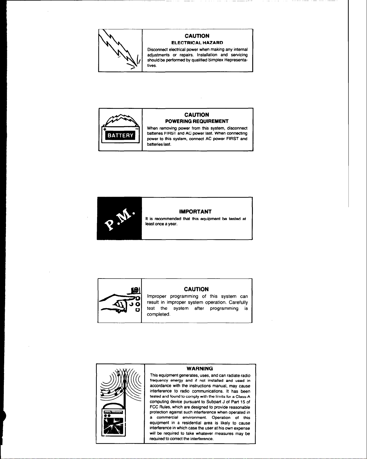
CAUTION
ELECTRICAL HAZARD
Disconnect electrical power when making any internal
adjustments or repairs. Installation and servicing
should be performed by qualified Simplex Representatives.
CAUTION
POWERING REQUIREMENT
When removing power from this system, disconnect
batteries FIRST and AC power last. When connecting
power to this system, connect AC power FIRST and
batteries last.
I
CAUTION
Improper programming of this system can
result in improper system operation. Carefully
test the system after programming is
completed.
I
This equipment generates, uses, and can radiate radio
frequency energy and if not installed and used in
accordance with the instructions manual, may cause
interference to radio communications. It has been
tested and found to comply with the limits for a Class A
computing device pursuant to Subpart J of Part 15 of
FCC Rules, which are designed to provide reasonable
protection against such interference when operated in
a commercial environment.
idential area is likely to cause
Operation of this
e user at his own expense
tever measures may be
I
Page 4

www.BevanSecurity.Com
Page 5
SECTION I- SYSTEM OVERVIEW
..................................................................................................................................................................................................................................................
www.BevanSecurity.Com
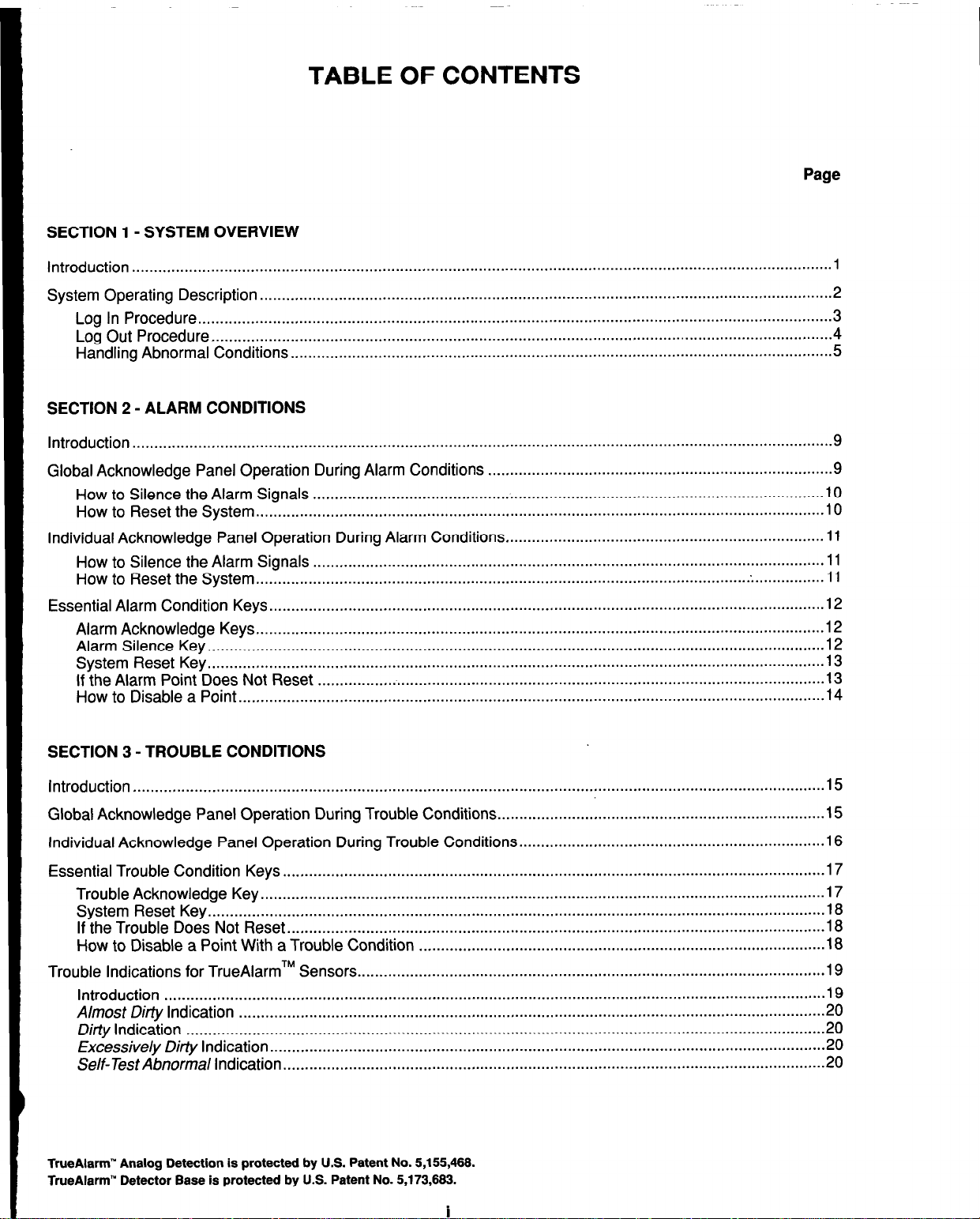
TABLE OF CONTENTS
Page
Introduction.. ..............................................................................................................................................................
System Operating Description..
Log In Procedure
Log Out Procedure..
Handling Abnormal Conditions
SECTION 2 - ALARM CONDITIONS
Introduction
Global Acknowledge Panel Operation During Alarm Conditions
How to Silence the Alarm Signals
How to Reset the System
Individual Acknowledge Panel Operation
How to Silence the Alarm Signals..
How to Reset the System
Essential Alarm Condition Keys
Alarm Acknowledge Keys..
Alarm Silence Key..
System Reset Key..
If the Alarm Point Does Not Reset
How to Disable a Point
................................................................................................................................................................ 9
.................................................................................................................................................
............................................................................................................................................
...........................................................................................................................................
...... .......
.................................................................................................................................
............................................................................................................................ 5
...............................................................................
.....................................................................................................................
..................................................................................................................................
During Alarm Conditions..
...................................................................................................................
..................................................................................................................................
...............................................................................................................................
................................................................................................................................
......................................................................................................................................
.......................................................................
1
2
3
4
9
10
10
11
11
11
12
12
12
;z
14
SECTION 3 - TROUBLE CONDITIONS
Introduction
Global Acknowledge Panel Operation
Individual Acknowledge Panel Operation During Trouble Conditions
Essential Trouble Condition Keys
Trouble Acknowledge Key
System Reset Key..
If the Trouble Does Not Reset
How to Disable a Point With a Trouble Condition
Trouble Indications for TrueAlarmTM Sensors
Introduction
Almost Dirty Indication
Ditiy Indication
Excessive/y Dirty Indication..
Self-Test Abnormal Indication
TrueAlarm” Analog Detection is protected by U.S. Patent No. $155,466.
TrueAlarm” Detector Base is protected by U.S. Patent No. 5,173,663.
............................................................................................................................................................. .15
During Trouble Conditions..
............................................................................................................................
.................................................................................................................................
...........................................................................................................................................
.......................................................................................................................... .18
.............................................................................................
...........................................................................................................
.......................................................................................................................................................
......................................................................................................................................
..................................................................................................................................................
.............................................................................................................................
............................................................................................................................
i
........................................................................
......................................................................
.15
16
17
17
18
18
19
19
20
20
20
20
Page 6
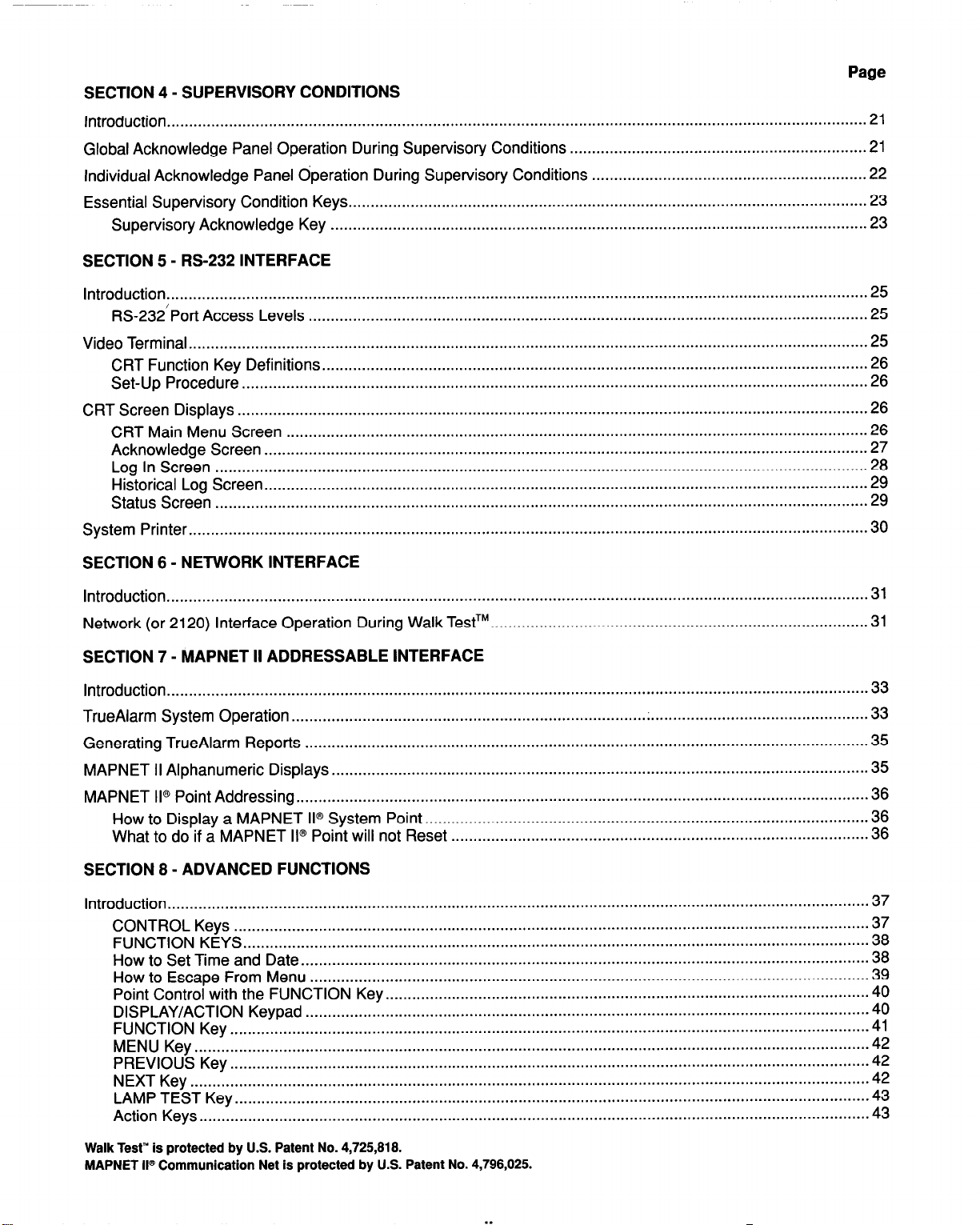
SECTION 4 - SUPERVISORY CONDITIONS
www.BevanSecurity.Com
Introduction
Global Acknowledge Panel Operation During Supervisory Conditions
Individual Acknowledge Panel
Essential Supervisory Condition Keys
Supervisory Acknowledge Key
SECTION 5 - RS-232 INTERFACE
..............................................................................................................................................................
dperation During Supervisory Conditions
.....................................................................................................................
.........................................................................................................................
Page
...................................................................
.............................................................
21
21
.22
23
23
Introduction
RS-232’Port Access Levels
Video Terminal.
CRT Function Key Definitions
Set-Up Procedure..
CRT Screen Displays
CRT Main Menu Screen
Acknowledge Screen
Log In Screen
Historical Log Screen
Status Screen
System Printer
SECTION 6 - NETWORK INTERFACE
Introduction
Network (or 2120) Interface Operation During Walk TestTM.
SECTION 7 - MAPNET II ADDRESSABLE INTERFACE
Introduction..
TrueAlarm System
Generating TrueAlarm Reports..
MAPNET II Alphanumeric Displays
MAPNET
How to Display a MAPNET II@ System Point
What to do if a MAPNET II@ Point will not Reset
..............................................................................................................................................................
..............................................................................................................................
........................................................................................................................................................
...........................................................................................................................
...........................................................................................................................................
.............................................................................................................................................. 26
................................................................................................................................... 26
........................................................................................................................................
...................................................................................................................................................
........................................................................................................................................
...................................................................................................................................................
.........................................................................................................................................................
..............................................................................................................................................................
....................................................................................
............................................................................................................................................................
Operation
II@ Point Addressing..
...............................................................................
.............................................................................................................................
.........................................................................................................................
...............................................................................................................................
....................................................................................................
..............................................................................................
.................................................
.;
25
25
25
26
26
27
28
29
29
30
31
31
33
33
35
35
36
36
36
SECTION 8 - ADVANCED FUNCTIONS
Introduction..
CONTROL Keys
FUNCTION KEYS
How to Set Time
How to Escape From Menu
Point Control with the
DISPLAY/ACTION Keypad
FUNCTION Key
MENU Key
PREVIOUS Key
NEXT Key
LAMP TEST Key..
Action Keys
Walk Test’” is protected by U.S. Patent No. 4,725,818.
MAPNET II@ Communication Net is protected by U.S. Patent No. 4,798,025.
............................................................................................................................................................
...............................................................................................................................................
.............................................................................................................................................
and Date..
FUNCTION Key..
................................................................................................................................................
........................................................................................................................................................
................................................................................................................................................
.........................................................................................................................................................
.............................................................................................................................................
...................................................................................................................................................... .43
..............................................................................................................................
..............................................................................................................................
...........................................................................................................
...............................................................................................................................
37
37
38
38
39
40
40
41
42
42
42
43
Page 7
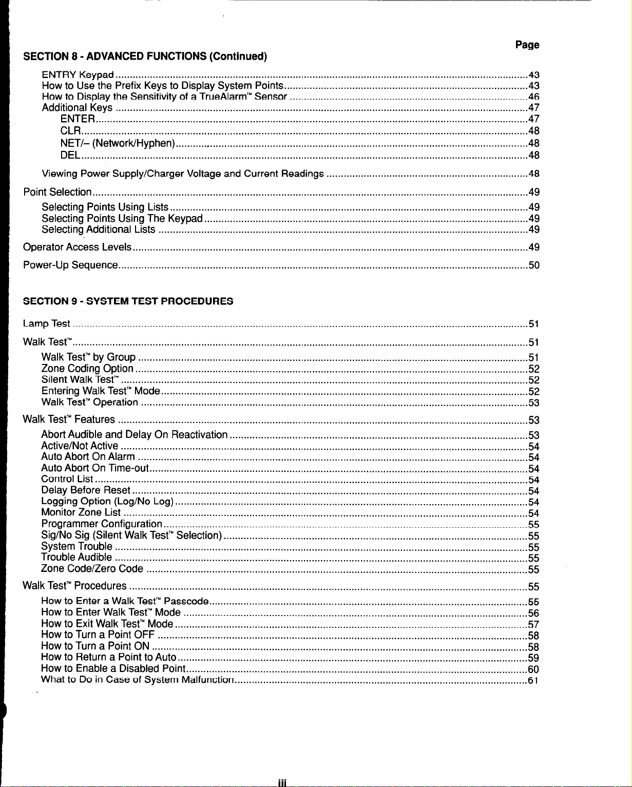
SECTION 8 - ADVANCED FUNCTIONS (Continued)
www.BevanSecurity.Com
ENTRY
How to
How to
Additional
Viewing
Point Selection..
Selecting
Selecting
Selecting
Operator Access
Power-Up
SECTION 9 -.SYSTEM TEST PROCEDURES
Keypad
Use the Prefix
Display the Sensitivity of a TrueAlarm” Sensor
ENTER..
.............................................................................................................................................................
CLR
NET/- (Network/Hyphen).
DEL.. ...........................................................................................................................................................
Power Supply/Charger Voltage and
Sequence.. ..............................................................................................................................................
.................................................................................................................................................
Keys to Display System
.................................................................................................................................................
Keys
......................................................................................................................................................
...........................................................................................................................
.......................................................................................................................................................
Points Using
Points Using
Additional Lists
Levels..
Lists.. ............................................................................................................................
The Keypad.. ...............................................................................................................
..................................................................................................................................
........................................................................................................................................
Points.. ...................................................................................
Current Readings
Page
...................................................................................
......................................................................
43
.43
.46
47
47
48
48
48
.48
49
49
.49
49
.49
50
Lamp Test
Walk Test’“.
Walk Test’” by Group
Zone Coding Option
Silent Walk Test’”
Entering Walk Test’” Mode
Walk Test’” Operation
Walk Test’” Features
Abort Audible and Delay On Reactivation
Active/Not Active
Auto Abort
Auto Abort On Time-out
Control List ........................................................................................................................................................
Delay Before Reset ...........................................................................................................................................
Logging Option (Log/No Log) ............................................................................................................................
Monitor Zone List
Programmer Configuration ................................................................................................................................
Sig/No
System Trouble..
Trouble Audible
Zone Code/Zero Code ......................................................................................................................................
Walk Test’” Procedures ............................................................................................................................................
How to Enter a Walk Test’” Passcode
How to Enter Walk Test’” Mode
How to Exit Walk Test’” Mode ............................................................................................................................
How to
How to Turn a Point ON ....................................................................................................................................
How to Return a Point to Auto ...........................................................................................................................
How to Enable a Disabled Point
What to Do in Case of System Malfunction
................................................................................................................................................................
...............................................................................................................................................................
.........................................................................................................................................
..........................................................................................................................................
...............................................................................................................................................
.................................................................................................................................
........................................................................................................................................
................................................................................................................................................
........................................................................................................
...............................................................................................................................................
On Alarm
Sig (Silent Walk Test’” Selection)
Turn a Point OFF ..................................................................................................................................
.........................................................................................................................................
.....................................................................................................................................
..............................................................................................................................................
...........................................................................................................
...............................................................................................................................................
.................................................................................................................................................
...............................................................................................................
........................................................................................................................
.......................................................................................................................
......................................................................................................
51
51
51
52
52
52
53
53
.53
54
54
54
54
54
54
54
55
55
55
55
55
55
.55
.56
57
58
58
59
.60
.61
. . .
Page 8
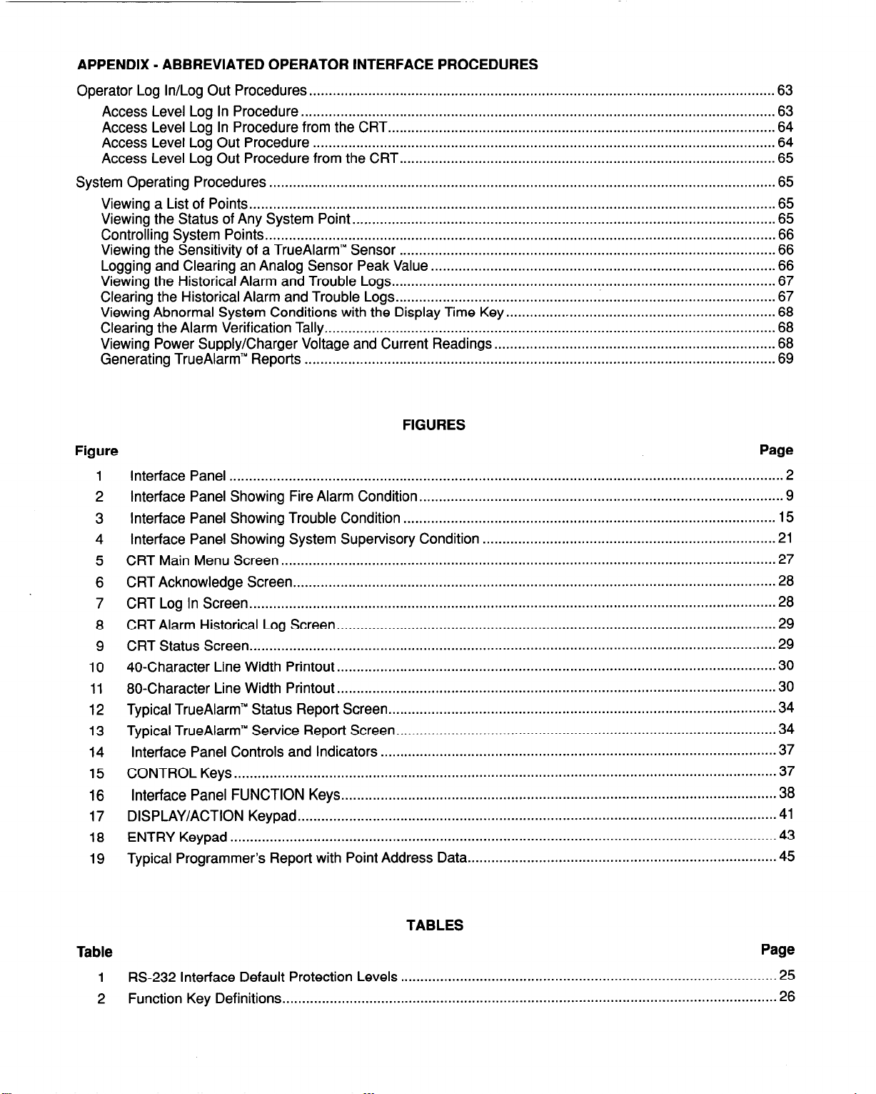
APPENDIX - ABBREVIATED OPERATOR INTERFACE PROCEDURES
www.BevanSecurity.Com
Operator Log In/Log
Access Level
Access Level
Access Level
Access Level
System Operating
Viewing a List
Viewing the Status of Any System Point
Controlling System
Viewing the Sensitivity
Logging and Clearing
Viewing the Historical Alarm
Clearing the Historical
Viewing Abnormal
Clearing the Alarm Verification Tally.
Viewing Power Supply/Charger Voltage and
Generating TrueAlarm”
Figure
1
Interface Panel
2
Interface Panel Showing Fire Alarm Condition
Interface
3
4
Interface Panel Showing System Supervisory Condition
CRT Main Menu Screen
5
CRT Acknowledge
6
7
CRT Log In Screen
CRT Alarm
8
9
CRT Status Screen
40-Character
10
80-Character Line Width Printout
11
12
Typical TrueAlarm” Status Report Screen
Typical TrueAlarm”
13
Interface Panel Controls and Indicators
14
CONTROL
15
Interface
16
17
DISPLAY/ACTION Keypad
ENTRY Keypad .........................................................................................................................................
18
Typical Programmer’s Report with Point Address Data
19
Out Procedures.. ...................................................................................................................
Log In Procedure..
Log In Procedure from the CRT.. ...............................................................................................
Log Out Procedure ....................................................................................................................
Log Out Procedure from the CRT.. ............................................................................................
Procedures
of Points.. ...................................................................................................................................
Points.. ...............................................................................................................................
of a TrueAlarm” Sensor ..............................................................................................
an Analog Sensor Peak Value.. ....................................................................................
Alarm and Trouble Logs.. ..............................................................................................
System Conditions with the Display Time Key.. .................................................................
Reports ......................................................................................................................
............................................................................................................................................
Panel Showing Trouble Condition
Screen..
....................................................................................................................................
Historical Log Screen..
.....................................................................................................................................
Line Width Printout..
Service Report
.......................................................................................................................................
Keys..
Panel FUNCTION Keys.. ...........................................................................................................
...................................................................................................................... 63
................................................................................................................................ 65
and Trouble Logs.. ..............................................................................................
.............................................................................................................................
........................................................................................................................
.........................................................................................................................
.63
.64
.64
.65
65
........................................................................................................... 65
66
.66
.66
.67
.67
.68
................................................................................................................. 68
Current Readings.. ....................................................................
FIGURES
............................................................................................
..............................................................................................
..........................................................................
.............................................................................................................
............................................................................................................
..............................................................................................................
.................................................................................................
Screen..
.............................................................................................
....................................................................................................
..............................................................................
.68
.69
Page
2
9
15
21
27
28
.28
29
29
.30
.30
.34
.34
37
37
.38
41
.43
45
Table
1
RS-232 Interface
2
Function Key Definitions
Default Protection
TABLES
Page
Levels . . . . . . . . . . . . . . . . . . . . . . . . . . . . . . . . . . . . . . . . . . . . . . . . . . . . . . . . . . . . . . . . . . . . . . . . . . . . . . . . . . . . . . . . . . . . . . . 25
. . . . . . . . . . . . . . . . . . . . . . . . . . . . . . . . . . . . . . . . . . . . . . . . . . . . . . . . . . . . . . . . . . . . . . . . . . . . . . . . . . . . . . . . . . . . . . . . . . . . . . . . . . . . . . . . . . . . . . . . .....
26
Page 9

INTRODUCTION
www.BevanSecurity.Com
SECTION 1
SYSTEM OVERVIEW
The Simplex 4020 is a microprocessor-based Fire Alarm System.
It is UL-listed, power-limited, electrically-
supervised, and protected against loss of primary AC power and brown-out conditions.
The standard 4020 can control up to 127 MAPNET II@ points. Depending on options, the 4020 can control a
maximum of 254 addressable points. Since all points in a system may not be addressable, the 4020 also offers up
to 20 hardwired points (with 4 points standard) that can be used to interface with detector zones, bell or horn circuits,
and auxiliary relay control. Each hardwired point is individually configurable as either a monitor point, a signal circuit,
or as an auxiliary relay output, with up to 8 different points on a single card.
The 4020 offers a variety of ways to provide remote annunciation. It can communicate with the LCD annunciator,
the SCWRCU, or the graphic SCWRCU. The RS-232 interface can be used to output to a printer or CRT.
An alphanumeric display on the 4020 Operator Interface Panel (Figure 1) indicates the condition of the system. The
alphanumeric display shows various prompts and labels which guide the user through a sequenced operation for
each abnormal condition. Audible and visual indications are provided to indicate abnormal conditions when they
exist within the system.
The 4020 capacities are as follows:
l
Up to two MAPNET II@ channels with up to 127 addressable devices each for a total of 254 addressable
devices
l
Up to 20 hardwired points, configurable as monitor, signal, or auxiliary relay points
l
An RS-232 interface
l
Up to 31 remote annunciator locations, which can accommodate SCWRCU, graphic SCU/RCU, and LCD
annunciators
l
An 8-Amp switching power supply, with a battery charger capable of charging batteries with up to 50 Ah
capacity.
The default hardware for a 4020 includes a master controller with a display, master trouble points, city circuit, and
tone-alert. The standard slave module uses three card addresses. “Card (address) 1 W functions like an 8-point multifunction I/O card, but only the first 4 points are available. “Card 2” is the power supply card. “Card 3” is the built-in
MAPNET@ channel.
The following optional hardware is allowed:
l
An additional MAPNET II@ card
l
Two eight-point multifunctional I/O cards
l
An RS-232 interface card configured with two isolated ports, with the ability for one port to be dedicated to
communications with a 2120 Multiplex System.
l
Serial annunciators including the LCD display, the SCWRCU, or the graphic SCWRCU
l
4120 Network Interface
l
25.5 Volt Limiter Module for Agent Release.
NOTE: This document covers operating procedures for a typical 4020 system. Applications will vary due to optional
hardware installed, custom programming, and local code requirements.
Page 10
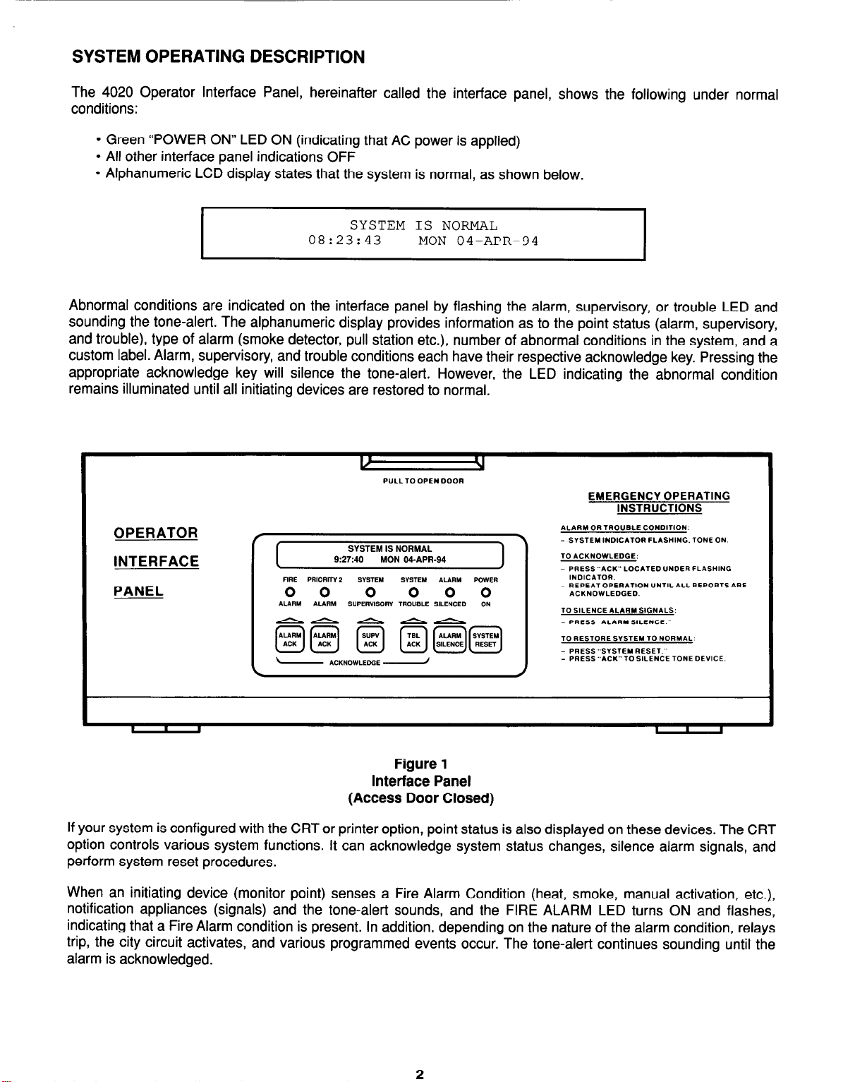
SYSTEM OPERATING DESCRIPTION
www.BevanSecurity.Com
The 4020 Operator Interface Panel, hereinafter called the interface panel, shows the following under normal
conditions:
l
Green “POWER ON” LED ON (indicating that AC power is applied)
l
All other interface panel indications OFF
l
Alphanumeric LCD display states that the system is normal, as shown below.
SYSTEM IS NORMAL
08:23:43
I
Abnormal conditions are indicated on the interface panel by flashing the alarm, supervisory, or trouble LED and
sounding the tone-alert. The alphanumeric display provides information as to the point status (alarm, supervisory,
and trouble), type of alarm (smoke detector, pull station etc.), number of abnormal conditions in the system, and a
custom label. Alarm, supervisory, and trouble conditions each have their respective acknowledge key. Pressing the
appropriate acknowledge key will silence the tone-alert. However, the LED indicating the abnormal condition
remains illuminated until all initiating devices are restored to normal.
MON 04-APR-94
I
If your system is configured with the CRT or printer option, point status is also displayed on these devices. The CRT
option controls various system functions. It can acknowledge system status changes, silence alarm signals, and
perform system reset procedures.
When an initiating device (monitor point) senses a Fire Alarm Condition (heat, smoke, manual activation, etc.),
notification appliances (signals) and the tone-alert sounds, and the FIRE ALARM LED turns ON and flashes,
indicating that a Fire Alarm condition is present. In addition, depending on the nature of the alarm condition, relays
trip, the city circuit activates, and various programmed events occur. The tone-alert continues sounding until the
alarm is acknowledged.
Figure 1
Interface Panel
(Access Door Closed)
2
Page 11

When an initiating device senses a System Supervisory Condition (tamper valve off normal, generator status, etc.),
www.BevanSecurity.Com
programmed notification appliances and the tone-alert sounds, the SYSTEM SUPERVISORY LED on the interface
panel turns ON and flashes, the city circuit may be activated (if required by local codes), and various programmed
events occur. The tone-alert continues sounding until the condition is acknowledged or cleared.
When the 4020 senses a malfunction within the system (loss of power, hardware failure, etc.), a Trouble Condition
is announced by the interface panel. The tone-alert sounds steady, the SYSTEM TROUBLE LED flashes and
various programmed events occur. The tone-alert continues sounding until the condition is acknowledged or
cleared.
NOTE: When an operator interface panel key is referenced within this manual, it is normally shown between left
and right arrows. Examples are cACK> and <ALARM SILENCE>.
All abnormal conditions must be acknowledged by pressing the cACK> key under the appropriate flashing LED.
Notification appliances are silenced by pressing the <ALARM SILENCE> key.
NOTE: When you press the <ALARM SILENCE> key, the ALARM SILENCED LED turns ON steady.
Depressing the <SYSTEM RESET> key restores the system to the normal operating mode if Fire Alarm Conditions
have been acknowledged and restored. Depressing the <PRIORITY 2 ALARM RESET> key on the CONTROL Key
Panel restores the system to normal operation if Priority 2 Alarm Conditions have been acknowledged and restored.
(All keys on the CONTROL Key Panel must be programmed for function.)
The tone-alert may be programmed to sound at specified time intervals to serve as a reminder that a trouble still
exists within the system (System Trouble Reminder).
The system has “re-sound” capability. If, after silencing the signals, the system detects another abnormal condition,
the zone with the abnormal condition is indicated on the interface panel alphanumeric display, the appropriate
indicator again flashes, and the signals again sound.
To provide maximum efficiency in performing primary fire alarm functions, an interface panel access door, shown in
Figure 1, covers all keys except those required for indication and interaction for emergency situations. (The access
door must be opened to reset Priority 2 Alarm Conditions.)
LOG IN PROCEDURE
NOTE: Various functions may be passcode protected to prevent access by unauthorized personnel. Passcodes
are provided to the user during system installation. To change or receive additional information concerning
your passcodes, contact your local Simplex Branch Office.
To Log In, perform the following procedure.
1. Obtain the appropriate passcode information.
2. Open the interface panel access door.
3. Press the <MENU> key on the Display/Action keypad on the right side of the interface panel. The
alphanumeric display shows the following message.
Press <NEXT> or <PREVIOUS> to scroll
Change Access Level?
I
4. Press the <ENTER> key on the Display/Action keypad. The following message is displayed.
Fl=Login F2=Logout
CURRENT ACCESS LEVEL = 1
I
Page 12
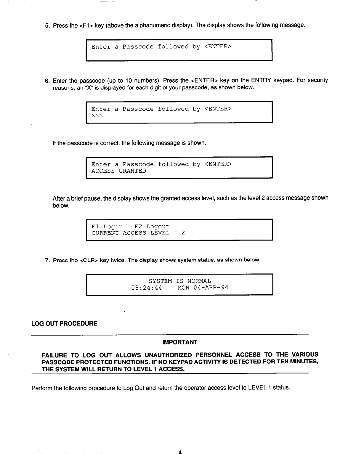
5. Press the <Fl> key (above the alphanumeric display). The display shows the following message.
www.BevanSecurity.Com
Enter a Passcode followed by <ENTER>
I
6. Enter the passcode (up to 10 numbers). Press the <ENTER> key on the ENTRY keypad. For security
reasons, an “X” is displayed for each digit of your passcode, as shown below.
Enter a Passcode followed by <ENTER>
xxx
I
If the passcode is correct, the following message is shown.
Enter a Passcode followed by <ENTER>
ACCESS GRANTED
I
After a brief pause, the display shows the granted access level, such as the level 2 access message shown
below.
Fl=Login F2=Logout
CURRENT ACCESS LEVEL = 2
I
7. Press the <CLR> key twice. The display shows system status, as shown below.
SYSTEM IS NORMAL
08:24:44 MON 04-APR-94
LOG OUT PROCEDURE
IMPORTANT
FAILURE TO LOG OUT ALLOWS UNAUTHORIZED PERSONNEL ACCESS TO THE VARIOUS
PASSCODE PROTECTED FUNCTIONS. IF NO KEYPAD ACTIVITY IS DETECTED FOR TEN MINUTES,
THE SYSTEM WILL RETURN TO LEVEL 1 ACCESS.
I
Perform the following procedure to Log Out and return the operator access level to LEVEL 1 status.
Page 13
1. Press the <MENU> key. The following message is displayed.
www.BevanSecurity.Com
Press <NEXT> or <PREVIOUS> to scroll
Change Access Level?
2. Press the <ENTER> key. The following message is displayed.
Fl=Login F2=Logout
CURRENT ACCESS LEVEL = 2
I
3. Press the cF2> key. After a brief pause, the display shows a message similar to the one below.
Fl=Login F2=Logout
ACCESS LEVEL REDUCED TO LEVEL 1
I
4. Press the cCLR> key to exit. The display will show a message similar to one of the following messages.
I
I
SYSTEM IS NORMAL
9:27:40 MON 04-APR-94
**TROUBLE** Press <ACK>
FIRE = 0 PR12 = 0 SUPV = 0
I
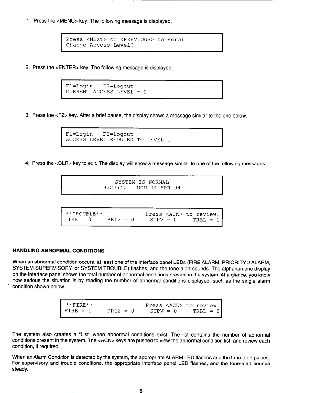
HANDLING ABNORMAL CONDITIONS
When an abnormal condition occurs, at least one of the interface panel LEDs (FIRE ALARM, PRIORITY 2 ALARM,
SYSTEM SUPERVISORY, or SYSTEM TROUBLE) flashes, and the tone-alert sounds. The alphanumeric display
on the interface panel shows the total number of abnormal conditions present in the system. At a glance, you know
how serious the situation is by reading the number of abnormal conditions displayed, such as the single alarm
- condition shown below.
**FIRE**
FIRE = 1 PR12 = 0 SUPV = 0
I
Press <ACK> to review.
TRBL = 0
I
The system also creates a “List” when abnormal conditions exist. The list contains the number of abnormal
conditions present in the system. The cACK> keys are pushed to view the abnormal condition list, and review each
condition, if required.
When an Alarm Condition is detected by the system, the appropriate ALARM LED flashes and the tone-alert pulses.
For supervisory and trouble conditions, the appropriate interface panel LED flashes, and the tone-alert sounds
steady.
Page 14
Pressing the appropriate cACK> key (under the flashing LED) displays the first acknowledged condition in the
www.BevanSecurity.Com
appropriate list. Note that the cACK> function may be passcode protected. If you have insufficient privilege to
acknowledge the condition, a message will indicate the problem, and will allow you to view the points without
acknowledging them. If you have sufficient privilege to acknowledge the condition, a message is displayed informing
you that the condition has been acknowledged. (See Operator Access Levels, Section 8, and Log In Procedure,
Section 1, for details.)
The 4020 system can be configured with either Global or Individual Acknowledge. When Global Acknowledge is
used in the system, one press of an <ACK> key globally acknowledges every abnormal point in the system in that
category. If all the points are acknowledged in this manner, an appropriate message is displayed. When Global
Acknowledge is used in a system, and the supervisory service or trouble conditions clears, the abnormal condition
automatically clears. Alarm conditions must be acknowledged. If Individual Acknowledge is used in the system, the
appropriate <ACK> key must be pressed for each condition change.
Note that the acknowledge function imposes a delay of at least one second between point acknowledgments. This
minimum delay allows you to view the information displayed on the alphanumeric display for each point that is being
acknowledged by the cACK> key.
When a point is acknowledged, the interface panel status LED glows steady, and the tone-alert silences. The total
number of alarm, supervisory, and trouble conditions show on the alphanumeric display along with a prompt to press
the cACK> key for point review. Pressing the cACK> key scrolls through the selected list in chronological order.
Each list is different and contains information concerning a particular abnormal condition.
After 30 seconds of keypad inactivity, the total number of abnormal conditions is again shown on the alphanumeric
display. Pressing the cACK> key selects a list for review. The first point to be displayed is either the first
acknowledged point in the list, or the first point in the list if all are acknowledged.
Alarm, supervisory, and trouble lists are displayed in chronological order. A message will indicate when the end of
a list has been reached.
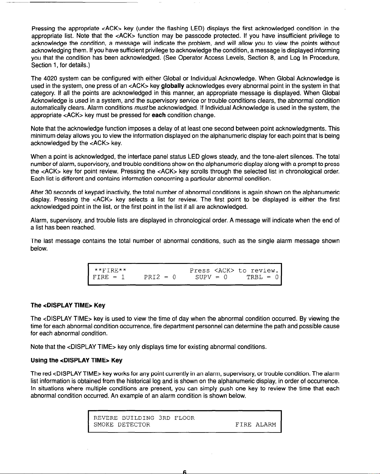
The last message contains the total number of abnormal conditions, such as the single alarm message shown
below.
**FIRE**
FIRE = 1 PRIZ = 0 SUPV = 0 TRBL = 0
I
The <DISPLAY TIME> Key
The <DISPLAY TIME> key is used to view the time of day when the abnormal condition occurred. By viewing the
time for each abnormal condition occurrence, fire department personnel can determine the path and possible cause
for each abnormal condition.
Note that the <DISPLAY TIME> key only displays time for existing abnormal conditions.
Using the <DISPLAY TIME* Key
The red <DISPLAY TIME> key works for any point currently in an alarm, supervisory, or trouble condition. The alarm
list information is obtained from the historical log and is shown on the alphanumeric display, in order of occurrence.
In situations where multiple conditions are present, you can simply push one key to review the time that each
abnormal condition occurred. An example of an alarm condition is shown below.
Press <ACK> to review.
REVERE BUILDING 3RD FLOOR
SMOKE DETECTOR FIRE ALARM
I
I
Page 15
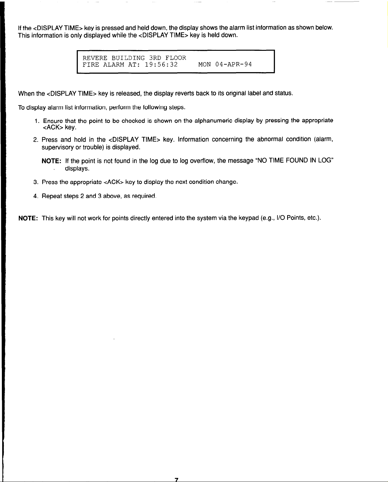
If the <DISPLAY TIME> key is pressed and held down, the display shows the alarm list information as shown below.
www.BevanSecurity.Com
This information is only displayed while the <DISPLAY TIME> key is held down.
REVERE BUILDING 3RD FLOOR
FIRE ALARM AT: 19:56:32
I
When the <DISPLAY TIME> key is released, the display reverts back to its original label and status.
To display alarm list information, perform the following steps.
1. Ensure that the point to be checked is shown on the alphanumeric display by pressing the appropriate
cACK> key.
2. Press and hold in the <DISPLAY TIME> key. Information concerning the abnormal condition (alarm,
supervisory or trouble) is displayed.
NOTE: If the point is not found in the log due to log overflow, the message “NO TIME FOUND IN LOG”
, displays.
3. Press the appropriate cACK> key to display the next condition change.
4. Repeat steps 2 and 3 above, as required.
MON 04-APR-94
I
NOTE: This key will not work for points directly entered into the system via the keypad (e.g., I/O Points, etc.).
Page 16

www.BevanSecurity.Com
Page 17
SECTION 2
www.BevanSecurity.Com
ALARM CONDITIONS
INTRODUCTION
CAUTION
FOLLOW LOCAL OPERATING PROCEDURES WHEN INVESTIGATING ALARM CONDITIONS.
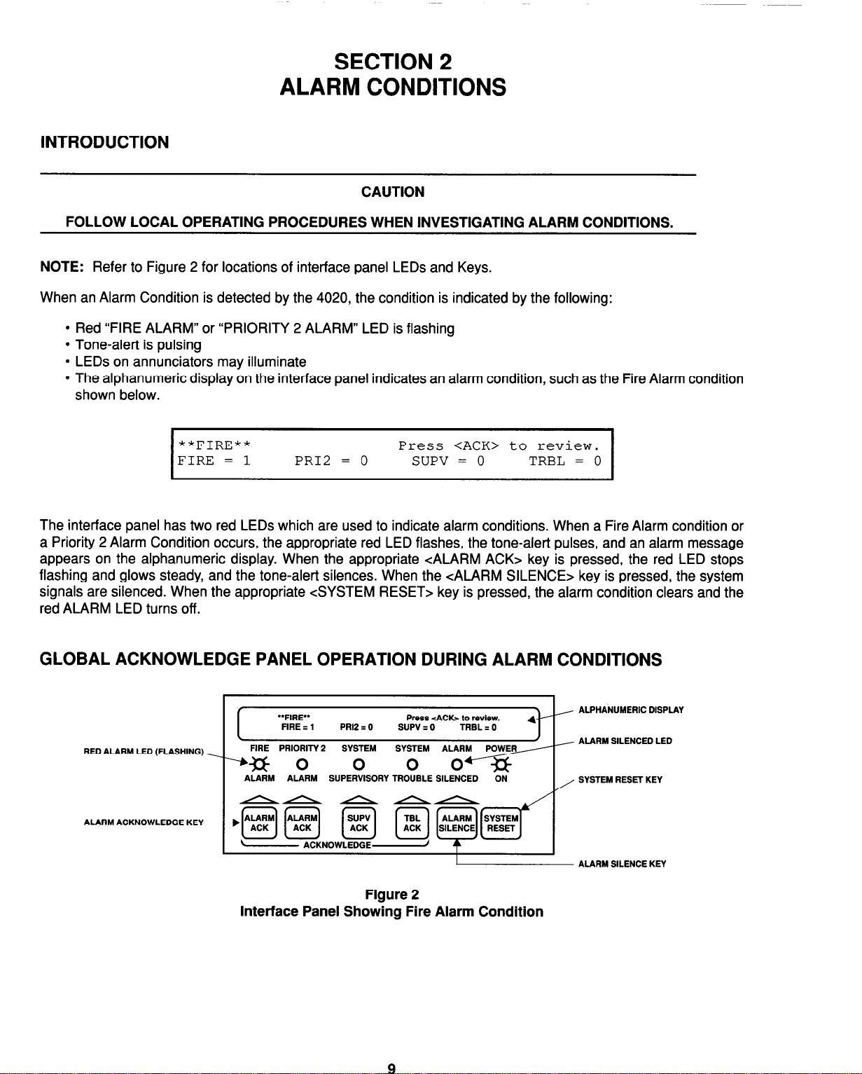
NOTE: Refer to Figure 2 for locations of interface panel LEDs and Keys.
When an Alarm Condition is detected by the 4020, the condition is indicated by the following:
l
Red “FIRE ALARM” or “PRIORITY 2 ALARM” LED is flashing
l
Tone-alert is pulsing
l
LEDs on annunciators may illuminate
l
The alphanumeric display on the interface panel indicates an alarm condition, such as the Fire Alarm condition
shown below.
**FIRE**
FIRE = 1 PR12 = 0
I
Press <ACK> to review.
SUPV = 0
TRBL = 0
I
The interface panel has two red LEDs which are used to indicate alarm conditions. When a Fire Alarm condition or
a Priority 2 Alarm Condition occurs, the appropriate red LED flashes, the tone-alert pulses, and an alarm message
appears on the alphanumeric display. When the appropriate <ALARM ACK> key is pressed, the red LED stops
flashing and glows steady, and the tone-alert silences. When the <ALARM SILENCE> key is pressed, the system
signals are silenced. When the appropriate <SYSTEM RESET> key is pressed, the alarm condition clears and the
red ALARM LED turns off.
GLOBAL ACKNOWLEDGE PANEL OPERATION DURING ALARM CONDITIONS
/ ALPHANUMERIC DISPLAY
J
/ ALARM SILENCED LED
, SYSTEM RESET KEY
RED ALARM LED (FLASHING)
ALARM ACKNOWLEDGE KEY
‘*FIRE** Press <ACb to review.
I
I
--% 0
FIRE z 1 PRl2 I 0 SUPV : 0
FlRE PRIORITY 2
ALARM ALARM SUPERVISORY TROUBLE SILENCED
TRBL I 0
-ON-
Interface Panel Showing Fire Alarm Condition
I ALARM SILENCE KEY
Figure 2
Page 18
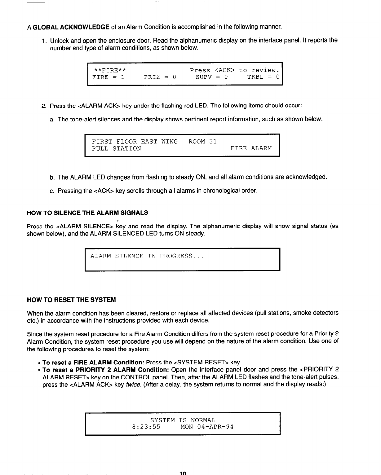
A GLOBAL ACKNOWLEDGE of an Alarm Condition is accomplished in the following manner.
www.BevanSecurity.Com
1. Unlock and open the enclosure door. Read the alphanumeric display on the interface panel. It reports the
number and type of alarm conditions, as shown below.
**FIRE**
FIRE = 1
I
2. Press the <ALARM ACK> key under the flashing red LED. The following items should occur:
a. The tone-alert silences and the display shows pertinent report information, such as shown below.
FIRST FLOOR EAST WING ROOM 31
PULL STATION FIRE ALARM
I
b. The ALARM LED changes from flashing to steady ON, and all alarm conditions are acknowledged.
c. Pressing the cACK> key scrolls through all alarms in chronological order.
HOW TO SILENCE THE ALARM SIGNALS
+
Press the <ALARM SILENCE> key and read the display. The alphanumeric display will show signal status (as
shown below), and the ALARM SILENCED LED turns ON steady.
PR12 = 0
Press <ACK> to review.
SUPV = 0 TRBL = 0
I
I
ALARM SILENCE IN PROGRESS...
I
HOW TO RESET THE SYSTEM
When the alarm condition has been cleared, restore or replace all affected devices (pull stations, smoke detectors
etc.) in accordance with the instructions provided with each device.
Since the system reset procedure for a Fire Alarm Condition differs from the system reset procedure for a Priority 2
Alarm Condition, the system reset procedure you use will depend on the nature of the alarm condition. Use one of
the following procedures to reset the system:
l
To reset a FIRE ALARM Condition: Press the <SYSTEM RESET> key.
l
To reset a PRIORITY 2 ALARM Condition: Open the interface panel door and press the <PRIORITY 2
ALARM RESET> key on the CONTROL panel. Then, after the ALARM LED flashes and the tone-alert pulses,
press the <ALARM ACK> key twice. (After a delay, the system returns to normal and the display reads:)
SYSTEM IS NORMAL
8:23:55 MON 04-APR-94
I
Page 19
INDIVIDUAL ACKNOWLEDGE PANEL OPERATION DURING ALARM CONDITIONS
www.BevanSecurity.Com
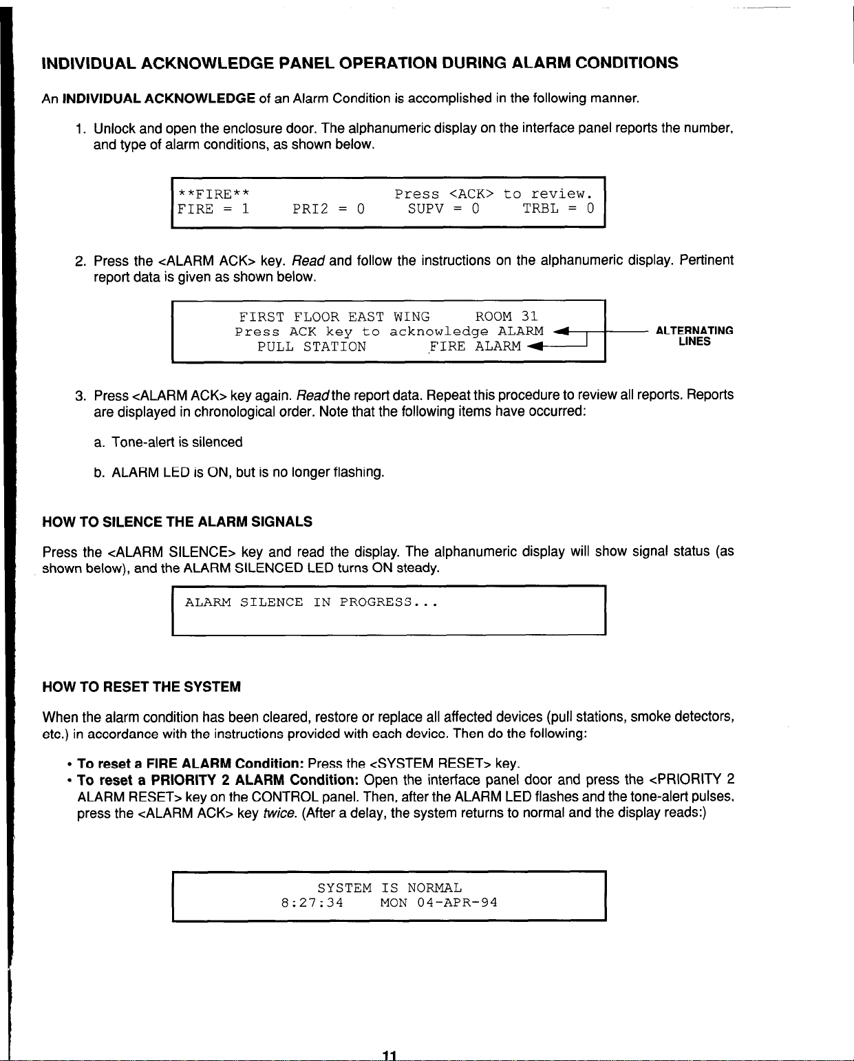
An INDIVIDUAL ACKNOWLEDGE of an Alarm Condition is accomplished in the following manner.
1. Unlock and open the enclosure door. The alphanumeric display on the interface panel reports the number,
and type of alarm conditions, as shown below.
**FIRE**
FIRE = 1 PR12 = 0 SUPV = 0
2. Press the <ALARM ACK> key. Read and follow the instructions on the alphanumeric display. Pertinent
report data is given as shown below.
Press <ACK> to review.
TRBL = 0
FIRST FLOOR EAST WING
Press ACK key to acknowledge ALARM
PULL STATION
3. Press <ALARM ACK> key again. Readthe report data. Repeat this procedure to review all reports. Reports
are displayed in chronological order. Note that the following items have occurred:
a. Tone-alert is silenced
b. ALARM LED is ON, but is no longer flashing.
HOW TO SILENCE THE ALARM SIGNALS
Press the <ALARM SILENCE> key and read the display. The alphanumeric display will show signal status (as
shown below), and the ALARM SILENCED LED turns ON steady.
,FIRE ALARM
ALARM SILENCE IN PROGRESS...
I
HOW TO RESET THE SYSTEM
When the alarm condition has been cleared, restore or replace all affected devices (pull stations, smoke detectors,
etc.) in accordance with the instructions provided with each device. Then do the following:
l
To reset a FIRE ALARM Condition: Press the <SYSTEM RESET> key.
l
To reset a PRIORITY 2 ALARM Condition: Open the interface panel door and press the <PRIORITY 2
ALARM RESET> key on the CONTROL panel. Then, after the ALARM LED flashes and the tone-alert pulses,
press the <ALARM ACK> key twice. (After a delay, the system returns to normal and the display reads:)
I
SYSTEM IS NORMAL
8:27:34
MON 04-APR-94
Page 20
ESSENTIAL ALARM CONDITION KEYS
www.BevanSecurity.Com
The essential keys for alarm conditions are the <ALARM ACK> (Alarm Acknowledge), <ALARM SILENCE>, and the
<SYSTEM RESET> keys. The remaining keys are concealed by the interface panel access door and are associated
with advanced system functions. (See Section 8, Advanced Functions.)
ALARM ACKNOWLEDGE KEYS
The <ALARM ACK> keys are located directly under the FIRE ALARM LED and the PRIORITY 2 ALARM LED.
Pressing the <ALARM ACK> key (twice for Individual Acknowledge or once for Global Acknowledge) causes the
ALARM LED to change from flashing to steady ON and silences the tone-alert. Pressing the <ALARM ACK> key
does the following:
l
Selects the next unacknowledged alarm point in the list for display (Individual Acknowledge)
l
Acknowledges the displayed point or acknowledges all points on the list (Global Acknowledge)
l
Scrolls the points chronologically after all points have been acknowledged.
If the <ALARM ACK> key is passcode protected, you cannot use this key to acknowledge alarms unless you have
the required access level. (See Operator Access Levels, Section 8, and Log In Procedure, Section 1.)
There are two types of acknowledges for the 4020 system: Global Acknowledge and Individual Acknowledge. Each
acknowledge type operates with the System Alarm Condition in the following manner.
l
Global Acknowledge - When Global Acknowledge is used on the 4020 system, a single key press of the
<ALARM ACK> key acknowledges all alarm status changes in the system. If status change information is
required, you may review this data by pressing the <ALARM ACK> key and reading the alphanumeric display.
l
Individual Acknowledge (For NFPA 72 Proprietary Receiver Requirements) - If an alarm condition has
been acknowledged with the <ALARM ACK> key and further unacknowledged conditions remain in the
system, the tone-alert continues sounding and the next status change shows on the alphanumeric display.
This process repeats until all changes are acknowledged. When this occurs, the tone-alert silences, and the
highest priority acknowledge change appears on the display.
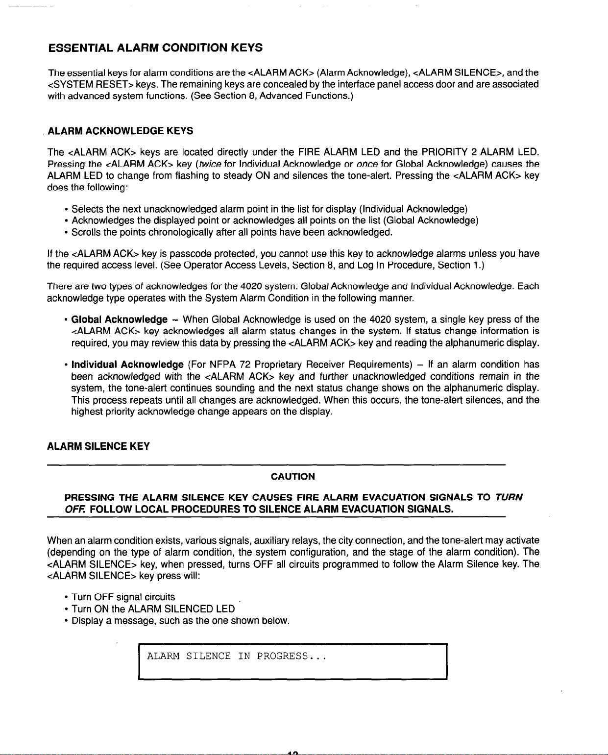
ALARM SILENCE KEY
CAUTION
PRESSING THE ALARM SILENCE KEY CAUSES FIRE ALARM EVACUATION SIGNALS TO TURN
OFF: FOLLOW LOCAL PROCEDURES TO SILENCE ALARM EVACUATION SIGNALS.
When an alarm condition exists, various signals, auxiliary relays, the city connection, and the tone-alert may activate
(depending on the type of alarm condition, the system configuration, and the stage of the alarm condition). The
<ALARM SILENCE> key, when pressed, turns OFF all circuits programmed to follow the Alarm Silence key. The
<ALARM SILENCE> key press will:
l
Turn OFF signal circuits
l
Turn ON the ALARM SILENCED LED
l
Display a message, such as the one shown below.
ALARM SILENCE IN PROGRESS...
Page 21
Alarm Silence Software Considerations
www.BevanSecurity.Com
The following software functions affect ALARM SILENCE operation.
l
If a Coded Input Device is activated, the <ALARM SILENCE> key press may be ignored until this function
has completed coding. Notification appliances cannot be silenced when a coded station is in alarm. However,
the flashing LED will change from flashing ON to steady ON when the <ALARM ACK> key is pushed. The
notification appliances silence automatically upon coding completion.
l
If the Alarm Silence Inhibit Function is activated but not completed, the <ALARM SILENCE> key press is
ignored. The message, “ALARM SILENCE INHIBITED”, displays for a short time to indicate the action was not
taken. The message “ALARM SILENCE NO LONGER INHIBITED” displays when the inhibit function times
out. If selected, the alarm silence inhibit may be programmed from 1 to 99 minutes. When selected, signals
cannot be silenced until the programmed time has elapsed.’
l
If Waterflow/Sprinkler Devices are activated, notification appliances may or may not be silenced (depending
on local code requirements). Usually, a dedicated bell will continue to sound to indicate water flow.
l
Some visual notification appliances may continue to flash until the system is reset.
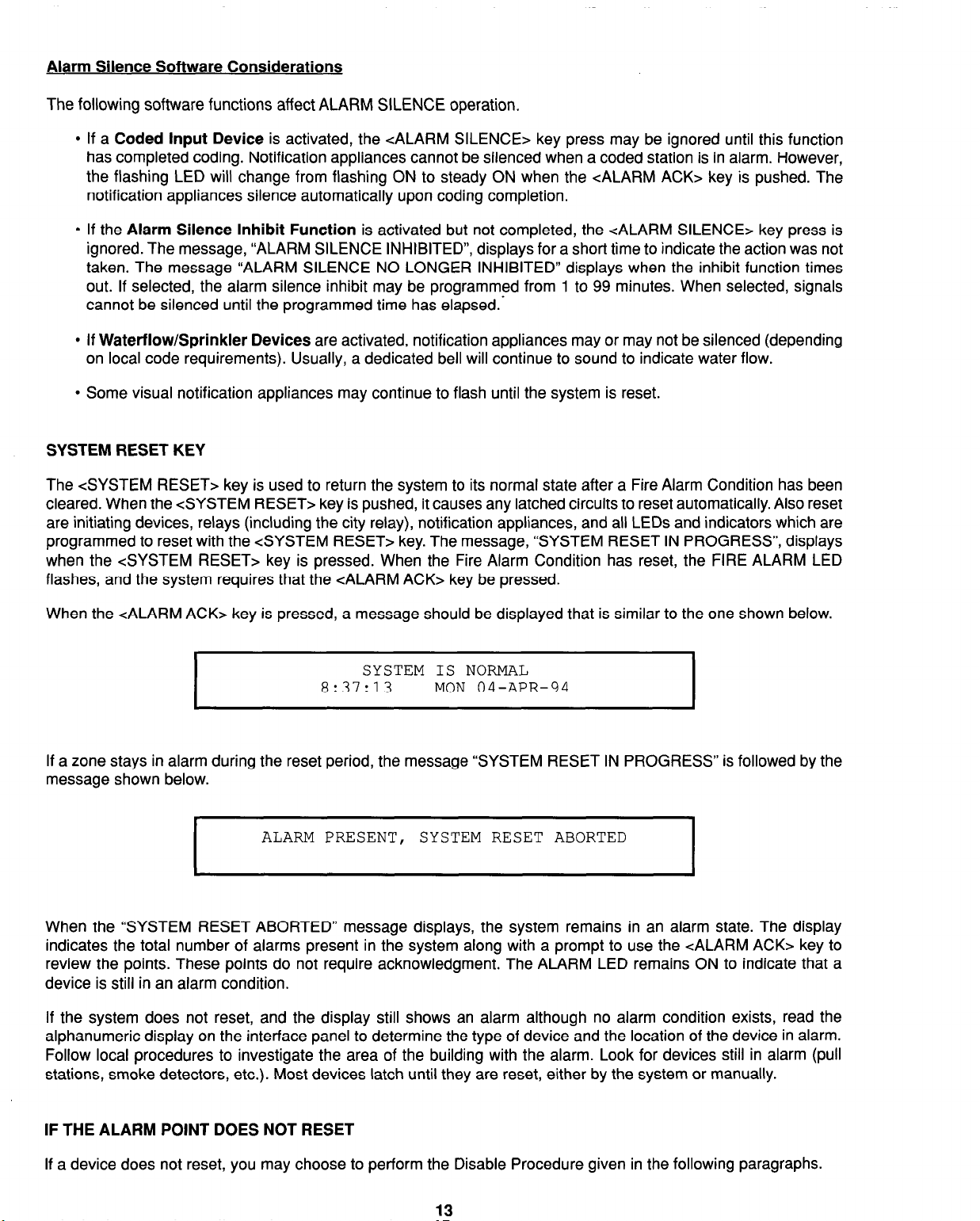
SYSTEM RESET KEY
The <SYSTEM RESET> key is used to return the system to its normal state after a Fire Alarm Condition has been
cleared. When the <SYSTEM RESET> key is pushed, it causes any latched circuits to reset automatically. Also reset
are initiating devices, relays (including the city relay), notification appliances, and all LEDs and indicators which are
programmed to reset with the <SYSTEM RESET> key. The message, “SYSTEM RESET IN PROGRESS”, displays
when the <SYSTEM RESET> key is pressed. When the Fire Alarm Condition has reset, the FIRE ALARM LED
flashes, and the system requires that the <ALARM ACK> key be pressed.
When the <ALARM ACK> key is pressed, a message should be displayed that is similar to the one shown below.
SYSTEM IS NORMAL
8:37:13 MON 04-APR-94
If a zone stays in alarm during the reset period, the message “SYSTEM RESET IN PROGRESS” is followed by the
message shown below.
ALARM PRESENT, SYSTEM RESET ABORTED
I
When the “SYSTEM RESET ABORTED” message displays, the system remains in an alarm state. The display
indicates the total number of alarms present in the system along with a prompt to use the <ALARM ACK> key to
review the points. These points do not require acknowledgment. The ALARM LED remains ON to indicate that a
device is still in an alarm condition.
If the system does not reset, and the display still shows an alarm although no alarm condition exists, read the
alphanumeric display on the interface panel to determine the type of device and the location of the device in alarm.
Follow local procedures to investigate the area of the building with the alarm. Look for devices still in alarm (pull
stations, smoke detectors, etc.). Most devices latch until they are reset, either by the system or manually.
IF THE ALARM POINT DOES NOT RESET
If a device does not reset, you may choose to perform the Disable Procedure given in the following paragraphs.
13
Page 22
HOW TO DISABLE A POINT
www.BevanSecurity.Com
CAUTION
DISABLING A POINT CAUSES THAT POINT TO NOT REPORT ALARM CONDITIONS OR OTHER
STATUS CHANGES. A POINT SHOULD NOT BE DISABLED UNLESS IT IS CLEARLY UNDERSTOOD
THAT FIRE DETECTION OR SECURITY FOR THE AREA OF THE BUILDING COVERED BY THAT
POINT WILL BE LOST. APPROPRIATE STEPS MUST BE TAKEN TO PROVIDE ALTERNATE MEANS
OF PROTECTION FOR THAT AREA OF THE BUILDING WHILE THE POINT IS DISABLED.
If a device does not reset, you may disconnect the device/point causing the alarm condition. However, this point
must first be identified. Press the <ALARM ACK> key, and read the alphanumeric display on the interface panel.
Then disable the identified alarm point with the <DISABLE> key. If the <DISABLE> key is passcode protected,
perform the Log In Procedure before performing the Disable Procedure.
The <DISABLE> key press removes power to any displayed monitor point. Thus, disabling a point causes a trouble
condition on the individual zone.
To disable a point, perform the following procedure.
1. Open the interface panel access door.
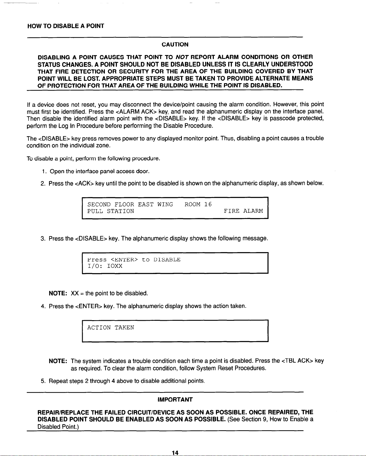
2. Press the <ACK> key until the point to be disabled is shown on the alphanumeric display, as shown below.
SECOND FLOOR EAST WING ROOM 16
PULL STATION
I
3. Press the <DISABLE> key. The alphanumeric display shows the following message.
Press <ENTER> to DISABLE
I/O:
I
NOTE: XX = the point to be disabled.
4. Press the CENTER> key. The alphanumeric display shows the action taken.
ACTION TAKEN
NOTE: The system indicates a trouble condition each time a point is disabled. Press the cTBL ACK> key
as required. To clear the alarm condition, follow System Reset Procedures.
IOXX
FIRE ALARM
I
5. Repeat steps 2 through 4 above to disable additional points.
REPAIR/REPLACE THE FAILED CIRCUIT/DEVICE AS SOON AS POSSIBLE. ONCE REPAIRED, THE
DISABLED POINT SHOULD BE ENABLED AS SOON AS POSSIBLE. (See Section 9, How to Enable a
Disabled Point.)
IMPORTANT
14
Page 23
SECTION 3
www.BevanSecurity.Com
TROUBLE CONDITIONS
INTRODUCTION
NOTE: Refer to Figure 3 for locations of interface panel LEDs and keys.
When a System Trouble Condition is detected by the 4020, the condition is indicated by the following:
l
Yellow ‘SYSTEM TROUBLE” LED on the interface panel flashes
l
Tone-alert sounds steady
l
Annunciator LEDs may be illuminated
l
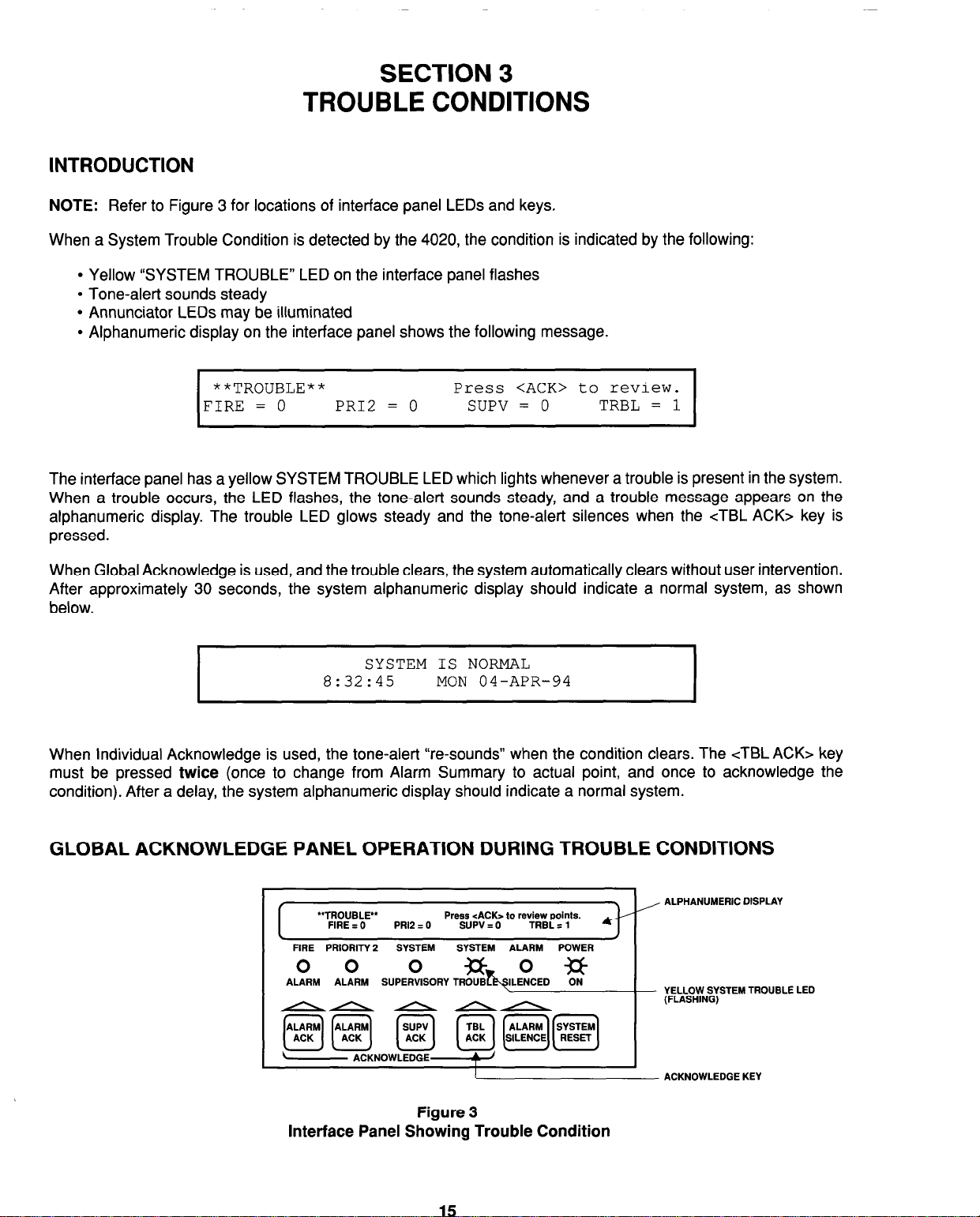
Alphanumeric display on the interface panel shows the following message.
**TROUBLE**
FIRE = 0 PRI2 = 0 SUPV = 0
Press <ACK> to review.
TRBL = 1
The interface panel has a yellow SYSTEM TROUBLE LED which lights whenever a trouble is present in the system.
When a trouble occurs, the LED flashes, the tone-alert sounds steady, and a trouble message appears on the
alphanumeric display. The trouble LED glows steady and the tone-alert silences when the cTBL ACK> key is
pressed.
When Global Acknowledge is used, and the trouble clears, the system automatically clears without user intervention.
After approximately 30 seconds, the system alphanumeric display should indicate a normal system, as shown
below.
SYSTEM IS NORMAL
8:32:45
When Individual Acknowledge is used, the tone-alert “re-sounds” when the condition clears. The cTBL ACK> key
must be pressed twice (once to change from Alarm Summary to actual point, and once to acknowledge the
condition). After a delay, the system alphanumeric display should indicate a normal system.
MON 04-APR-94
GLOBAL ACKNOWLEDGE PANEL OPERATION DURING TROUBLE CONDITIONS
, @j[Gg Ia] [-iq~][~]
“TROUBLE”
I
FIRE I 0 PR12 = 0 SUPV = 0 TRBL = 1
FIRE PRIORITY 2 SYSTEM SYSTEM ALARM POWER
00 0
Press cACK> to review points.
%b.,o,,D ?it ALARM ALARM SUPERVISORYTROUB
AA/\&n
- ACKNOWLEDGE
Figure 3
Interface Panel Showing Trouble Condition
. /
4--
ALPHANUMERIC DISPLAY
YELLOW SYSTEM TROUBLE LED
(FLASHING)
ACKNOWLEDGE KEY
Page 24
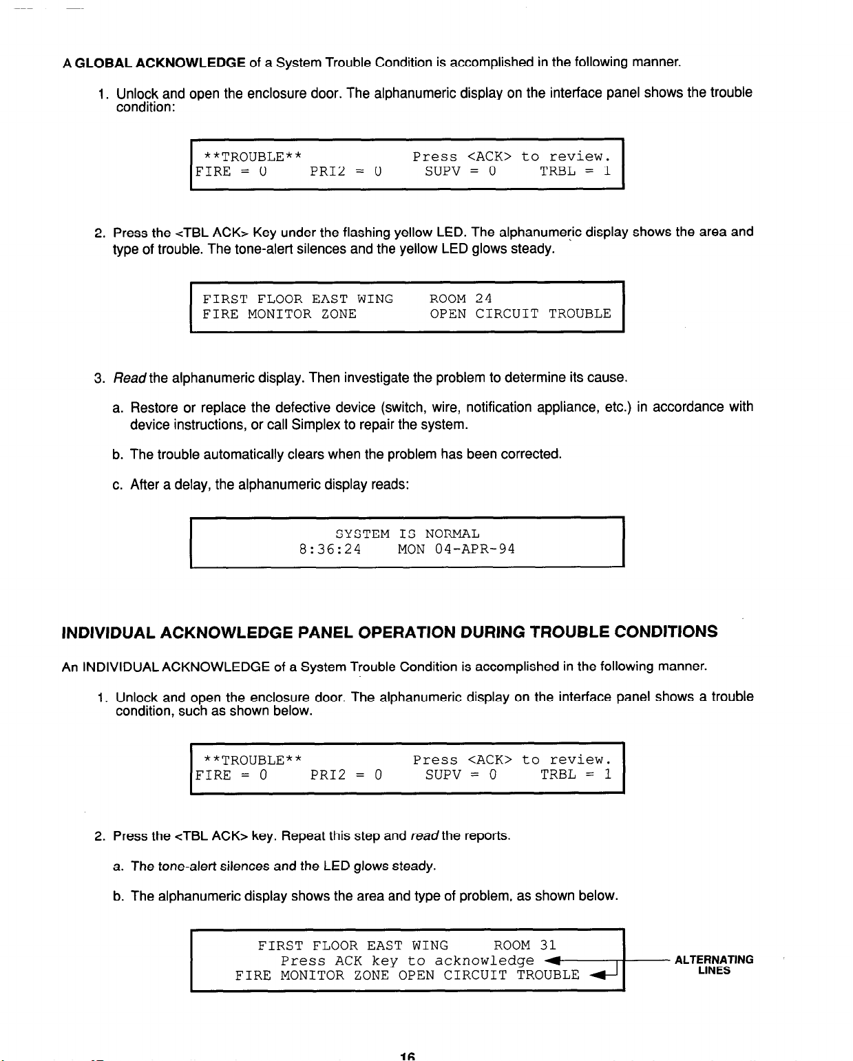
A GLOBAL ACKNOWLEDGE of a System Trouble Condition is accomplished in the following manner.
www.BevanSecurity.Com
1. Unlock and open the enclosure door. The alphanumeric display on the interface panel shows the trouble
condition:
**TROUBLE** Press <ACK> to review.
FIRE = 0
I
2. Press the cTBL ACK> Key under the flashing yellow LED. The alphanumeric display shows the area and
type of trouble. The tone-alert silences and the yellow LED glows steady.
FIRST FLOOR EAST WING ROOM 24
FIRE MONITOR ZONE OPEN CIRCUIT TROUBLE
I
3. Read the alphanumeric display. Then investigate the problem to determine its cause.
a. Restore or replace the defective device (switch, wire, notification appliance, etc.) in accordance with
device instructions, or call Simplex to repair the system.
b. The trouble automatically clears when the problem has been corrected.
PR12 = 0
SUPV = 0
TRBL = 1
I
c. After a delay, the alphanumeric display reads:
SYSTEM IS NORMAL
8:36:24 MON 04-APR-94
INDIVIDUAL ACKNOWLEDGE PANEL OPERATION DURING TROUBLE CONDITIONS
An INDIVIDUAL ACKNOWLEDGE of a System Trouble Condition is accomplished in the following manner.
1. Unlock and open the enclosure door. The alphanumeric display on the interface panel shows a trouble
condition, such as shown below.
**TROUBLE**
FIRE = 0
I
2. Press the <TBL ACK> key. Repeat this step and read the reports.
a. The tone-alert silences and the LED glows steady.
PR12 = 0
Press <ACK> to review.
SUPV = 0
TRBL = 1
I
b. The alphanumeric display shows the area and type of problem, as shown below.
FIRE MONITOR ZONE OPEN CIRCUIT TROUBLE
FIRST FLOOR EAST WING
Press ACK key to acknowledge
Page 25

3. Read the alphanumeric display. Then, investigate the trouble to determine its cause. Restore or replace
www.BevanSecurity.Com
the defective device (switch, wire, notification appliance, etc.) in accordance with device instructions.
NOTE: When the trouble clears, the trouble LED flashes and the tone-alert sounds steady.
4. Press the cTBL ACK> key under the flashing SYSTEM TROUBLE LED. The alphanumeric display shows
the system status.
5. Press the cTBL ACK> key under the yellow SYSTEM TROUBLE LED again. After a delay, the
alphanumeric display reads:
SYSTEM IS NORMAL
8:41:43
MON 04-APR-94
ESSENTIAL TROUBLE CONDITION KEYS
The essential keys for trouble conditions are the Trouble Acknowledge cTBL ACK> and the <SYSTEM RESET>
keys. The remaining keys are concealed by the access door and are associated with advanced functions of the
system. (See Section 8, Advanced Functions.) Use of these keys require advanced user skills. These keys may be
passcode protected. (See Operator Access Levels, Section 8, and Log In Procedure, Section 1.)
TROUBLE ACKNOWLEDGE KEY
The cTBL ACK> key is used to scroll through the various displays on the alphanumeric display. It also controls the
Trouble LEDs and the tone-alert. The <TBL ACK> key is located directly under the SYSTEM TROUBLE LED.
Pressing the cTBL ACK> key (twice for Individual Acknowledge or once for Global acknowledge) causes the LED
to change from flashing ON to steady ON, silences the tone-alert, and causes the following to occur:
l
Selects the next unacknowledged trouble point and display it on the alphanumeric display (Individual
Acknowledge)
l
Acknowledges the displayed point or acknowledges all points on the list (Global Acknowledge)
l
Silences signals programmed to follow the cTBL ACK> key
l
Scrolls the points chronologically after all have been acknowledged.
If the <TBLACK> key is passcode protected, you cannot use this key to acknowledge troubles unless you have the
required access level. (See Operator Access Levels, Section 8, and Log In Procedure, Section 1.)
There are two types of acknowledges for the 4020 system: Global Acknowledge and Individual Acknowledge. Each
acknowledge type operates with the System Trouble Condition in the following manner.
l
Global Acknowledge
- When Global Acknowledge is used on the 4020 system, a single key press of the
<TBL ACK> key acknowledges all troubles in the system. If status change information is required, you may
review this data (after a 30-second delay) by pressing the <TBL ACK> key and reading the total number of
troubles on the alphanumeric display.
l
Individual Acknowledge (For NFPA 72 Proprietary Receiver Requirements) - If a trouble condition has
been acknowledged with the cTBL ACK> key and further unacknowledged conditions remain in the system,
the tone-alert continues sounding and the next status change shows on the alphanumeric display. This
process repeats until all changes are acknowledged. When this occurs, the tone-alert silences.
17
Page 26

SYSTEM RESET KEY
www.BevanSecurity.Com
NOTE: The <SYSTEM RESET> key is also described in Section 2 of this document.
Normally, trouble points do not require acknowledgment of the cleared condition. If the system does not clear, read
the display. Then check for devices still in trouble (pull stations, smoke detectors etc.). Call Simplex to repair the
system.
Some troubles latch until they are reset manually or are reset by pressing the <SYSTEM RESET> key. These
troubles include Style D (“Class A”) initiating device circuit troubles, and reverse polarity city circuit trouble
conditions.
If a monitor point intermittently toggles into trouble, or will not reset, you may choose to disable that point, using the
procedure given in the following paragraphs.
IF THE TROUBLE DOES NOT RESET
If a trouble condition does not clear after a device has been restored, press the <SYSTEM RESET> key. If the
condition does not clear, or continually toggles troubles, the trouble has not been corrected. Read the alphanumeric
display on the interface panel to determine the location and type of device/point with the trouble condition. You may
choose to either disconnect the device, or to disable the trouble point by performing the Disable Procedure given in
the following paragraphs.
HOW TO DISABLE A POINT WITH A TROUBLE CONDITION
CAUTION
DISABLING A POINT CAUSES THAT POINT TO NOT REPORT ALARM CONDITIONS OR OTHER
STATUS CHANGES. A POINT SHOULD NOT BE DISABLED UNLESS IT IS CLEARLY UNDERSTOOD
THAT FIRE DETECTION OR SECURITY FOR THE AREA OF THE BUILDING COVERED BY THAT
POINT WILL BE LOST. APPROPRIATE STEPS MUST BE TAKEN TO PROVIDE ALTERNATE MEANS
OF PROTECTION FOR THAT AREA OF THE BUILDING WHILE THE POINT IS DISABLED.
If a point does not reset, you may disable the point causing the trouble condition. However, this point must first be
identified. Press the cTBL ACK> key, and read the alphanumeric display on the interface panel. Then disable the
trouble point with the <DISABLE> key. If the <DISABLE> key is passcode protected, perform the Log In Procedure
before performing the Disable Procedure.
Note that the <DISABLE> key press removes power to any displayed monitor point. Thus, disabling a point causes
a trouble condition on the individual zone.
To disable a point, perform the following procedure.
1. Open the interface panel access door.
2. Press the cTBL ACK> key until the point to be disabled is shown on the alphanumeric display, as shown
below.
SECOND FLOOR EAST WING ROOM 24
PULL STATION
I
OPEN CIRCUIT TROUBLE
Page 27

3. Press the <DISABLE> key. The alphanumeric display shows the following message.
www.BevanSecurity.Com
Press <ENTER> to DISABLE
I/O:
I
NOTE: XX = the point to be disabled.
4. Press the <ENTER> key. The alphanumeric display shows the action taken.
ACTION TAKEN
I
NOTE: The system indicates a trouble condition each time a point is disabled. Press the <TBL ACK> key
as required.
5. Repeat steps 2 through 4 above to disable additional points.
IOXX
I
I
IMPORTANT
REPAIR/REPLACE THE FAILED CIRCUIT/DEVICE AS SOON AS POSSIBLE. ONCE REPAIRED, THE
DISABLED POINT SHOULD BE ENABLED AS SOON AS POSSIBLE. (See Section 9, How To Enable A
Disabled Point.)
TROUBLE INDICATIONS FOR TrueAlarm” SENSORS
INTRODUCTION
The devices that are used for the TrueAlarm’” operation are considered sensors instead of detectors, because these
devices do not determine alarm conditions. The TrueAlarmTM smoke sensor is a measuring device that sends data
regarding smoke density to the 4020 control panel. The TrueAlarmTM heat sensor operates in a similar fashion, but
sends temperature data instead of smoke density data. The 4020 uses this data to determine whether a trouble has
occurred. This basic operational difference is the key to TrueAlarm’” operation.
The TrueAlarm” sensor has two automatic trouble indications:
l
Dirty, and
. Excessively Dirty.
A “Smoke Detector Dirty” trouble condition is reported any time the average value on an individual sensor reaches
a set threshold value. At this time, the 4020 is still compensating for environmental factors and is holding the set
sensitivity level.
A”Smoke Detector Excessively Dirty” trouble condition is reported anytime the average value of an individual sensor
reaches a higher than threshold level. At this point, the 4020 can no longer compensate for environmental factors,
and the sensitivity level will begin to drift. Although an “excessively dirty” trouble is reported, the sensor will continue
to operate and will report an alarm condition if one is detected.
In addition to the two automatic trouble conditions, the 4020 software includes a pre-programmed digital pseudo
point (P132, Sensor Almost Dirty Log Enable) that can be turned ON at the front panel to allow a TrueAlarm” sensor
that is within 10 analog units of being a “dirty” sensor to report as if it were one. This is useful when maintenance is
being scheduled for dirty sensors, as it provides a means of seeing if other sensors are approaching a dirty state.
19
Page 28

Once a minute, the 4020 software performs a self-alarm test of each TrueAlarm’” sensor. The self-alarm test raises
www.BevanSecurity.Com
the value of each sensor to a value that simulates an alarm condition. If the sensor reports back a value that is not
within the alarm range, a “self-test abnormal” trouble will be displayed for that specific sensor.
The following paragraphs discuss the responsibilities of 4020 system operators when these trouble indications
occur.
ALMOST DlRTY INDICATION
Using the front panel keypads, it is possible for a SIMPLEX Field Service representative to turn on a system point
that allows an “almost dirty” sensor to report a trouble. Although the “almost dirty” sensor is holding its sensitivity
level, the 4020 operator can schedule maintenance for the sensor before the dirty sensor trouble occurs.
DIRTY INDICATION
A “Dirty” indication means that the sensor is holding its sensitivity level, but that the 4020 operator should schedule
maintenance for the sensor. Clean the sensor as required and, if necessary, call Simplex for service.
EXCESSWEL Y DIRTY INDICATION
The “Excessively Dirty” indication means that the sensor is no longer compensating for dirt and dust. Because false
alarms are possible with this condition, sensors must be cleaned as soon as possible. If necessary, call Simplex for
service.
SELF-TEST ABNORMAL INDICATION
All 4020 system sensors are automatically tested once every minute. If a sensor fails to report properly to the 4020
master controller, a “self-test abnormal” condition occurs. Since the sensor is not working properly, it must be
replaced. Replace it, or call Simplex for service.
Page 29

SECTION 4
www.BevanSecurity.Com
SUPERVISORY CONDITIONS
INTRODUCTION
A System Supervisory Condition is used to indicate the operative condition of Automatic Sprinkler Systems and
other systems used for the protection of life and property. A Supervisory Condition may indicate that one of these
systems is inoperative.
NOTE: Refer to Figure 4 for locations of interface panel LEDs and keys.
When a System Supervisory Condition is detected by the 4020, the condition is indicated by the following:
l
Yellow “SYSTEM SUPERVISORY” LED is flashing
l
Tone-alert is on steady
. Annunciator LEDs may illuminate
l
Alphanumeric display on the interface panel shows the following:
**SUPERVISORY**
FIRE = 0
PR12 = 0
Press <ACK> to review.
SUPV = 1
TRBL = 0
The panel has one yellow SYSTEM SUPERVISORY LED which lights when a supervisory condition is present in
the system. When such a condition occurs, the LED flashes, the tone-alert is ON steady, and a supervisory message
is displayed by the alphanumeric display on the interface panel. When the &UPV ACK> key is pressed, the
SYSTEM SUPERVISORY LED flash becomes a steady glow, and the tone-alert silences.
GLOBAL ACKNOWLEDGE PANEL OPERATION DURING SUPERVISORY CONDITIONS
“SUPERVIsoRY*’
FIRE I 0 PRl2 IO
FIRE PRIORITY 2
0 0
ALARM ALARM
AI\&
SYSTEM
Press cACK> to revview.
SUPV I1
SYSTEM ALARM POWER
TRBL = 0
4-T
ALPHANUMERIC DISPLAY
YELLOW SYSTEM SUPERVISORY LED
(FLASHING)
fE][i%i) m
ACKNOWLEeE-
Interface Panel Showing System Supervisory Condition
A GLOBAL ACKNOWLEDGE of a System Supervisory Condition is accomplished in the following manner.
Figure 4
21
Page 30

1. Unlock and open the enclosure door. The alphanumeric display on the interface panel shows the
www.BevanSecurity.Com
supervisory condition.
**SUPERVISORY**
FIRE = 0
I
2.
Press the <SUPV ACK> key under the flashing yellow LED. The alphanumeric display shows the area and
type of condition. The tone-alert silences and the yellow LED glows steady.
REVERE BASEMENT NORTH WING
SPRINKLER MONITOR ABNORMAL
I
L
3. Read the alphanumeric display. Then, investigate the condition to determine its cause.
a. Restore or. replace the defective device (switch, wire, notification appliance, etc.) in accordance with
device instructions, or call Simplex to repair the system.
b. The supervisory condition automatically clears when the problem has been corrected.
c. After a delay, the alphanumeric display reads:
PR12 = 0 SUPV = 1
SYSTEM IS NORMAL
8:36:24
Press <ACK> to review.
TRBL = 0
ROOM 31
MON 04-APR-94
I
I
1
INDIVIDUAL ACKNOWLEDGE PANEL OPERATION DURING SUPERVISORY CONDITIONS
An INDIVIDUAL ACKNOWLEDGE of a System Supervisory Condition is accomplished in the following manner.
1. Unlock and open the enclosure door. The alphanumeric display shows a Supervisory Condition, such as
shown below.
**SUPERVISORY**
FIRE = 0 PR12 = 0
I
2. Press the cSUPV ACK> key. Repeat this step and read the reports.
a. The tone-alert silences and the LED glows steady.
Press <ACK> to review.
SUPV = 1
TRBL = 0
I
Page 31

b. The alphanumeric display shows the area and type of problem or condition, as shown below.
www.BevanSecurity.Com
FIRST FLOOR EAST WING
Press <ACK> key to acknowledge
I
FIRST FLOOR EAST WING
FIRE PUMP MONITOR
I
3. Read the alphanumeric display. Then, investigate the trouble or condition to determine its cause. Restore
or replace the defective device (switch, wire, notification appliance, etc.) in accordance with device
instructions.
NOTE: When the Supervisory Condition clears, the SYSTEM SUPERVISORY LED flashes and the tone-
alert sounds steady.
4. Press the &UPV ACK> key under the flashing SYSTEM SUPERVISORY LED. The alphanumeric display
shows the system status.
5. Press the cSUPV ACK> key again. After a delay, the alphanumeric display reads:
SYSTEM IS NORMAL
8~41~43
ROOM 31
ROOM 31
MON 04-APR-94
RUNNING
I
ESSENTIAL SUPERVISORY CONDITION KEYS
The essential key for supervisory conditions is the &UPV ACK> key. The remaining keys are concealed by the
access door and are associated with advanced functions of the system. (See Section 9, Advanced Functions.)
SUPERVISORY ACKNOWLEDGE KEY
The &UPV ACK> key is used to Scroll through the various data fields on the alphanumeric display. It also controls
the SUPERVISORY LED and the tone-alert. The &UPV ACK> key is located directly under the SUPERVISORY
LED. Pressing the cSUPV ACK> key (twice for Individual Acknowledge or once for Global Acknowledge) causes the
LED to change from flashing ON to steady ON, and silences the tone-alert. The &UPV ACK> key press does the
following:
l
Selects the next unacknowledged supervisory point and shows it on the display (Individual Acknowledge)
l
Acknowledges the displayed point or acknowledges all points on the list (Global Acknowledge)
l
Scrolls the points chronologically after all points have been acknowledged.
NOTE: The &UPV ACK> key may be passcode protected. If you do not have the required access level, you will
not be able to acknowledge supervisory conditions. (See Operator Access Levels, Section 8, and the Log
In Procedure, Section 1, for details.)
23
Page 32

IThere are two types of acknowledges for the 4020 system: Global Acknowledge and Individual Acknowledge. Each
www.BevanSecurity.Com
acknowledge type operates with the Supervisory Condition in the following manner:
l
Global Acknowledge
- When Global Acknowledge is used on the 4020 system, a single key press of the
<SUPV ACK> key acknowledges all supervisory changes in the system. If status change information is
required, you may review this data (after a 30-second delay) by pressing the &UPV ACK> key and reading
the total number of supervisory changes on the alphanumeric display.
l
Individual Acknowledge (For NFPA 72 Proprietary Receiver Requirements) - If a supervisory condition has
been acknowledged with the cSUPV ACK> key and further unacknowledged conditions remain in the system,
the tone-alert continues to sound and the next status change is shown on the alphanumeric display. This
process repeats until all changes are acknowledged. When this occurs, the tone-alert silences and the highest
priority acknowledge change appears on the display.
24
Page 33

SECTION 5
www.BevanSecurity.Com
RS-232 INTERFACE
INTRODUCTION
Two RS-232 ports are available on the RS232 interface card. The RS-232 interface option supports both printers
and video terminals to annunciate alarm, supervisory, and trouble conditions.
RS-232 PORT ACCESS LEVELS
The interface panel, and each RS-232 interface port configured for a video terminal, are programmed to allow
certain operations at each access level. You must be “logged in” at the required access level or higher to perform
the various system operations. Up to 20 operators are allowed to log in at the various passcode access levels. The
number of operators, passcode access levels, and the allowed operations are programmed into the system,
dependant on the customer requirements.
If a port is not configured to annunciate a class of events, such as supervisory conditions, you will not be able to
acknowledge those points with the video terminal keyboard - even though the video terminal is connected to that
port - regardless of the passcode level entered. Table 1 lists the default protection levels for the RS-232 interface.
These levels are programmed to meet customer requirements.
Table 1
RS-232 Interface Default Protection Levels
EVENT
Alarm Silence
System Reset
Alarm Acknowledge
Trouble Acknowledge
Supervisory Acknowledge
Clear Historical Logs
Alarm
Trouble
NOTE: Access level from the RS-232 video terminal/keyboard port is separate from the interface panel access
level.
DEFAULT
3
3
VIDEO TERMINAL
The video terminal, or CRT (for the Cathode Ray Tube video display), provides annunciation and system control
from the CRT display keyboard. If your system includes a Video Terminal, see Pub. No. FA4-31-306 for a complete
listing of CRT operating commands.
25
Page 34

CRT FUNCTION KEY DEFINITIONS
www.BevanSecurity.Com
The Function Keys on the CRT keyboard are used to control the various 4020 operations. Table 2 defines the various
keys and their uses.
Table 2
Function Key Definitions
l
FUNCTION KEY
F2
F3
F18
F19
PFl
PF2
PF3
PF4
CTRL W
* For Micro-Term terminals. Other units may vary. See user manual for your terminal.
SET-UP PROCEDURE
The CRT must be set-up correctly in order to receive and transmit data. An operator may enter the set-up mode to
verify proper configuration. However, set-up procedures are performed by Simplex personnel and should not
normally be performed by operators. (See publication FA4-1 l-224 for CRT set-up parameters.)
Print Screen
(Printer Required)
Set-Up
Main Menu
Historical Log Menu
Acknowledge Key
Alarm Silence
System Reset Key
Log In/Log Out Key
Refreshes Current Screen
DEFINITION
CRT SCREEN DISPLAYS
A variety of CRT screen displays are used to support 4020 operations. Header information is displayed on the first
three lines of the screen. The first line shows the time on the left, custom banner in the center, and the operator on
the right side of the screen. The second line shows the date on the left and the current access level on the right. The
third line shows the overall 4020 system status. Prompt/Message information is shown on all screens. The bottom
line displays prompts, help messages, and error messages. These screens tell you what to do and when to do it.
CRT screen displays are shown in Figures 5 through 9.
CRT MAIN MENU SCREEN
The CRT Main Menu Screen (Figure 5) is the first screen to appear after power is applied to the system. From the
Main Menu Screen, you can display various system information screens. Items 1 through 6 are the available choices
within this menu. View any item by either moving the cursor to the selection or by typing the item number and then
pressing the <Enter> key.
Page 35

Figure 5 shows the cursor positioned on Item 1. To select Item 4 (Alarm Historical Log), move the cursor to Item 4
www.BevanSecurity.Com
with the cursor control keys, or type the number c4> key and press the <Enter> key.
_-_-_-_-_-_-_-_-_--- - - - - ---- - --_-____
TIME: 10:05:24 PM
DATE: MON 04 APR 94
---------------------------------~-~~
-------------------------------------
PORT 1 - SECURITY OFFICE
4020 F/A SYSTEM
SYSTEM IS NORMAL
USER: 1
ACCESS: 1
4020 FIRE ALARM OPERATOR INTERFACE
MAINMENU
L. Alarms -
Display any Current Alarms
2. Supervisories - Display any Current Supervisories
3. Troubles - Display any Current Troubles
4. Alarm Historical Log
5. Trouble Historical Log
6. System Functions
Select Option or PFl to Acknowledge > 1
Figure 5
CRT Main Menu Screen
ACKNOWLEDGE SCREEN
The entire 4020 system (including the CRT ports) is configured as either a Global Acknowledge system or as an
Individual Acknowledge system. If the system is configured as a Global Acknowledge system, one press of the
cPFl> key acknowledges all abnormal conditions that can be annunciated by the port. When the system is
configured as an Individual Acknowledge system, the Acknowledge key, <PFl>, must be pressed to acknowledge
each condition change.
All conditions which can be displayed at the CRT can be acknowledged at the CRT, provided that you have logged
in at a sufficient access level. A tone on the CRT sounds to indicate unacknowledged conditions. (The tone can be
silenced with the cPF1 z- key.) When an abnormal condition occurs, you must select the appropriate acknowledge
screen. The Header information on the screen indicates the number of abnormal conditions which can be
annunciated by the CRT, and not necessarily the total number of abnormal conditions in the system. To acknowledge
an abnormal condition, press the <PFl> key while in the acknowledge screen. The displayed condition will stop
flashing, but will still indicate the abnormal condition. When all abnormal conditions have been acknowledged, you
can return to the Main Menu by pressing the <F18> key.
As with the operator interface, alarms have priority over supervisory and trouble conditions. Multiple conditions are
displayed in chronological order. Should multiple unacknowledged conditions occur, no unacknowledged event is
allowed to scroll off the screen. If more unacknowledged conditions exist in the system than can fit on the screen,
the “oldest” unacknowledged point is displayed first. After that condition is acknowledged, it scrolls off the top of the
screen and is replaced by the next oldest condition.
27
Page 36

The acknowledge screens are dynamic, and information is updated once per second. Follow the prompts at the
www.BevanSecurity.Com
bottom of the screen (shown in Figure 6) to silence signals (<PF2> key), or to reset the system (<PF3> key). When
the system has reset, press the cPFl> key to acknowledge the condition change.
________-_____-----------------------
TIME: 10:18:15 PM
DATE:
________-____-_- -_-__-_- -_- -_- --- ---________-______--_-_-----------------
10:09:27 pm
MON 04 APR 94 PORT 1 - SECURITY OFFICE
FIRE ALARMS=1
PRIORITY 2=0 SUPERVISORY=0 TROUBLES=0
MON 04 APR 94
4020 F/A SYSTEM USER: 1
ACCESS: 1
SECOND FLOOR, EAST WING,
ROOM 14
PULL STATION FIRE ALARM
PFl=ACK,
LOG IN SCREEN
It may be necessary to increase your CRT/Keyboard access level in order to acknowledge an abnormal condition.
With the Main Menu displayed on the CRT screen, press the cPF4> key. A prompt will appear on the screen to “Enter
your passcode”. (See Figure 7.)
Up to 19 passcodes are available to support user requirements. The passcode, in conjunction with the access level
entered, determines if the operator can perform the required system functions.
Enter yourLpasscode, and press the <Enter> key. The user number will appear in the Header information at the top
right corner of the screen. The operator access level is also displayed. Your passcode is not shown on the screen
for security reasons. Instead, the screen shows “XXX”.
__-__-__-_______-___-----------------
PF2=Silence,
TIME: 10:06:31 PM
DATE: MON 04 APR 94 PORT 1 - SECURITY OFFICE ACCESS: 1
-_- -_-__-____________- - -____- - - - - ---__-___________________ - -____- - - - - ----
PF3=System Reset, PF4=Login, F18=Main Menu
Figure 6
CRT Acknowledge Screen
4020 F/A SYSTEM
SYSTEM IS NORMAL
USER: 1
4020 FIRE ALARM OPERATOR INTERFACE
MAINMENU
1. Alarms - Display any Current Alarms
2. Supervisories - Display any Current Supervisories
3. Troubles -
Display any Current Troubles
4. Alarm Historical Log
5. Trouble Historical Log
6. System Functions
Enter your passcode or ENTER to log out> XXX
Figure 7
CRT Log In Screen
Page 37

HISTORICAL LOG SCREEN
www.BevanSecurity.Com
The Historical Logs are formatted differently from the CRT Acknowledge Screens, As on the operator interface
panel, the Historical Logs are displayed with any entry number, followed by a time tag and the actual event.
The Historical Log shows all events in the 4020 system log, not just those events annunciated on the CRT. These
screens are not dynamic. They display only historical data.
To view the Historical Log Screens, you must select the type of historical log from the CRT Main Menu Screen
(Figure 7). These options are the Alarm Historical Log and the Trouble Historical Log. Select the desired function
either by placing the screen cursor on the function name, or by pressing either the <4> key or the <5s key. Then,
press the <Enter> key. A typical ALARM Historical Log is shown in Figure 8.
--_---_--------_---_---~------------~
TIME: 10:18:15 PM 4020 F/A SYSTEM
DATE: MON 04 APR 94 PORT 1 - SECURITY OFFICE
-------------------------------------
---------------------------~---------
FIRE ALARMS=4
ENTRY 1 10:09:27 pm MON 04 APR 94
PRIORITY 2=0 SUPERVISORY=0 TROUBLES=0
SECOND FLOOR, EAST WING, ROOM 14
USER: 1
ACCESS: 1
PULL STATION FIRE ALARM
ENTRY 2 10:11:15
pm
MON 04 APR 94 SECOND FLOOR, EAST WING, ROOM 12
MONITOR ZONE FIRE ALARM
ENTRY 3 10:12:23 pm MON 04 APR 94 SECOND FLOOR, EAST WING, HALL
MdNITOR ZONE.FIRE ALARM
ENTRY 4
10:13:45 pm MON 04 APR 94
SECOND FLOOR, EAST WING,
ROOM 15
MONITOR ZONE FIRE ALARM
F18=Main Menu, F19=Log Menu
I
Figure B
CRT Alarm Historical Log Screen
STATUS SCREEN
When Menu Option 1, 2, or 3 is selected, the screen displays current abnormal system conditions. The data
displayed is updated once every second. The time and date information indicates when the point status changed
from normal to abnormal condition.
The screen format is the same as the format for the ‘Acknowledge Screens. Flashing entries indicate
unacknowledged entries. Figure 9 shows the CRT Status Screen displaying the Current Trouble List.
-_----------------------------e---v--
TIME: 11:15:11 PM 4020 F/A SYSTEM
DATE: MON 04 APR 94 PORT 1
___--__--___-__--__------------------
___-___-___--------------------------
FIRE ALARMS=0 PRIORITY 2=0
- SECURITY OFFICE ACCESS: 1
SUPERVISORY=0 TROUBLES=4
10:19:29 pm MON 04 APR 94 SECOND FLOOR, EAST WING, ROOM 14
SIGNAL CIRCUIT OPEN CIRCUIT TROUBLE
10:21:06 pm MON 04 APR 94 MASTER BATTERY BACKUP
BATTERY STATUS IS TROUBLE
10:27:09 pm
MON 04 APR 94
SYSTEM/TIME INVALID OR NOT SET
TROUBLE
POINT ABNORMAL
10:51:00 pm MON 04 APR 94 SECOND FLOOR, EAST WING, ROOM 15
FIRE MONITOR ZONE DISABLE TROUBLE
USER: 1
PFl=ACK, PF2=Silence, PF3=System Reset, PF4=Login, F18=Main Menu
Figure 9
CRT Status Screen
Page 38

SYSTEM PRINTER
www.BevanSecurity.Com
The 4020 uses a printer to provide a hardcopy of the system’s current status. The 4020 system supports both DC
and AC printers.
The DC printer prints alarms in red ink; troubles and supervisory conditions in black ink. A DC printer printline is 40
characters long. A typical DC printer printout is shown in Figure 10.
10:09:27 pm
MON
04
APR 94
2ND FLOOR FAST WING, ROOM 14
PULL STATION
FIRE ALARM
10:10:36 pm MON 04 APR 94
ALARM ACKNOWLEDGED AT MAIN PANEL
10:15:12 pm MON 04 APR 94
ALARM SILENCE IN PROGRESS
10:16:09 pm MON 04 APR 94
SIGNALS SILENCED AT MAIN PANEL
10:17:10 pm MON 04 APR 94
SYSTEM RESET IN PROGRESS AT MAIN PANEL
10:18:12 pm MON 04 APR 94
SYSTEM RESET IN PROGRESS
10:19:33
pm
MON 04 APR 94
2ND FLOOR EAST WING, ROOM 14
PULL STATION
NORMAL
10:19:45 pm MON 04 APR 94
2ND FLOOR EAST WING, ROOM 14
NO ALARMS PRESENT,
40-Character Line Width Printout
The AC printer prints only in black, with line widths of 80 characters. A typical AC printer printout is shown in Figure
11.
10:09:27 pm
MON
04 APR 94
2ND FLOOR EAST WING, ROOM 14
PULL STATION
10:10:36 pm
10:15:12 pm
10:16:09 pm
MON 04 APR 94
MON 04 APR 94
MON 04 APR 94
10:17:10 pm MON 04 APR 94
10:18:12 pm MON 04 APR 94
10:19:33 pm
MON 04 APR 94
ALARM ACKNOWLEDGED AT CRT
ALARM SILENCE IN PROGRESS
SIGNALS SILENCED AT CRT
SYSTEM RESET IN PROGRESS AT CRT
SYSTEM RESET IN PROGRESS
2ND FLOOR EAST WING, ROOM 14
PULL STATION
10:19:45 pm
MON 04 APR 94
2ND FLOOR EAST WING, ROOM 14
NO ALARMS PRESENT,
SYSTEM RESET COMPLETE
Figure 10
FIRE ALARM
NORMAL
SYSTEM RESET COMPLETE
Figure 11
BO-Character Line Width Printout
Page 39

SECTION 6
www.BevanSecurity.Com
NETWORK INTERFACE
INTRODUCTION
The Network Interface Option allows the 4020 to communicate with other FA panels or with a 2120 Multiplex System
(see Network Concepts [NET-91 -5001).
Note: The 4020 acts as a transponder when connected to a 2120.
NETWORK (OR 2120) OPERATION DURING Walk Test’”
Status changes occurring as a result of a Walk Test’” operation in a networked system are not communicated to
other members of the network (or a 2120). The Walk Test’” is strictly a local 4020 operation. See Section 10 for Walk
Test’” procedures.
31
Page 40

www.BevanSecurity.Com
Page 41

SECTION
www.BevanSecurity.Com
7
MAPNET II@ ADDRESSABLE INTERFACE
INTRODUCTION
Addressable device communications operate via the Simplex Multiple Addressable Peripheral Network (MAPNET
If=). Using a two-wire circuit, individual initiating devices such as automatic smoke detectors, TrueAlarm” smoke
sensors, manual fire alarm boxes, and sprinkler flow switches can communicate their exact identity and status. This
addressability allows the location and condition of each device to be displayed on the interface panel and on the
system annunciators. In addition, notification appliance circuits (horns, bells, strobes, etc.) as well as other control
circuits (fans, dampers, etc.) may be individually controlled. Acombined total of 127 addressable monitor and control
devices may be intermixed on the same pair of wires. If Zone Adaptor Modules (ZAMs) are used, non-addressable
initiating devices can be connected to the MAPNET II@ circuit. The MAPNET II@ option allows the use of addressable
devices and TrueAlarm” sensors with the 4020 system.
TrueAlarm” SYSTEM OPERATION
The MAPNET II@ Controller can communicate with smoke density and temperature sensing devices called
TrueAlarm” Sensors. ATrueAlarm’” sensor measures smoke density, but has no self-contained alarm set point. The
alarm set point is programmed into the 4020. Thus, the alarm decision is made by the 4020, rather than by the
sensor.
Every four seconds, each smoke sensor transmits an output value based on its smoke chamber condition. The 4020
system maintains a current value, peak value, and an average value of each sensor’s output. Status is determined
by comparing the current sensor value to its average value. Tracking this average value as a continuously shifting
reference point filters out the environmental factors that cause shifts in sensitivity. Each sensor’s sensitivity can be
field-programmed at the 4020 panel for different levels of smoke obscuration (in percent). Sensor sensitivity can be
individually varied automatically by time of day, typically more sensitive at night and less sensitive during daytime
hours. In order to evaluate whether the sensitivity should be revised, the peak value that is stored in memory can
be read and compared to the alarm threshold directly in percent.
TrueAlarm’” operation gives the 4020 system the ability to automatically indicate when a sensor is dirty and when it
is excessively dirty. The NFPA 72 requirement for a test of the sensitivity range of the sensors is fulfilled by the 4020
system’s ability to maintain the sensitivity level of each sensor. Additionally, a “two-stage” alarm operation can be
programmed in the 4020 panel. For example, a one-percent smoke obscuration reading could cause a local
indication allowing the building security staff to investigate, while a three-percent obscuration report could
immediately initiate a system alarm.
TrueAlarm” heat sensors provide reading of local temperatures. For fire sensing, rate-of-rise sensing can be
selected as either 15°F or 20°F per minute, with an independent fixed limit of 135’F. For general temperature
sensing, a set point can be selected from 32’F to 158°F and the local temperature readings can be used to warn of
potential problems. The temperature readings can be programmed to read in either Fahrenheit or Celsius.
Page 42

Sensor data can be displayed on the interface panel LCD, on a remote CRT, or printed on a remote printer. Figure
www.BevanSecurity.Com
12 shows a typical TrueAlarm” status report as it might appear on a CRT screen.
TIME:
DATE: FRI 4 MAR
Zone
Name
_________-______________________________-------------------------------------------Ml-l
Ml-2
Ml-3
Ml-4
Ml-10
Ml-l 1
Press PF3 for next screen OR PF4 to return to menus
With the proper operator access, a TrueAlarm” Service Report can be generated to list the specific details of each
TrueAlarm” device. Figure 13 shows a typical Service Report screen.
2:40:46
94
REPORT 3 :
Custom Label
ANALOG PHOTO - CLEAN ROOM
ANALOG ION - CLEAN ROOM
ANALOG PHOTO - MAIN LOBBY 2.5 NORMAL
ANALOG PHOTO - CONFERENCE ROOM 1
HEAT DETECTOR - GARAGE
ANALOG PHOTO - KITCHEN
Typical TrueAlarm” Status Report Screen
custom title
Port 1 Card 5 A
TRUEALARM STATUS REPORT
Sensitivity Device Status Dirty
2.5
1.3
2.5 NORMAL
135F
2.5 NORMAL
Figure 12
NORMAL
NORMAL
NORMAL
USER: 1
ACCESS: 1
Almost
*YES*
*YES*
TIME: 2:53:27
DATE: FRI 4 MAR 94
REPORT 4 :
____---_-_______________________________--------------------------------
Press PF3 for next screen OR PF4 to return to menus
Custom Label
CLEAN ROOM DEV 1
CLEAN ROOM ION DET DEV 2 1.3/209 94 97l 2%
MAIN LOBBY DEV 3
CONFERENCE ROOM 1 DEV 4
GARAGE
KITCHEN
DEV 10 HEAT DETECTOR
DEV 11
Typical TrueAlarm” Service Report Screen
custom title
Port 1 Card 5 A
TRUEALARM STATUS R.EPORT
Alarm
at: val
2.51135 67 68l
2.5/157 89 891
2.5/161 93 931
135F/253 -
2.5/159 91
Figure 13
USER: 1
ACCESS: 1
Avg Avg Current/ Peak/ State
% alarm
1% 681
0% 891
0% 93l
66/ 69F 631
921 1% 92l
% alarm
1% NOR
lOl/ 1%
0% NOR
0% NOR
67F NOR
1% NOR
NOR
Page 43

The Service Report shown in Figure 13, as well as the Status Report shown in Figure 12, can either be displayed
www.BevanSecurity.Com
on the remote CRT or captured permanently by using a remote printer. This information is available at the interface
panel LCD by identifying the specific point of interest and reading one point at a time.
GENERATING TrueAlarm’” REPORTS
l
Applies only to systems that feature a printer.
To Obtain a TrueAlarm’” Status Report
1. Press the <MENU> key on the DISPLAY/ACTION keypad. Then press the <NEXT> key seven times.
l
The alphanumeric display reads:
Press <NEXT> or <PREVIOUS> to scroll
Report 3:
I
2. Press <ENTER>. Then press <NEXT> twice.
l
The alphanumeric display reads:
TrueAlarm Status Report
I
Press <NEXT> or <PREVIOUS> to scroll
Print Reports?
3. Press <ENTER>.
l
Printer prints out TrueAlarm” Status Report.
To Obtain a TrueAlarm” Service Report
1. Perform Step 1 above. Then press the <ENTER> key once and the <NEXT> key three times.
l
The alphanumeric display reads:
Press <NEXT> or <PREVIOUS> to scroll
Report 4:
2. Press <ENTER>.
l
Printer prints out TrueAlarm” Service Report.
TrueAlarm Service Report
MAPNET 11~ ALPHANUMERIC DISPLAYS
When a MAPNET II@ device changes to an abnormal state, or when you enter a MAPNET II@ device address, the
alphanumeric display shows the current status of the MAPNET II@ device. After entering a MAPNET II@ device
address, press the <FUNCTION> key on the interface panel to display additional information.
For a TrueAlarm’” sensor, device information reported back to the interface panel also includes data about the
condition of the sensor itself. For example, the sensor might report that it is dirty or even excessively dirty.
35
Page 44

MAPNET II@ POINT ADDRESSING
www.BevanSecurity.Com
Each MAPNET II@ device must have a point address in order to communicate with the 4020 system. These point
addresses, along with their custom labels, are located in the Programmer’s Report. The Programmer’s Report
shows the address for each device, separated by hyphens. Hyphens must be used when entering a MAPNET II@
address into the system. An example of a MAPNET II. device address is “Ml -5”. The “Ml fl portion of the address
identifjes the MAPNET 11~ channel, Channel 1. The “5” portion of the address identifies the device number, Device
Number 5. The only valid MAPNET IIQ channels for the 4020 are Channels 1 and 2.
HOW TO DISPLAY A MAPNET II@ SYSTEM POINT
For MAPNET Ileo operations, see Section 8, “How to Use Prefix Keys to Display System Points.” This procedure also
shows the Programmer’s Report for MAPNET Ilc addresses.
WHAT TO DO IF A MAPNET II@J POINT WILL NOT RESET
If a MAPNET ll@~ device will not reset, you may decide to disable the point with the <DISABLE> key. When the disable
procedure is performed, a System Trouble occurs to remind you that the point is disabled. The disable procedure is
the same for all system points (see Section 2, “How to Disable a Point”). Maintenance personnel must be called
immediately to repair the malfunction.
After the MAPNET II@ monitor point is repaired, you can enable the point again (see Section 9, “How to Enable a
Disabled Point”). This procedure is the same for all system points.
Page 45

SECTION 8
www.BevanSecurity.Com
ADVANCED FUNCTIONS
INTRODUCTION
When more involved operator functionality/control is required, simply open the interface panel “Access Door” to
expose the additional keys which are available for advanced functions. Figure 14 shows the interface panel with the
access door open and the advanced function keys displayed.
\,r;7 v v
SYSTEM IS NORMAL
9:2?:4O MON 04-APR.94
Figure 14
Interface Panel Controls and Indicators
I
CONTROL KEYS
Five “CONTROL” keys and their associated LEDs (Figure 15) are located to the left of the interface panel. Normally,
these keys and LEDs are concealed by the access door. A custom label is used to identify the desired function.
Typical functions for these keys are Priority 2 Reset, City Disconnect, Manual Evacuation, Door Holder Bypass, Start
a Drill, Control all Signals, Elevator Capture, Control Air Handling Units, and Manual Control. When a CONTROL
key is pressed, the programmed event occurs.
-CONTROL
ml0
q r
CIEID
cm0
ClElr
Figure 15
CONTROL Keys
OPERATION OF THESE KEYS MAY CAUSE ALARM SIGNALS TO SOUND OR TROUBLE
CONDITIONS TO BE GENERATED BY THE SYSTEM.
CAUTION
37
Page 46

These keys can be pressed anytime, and the key feedback (beep) may be the only acknowledgment of the action.
www.BevanSecurity.Com
Typically, the LED tracks the function and illuminates each time the associated key is pressed.
Use of key functions can be controlled by assigning operator access levels to each key (see “Operator Access
Levels” in this section and “Log In Procedure” in Section 1.)
FUNCTION KEYS
Four function keys (cFl>, <F2>, cF3>, and cF4>) are located directly above the alphanumeric display (see Figure
16). Within the Main Menu options, these key definitions change as required to perform specific actions for selected
Main Menu options. The definitions for each key are shown on the top line of the alphanumeric display as an aid to
the user. A function key does not require any other key to be pressed to activate its function. Pressing a key causes
that key to immediately perform its defined task. Pressing a key which has no defined action for the current function
has no effect. However, the tone-alert acknowledges the key press with a “beep.” These four keys are associated
with advanced functions of the system within the Main Menu options, and within point displays. These keys may be
passcode protected for some of the defined operations.
The cFl>, <F2>, <F3>, and cF4> have extended actions defined during point displays used in conjunction with the
<FUNCTION> key on the DISPLAY/ACTION keypad. The actions vary with the point and status displayed.
7 FUNCTION KEYS 1
SYSTEM IS NORMAL
6:15:43pm MON 04-APR-94
Figure 16
FUNCTION KEYS
HOW TO SET TIME AND DATE
The following is an example of how to use the function keys to set the time and date.
1. Press the <MENU> key on the DISPLAY/ACTION keypad. The following is shown on the alphanumeric
display.
Press <NEXT> or <PREVIOUS> to scroll
Change Access Level?
I
2. Press the <NEXT> key. The following is displayed.
Press <NEXT> or <PREVIOUS> to scroll
Set Time and Date?
I
I
38
Page 47

3. Press the <ENTER> key. The current time and date information is displayed along with instructions.
www.BevanSecurity.Com
Press <FUNC> to change time and date
I
4. Press the <FUNCTION> key on the DISPLAY/ACTION keypad. The cursor, current time and date, and
function key definitions are displayed.
Fl=Left F2=Right F3=Inc F4=Dec
NOTE: The cursor is positioned under the hour. Function key Fl moves the cursor left. Function key F2
moves the cursor right. Function key F3 increases the data above the cursor. Function key F4
decreases the data above the cursor.
5. Use the required Function key to position the cursor under the data to be changed (hour, minutes, seconds,
date of month, month, and year). Day of week is set by the system. Time entered does not start until the
<ENTER> key is pressed.
18:15:43
18:15:43
I
t
CURSOR
MON 04-APR-94
MON 04-APR-94
I
6. Use Function key F3 or F4 to increase or decrease data, as required.
7. When time and date are correct, press the <ENTER> key. The display shows the updated time and date.
The time entered does not start until the <ENTER> key is pressed.
Press <FUNC> to change time and date
18:30:00
HOW TO ESCAPE FROM MENU
To leave the menu, do the following procedure.
1. Press the cCLR> key on the ENTRY keypad. The following is displayed:
Press <NEXT> or <PREVIOUS> to scroll
Select a List of Points?
I
2. Press the -&LR> key again. The following is shown:
MON 04-APR-94
I
SYSTEM IS NORMAL
18:30:43
39
MON 04-APR-94
Page 48

POINT CONTROL WITH THE FUNCTION KEY
www.BevanSecurity.Com
Many of the functions performed from the interface panel control point-specific data. The interface panel
cFUNCTION> key can be used to control points.
The <FUNCTION> key enables the user to view additional status information concerning the point currently
displayed on the alphanumeric display. The point selected on the alphanumeric display can be manually entered
through the ENTRY keypad, or maybe the point displayed because of an abnormal condition. Definitions for a
function key or several function keys may be shown in the alphanumeric display. Extended controlling actions are
also available with the following:
l
Clear Verification Tally
l
Clear Alarm Tally
l
Set Control Priorities
l
Display Analog Timer/Counter Values
l
Flash the Trouble LED on the point’s card.
To select an extended controlling action, you must first select a point, press the <ENTER> key, and then press the
<FUNCTION> key.
SECOND FLOOR EAST WING ROOM 16
MONITOR ZONE
I
AFTER cFUNC> KEY PRESS
NORMAL
I
POINT ADDRESS: X-X-X
I/O: IOXX
I
Press the <FUNCTION> key again. One of the extended actions (see list above) appears on the top line of the
alphanumeric display as shown below:
Fl=Force on card LED TYPE:MFI08
8 POINT MULTI-FUNCTION IO CARD
I
You can press the <FUNCTION> key again to view the data regarding the selected point. Each time the
<FUNCTION> key is pressed, different information is shown on the alphanumeric display. In some cases, you can
take action to change point data. This technique can be used for each of the extended controlling actions.
DISPLAY/ACTION KEYPAD
The DISPLAY/ACTION keypad (Figure 17) is concealed by the access door. The keypad provides eleven keys
which allow you to perform controlling functions on the system zones, signals, and auxiliary control relays (if you
have the appropriate access level). Five keys are associated with Display, while six keys are Action keys. Action key
presses require a confirmational <ENTER> key to be pressed before performjng the action on the point identifier
displayed.
I
I
Page 49

DISPLAY/ACTION
www.BevanSecurity.Com
Figure 17
DISPLAY/ACTION Keypad
The following keys are DISPLAY keys:
l
FUNCTION
l
MENU
l
PREVIOUS
. LAMP TEST
l
NEXT
l
LAMP TEST.
The purpose of each DISPLAY key is described in the following paragraphs.
FUNCTION KEY
The <FUNCTION> key edits the time and date when selected by the menu, and displays additional status data for
points. The <FUNCTION> key is used to obtain more information concerning the point in the display. These points
can be brought up on the main menu as previously explained. <FUNCTION> key presses allow you to scroll through
all the status information. This information is displayed on the bottom line of the display. The top line contains the
40-character label of definitions for the cFl>, <F2>, <F3> and <F4> keys.
A point is normally displayed with its 40-character custom label on the top line. If no custom label exists for the point,
the top line displays the point identifier.
The bottom line contains the Point Type and its present status. Point types are assigned when the system is
configured, and are determined by their card type and the physical devices on its zones.
The following items are available for display on the alphanumeric display:
l
Point address and Zone number
l
Card type and Point type
l
Present Status (Normal, Alarm, Trouble)
l
Disconnect/Disable Status
l
McCulloh Trouble
l
Relay status for Control or Signal Points
l
Verification Tallies for Verification Zones
l
Coding Status for Coded Zones
l
Control Priority for Relays.
41
Page 50

In addition to the items listed above, the following display items are for TrueAlarm” sensors only:
www.BevanSecurity.Com
l
Present sensitivity selected
l
Average value
l
Alarm level
l
Current value (percent of alarm)
l
Peak value (percent of alarm)
l
Status of sounder or relay @PHOTO and RPHOTO).
MENU KEY
The Main Menu provides operations which are separate from those used for fire alarm conditions. These non-critical
functions are selected with the <MENU> key. The <NEXT> and <PREVIOUS> keys are used to scroll through the
menu options. The <ENTER> key selects the displayed option. The <MENU> key calls up the Main Menu Option
List and displays the first option on the list. The following are the default Main Menu options for Access Levels 1 and
2.
l
Change Access Level?
l
Set Time and Date?
l
Display Historical Alarm Log?
l
Display Historical Trouble Log?
l
Select a List of Points?
l
Display Software Revision Level?
l
Display Card Status?
l
Print Report?
l
Printer Options?
l
Exit Menu List?
Access Levels 3 and 4 have these additional default Main Menu options:
l
Enable Walk Test? (Levels 3 and 4)
l
Run Diagnostic Functions? (Level 4)
l
Display System CPU and Idle Time? (Level 4)
PREVIOUS KEY
The <PREVIOUS> key is used in Main Menu options and with point list displays to scroll to the previous option, item,
or point. This key works like the cACK> keys for Alarm, Supervisory, and Trouble conditions. Pressing this key
causes the display to continuously scroll backward. If the first item in the list or menu has been shown, pressing the
<PREVIOUS> key causes the list to wrap around backwards to the end of the list.
NEXT KEY
The <NEXT> key is used with Main Menu options and with point list displays to scroll to the next option, item, or
point. This key also works like the cACK> keys for Alarm, Supervisory, and Trouble conditions. Pressing this key
causes the display to continuously scroll forward. Whenever the last item in a list or menu has been shown, pressing
the <NEXT> key again causes the list to wrap around to the beginning of the list.
Page 51

LAMP TEST KEY
www.BevanSecurity.Com
Pressing the CLAMP TEST> key turns on the following LEDs:
l
FIRE ALARM LED
l
PRIORITY 2 ALARM LED
l
SYSTEM SUPERVISORY LED
l
SYSTEM TROUBLE LED
l
ALARM SILENCED LED
l
Five CONTROL Key LEDs.
In addition, all segments on the alphanumeric display are turned on as a test pattern. After a three-second sustained
press, the tone-alert is turned on. When the CLAMP TEST> key is released, all LEDs, the alphanumeric display, and
the tone-alert are restored to their previous states.
ACTION KEYS
There are six action keys on the DISPLAY/ACTION Keypad. (See Figure 17.)
l
Disable (Refer to Section 1, “How to Disable a Point”)
l
Enable (Refer to Section 9, “How to Enable a Disabled Point”)
l
Off (Refer to Section 9, “How to Turn a Point OFF”)
l
On (Refer to Section 9, “How to Turn a Point ON”)
l
Auto (Refer to Section 9, “How to Return a Point to Auto”)
l
Display Time (Refer to Section 1, “Using the <DISPLAY TIME> Key”)
ENTRYKEYPAD
The ENTRY Keypad is located to the far right on the interface panel and is concealed by the access door. There are
fourteen keys on this keypad (Figure 18).
NUMERIC KEY DESCRIPTION
1 = Monitor Zone #
2 = Signal Zone #
3 = Auxiliary Zone #
4 = Feedback Zone #
5 = I/O Zone (Point)#
6 = MAPNET II@ Point #
7 = Digital Pseudo Point #
8 = Analog Pseudo Point #
9 = List Pseudo Point #
0 = Numeric System Address #
Figure 18
ENTRY Keypad
These keys are used to enter passcodes, identifiers, or numeric data for the system. Whenever the system expects
numeric data input, the user is notified with a prompt. Numeric data input requires an <ENTER> key press to
complete the keypad entry. Numeric keys also double as “prefix” keys. When entering a point, a prefix key must be
used to identify how the entry is made. Pressing the I/O Zone key (Key 5) indicates that the next numeric entry is
an I/O zone number. Pressing the address key (key 0) indicates that an address identifier is entered.
43
Page 52

HOW TO USE PREFIX KEYS TO DISPLAY SYSTEM POINTS
www.BevanSecurity.Com
The first key press from the ENTRY Keypad must be a prefix key press. The prefix selects one of the following: input/
output points, MAPNET II@ points, digital pseudo points, analog pseudo points, list pseudo points, or point address
format. In response to the first key press, the type of input requested is displayed. The display below shows an I/O
Zone input for the first key press (Key 5 for this example).
Please input a ZONE number
I/O: IO
I
The number for the selected prefix can now be entered. The input must be terminated with an <ENTER> key press.
Please input a ZONE number
I/O: 102
If the identifier represents a valid point in the system, the point is displayed as shown in the example below. (The
identifier “2” was entered for this example.)
I
3RD FLOOR EAST WING ROOM 13
FIRE MONITOR ZONE
I
If the keypad input is invalid, the incorrect keypad entry is held in the display on the bottom line along with the error
message on the top line as shown below.
ERROR.. .INVALID IDENTIFIER
I/O:
I
NOTE: XX equals the invalid identifier.
This data is briefly displayed. Then, the user is prompted to enter a ZONE or ADDRESS prefix as shown below:
Please enter a ZONE or ADDRESS prefix
IOXX
I
A complete listing of system points is located within the Programmer’s Report. Each system point has an associated
Custom Label which identifies a specific location within the building. Pseudo points have Custom Labels which
identify their purpose.
102
NORMAL
I
I
I
Shown below is an example of a Programmer’s Report entry describing a MAPNET@ point.
M2-1
The “M2” identifies the MAPNET@ card or channel; the “-1” identifies the device. The custom label is “3RD FLOOR
EAST WING, ROOM 13”. When entering MAPNET@ Zone Names, a hyphen must be used to separate the channel
from the device.
3RD FLOOR EAST WING ROOM 13 SMOKE
MBZAM
44
Page 53

To display the status of the above MAPNET@ device, perform the following.
www.BevanSecurity.Com
1. Press the <MAP> key (key 6). The alphanumeric display prompts the operator for a MAPNET@ device
address input as shown below.
Please input Channel-Device (C-DDD)
MAPNET DEVICE: M
I
1
NOTE: The display shows (C-DDD). “C” is the MAPNET@ channel (1 or 2); “DDD” is the device number (1
2. Use the Numeric keypad to enter the MAPNET@ device address, such as M2-1. Then, press the <ENTER>
key. The alphanumeric display shows the MAPNET@ device status and its custom label as shown below.
3. Press the <FUNCTION> key as required to display additional device status information.
NOTE: Any system point may be viewed on the alphanumeric display using the above procedure. Press
An example of the Programmer’s Report is shown in Figure 19.
----_------------------------------------------------------------------------
9245001B rev: 1 SYSTEM POINT SUMMARY
DOCUMENTATION
-------~__---~~~~~__------~~~---------~-------------------------~~----------System Point Summary (ascending by zone name):
Zone Name Custom Label
--------101
102
103
104
Ml-l 3RD FLOOR EAST WING ROOM 12 HEAT MAZAM
Ml-2 3RD FLOOR EAST WING ROOM 13 ALARM
Ml-3
Ml-4 3RD FLOOR EAST WING ROOM 15 VSMOKE
109
1010
1011 FIRST FLOOR NORTH WING 1011 SSIGNAL SIGA
1012 FIRST FLOOR NORTH WING VISUAL
1013 PRIMARY ELEVATOR CAPTURE 1013
1014 ALTERNATE ELEVATOR CAPTURE 1014
1015 1ST FLOOR NORTH WING SUPPLY FANS
1016 1ST FLOOR NORTH WING SUPPLY FANS
1017
1018
1019
1020
1021
1022
1023
1024 1ST FLOOR EAST WING DOOR HOLDER
to 127).
3RD FLOOR EAST WING
SMOKE DETECTOR
I
the required Prefix key; then use the Programmer’s Report to identify the required point address.
Enter the required point address. Press the <FUNCTION> key to display information about the
point you entered.
---~~~~~_-------~__---------~---------BASEMENT NORTH WING ROOM 22 101
BASEMENT NORTH WING ROOM 23 102
BASEMENT NORTH WING ROOM 24 103
BASEMENT NORTH WING ROOM 25 104
3RD FLOOR EAST WING ROOM 14
BASEMENT NORTH WING ROOM 22 109
BASEMENT NORTH HALLWAY 4 VISUAL 1010
1012 RVISUAL SIGA
1015 AHUO
1016 AHUF RELAY
1ST FLOOR EAST WING ROOM 24 1017
1ST FLOOR EAST WING ROOM 25 1018
1ST FLOOR EAST WING ROOM 26 1019
1ST FLOOR EAST WING ROOM 27 1020
1ST FLOOR EAST WING ROOM 28 1021
1ST FLOOR EAST WING ROOM 29 1022
1ST FLOOR EAST WING ROOM 30 1023
1024 DHOLDER RELAY
ROOM 13
NORMAL
15:37:52, MON, 04-APR-94
Point Device
Type Type
_------ -----_- ----------PULL
SMOKE
DUCT
SFIRE
HEAT MAZAM
SSIGNAL
RVISUAL
PRIMARY
ALTERN
SSIGNAL
SSIGNAL
SSIGNAL
SSIGNAL
SSIGNAL
SSIGNAL
SSIGNAL
I
POINT SUMMARY
PNIS
Code
MONA
MONA
MONA
MONA
MAZAM
ADRDET
SIGA
SIGA
RELAY
RELAY
RELAY
SIGA
SIGA
SIGA
SIGA
SIGA
SIGA
SIGA
PAGE 4
ZONE
Typical Programmer’s Report with Point Address Data
Figure
45
19
Page 54

HOW TO DISPLAY THE SENSITIVITY OF A TrueAlarm” SENSOR
www.BevanSecurity.Com
Use the following procedure to determine the sensitivity of a TrueAlarm” Sensor.
1. Using the 4020 Programmer’s Report, locate the address of the desired sensor.
NOTE: The sensor address is in the format “C-DDD”, where “C” is the MAPNET@ channel (1 or 2), and
“DDD” is the sensor number (1 through 127).
2. Lower the operator interface panel cover to gain access to all of the keypads.
3. Press the <MAP 6> key on the ENTRY keypad. The alphanumeric display now prompts you for the
MAPNET@ channel and device number, as in the following example.
Please input Channel-Device (C-DDD)
MAPNET DEVICE: M
I
4. Using the ENTRY keypad, press the appropriate numeric key for the sensor’s channel (1 or 2), the hyphen
C--> key, and the appropriate numeric key(s) (1 through 127) for the sensor’s device number. Then press
the <ENTER> key.
l
The display now shows you the location (custom label) and status of the sensor.
I
BLDG. 21-l MECHANICAL ROOM
SMOKE DETECTOR
I
5. To verify the sensor’s MAPNET@ device address, press the <FUNCTION> key on the DISPLAY/ACTION
keypad. The display now looks like the example shown below.
DEVICE ADDRESS: 4-15
MAPNET DEVICE: M2-15
l
The channel and address displayed must match the address entered in Step 4.
NOTE: Pressing the <FUNCTION> key allows you to view status information on the sensor that was
verified in Step 5. Pressing the <FUNCTION> key or the <NEXT> key on the DISPLAY/ACTION
keypad repeatedly allows you to view 13 more status displays on this particular sensor; using the
.zPREVIOUS> key allows you to go back and look at a previously viewed display.
Status displays 8 through 11 are explained below. The displays reveal the following information:
sensor’s sensitivity as programmed in the 4020 panel; average sensor value and sensor value
needed to cause an alarm; current sensor value; and highest (peak) sensor value to date.
6. To display the sensitivity programmed for the sensor, press the =zFUNCTION> key six more times.
NORMAL
I
NOTE: If you accidentally press the <FUNCTION> key more than six times, you can go back one display
at a time using the <PREVIOUS> key on the DISPLAY/ACTION keypad.
46
Page 55

1
www.BevanSecurity.Com
l
The display shows part of the custom label (location) along with the sensor’s present sensitivity.
BLDG. 21-1 MECHANICAL ROOM
PRESENT SENSITIVITY SELECTED = 2.5%SMOKE
7. Press the <FUNCTION> key again to display the sensor’s average and alarm value.
l
The display shows sensor location, average sensor value, and sensor value needed to cause an alarm
condition.
BLDG. 21-1 MECHANICAL ROOM
AVERAGE VALUE = 90
I
l
This display shows an average value of 90 for the last 2048 values reported by the sensor. It also shows
that a sensor value of 158 is needed to cause an alarm condition for the sensor.
8. Press the <FUNCTION> key again to display the sensor’s current value.
l
The display shows sensor location and present sensor value.
/
ALARM LEVEL = 158
I
BLDG.
VALUE = 90 / O%OFALARM / 0.0% SMOKE
I
l
This display shows the sensor is currently reporting a value of 90. It also shows that the value of 90
represents the following: 0% of the required increase needed to cause an alarm and 0.0% content of
smoke in the air as seen by the sensor.
9. Press the <FUNCTION> key again to display the sensor’s highest (peak) value to date.
l
The display shows that pressing Fl clears a peak value (given a proper operator access level).
Fl = Clear PEAK value
PEAK = 92 / 2% OF ALARM /
l
This display shows the sensor’s highest value to date is 92. It also shows that the value of 92 represents
the following: 2% of the increase needed to cause an alarm and 0.0% equivalent percentage of smoke for
the 2% increase.
NOTE:
To view another sensor, press the cCLR> key on the ENTRY keypad followed by the <NEXT> key
for the next sensor on the channel, or the <PREVIOUS> key for the previous sensor on the
channel. Then repeat steps 5 through 9.
21-l MECHANICAL ROOM
I
0.0% SMOKE
10. To exit the sensor’s viewing mode, press the cCLR> key twice.
ADDITIONAL KEYS
1
ENTER
The <ENTER> key is used to complete keypad entries. It is also used to select menu options and print list elements.
47
Page 56

CLR (Clear)
www.BevanSecurity.Com
The <CLR> key press is used to exit from a Main Menu Function option or to abort an incomplete keypad entry. In
most cases, the current display will clear and will back up one level. Multiple <CLR> key presses will continue to
back up until the top level is reached. The top level will display the “SYSTEM IS NORMAL” followed by time and
date,” or the total number of abnormal conditions.
NET/- (Network/Hyphen)
The NET function of the <NET/-> key is used to address other network nodes when the 4100 is used as a network
node; the hyphen (-) function of the key is used to set limits/boundaries for card address, point numbers, and
subpoint numbers during keypad entries.
DEL (Delete)
The <DEL> key acts as a delete key during keypad inputs. It inserts a blank space in the current location and backs
up one position.
VIEWING POWER SUPPLY/CHARGER VOLTAGE AND CURRENT READINGS
To view power supply voltage and current readings, perform the following procedure.
1 .Press the <MENU> key on the DISPLAY/ACTION keypad. Then press the <NEXT> key six times.
l
The alphanumeric display reads:
Press <NEXT> or <PREVIOUS> to scroll
Display Card Status?
2. Press the <ENTER> key on the ENTRY keypad. Then press the <NEXT> key once (or until the display
reads:)
CARD n, POWER SUPPLY/CHARGER
CARD STATUS
I
NOTE: “n” = Card number
3. Press the <ENTER> key. Then, using the <NEXT> or <PREVIOUS> key to scroll, check voltage/current
readings on the Power Supply/Charger card.
NORMAL
I
48
Page 57

POINT SELECTION
www.BevanSecurity.Com
SELECTING POINTS USING LISTS
Many of the functions performed from the interface panel display point specific data. Every system point is part of
the “Select a List of Points” list in the main menu. All points can be displayed sequentially by address order using
this list option. To facilitate the search for a particular point, lists may be selected by type groupings (monitors,
signals, auxiliary, input/output, pseudo points etc.). A list of points may be selected, then scrolled through by using
the <NEXT> and <PREVIOUS> keys. Selecting a list of points will expedite the search for a specific point with a
minimum scrolling.
The following lists are available for selection with the “Select a List of Points” option from the Main Function Menu:
l
All Monitor Zones
l
All Signal Points
l
All Auxiliary Relay Points
l
All Auxiliary Feedback Points
l
All Digital Pseudo Points
l
All Analog Pseudo Points
l
All List Pseudo Points
l
All Points by Address List
l
All Network Points.
SELECTING POINTS USING THE KEYPAD
Rather than scrolling through a list, you may use the keypad to select a point. If the input represents a valid point in
the system, that point will be shown on the alphanumeric display. After a point has been displayed, you can scroll
through all the points in the system from that point, or select another point directly by entering another identifier using
the keypad.
You have the choice of entering a point number or an address number. The format for entering a point identifier
address requires a hyphen. Only numbers and the hyphen keys are valid entries. The maximum number of digits
allowed in an identifier input is eleven (11) including the hyphens, excluding the <ENTER> key.
SELECTING ADDITIONAL LISTS
When an abnormal condition occurs, a record of the event is placed in one of two logs generated by the 4020
system, depending on the nature of the condition. These logs are:
l
Historical Alarm Log
l
Historical Trouble Log.
The historical logs contain a time stamp of the events surrounding abnormal conditions in the system. The
information displayed with these lists are historical data only and will not contain any current point status. Separate
lists are maintained for alarms and for supervisories/troubles. These lists are displayed by selecting the “Display
Historical Log” option from the Main Function Menu.
OPERATOR ACCESS LEVELS
Operator access levels 1 through 4 are available to support the 4020 system. Level 1 is the lowest operator access
level and does not require a passcode to be entered to access functions identified at this level. Levels 2 through 4
require a passcode of the required level or higher to be entered prior to performing the passcode protected function.
Controlling actions may be classified with Levels 2 through 4. Routine actions are assigned to low access levels
while Level 4 is reserved for special, highly sensitive operations (normally reserved for Simplex Personnel). Entering
a Level 4 passcode allows access to all system functions. It also causes a trouble condition which requires a “warm
start” to clear.
49
Page 58

A valid passcode must contain a minimum of 3 digits and not more than 10 digits. The available digits are 0 through
www.BevanSecurity.Com
9. Passcodes are specified during order entry; then, programmed during system configuration. When passcodes
are not specified, the following default passcodes are assigned.
LEVEL
1
2
3 333
4
The operator access level defaults to Level 1 when power is first applied to the system, after 10 minutes of keypad
inactivity, and when the user elects to log out. The <SYSTEM RESET> key press has no effect upon the access
level.
The only way to increase the operator access level in the system is to select the “Change Access Level” option in
the Main Function Menu. Decreasing the level resets system access level to 1. Increasing the level requires a valid
Level 2, 3, or 4 passcode. The user is prompted to enter a passcode. The input is compared to all the valid system
codes, and the system operator access level is set accordingly. If an invalid code is input, you will be notified with
the message “ERROR...INCORRECT PASSCODE,” and will be allowed up to three chances to enter a valid code.
After three unsuccessful tries, the message “ACCESS DENIED” will be displayed for a short time. The access level
will not be altered, but you will no longer be in the ‘Change Access Level” menu option.
If a correct passcode is entered, the message “ACCESS GRANTED” is displayed. The new operator access level
will be in effect until the keypad is inactive for 10 minutes, or until you manually reset the level through the “Change
Access Level” option.
While entering a passcode with the keypad, the key presses are acknowledged by a “beep.” The digits entered are
not displayed. The cursor moves along, filling the position with an X to indicate that a digit has been entered. The
<DEL> key can be used to delete the last digit. The <ENTER> key press is required to enter the passcode into the
system.
PASSCODE RANK
NONE
222
xxx
LOWEST
SECOND
THIRD (Highest Operator Access Level)
HIGHEST (Normally Used By Simplex Personnel)
The Action Keys, ON, OFF, AUTO, ENABLE, DISABLE and the five Panel Control Keys may have operator access
levels associated with them. If such a key is pressed with an insufficient access level, a message will inform the
operator that the action was not taken, and the key press is ignored. The operator must then select the Main
Function Menu option to increase the access level before using the key. (See Section 1, Log In Procedure, for
details.)
The Acknowlege Keys may also require passcodes to acknowledge abnormal conditions. If you press an cACK>
key with insufficient access, an error message will be displayed. The points will scroll with cACK> key pressing to
allow you to view the points on the list, but the points will not be acknowledged. (See Section 1, Log In Procedure
for details.)
POWER-UP SEQUENCE
Whenever power is applied to the panel, or when the microprocessor has been reset, the interface panel self-tests
its memory integrity and verifies card configurations. Next, the system displays the SYSTEM STARTUP IN
PROGRESS message, followed by a trouble condition. There is always one trouble condition when a warm or cold
start is performed on the system. Enter time and date to clear this trouble. Battery trouble conditions normally clear
automatically, approximately 90 seconds after system power is applied.
The green POWER ON LED illuminates approximately 30 seconds after AC power is applied to the system. Make
sure that the green LED is illuminated before connecting the battery power harness.
IMPORTANT
To power up the 4020 system, apply 120 VAC to the system. Wait until the GREEN POWER ON LED
has illuminated. Then connect the battery power harness.
To power down the 4020 system, disconnect battery power harness. Then turn the 120 VAC power OFF.
Page 59

SECTION 9
www.BevanSecurity.Com
SYSTEM TEST PROCEDURES
NOTE: These procedures should be followed when the system is installed and during periodic testing as required
by code. Check local codes to determine how frequent your system should be tested. Always inform
appropriate personnel that you will be testing the system (city fire department, etc.).
LAMP TEST
The “LAMP TEST” push button on the interface panel is used to determine local lamp failures within the system.
Lamps on the 4020 operator interface panel illuminate along with the five function and acknowledge LEDs. All
segments on the LCD also change to squares. Perform the following procedures to determine lamp failures.
1. Press the “LAMP TEST” push button. All LEDs should illuminate (lamps should stay illuminated as long as
the push button is depressed). Holding the push button in for more than 3 seconds will test the tone-alert.
2. Perform an individual lamp test on all remote annunciators.
3. In the event of a lamp failure, call your local Simplex Branch Office for assistance.
Walk Test’”
Walk Test’” is a software-based function and is programmed to meet customer requirements. The system will pulse
the signals for alarm conditions, then reset. The signals will sound steady for 4 seconds to indicate trouble
conditions, then reset. A silent Walk Test” may be performed (no signals will sound) and logging of events may be
selected.
The auto reset/auto acknowledge operation allows for a one-man test without the need for someone at the operator
interface panel to acknowledge and reset the system. The Walk Test’” mode also bypasses many of the delays that
are inherent to the normal reset procedure, thereby allowing for a faster test. The automatic reset (5 second power
drop) only occurs on the zone that comes in after a configurable time delay (default = 15 seconds). This delay can
be optimally set (with a Programming Unit) for the time it should take for a zone to clear (i.e., magnet vs. smoke
tester).
If an alarm condition is detected from a zone that is not in the present active Walk Test’” group, the system will
operate as a fire alarm panel and active Walk Test’” groups are aborted. The system has an automatic abort or timeout for the Walk Test’” mode. If no zone within the active Walk Test’” group is activated within 8 hours, the system
will abort the Walk Test’” mode and return to normal.
Walk Test’” BY GROUP
The 4020 will support up to eight Walk Test’“groups. This allows the building to be divided into small portions for the
Walk Test’“, and allows the rest of the building to be protected by the fire alarm panel. Each group has a list of monitor
zones and signal circuits which activate when selected.
If you select the Walk Test’” by group mode, a system trouble will be reported to remind you that the Walk Test’” mode
is enabled.
Whenever a Walk Test’” group is aborted, manually or automatically, the panel will sound the abort signal (three sets
of two short pulses) to indicate that group is going back into service. If a control point in the list is already active
(because of an abnormal condition), it is not used to signal the abort. The group is placed into normal operation 60
seconds after the abort signal is heard. This delay protects against an unwanted alarm should an automatic abort
occur while a device is being tested.
The system is default-programmed to allow the Walk Test’” to be performed without sounding audible signals. When
Walk Test’” is selected, a point list is generated which does not contain audible signals. This list may be completely
empty. (See “Sig/No Sig” in this section.)
51
Page 60

The Walk Test’” will not activate any point which is disabled. Therefore, you have the ability to manually exclude any
www.BevanSecurity.Com
point from the test. (See “How to Disable a Point”.)
You may enable the logging of Walk Test’” events, which allows each zone with an abnormal condition to be time
tagged and added to the trouble log. This is beneficial when a 100% silent Walk Test’“, without visuals, is required.
When testing the devices, use the alarm LED on the smoke detector, or a simple delay, to know when to continue
to the next device. After test completion, check the log to verify that all zones activated the correct number of times
and in the correct order.
ZONE CODING OPTION
The system supports two types of audible signalling to indicate an alarm condition on a zone. By default, “zone
coding” is used. This code matches the “ZONE” number associated with that point. The zone code is only used the
first time a zone is reported. For subsequent alarms on the same zone, a single “0 CODE” (two short pulses) is used.
Examples of Zone Coding are shown below.
---
-
- - = Zone 12 (one long, pause, two long pulses)
- - mm
= Zone 3 (three long pulses)
= Zone 20 (two long and two short pulses)
- I I - - = Zone 102 (one long, two short, and two long pulses)
NOTE: Zero Code = 2 short pulses
Zone coding may be disabled for each of the eight Walk Test’” groups, Group 0 through Group 7, using the interface
panel’s display. When zone coding is disabled (<F3> key to ZERO), a “0” code is always used, even for the first
alarm. This method of testing is more appropriate for maintenance testing, once all wiring is verified.
When a control point is pulsed by Walk Test’“, it is done without affecting the priority of that point regardless of its
present value. This guarantees that Walk Test’” does not interfere with any required SMPL (software) operations
during a real alarm.
MAPNET monitor devices sound zone code, with the first digit being the channel number, followed by the device’s
address number. Example: Ml -1 sounds a 1 ,l code. M2-123 sounds a 2, 1, 2, 3 code. MAPNET@ signal devices I
cannot annunciate codes.
SILENT Walk Test’”
The control points to be activated (pulsed) during WalkTest’” are determined by the contents of the control lists which
are configured when programmed. Several options are available when configuring a silent Walk Test” control list.
The first option is to NOT put any audible signals into the control list. The second option is to disable the audible
control points from the front panel, one at a time. The last option is to use the “NO<sig” option (controlled by the
cF4> key) when in the Walk Test’” menu. If this last option is selected, none of the points in the control list will code
(see “Sig/No Sig”).
ENTERING Walk Test’” MODE
Walk Test’” is enabled through the interface panel’s alpha-numeric LCD (Liquid Crystal Display). Walk Test”’ is
passcode protected. The Walk Test’” menu will not appear unless the operator is at the proper access level. To enter
one of these levels, press the menu key, select the “Change Access Level” option, press the cFl> key to log in, and
then type in the correct passcode for the level you desire.
Select the “Enable Walk Test” ”
FUNCTION KEYS (cFl> through cF4>) to select the various Walk Test’” options.
l
cFl> Key -
Enables/disables the Walk Test’” group. Press this key to enter Walk Test’” for the specified
group. Press the key again to exit Walk Test’“.
l
cF2> Key -
Enables/disables the logging of events occurring during Walk Test’“. When selected, all
abnormal conditions are recorded in the historical trouble log.
option on the LCD Main Menu, and press the ENTER key. Then use the following
52
Page 61

l
www.BevanSecurity.Com
<F3> Key - Allows you to choose between Zone Coding and Zero Coding. In Zone Coding, a PNIS
code for the tested zone is played (e.g., Zone 12 is code l-2). In Zero Coding, two quick
pulses (code 0) are heard. In both cases, when a trouble is reported from a zone, the signal
circuits turn ON for 4 seconds.
l
eF4> Key - Enables/disables silent Walk Test”. When this key is pressed, it toggles the system to
audible Walk Test’“, where the signal circuits are turned ON to play the codes selected with
the <F3> key, described above. Silent Walk Test’” is used in conjunction with the logging
function when audible signals might disturb the building occupants.
During the Walk Test’“, the first line of the LCD shows changes, including the status of the device under test. The
second line of the LCD shows device status.
Walk Test’” OPERATION
When the 4020 system is placed in Walk Test’” mode, any zone in the active Walk Test’” group(s) can be tested in
any order. If zone coding is enabled, there is an advantage in testing all devices within one zone before going on to
the next zone.
You should simulate an alarm and trouble condition for each device being tested. If you are using an audible or visual
indication, wait for it to clear before you test the next device. Otherwise, wait for an appropriate amount of time
(based on the system reset delay) before moving on to the next zone. The LED on a smoke detector helps you in
this area, because it indicates when the alarm is sensed, and when the detector resets. If zone coding is enabled,
verify that the code heard or seen is correct.
Walk Test’” FEATURES
The Walk Test’” function has the following features:
l
Abort Audible and Delay On Reactivation
l
Active/Not Active
l
Auto Abort On Alarm
. Auto Abort On Time-out
l
Control Lists
l
Delay Before Reset
l
Log/No Log (Logging Option)
l
Monitor Zone List
l
Programmer Configuration
l
Sig/No Sig (Silent Walk Test” Selection)
l
System Trouble
l
Trouble Audible
l
Zone Code/Zero Code.
These features are discussed in the following paragraphs.
ABORT AUDIBLE AND DELAY ON REACTIVATION
Whenever a Walk Test” group is aborted, either manually or automatically, the control list sounds the abort code (OO-O) to indicate that the group is going back into service. If a control point in the list is already active, possibly
because another alarm has come in, the abort code will play before the alarm message. The group is put back into
normal operating service 60 seconds after the abort signal is heard (if there are signals in the control list). This delay
protects against an unwanted alarm should an auto abort occur while a device is being tested.
Page 62

ACTIVE/NOT ACTIVE
www.BevanSecurity.Com
The cFl> key on the interface panel is used to toggle ON and OFF a given Walk Test” group. All groups are initially
inactive at system start-up. Any number of groups can be enabled at any one time. When a Walk Test’” group is
enabled, its associated trouble pseudo point is turned ON and must be acknowledged. If multiple Walk Test’” groups
are required, press the trouble acknowledge key after all Walk Test’” groups are selected.
AUTO ABORT ON ALARM
When an alarm is detected from a zone that is not in the active Walk Test’” group, all normal control functions take
place and the active Walk Test’” group is aborted. When a Walk Test’” is aborted, the system sounds a zero code
three times.
AUTO ABORT ON TIME-OUT
If there has been no activity within an active Walk Test’” group for eight hours, the system aborts the Walk Test’”
automatically.
CONTROL LIST
A Control List is a point list that contains those control points (signals and/or relays) that are to be activated by a
Walk Test’” group. By default, this list is initially filled by the system for the first group, and includes all signal, visual,
or coded control points.
DELAYBEFORERESET
The programmer has the ability to set a Reset Time Delay. The delay time period starts after a zone alarm is detected
and runs until the detector is reset. The length of the delay may be from 15 to 60 seconds, and may be adjusted
depending on the method used to simulate an alarm. A longer value is desired if smoke is used to bring in each
detector. By default, the delay is set to 15 seconds.
LOGGING OPTION (LOG/NO LOG)
By default, the system enables the logging of Walk Test” events. When logging is enabled, each zone that comes
into alarm or trouble is time-tagged and added to the Historical Trouble Log. This is very beneficial in cases where
a 100% silent test is required. When testing, remember to record the identity and order of the devices tested. When
the Walk Test’” is finished, compare this record with the Historical Trouble Log and verify that all zones activated
correctly. The cF21 key is used to enable/disable the logging of Walk Test’” events to the Historical Trouble Log. By
default, logging is enabled.
If the system is configured for a printer and the PRINT REPORT option is selected, the Historical Trouble Log is
printed on the system printer.
MONITOR ZONE LIST
A Monitor Zone List is a point list that contains those monitor zones within a defined area of a building. This list is
initially filled by the system for the first group, and includes all monitor zones. It can be edited using the tag list feature
of the Programming Unit. An empty list signifies that a Walk Test’” group is not used. The programmer has the option
of changing the label of this point list so that it is more meaningful for panel operation. You cannot have the same
zone in more than one Walk Test’” group.
Page 63

PROGRAMMER CONFIGURATION
www.BevanSecurity.Com
Walk Test’” is configured in the field with the Programming Unit. By default, Walk Test’” is protected at access level
3. The access level required to enable your Walk Test’” is shown on the Programmer’s Report. Walk Test’” groups
are selected from the LCD Main Menu. Selecting Walk Test’” on the Main Menu brings up the Walk Test’”
configuration screen which lists the setup for the Walk Test’” groups.
SIG/NO SIG (SILENT Walk Test’” SELECTION)
The cF4> key is used to enable the selection of the Silent Walk Test’“. By default, the Silent Walk Test’” is enabled.
SYSTEM TROUBLE
The Walk Test’” has the ability to test signal circuits for trouble (i.e., open/short) conditions. This is accomplished by
using the output Walk Test’” lists (L50 through L57) as the input lists for signal trouble conditions.
For example, if a signal circuit trouble occurs on a point in Walk Test” output list L50 (group 0), and Walk Test’” group
0 is enabled, the Walk Test’” trouble code will play on all signal circuits in Walk Test” list L50. Note that the signal
trouble is not inhibited. An actual trouble condition will occur at the operator interface panel, but will be logged as a
Walk Test’” trouble for that signal. This trouble automatically clears when the signal circuit is returned to normal in
global acknowledge systems. In individual acknowledge systems, point P4 (FORCE GLOBAL ACKNOWLEDGE)
must be turned ON before performing a signal circuit Walk Test”. If Walk Test’” is not enabled for the group containing
the signal circuit in trouble, the trouble condition passes through without playing the Walk Test’” code.
TROUBLE AUDIBLE
When a zone trouble is detected, the Walk Test’” signals sound continuously for four seconds.
ZONE CODE/ZERO CODE
The <F3> key is used to enable/disable Zone Coding. By default, Zone Coding is enabled.
Walk Test’” PROCEDURES
Before the Walk Test’” can be performed, the operator must enter the correct passcode.
HOW TO ENTER A Walk Test’” PASSCODE
To enter the passcode, perform the following procedures.
1. Open the access door; then, press the <MENU> key. The LCD displays the following message.
Press <NEXT> or <PREVIOUS> to Scroll
Change Access Level?
I
I
2. Press the <ENTER> key. The LCD shows the following message.
Fl = Login
CURRENT ACCESS LEVEL = 1
I
F2 =Logout
I
Page 64

3. Press the cFl> key to Login. This key is above the LCD display. The LCD displays this message.
www.BevanSecurity.Com
Enter a Passcode followed by <ENTER>
I
4. Enter the required passcode. (The actual passcode is not contained in any documentation. Call your Local
Simplex Branch Office to obtain the required passcode.)
5. Press the <ENTER> key. If the passcode is correct, the following message is shown.
Enter a Passcode followed by <ENTER>
ACCESS GRANTED
I
After a brief pause, the display shows the granted access level.
Fl = Login
CURRENT ACCESS LEVEL = X
I
NOTE: X equals 1 through 4. If access level 4 is entered, a trouble condition occurs in the system which
must be acknowledged.
F2 = Logout
I
I
I
HOW TO ENTER Walk Test’” MODE
Once the passcode has been entered, you may enter the Walk Test”’ mode by performing the following procedures.
1. Press the MENU key. The LCD shows the following message.
Press <NEXT> or <PREVIOUS> to Scroll
Change Access Level?
I
2. Press the NEXT key until the LCD displays the following message.
Press <NEXT> or <PREVIOUS> to Scroll
Enable Walk Test?
3. Press the ENTER key. The following message is displayed.
Fl = on>OFF F2 = no>LOG F3 = ?>ZONE F4 = NO<sig
WALK TEST GROUP 0
I
I
I
4. Select the desired Walk Test’” data using Function keys <Fl> through <F4>.
Page 65

l
www.BevanSecurity.Com
<Fl> Key - Function key <Fl> is used to toggle the walk test mode. Turn Walk Test” ON and OFF by
pressing the <Fi > key. Pressing this key causes an arrow to point to the active state (which
is displayed in capital letters).
l
<F2> Key - Function key <F2> is used to enable/disable logging of Walk Test’” events. Walk Test”
events are logged into the Historical Trouble log if selected. Pressing this key causes an
arrow to point to the active state (which is displayed in capital letters). By default, logging
is enabled.
l
<F3> Key - Function key <F3> is used to enable/disable zone coding. Pressing this key causes an
arrow to point to the active state. By default, zone coding is enabled.
l
<F4> Key - Function key <F4> is used to enable/disable the silent WalkTest’“. Pressing this key causes
an arrow to point to the active state (which is displayed in capital letters). By default, the
silent Walk Test” is enabled.
5. Press the <Fl Z= key to enable/disable the Walk Test’” mode. The SYSTEM TROUBLE LED illuminates, the
tone-alert sounds, and the LCD displays the following message.
Fl = ON<off F2 = no>LOG F3 = ?> ZONE F4 = NO<sig
WALK TEST GROUP 0
To enable multiple Walk Test’” groups, press the <NEXT> key to scroll to the next Walk Test’” group. Then press the
<Fl> key to enable that group. Continue scrolling. Then press the cFl> key to select required Walk Test’” groups.
Once all Walk Test” groups are selected, press the trouble acknowledge key, then continue. When a Walk Test’”
group with no configured points is selected, the display shows the following message.
I 1
No walk test points configured for:
WALK TEST GROUP X
I
NOTE: X equals 0 through 7.
HOW TO EXIT Walk Test’” MODE
When the Walk Test’” has been satisfactorily completed, exit from the Walk Test’” mode by performing the following.
procedure.
1. Press the <MENU> key.
2. Press the <NEXT> key to select the Walk Test’” function.
3. Press the <ENTER> key.
4. Press the cFl> key to turn off a Walk Test’” group. Press <NEXT>, then <Fl> to turn OFF each enabled
Walk Test’” group.
NOTE: The system activates a one-minute timer when exiting from the Walk Test’” mode. This timer ensures
that monitor points have had ample time to clear (smoke) prior to enabling the system. After the one-
minute delay, the system Walk Test’” trouble automatically clears.
I
5. Press <MENU>. The Change Access Level menu is shown.
6. Press <ENTER>.
7. Press <F2> to log out.
Page 66

8. If Access Level 4 was entered, trouble will continue to exist in the system. Access Level 4 is normally used
www.BevanSecurity.Com
by Simplex personnel and additional steps must be performed. Call Simplex to restore the system.
9. Inform required personnel when system testing is completed.
HOW TO TURN A POINT OFF
The <OFF> key press will turn a control point off and prevent the automatic operation, thus causing it to remain OFF.
This action will result in a system trouble, The normal state of all control points is AUTO. The <OFF> key press has
no effect on monitor points.
The point to be turned OFF must first be identified to the system. This is accomplished by entering the identity of the
point to be turned OFF through the entry keypad, and then pressing the <OFF> key. If the <OFF> key is passcode
protected, perform the system Log In Procedures.
To turn a point OFF, perform the following procedures.
1. Ensure the control point to be turned OFF is shown on the alphanumeric display. A typical point (101) is
shown below.
SIGNAL 1 STANDARD SLAVE
SIGNAL CIRCUIT
ON
2. Press the <OFF> key. A typical display is shown below.
Press <ENTER> to force OFF
I/O: 101
I
3. Press the <ENTER> key. A typical display is shown below.
SIGNAL 1 STANDARD SLAVE
SIGNAL CIRCUIT OFF
I
4. Press the <CL&- key. The display shows the following message.
**TROUBLE**
FIRE = 0 PR12 = 0
I
Press <ACK> to review.
SUPV = 0
I
I
TRBL = 1
HOW TO TURN A POINT ON
The <ON> key press will manually turn a control point ON, and prevent automatic operation by increasing its priority,
causing it to remain ON. With the exception of pseudo points, this action will result in a system trouble. The normal
state of all control points is AUTO. The <ON> key press has no effect on monitor points.
The points to be turned ON must first be identified to the system. This is accomplished by selecting/entering the
identity of the required point on the alphanumeric display, and pressing the <ON> key. If the <ON> key is passcode
protected, perform the system Log In Procedures.
Page 67

To turn a control point ON, perform the following procedures.
www.BevanSecurity.Com
1. Ensure the point to be turned on is shown on the alphanumeric display. A typical point (101) is shown
below.
SIGNAL 1 STANDARD SLAVE
SIGNAL CIRCUIT OFF
I
2. Press the <ON> key. A typical display is shown below.
Press <ENTER> to force ON
I/O: 101
3. Press the <ENTER> key. A typical display is shown below.
SIGNAL 1 STANDARD SLAVE
SIGNAL CIRCUIT
I
ON
I
I
4. Press the <CLR> key. The display shows the following message.
**TROUBLE** Press <ACK> to review.
PR12 = 0 S-WV = 0
HOW TO RETURN A POINT TO AUTO
The <AUTO> key press leaves a point in its current state (ON or OFF), but allows the system program to control it.
AUTO is the normal state for all control points. A trouble exists if any control point is taken out of the AUTO state.
The point to be turned to AUTO must first be identified to the system. This is accomplished by selecting/entering the
required point on the alphanumeric display, and then pressing the <AUTO> key. If the <AUTO> key is passcode
protected, perform the Log In Procedures.
To return a point to AUTO, perform the following procedures.
1. Ensure the point to be turned to AUTO is shown on the alphanumeric display. A typical point (101) is shown
below.
SIGNAL 1 STANDARD SLAVE
SIGNAL CIRCUIT OFF
TRBL = 1
I
59
Page 68

2. Press the <AUTO> key. A typical display is shown below.
www.BevanSecurity.Com
Press <ENTER> for AUTOmatic control
I/O: 101
3. Press the <ENTER> key. A typical display is shown below.
SIGNAL 1 STANDARD SLAVE
SIGNAL CIRCUIT OFF
4. Press the <CLR> key. The display shows the following message.
SYSTEM IS NORMAL
9:27:40
MON 04-APR-94
HOW TO ENABLE A DISABLED POINT
If a device was disabled for any reason and has been restored, you can enable the point. This point must first be
identified to the system. The disabled point causes a system trouble condition which is continually shown on the
alphanumeric display. This can be viewed by pressing the trouble <ACK> key and reading the alphanumeric display.
The point can be enabled by using the <ENABLE> key. If the <ENABLE> key is passcode protected, perform “Log
In Procedures,” then continue.
To enable a disabled point, perform the following procedures.
1. Press the <TROUBLE ACK> key until the point to be enabled is shown on the alphanumeric display, as
shown in the following example.
MULTI IO CARD 5
PULL STATION DISABLE TROUBLE
I
2. Press the <ENABLE> key. The following message is displayed.
Press <ENTER> to ENABLE
I/O:
I
1010
POINT IO
I
NOTE: Read the warning below before performing the following step.
3. Press the <ENTER> key. The alphanumeric display shows the following message.
Please stand by...
1010 will ENABLE in 60 seconds
Page 69

WARNING
www.BevanSecurity.Com
If the zone is still in alarm, a WARNING is displayed which tells you that the system will sound an
alarm if the timer (60 seconds) times out. TO ABORT THE ENABLE, PRESS THE <DISABLE> KEY. If
an alarm condition exists, the following is shown on the alphanumeric display.
**WARNING** Press <DISABLE> to abort
1010 will ALARM in 60 seconds
I
IF THE ABOVE WARNING IS SHOWN CN the ALPHANUMERIC DISPLAY, PRESS the <DISABLE> OR
AN <ACK> KEY. FAILURE TO ABORT THE ENABLE, WILL CAUSE AN ALARM CONDITION.
If the enable process is successful, the following message is shown on the alphanumeric display.
ENABLE COMPLETED
I
4. Repeat steps 1 through 3 above to enable required points.
5. Press the <CLR> key to exit. This will allow the panel to show the Time and Date.
WHAT TO DO IN CASE OF SYSTEM MALFUNCTION
CALL YOUR LOCAL SIMPLEX BRANCH OFFICE, WHICH IS LISTED IN THE YELLOW PAGES, FOR ALL
MALFUNCTIONS, OR IF YOU WOULD LIKE A QUALIFIED SIMPLEX TECHNICIAN TO ASSIST YOU WITH
INSTALLATION, TESTING, AND TROUBLESHOOTING THE SYSTEM.
I
Page 70

www.BevanSecurity.Com
Page 71

APPENDIX
www.BevanSecurity.Com
ABBREVIATED OPERATOR INTERFACE PROCEDURES
OPERATOR LOG IN/LOG OUT PROCEDURES
ACCESS LEVEL LOG IN PROCEDURE
NOTE: Various functions may be passcode protected to prevent access by unauthorized personnel. Passcodes
are provided to the user during system installation. To change or receive additional information concerning
your passcodes, contact your local Simplex Branch Office.
To Log In, perform the following procedure.
1. Obtain the appropriate passcode information.
2. Open the interface panel access door.
3. Press the <MENU> key on the DISPLAY/ACTION keypad on the right side of the interface panel. The
following is displayed.
Press <NEXT> or <PREVIOUS> to scroll
Change Access Level?
4. Press the <ENTER> key on the DISPLAY/ACTION keypad. The following is displayed.
Fl=Login F2=Logout
CURRENT ACCESS LEVEL = 1
I
5. Press the <Fl> key (above the alphanumeric display). The display shows the following.
Enter a Passcode followed by <ENTER>
6. Enter the passcode (up to 10 numbers). Press the <ENTER> key on the ENTRY keypad. For security
reasons, an “X” is displayed for each digit of your passcode, as shown below.
Enter a Passcode followed by <ENTER>
xxx
I
I
I
If the passcode is correct, the following is shown.
Enter a Passcode followed by <ENTER>
ACCESS GRANTED
Page 72

After a brief pause, the display shows the granted access level, such as the Level 2 access message shown
www.BevanSecurity.Com
below.
Fl=Login
CURRENT ACCESS LEVEL = 2
I
7. Press the cCLR> key on the ENTRY keypad twice. The display shows system status, as shown below.
8. Proceed with desired system function, such as Walk Test’“.
ACCESS LEVEL LOG IN PROCEDURE FROM THE CRT
NOTE: Various functions may be passcode protected to prevent access by unauthorized personnel. Passcodes
are provided to the user during system installation. To change or receive additional information concerning
your passcodes, contact your local Simplex Branch Office.
To Log In, perform the following procedure.
1. Obtain the appropriate passcode information.
F2=Logout
SYSTEM IS NORMAL
8:24:44
MON 04-APR-94
I
2. Access the Main Menu screen. (See Figure 7.)
3. Press the <PF4> key on the keyboard.
4. Enter the required passcode, using the keyboard.
5. Press the <ENTER> key on the keyboard.
l
If successful, your user number will appear at the top of the screen in the Header Information.
6. Proceed with desired system function.
ACCESS LEVEL LOG OUT PROCEDURE
To Log Out, perform the following procedure.
1. Press the <MENU> key on the DISPLAY/ACTION keypad.
2. Press the <NEXT> key until the menu prompt “CHANGE ACCESS LEVEL?” appears on the alphanumeric
display.
3. Press <ENTER> on the ENTRY keypad.
4. Press the cF2> key (above the alphanumeric display) to Log Out.
5. Press the cCLR> key on the ENTRY keypad to escape from the Main Menu.
Page 73

ACCESS LEVEL LOG OUT PROCEDURE FROM THE CRT
www.BevanSecurity.Com
To Log Out from the CRT, perform the following procedure.
1. Return to the Main Menu by pressing the cF18> key.
2. With the Main Menu displayed on the CRT, press the cPF4> key on the keyboard.
3. Press the <ENTER> key on the keyboard to Log Out.
SYSTEM OPERATING PROCEDURES
VIEWING A LIST OF POINTS
To view a List of Points, perform the following procedure.
1. Press the <MENU> key on the DISPLAY/ACTION keypad.
2. Using the <NEXT> and <PREVIOUS> keys on the DISPLAY/ACTION keypad, scroll through the Main
Menu items until the ‘Select a List of Points?” menu prompt appears on the alphanumeric display.
3. Using the <NEXT> and <PREVIOUS> keys on the DISPLAY/ACTION keypad, scroll through the “List of
Lists” until the desired list is displayed on the alphanumeric display on the interface panel.
4. Press <ENTER> on the ENTRY keypad.
5. Using the <NEXT> and cPREVIOUS> keys on the DISPLAY/ACTION keypad, scroll through the chosen
list.
6. When finished, press the cCLR> key on the ENTRY keypad to escape from the Main Menu.
VIEWING THE STATUS OF ANY SYSTEM POINT
To view the status of any system point, perform the following procedure.
1. Press one of the following keys on the ENTRY keypad to select the appropriate class of points:
l
Key 0 - Selects Numeric System Address
l
Key 1 - Selects Monitor Zone (N/A on 4020)
l
Key 2 - Selects Signal Zone (N/A on 4020)
l
Key 3 -
l
Key 4 - Selects Feedback Zone (N/A on 4020)
l
Key 5 -
l
Key 6 -
Selects Auxiliary Relay Zone (N/A on 4020)
Selects I/O Zone (Point)
Selects MAPNET IIB Point
l
Key 7 - Selects Digital Pseudo Point
l
Key 8 - Selects Analog Pseudo Point
I
l
I
Key 9 -
l
Key NET/- - Selects a Network Point.
Selects List Pseudo Point.
2. Using the ENTRY keypad, enter the number of the desired point to be viewed (MAPNETB and Numeric
I
Addresses require the use of hyphens).
Page 74

3. Press <ENTER> on the ENTRY keypad.
www.BevanSecurity.Com
4. Multiple <FUNCTION> key presses display additional information about the selected point. The amount of
information available is determined by the type of point being viewed.
5. When finished, press the cCLR> key on the ENTRY keypad to escape from the Main Menu.
CONTROLLING SYSTEM POINTS
To control a system point, perform the following procedure.
1. Log In at the appropriate Access Level.
2. Display the desired point by following steps 1 through 3 in the “Viewing the Status of any System Point”
procedure.
3. Press one of the following keys on the ENTRY keypad to select the appropriate operation:
l
<DISABLE>
l
<ENABLE>
l <ON>
l
<OFF>
l
<AUTO>.
4. Press <ENTER> on the ENTRY keypad.
5. When finished, press the <CLR> key on the ENTRY keypad to escape from the Main Menu.
VIEWING THE SENSITIVITY OF A TrueAlarm” SENSOR
To view the sensitivity of a TrueAlarm” sensor, perform the following procedure.
1. Press the <MAP 6> key on the ENTRY keypad.
. The display now prompts you for the MAPNET@ channel and device number.
2. Using the ENTRY keypad, press the appropriate numeric key for the sensor’s channel (1 or 2), the hyphen
<-> key, and the appropriate numeric key(s) for the sensor’s device number (1 through 127). Then, press
the <ENTER> key.
3. To verify the sensor’s MAPNET@device number, press the <FUNCTION> key on the DISPLAY/ACTION
keypad.
4. To display the sensor’s sensitivity, press the <FUNCTION> key six more times.
5. Simultaneously press the <FUNCTION> key, and the <NEXT> or <PREVIOUS> key to go to the desired
data.
6. To exit the sensor’s viewing mode, press the <CLR> key twice on the ENTRY keypad.
NOTE: Use P134 to clear a// analog peak values.
LOGGING AND CLEARING AN ANALOG SENSOR PEAK VALUE
The Analog Sensor Peak Value is the highest binary value received and stored at the operator interface panel for a
particular sensor since the system was powered up. This peak value is displayed as a percentage of alarm and a
percentage of smoke obscuration. Through the use of a system Pseudo Point (P133), all new peak values per
sensor can be stored in the Historical Trouble Log and printed on the system printer. Printing of peak values is done
at the time the value is received at the operator interface panel. This peak value is helpful in determining if a sensor
should be made more or less sensitive.
Page 75

To clear an Analog Sensor Peak Value, perform the following procedure.
www.BevanSecurity.Com
1. Press the <MAP 6> key on the ENTRY keypad.
l
The display now prompts you for the MAPNET@ channel and device number.
2. Using the ENTRY keypad, press the appropriate numeric key for the sensor’s channel (1 or 2), the hyphen
C-> key, and the appropriate numeric key(s) for the sensor’s device number (1 through 127). Then, press
the <ENTER> key.
3. To verify the sensor’s MAPNET@ device number, press the <FUNCTION> key on the DISPLAY/ACTION
keypad.
4. To display the sensor’s Peak Value, press the <FUNCTION> key and the <NEXT> or <PREVIOUS> key
until the display shows “Fl =Clear PEAK value”.
5. Press the <Fl> key to clear the Peak Value. If your Access Level is insufficient for this operation, a
statement to that effect will appear on the display, and no action will occur.
NOTE: Your access level for this operation must match the access level required for the Clear Alarm
Verification Tally operation.
6. To exit from this operation, press the cCLR> key on the ENTRY keypad until the original display re-appears.
VIEWING THE HISTORICAL ALARM AND TROUBLE LOGS
To view the Historical Alarm and Trouble Logs, perform the following procedure.
1. Press the <MENU> key on the DISPLAY/ACTION keypad.
2. Using the <NEXT> and <PREVIOUS> keys on the DISPLAY/ACTION keypad, scroll through the Main
Menu items until the “Display Historical Alarm Log?’ or “Display Historical Trouble Log?” menu prompt
appears on the alphanumeric display.
3. Press the <ENTER> key on the ENTRY keypad.
4. Using the <NEXT> and <PREVIOUS> keys on the DISPLAY/ACTION keypad, scroll through the list of
logged events, until the desired event is shown on the alphanumeric display.
NOTE: Pressing the <PREVIOUS> key first causes the most recent event to be displayed.
5. When finished, press the <CLR> key on the ENTRY keypad to escape from the Main Menu.
CLEARING THE HISTORICAL ALARM AND TROUBLE LOGS
To clear the Historical Alarm and Trouble Logs, perform the following procedure.
1. Log In at the appropriate level to clear the historical logs.
2. Press the <MENU> key on the DISPLAY/ACTION keypad.
3. Using the <NEXT> and <PREVIOUS> keys on the DISPLAY/ACTION keypad, scroll through the Main
Menu items until the “Display Historical Alarm Log?”
appears on the alphanumeric display.
or “Display Historical Trouble Log?” menu prompt
4. Press the <ENTER> key on the ENTRY keypad.
5. Press the <FUNCTION> key on the ENTRY keypad.
6. Press the cF3> key (above the display) to choose the “Clear” option.
7. Press the <Fl> key (above the display) to choose the “Clear All” option.
Page 76

8. When finished, press the cCLR> key on the ENTRY keypad to escape from the Main Menu.
www.BevanSecurity.Com
VIEWING ABNORMAL SYSTEM CONDITIONS WITH THE <DISPLAY TIME> KEY
NOTE: The system must have an abnormal condition showing on the alphanumeric display before the <DISPLAY
TIME> Key can be used.
To view Abnormal System Conditions with the <DISPLAY TIME> Key, perform the following procedure.
1. Press the appropriate acknowledge (ACK) key on the operator interface panel to view the desired
condition.
2. Press and hold the <DISPLAY TIME> key on the DISPLAY/ACTION keypad to display the time and date
tag for the first event.
NOTE: If the log was cleared while the event condition existed, the time and date tag will not be found.
3. Alternately, press the appropriate acknowledge key and <DISPLAY TIME> key to scroll through events and
display their time and date tags.
CLEARING THE ALARM VERIFICATION TALLY
To clear an Alarm Verification Tally, perform the following procedure.
NOTE:
NOTE: Use P214 to clear a// verification tallies.
The following procedure is for a MAPNET@device. To clear an Alarm Verification Tally on an IO point, press
the cl0 5s key and enter the IO number. Press the <ENTER> key. Then, go to Step 4 and continue the
procedure.
1. Press the <MAP 6s key on the ENTRY keypad.
l
The display now prompts you for the MAPNET@ channel and device number.
2. Using the ENTRY keypad, press the appropriate numeric key for the device’s channel (1 or 2), the hyphen
<-> key, and the appropriate numeric key(s) for the device number (1 through 127). Then, press the
<ENTER> key.
3. To verify the MAPNET@device number, press the <FUNCTION> key on the DISPLAY/ACTION keypad.
4. To display the Alarm Verification Tally, press the <FUNCTION> key and the <NEXT> or <PREVIOUS> key
until the display shows “Fl =Clear.Verification Tally.”
5. Press the cFl> key to clear the Alarm Verification Tally. If your Access Level is insufficient for this
operation, a statement to that effect will appear on the display, and no action will occur.
6. To exit from this operation, press the cCLR> key on the ENTRY keypad until the original display reappears.
VIEWING POWER SUPPLY/CHARGER VOLTAGE AND CURRENT READINGS
To view power supply voltage and current readings, perform the following procedure.
1. Press the <MENU> key on the DISPLAY/ACTION keypad. Then press the <NEXT> key six times.
2. Press the <ENTER> key on the ENTRY keypad. Then press the <NEXT> key as many times as is required
for the upper line on the display to show the desired card number.
3. Press the <ENTER> key. Then, using the <NEXT> or <PREVIOUS> key to scroll, check voltage/current
readings on the Power Supply/Charger card.
Page 77

GENERATING TrueAlarm’” REPORTS
www.BevanSecurity.Com
l
Applies to systems that feature a printer.
To Obtain a TrueAlarm’” Status Report
1. Press the <MENU> key on the DISPLAY/ACTION keypad. Then press the <NEXT> key seven times.
2. Press <ENTER>. Then press <NEXT> twice.
3. Press <ENTER>.
l
Printer prints out TrueAlarm” Status Report.
To Obtain a TrueAlarm’” Service Report
1. Perform Step 1 above. Then press the <ENTER> key once and the <NEXT> key three times.
2. Press <ENTER>.
l
Printer prints out TrueAlarm” Service Report.
Page 78

www.BevanSecurity.Com
Page 79

www.BevanSecurity.Com
Page 80

Ed695
www.BevanSecurity.Com
[
SSimplex
Simplex Plaza l Gardner, Massachusetts 01441-0001 U.S.A.
FA4-31-401
(574-062)
1
 Loading...