

Simplex 4010ES,4010-9601,4010-9602BA,4010-9602,4010-9701,4010-9604,4010-9722,4010-9603,4010-9702 User Manual
Fire Control Panels
UL, ULC, CSFM Listed; Addressable Fire Detection and Control
FM, NYC Fire Dept Approved* Basic Panel Modules and Accessories
Features
Basic system includes:
Capacity for up to 250 addressable IDNet points, up to
127 VESDA Air Aspiration Systems interface points,
and up to 254 addressable notification appliances with
up to 2000 points of Annunciation; and up to 20
internal and external card addresses
Color-coded operator interface with membrane keypad
includes 2 x 40 Super-twist LCD display, 3 programmable
control keys and 6 programmable LEDs
CPU assembly includes dedicated compact flash memory
for on-site system information storage and convenient
Ethernet service port access
Includes an Enhanced System Supply (ESS) that
provides power and battery charging (6 A output):
Dual 3 A on-board IDNAC SLCs (signaling line circuit)
IDNAC SLC provides a constant 29 VDC source voltage
during alarm, even during battery operation, allowing
strobes to operate at higher voltage with lower current and
ensuring a consistent current draw and voltage drop
margin under primary and secondary power
Efficiencies include lower strobe currents, wiring
distances up to 2 to 3 times farther than with conventional
notification, support for more appliances per IDNAC
SLC, ability to use smaller gauge wiring
IDNAC SLCs are compatible with both TrueAlert ES
and TrueAlert addressable notification appliances, and
remote 4009 IDNAC Repeaters to extend power and
wiring distance even farther and extends supervisory
capacity by up to 139 additional unit loads or 3 A
Addressable point control is provided by on-board IDNet
2 dual loop SLCs that provide two electrically isolated
channels that support TrueAlarm analog sensors and
IDNet communications monitoring and control points
with an electrically isolated output channel allowing use
with either shielded or unshielded, twisted or untwisted
single pair wiring; and providing dual short circuit
isolating output loops
Battery charger for up to 110 Ah batteries (UL) or up to
50 Ah batteries (ULC) (33 Ah max in control panel
cabinet)
2 A programmable function auxiliary output
Remote annunciator module support via RUI (Remote
Unit Interface) communications port, supports either Class
B or Class A operation
48 LED panel mount annunciation provides 40 Red and 8
Yellow pluggable LEDs (select models, meets ULC
requirements), optional LED kits are available to change
individual LED color to Green or Blue to meet specific
site requirements
Optional ESS mounted modules, door mounted
modules, and other options include:
City Connect (with or without disconnect switches)
Alarm Relay Module
TrueInsight Remote Gateway
Battery brackets for seismic area protection (see page 2)
S4010-0011-5 11/2015
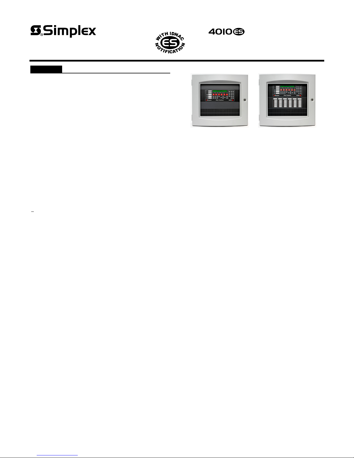
1-Bay Cabinet
1-Bay Cabinet with
LED Annunciation
4010ES Panel Type Reference
Optional block space modules include:
Fire Alarm Physical Bridge and Network Interface Cards
for Peer-to-Peer fire alarm network communications,
supports either Class B or Class X operation
Building Network Interface Module (BNIC), SafeLINC
Internet Interface, and BACpac Ethernet Portal
Dual Class A IDNAC Isolator (DCAI)
Dual RS-232 Module (for printer, PC annunciator or third
party interface)
VESDA Air Aspiration High Level Interface
Serial DACT
8 Zone IDC Modules Class A or B
4 Point Auxiliary Relay Module
Compatible with Simplex
®
remotely located:
4098-9757 QuickConnect2 and legacy 4098-9710
QuickConnect TrueAlarm smoke sensors
4003EC Small Voice Panels
4081 Series, 110 Ah Battery Chargers
4100-7400 Series Graphic Annunciators
4190 Series PC Annunciator, 4190 Series Fiber
Modems and Physical Bridges
4606-9102 Remote LCD Annunciator, 4100-9400
Series Remote InfoAlarm Command Centers, and 4602
Series Status Command Units (SCU) and Remote
Command Units (RCU) Annunciators
IP communicator compatibility
* See page 6 for additional listing information. This product has been approved by the
California State Fire Marshal (CSFM) pursuant to Section 13144.1 of the California Health
and Safety Code. See CSFM Listing 7165-0026:0369 for allowable values and/or
conditions concerning material presented in this document. NYC Fire Dept COA #6193.
Additional listings may be applicable; contact your local Simplex product supplier for the
latest status. Listings and approvals under Simplex Time Recorder Co. are the property of
Tyco Fire Protection Products.
Features
4010ES Agency listings:
UL 864, Fire Detection and Control (UOJZ), and
Smoke Control Service (UUKL), and Releasing
Service (SYZV)
UL 2017, Process Management Equipment (QVAX)
UL 1076, Proprietary Alarm Units-Burglar (APOU)
UL 1730, Smoke Detector Monitor (UULH)
ULC S527-99, Fire Detection and Control (UOJZC)
ULC S559-04, Supervising Station (DAYRC)
Introduction
4010ES Series Fire Detection and Control Panels
provide leading edge installation, operator, and service
features for customer applications in the mid-range
addressable fire alarm systems market. An on-board
Ethernet port provides fast external system
communications to expedite installation and service
activity. Dedicated compact flash memory archiving
provides secure on-site system information storage of
electronic job configuration files to meet NFPA 72
(National Fire Alarm and Signaling Code) requirements.
Modular design. A variety of functional modules are
available to meet specific system requirements. Selections
allow panels to be configured for either Stand-Alone or
Networked fire control operation.
Mechanical Description
Mounting box provides convenient stud markers for
drywall thickness and nail-hole knockouts for quicker
mounting
Smooth box surfaces are provided for locally cutting
conduit entrance holes exactly where required
The hinged User Interface panel easily opens for
internal access
Modules are power-limited (except as noted, such as
relay modules)
Doors include tempered glass inserts, boxes and doors
are available in platinum or red
Box and door/retainer assemblies are included with
Basic Panel assemblies
Cabinet assembly is rated NEMA 1 and IP 30
Cabinet assembly design has been seismic tested and
is certified to IBC and CBC standards as well as to
ASCE 7 categories A through F, requires battery
brackets as detailed on data sheet S2081-0019
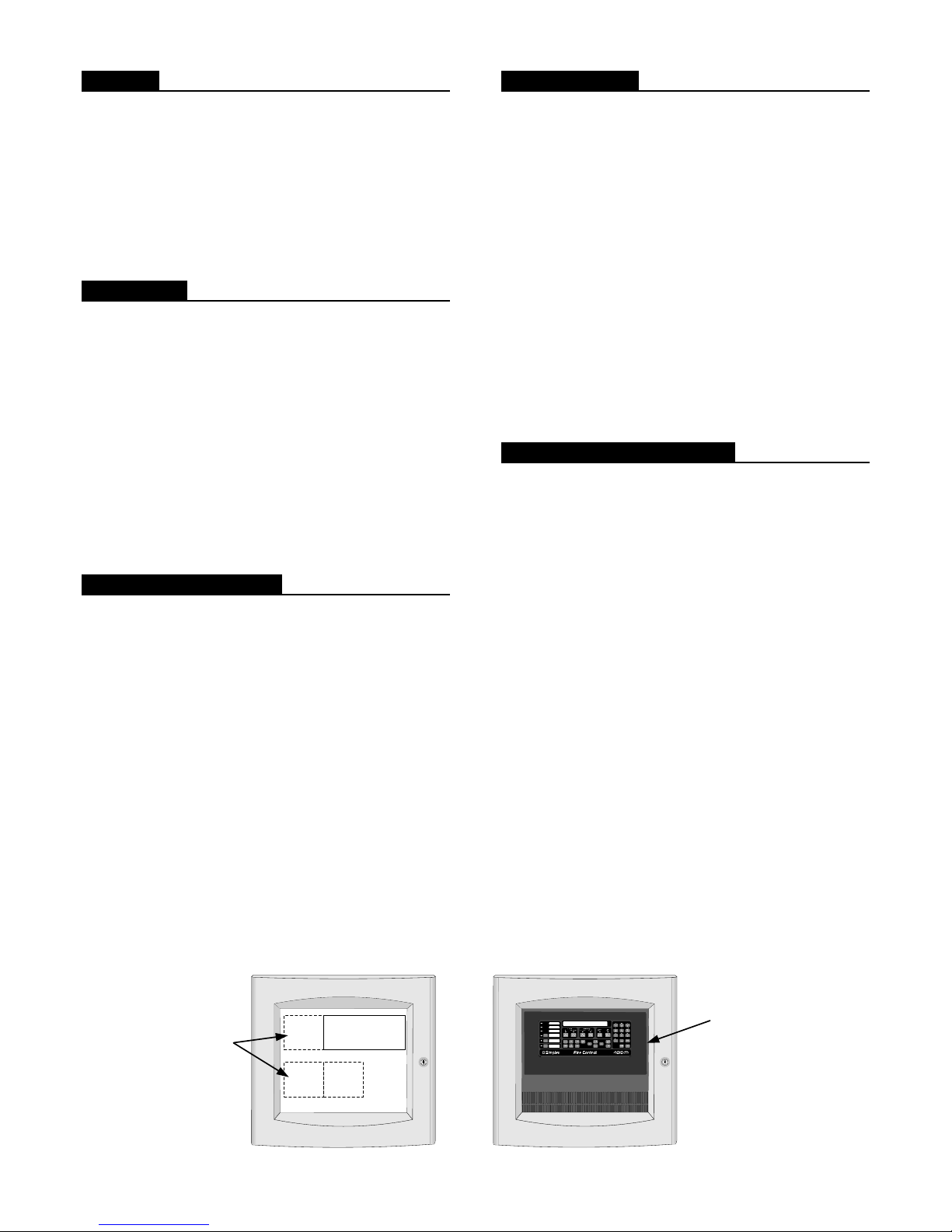
Panel Hardware
4010ES Block Space Option Cards mount to the left
of the 4010ES ESS. There are 3 available 4” x 5” blocks
for mounting 4010ES hardware options.
Other 4010ES Options: The 4010ES City Connect
module or the optional Alarm Relay module mount
directly to the ESS. These options are mutually exclusive.
Network Media modules mount directly to the 4010ES
Network Interface Card.
The TrueInsight Remote Gateway mounts on the back
side of the 4010ES User Interface Panel.
The Battery Compartment located in the bottom of
the 4010ES cabinet accepts two batteries, up to 33 Ah,
without interfering with expansion module space.
The illustrations at the bottom of this page identify
mounting locations available for optional 4010ES
modules. (refer to page 7 for additional information)
Software Feature Summary
TrueAlarm individual analog sensing with front panel
information and selection access
“Dirty” TrueAlarm sensor maintenance alerts, service
and status reports including “almost dirty”
TrueAlarm magnet test indication appears as distinct
“test abnormal” message on display when in test mode
TrueAlarm sensor peak value performance report
“Install Mode” allows grouping of multiple troubles
for uninstalled modules and devices into a single
trouble condition (typical with future phased
expansion); with future equipment and devices
grouped into a single trouble, operators can more
clearly identify events from the commissioned and
occupied areas
Module level ground fault searching assists
installation and service by locating and isolating
modules with grounded wiring
“Recurring Trouble Filtering” allows the panel to
recognize, process, and log recurring intermittent
troubles (such as external wiring ground faults), but
only sends a single outbound system trouble to avoid
nuisance communications
WALKTEST silent or audible system test performs an
automatic self-resetting test cycle
4" x 5"
3 available 4" x 5"
block spaces for
additional option cards
2 S4010-0011-5 11/2015
Block A
4" x 5"
Block B
Mounting Locations for Optional Modules, One-Bay Cabinet
Enhanced System
Supply
4" x 5"
Block D
TrueInsight Remote
Gateway mounts on
the back of the 4010ES
User Interface Panel
Operator Interface Features
Convenient and extensive operator information is
provided using a logical, menu-driven display
Multiple automatic and manual diagnostics for
maintenance reduction
Convenient PC programmer label editing
Password access control
Alarm and Trouble History Logs (up to 2000 total
events) are available for viewing from the LCD, or
capable of being printed to a connected printer, or
downloaded to a service computer
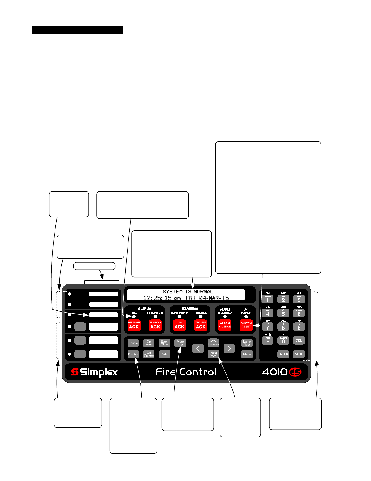
ULC SYSTEMS
require designating
a Ground Fault
indicator
3 PROGRAMMABLE LEDs
two selectable as Red or Yellow,
one selectable as Green or Yellow
Custom label insert
6 SYSTEM STATUS INDICATOR LEDs provide
system status indications, LEDs flash to indicate
a change in status and remain on-steady after
acknowledged until reset
2 X 40 LCD READOUT, LCD is
backlighted during normal conditions,
provides up to 40 characters for custom
label information
FIRST ALARM DISPLAY operation can
be selected for maintained display of first
alarm until acknowledged
Convenient Status Information. With the locking
door closed, the glass window allows viewing of the
display, status LEDs, and available operator switches.
Features include a two-line by 40-character, wide viewing
angle (super-twist) LCD with status LEDs and switches as
shown in the illustration below.
LED indicators describe the general category of activity
being displayed with the LCD providing more detail. For
the authorized user, unlocking the door provides access to
the control switches and allows further inquiry by
scrolling the display for additional detail.
The following illustration identifies the primary functions
of the operator interface.
FIRE ALARM ACK acknowledges a Fire Alarm
condition, logs the acknowledge, and silences the
operator panel and all annunciator tone-alerts
PRIORITY 2 ACK acknowledges a Priority 2 Alarm
condition, logs the acknowledge, and silences the
operator panel and all annunciator tone-alerts
SUPV ACK acknowledges system supervisory
conditions, logs the acknowledge, and silences the
operator panel and all annunciator tone-alerts
TROUBLE ACK acknowledges system trouble
conditions, logs the acknowledge, and silences the
operator panel and all annunciator tone-alerts
ALARM SILENCE causes audible notification
appliances to be silenced (depending on panel
programming) typically after evacuation is complete and
while alarm source is being investigated; may allow
visible notification to continue (strobes still flashing)
SYSTEM RESET restores control panel to normal when
all alarmed inputs are returned to normal
Waterflow-East
Waterflow-West
Ground Fault
City Disconnect
Elevator Bypass
Ground Fault
Latch
3 PROGRAMMABLE
FUNCTION SWITCHES
with yellow LED
indicators
3 S4010-0011-5 11/2015
POINT STATUS
CONTROL KEYS:
Point Enable and
Disable
Force On or Arm
Force Off or Disarm
Return On/Off or
Arm/Disarm to Auto
Mode
ADDITIONAL FUNCTION
KEYS:
Event Time Request
More Information Request
Lamp Test
LCD NAVIGATION
CONTROL:
Menu selection
Vertical and
Horizontal position
selection buttons
NUMERIC KEYPAD for
point category and point
selection (alphabet
characters are not used at
this time)
 Loading...