

Page 1

4010ES
Fire Alarm System
Installation
Guide
579-989
Rev. M
Page 2

Page 3
Copyrights, Trademarks, Cautions, Warnings and Regulatory Info
Copyrights and Trademarks
Cautions, Warnings and Regulatory Information
©2011 - 2016 Tyco Fire Protection Products. All rights reserved.
Specifications and other information shown were current as of publication and are subject to
change without notice. TYCO, SIMPLEX, and the product names listed in this material are
marks and/or registered marks. Unauthorized use is strictly prohibited.
READ AND SAVE THESE INSTRUCTIONS- Follow the instructions in this installation
manual. These instructions must be followed to avoid damage to this product and asso ciated
equipment. Product operation and reliability depend upon proper installation.
DO NOT INST ALL ANY SIMPLEX® PRODUCT THAT APPEARS DAMAGED- Upon
unpacking your Simplex product, inspect the contents of the carton for shipping damage. If
damage is apparent, immediately file a claim with the carrier and notify an authorized Simplex
product supplier.
ELECTRICAL HAZARD - Disconnect electrical field power when making any internal adjust-
ments or repairs. All repairs should be performed by a representative or authorized agent of
your local Simplex product supplier.
ST ATIC HAZARD - Static electricity can damage components. Handle as follows:
• Ground yourself before opening or installing components.
• Prior to installation, keep components wrapped in anti-static material at all times.
EYE SAFETY HAZARD - Under certain fiber optic application conditions, the optical output of
this device may exceed eye safety limits. Do not use magnification (such as a microscope or
other focusing equipment) when viewing the output of this device.
FCC RULES AND REGULATIONS – PART 15 - This equipment has been tested and found to
comply with the limits for a Class A digital device pursuant to Part 15 of the FCC Rules. These
limits are designed to provide reasonable protection against harmful interference when the
equipment is operated in a commercial environment. This equipment generates, uses, and can
radiate radio frequency energy and, if not installed and used in accordance with the instruction
manual, may cause harmful interference to radio communications. Operation of this equipment
in a residential area is likely to cause harmful interference in which case the user will be
required to correct the interference at his own expense.
SYSTEM REACCEPT ANCE TEST AFTER SOFTWARE CHANGES - T o ensure proper system
operation, this product must be tested in accordance with NFPA 72® after any programming
operation or change in site-specific software. Re-acceptance testing is required after any
change, addition or deletion of system components, or after any modification, repair or
adjustment to system hardware or wiring.
All components, circuits, system operations, or software functions, known to be affected by a
change must be 100% tested. In addition, to ensure that other operations are not inadvertently
affected, at least 10% of initiating devices that are not directly affected by the change, up to a
maximum of 50 devices, must also be tested and proper system operation verified.
NFPA 72® is a registered trademark of the National Fire Protection Association.
iii
Page 4

Page 5

Table of Contents
Copyrights, Trademarks, Cautions, Warnings and Regulatory Info............................. iii
Copyrights and Trademarks ................................................................................................... iii
Cautions, Warnings and Regulatory Information ...................................................................iii
Chapter 1 Overview ...........................................................................................1-1
Introduction ..........................................................................................................................1-1
In this chapter ............... .. ............................................. ... ............................................. ........1-1
Standalone configuration ...............................................................................................1-2
Overview ..............................................................................................................................1-2
Standalone system layout ....................................................................................................1-2
Network configuration .....................................................................................................1-3
Overview ..............................................................................................................................1-3
Connecting network loops ....................................................................................................1-4
Network communication .......................................................................................................1-4
Chapter 2 Basic Hardware ................................................................................ 2-1
Introduction ..........................................................................................................................2-1
In this chapter ................................................... ... ............................................. .. .................2-1
CPU ...................................................................................................................................2-2
Overview ..............................................................................................................................2-2
CPU LEDs ............................................................................................................................2-3
CPU jumper settings ............................................................................................................2-5
CPU switches .......................................................................................................................2-6
CPU connectors/ports/terminal block ...................................................................................2-6
CPU card specifications .......................................................................................................2-7
Operator interface ...........................................................................................................2-8
Overview ..............................................................................................................................2-8
Main system supply (MSS) .............................................................................................2-9
Overview ..............................................................................................................................2-9
MSS LEDs and jumpers .....................................................................................................2-11
MSS specifications .............................................................................................................2-12
48-LED Module ...............................................................................................................2-14
Overview ............................................................................................................................2-14
48-LED Module specifications ...........................................................................................2-15
System power ...................................... ... ... .... ... ... ... .... ... ... ... .... ... ... ................................2-16
Main system power ............................................................................................................2-16
Backup batteries ................................................................................................................2-16
Chapter 3 Panel configurations ........................................................................3-1
Introduction ..........................................................................................................................3-1
In this chapter ................................................... ... ............................................. .. .................3-1
One-bay 4010ES Panels ..................................................................................................3-2
Overview ..............................................................................................................................3-2
Optional modules .............................................. ... ................................................................3-4
Back box mechanical specifications ....................................................................................3-5
Two-bay 4010ES Panels ............ .... ... ... ... ... .......................................... .... ... ... ..................3-6
Overview ..............................................................................................................................3-6
Optional modules .............................................. ... ................................................................3-9
Back box mechanical specifications ....................................................................................3-9
v
Page 6

Table of Contents
Chapter 4 Orderable panels and devices ........................................................ 4-1
Introduction ..........................................................................................................................4-1
In this chapter ................................................... ... ............................................. .. .................4-1
Panels ...............................................................................................................................4-2
One-bay 4010ES Panels .....................................................................................................4-2
Two-bay 4010ES Panels .....................................................................................................4-2
Optional modules ... ... ... .... ... ... ... .... ... ... ............................................................................4-3
Local optional modules ..................................... ... ............................................... ... ..............4-3
Remote devices ...................................................................................................................4-4
Adjunct features ...................................................................................................................4-5
End user programming tools ................................................................................................4-5
LED kits for the 48-LED Module ..........................................................................................4-5
Chapter 5 Installing 4010ES systems ..............................................................5-1
Introduction ..........................................................................................................................5-1
In this chapter ................................................... ... ............................................. .. .................5-1
Mounting the panel ..........................................................................................................5-2
Installing the back box .........................................................................................................5-2
Attaching the dead front .......................................................................................................5-3
Attaching doors ....................................................................................................................5-4
General field wiring guidelines ......................................................................................5-5
Power-limited guidelines ......................................................................................................5-5
Connecting 4010ES basic components .........................................................................5-7
Connecting the CPU and the operator interface ..................................................................5-7
Connecting the MSS ............................................................................................................5-9
Connecting the 48-LED Module .........................................................................................5-10
RUI wiring .......................................................................................................................5-11
Overview ............................................................................................................................5-11
Installing the optional modules .............................................. ................................ ......5-13
Overview ............................................................................................................................5-13
Installing one-block and two-block cards ...........................................................................5-13
Address configuration DIP switch ...............................................................................5-14
Overview ............................................................................................................................5-14
Connecting main system power ...................................................................................5-16
Overview ............................................................................................................................5-16
Panel power-up sequence .................................................................................................5-16
Chapter 6 MSS field wiring ...............................................................................6-1
Introduction ..........................................................................................................................6-1
In this chapter ................................................... ... ............................................. .. .................6-1
Power supply wiring distances ......................................................................................6-2
Overview ..............................................................................................................................6-2
Class A NAC wiring table ..................................... ... .. ................................................ ... ... .....6-2
Class B NAC wiring table ..................................... ... .. ................................................ ... ... .....6-3
MSS NAC field wiring guidelines ...................................................................................6-4
Guidelines ............................................................................................................................6-4
MSS NAC wiring ..............................................................................................................6-5
Class A NAC Wiring ................................................................... ..........................................6-5
Class B NAC wiring ........................................................................................... .. .................6-6
vi
Page 7

Table of Contents
MSS IDNet wiring .............................................................................................................6-7
Overview ..............................................................................................................................6-7
Wiring parameters ................................................................................................................6-7
Class A wiring ......................................................................................................................6-8
Class B wiring ......................................................................................................................6-9
MSS auxiliary power wiring ..........................................................................................6-10
Guidelines ..........................................................................................................................6-10
Wiring .................................................................................................................................6-11
MSS auxiliary relay wiring ............................................................................................6-12
Guidelines ..........................................................................................................................6-12
Wiring .................................................................................................................................6-12
Chapter 7 PC software connections ................................................................7-1
Introduction ..........................................................................................................................7-1
In this chapter ................................................... ... ............................................. .. .................7-1
Software modes ................ ... ... ... .... ... ... ....................................... ... ... ... .... ... ... ... .... ...........7-2
Software modes ...................................................................................................................7-2
Ethernet service port ........... ... ... .... ... ... ... ... ......................................................................7-4
Ethernet service port overview .............................................................................................7-4
Chapter 8 System wiring checkout and earth fault diagnostics ...................8-1
Introduction ..........................................................................................................................8-1
In this chapter ................................................... ... ............................................. .. .................8-1
Checking system wiring .................................................................................................8-2
Overview ..............................................................................................................................8-2
Using the multimeter ............................................................................................................8-2
Meter readings .................................................. ............................................. ... .. .................8-3
Earth fault diagnostics ....................................................................................................8-4
Overview ..............................................................................................................................8-4
General guidelines .................................................. .. ...........................................................8-4
Earth fault searching from the front panel ....................................................................8-6
Overview ..............................................................................................................................8-6
Access level selection ..........................................................................................................8-6
Starting the Earth Fault Search ............................................................................................8-6
Search Option A: Select Location ........................................................................................8-7
Search Option B: Select Location ........................................................................................8-7
Search Option C: Last Search Result ..................................................................................8-8
Completing the search .........................................................................................................8-8
Earth fault search results ...............................................................................................8-9
Overview ..............................................................................................................................8-9
Non-point faults ....................................................................................................................8-9
Point Faults ..........................................................................................................................8-9
Fault Not Found ............................................................................ ... ... ...............................8-10
No Fault .............................................................................................................................8-10
Result Not Available ...........................................................................................................8-10
Chapter A ULC programming requirements ...................................................A-1
Introduction .........................................................................................................................A-1
In this chapter ................................................... ... ............................................. .. ................A-1
vii
Page 8

Table of Contents
Common earth fault ground indicator .......................................................................... A-2
Overview .............................................................................................................................A-2
Step 1. Open CPU card properties dialog ...........................................................................A-2
Step 2. Program the LED .................................................................................................... A-3
Simultaneous alarm display .......................................................................................... A-4
Overview .............................................................................................................................A-4
Creating annunciation zone lists .............................................................. ... ........................A-4
Programming the address and mode for each LED ............................................................A-5
Setting alarm verification timer to Canadian operation .............................................. A-7
Introduction .........................................................................................................................A-7
Procedure ...........................................................................................................................A-7
Setting Alarm Reset/Inhibit Timer ................................................................................. A-8
Overview .............................................................................................................................A-8
Enabling Alarm Reset/Inhibit Timer .................................................................................... A-8
Alarm Cutout Timer ........................................................................................................ A-9
Overview .............................................................................................................................A-9
Enabling Alarm Cutout Timer .............................................................................................. A-9
Chapter B UL programming requirements ......................................................B-1
Introduction .........................................................................................................................B-1
In this chapter ................................................... ... ............................................. .. ................B-1
Setting Alarm Verification to US operation .................................................................. B-2
Overview .............................................................................................................................B-2
Procedure ...........................................................................................................................B-2
Alarm Cutout Timer ........................................................................................................ B-3
Overview .............................................................................................................................B-3
Enabling Alarm Cutout Timer .............................................................................................. B-3
Non Steady Visual Evacuation system option ............................................................. B-4
Overview .............................................................................................................................B-4
Chapter C Simplex special application NAC-compatible notification appliances and
accessories ........................................................................................................C-1
Chapter D Cooper Wheelock appliances compatible with 4010ES Wheelock protocol
for special applications .....................................................................................D-1
Overview .............................................................................................................................D-1
Synchronizing horn strobes ................................................................................................ D-1
Synchronizing strobes .........................................................................................................D-2
Appliances with synchronizing strobes ...............................................................................D-3
Synchronizing horns ...........................................................................................................D-4
Coded audible appliances ...................................................................................................D-5
Non-synchronizing appliances ............................................................................................D-5
viii
Page 9

Chapter 1
Overview
Introduction The 4100ES FACP panel is an expandable fire alarm panel, which can be used as a standalone
system, or can be networked with the following panels to create a larger network:
• 4002
• 4010
• 4020
• 4100
• 4100U
• 4100ES
• 4010ES
• 4007ES
• 4190 TrueSite Workstation
• 4190 TrueSite Incident Commander
• 4190 Network System Integrator
The 4100ES comes with basic system components pre-installed. This chapter provides an
overview of standalone and network 4010ES panel concepts:
Standalone. Comprised of on e 4010ES FACP and its assorted notification appliances,
initiating devices, and signaling line circuit devices.
Network. Multi-FACP systems connected by 4120 network cards. Each panel maintains the
status and control of its own circuit points, while monitoring and controlling activity at other
locations. Network nodes may perform similar tasks, or may be dedicated to specific
functions.
In this chapter This chapter covers the following topics:
Topic Page
Standalone configuration 1-2
Network configuration 1-3
1-1
Page 10
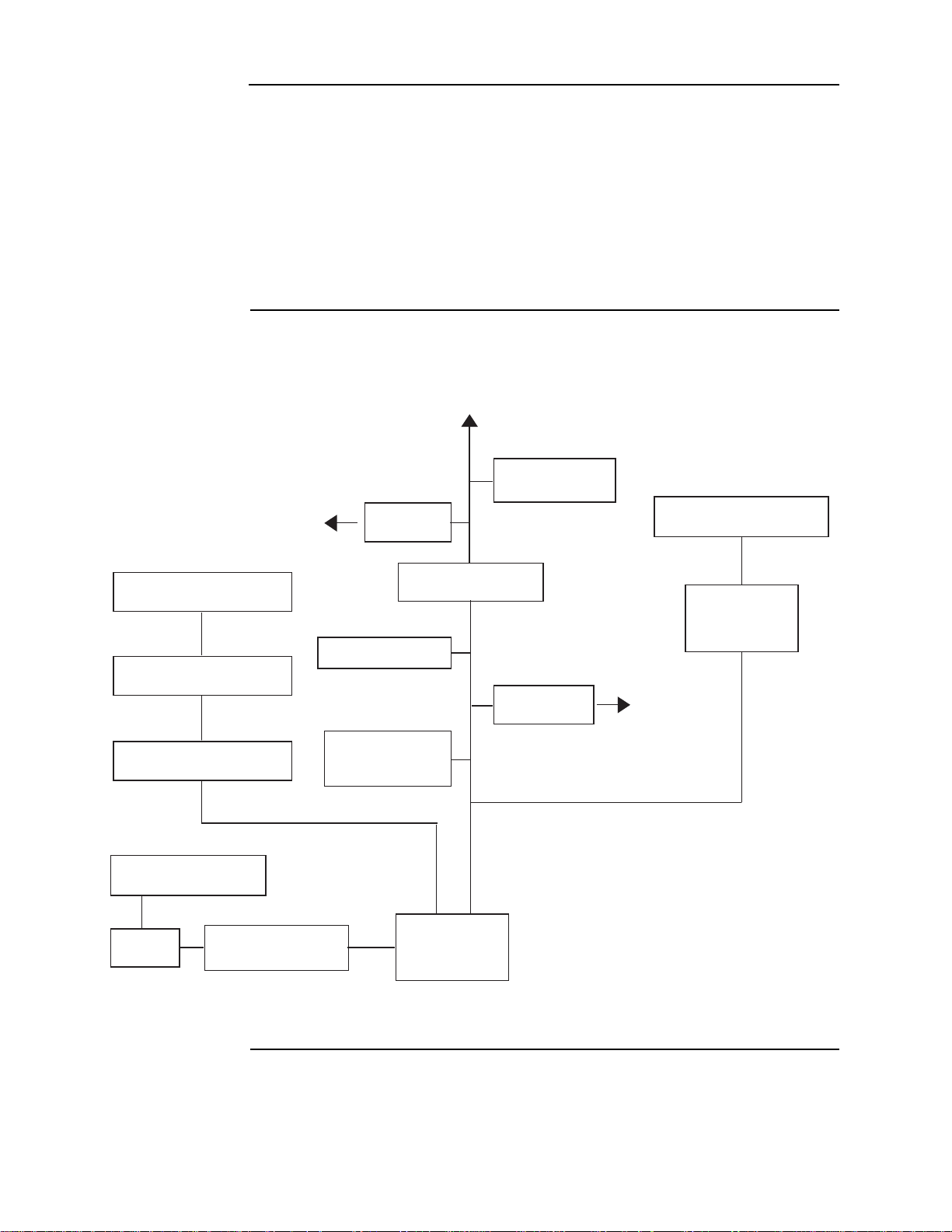
Standalone configuration
4010ES Panel
Remote Annunciation
(Graphical or LCD)
TrueAlert Non-Addressable
Devices
TrueAlarm Thermal
Sensor with Base
Monitor and
Control ZAMs
Addressable Station
Remote Line Powered
Isolator
Supervised
IAM
TrueAlarm Smoke
Sensor with Base
To additional IDNet devices
4009A Series
Devices
TrueAlert Non-Addressable
Devices
to Device(s)
to Device(s)
RUI
TrueAlert Non-Addressable
Devices
TrueAlert Non-Addressable
Devices
4010ES NAC
IDnet
Note: Some 4009-series
devices are controlled
through RUI and not
IDNet
4009T or
4009TPS
TrueAlert Addressable
Devices
Overview The standalone version of the 4010ES is used for smaller, or single-building applications. A
standalone system is ideally placed into a small building that requires a limited number of
notification appliances and initiating devices.
If a small building is being expanded, or if other buildings are being constructed in the same
general area, as in a campus application, the standalone 4010ES can be upgraded to a network
system and linked with other 4010, 4100, 4100U, 4100ES and 4010ES panels to create a larger
network.
Note: You must order and install the 4010-9902 and the 4010-9922 network cards into the standalone
system to enable network functionality.
Standalone system layout
Figure 1-1 below shows the layout of the 4010ES standalone configuration.
Figure 1-1. Standalone 4010ES system
1-2
Page 11
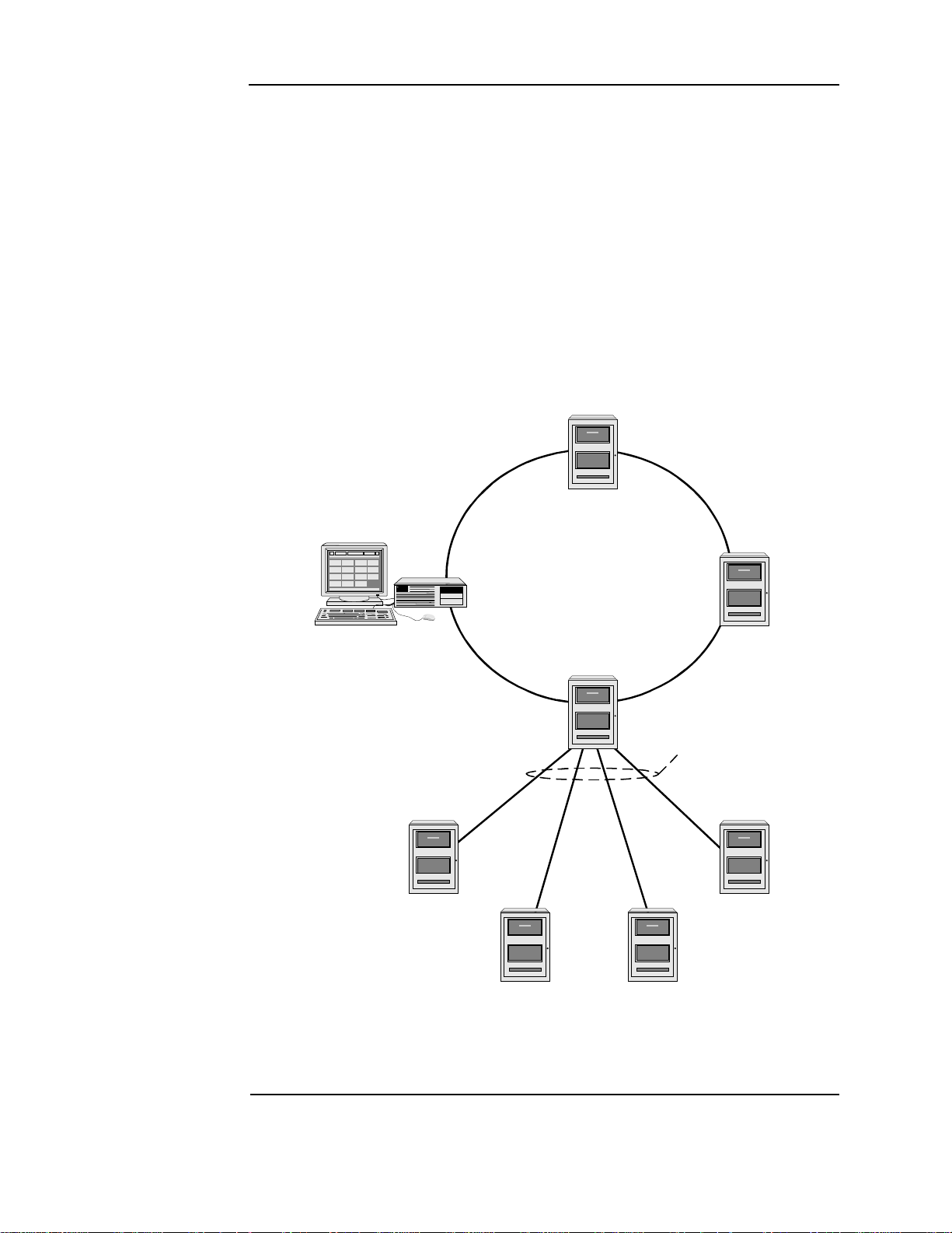
Network configuration
Ring Topology
Physical Bridge Links
(Star Topology)
TSW
Network Display Unit
(NDU)
Hub Node
Distributed Remote
Node Locations
Note: Physical Bridge
links in a 4010ES
requires a two-bay box
Overview The 4010ES can be expanded to a network system by using the 4010-9902 and the 4010-9922
network interface cards (NICs). When a NIC is installed into a 4010ES host panel, it is used to
connect to up to 98 other network nodes. Nodes may consist of other host 4010ES panels, or
they may be completely different: 4010ES FACPs and TrueSite Workstation (TSW) are
examples of what could be used as nodes. A node is a self-sufficient FACP that controls
appliances and devices, which also has the capability of controlling and communicating with
other nodes.
The network configuration supports two prevalent architectures or wiring configurations: hub
(or ring), or star. A networked system can also use a combination of the two.
The hub configuration consists of a main loop with nodes connected in a radial manner. The
star configuration consists of several nodes connected directly to one common node. Physical
bridge cards are used for the star configuration. Physical bridges reduce the amount of wire that
would otherwise be needed to connect all nodes in a loop. A combination of the two styles is
illustrated in Figure 1-2.
Figure 1-2. Hub/ring configuration
1-3
Page 12
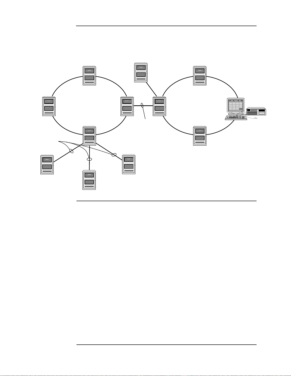
Network configuration, continued
Remote Loop
Physical Bridge Link
Local Loop
Physical Bridging
(Star Configuration - 3 max)
TSW
Physical
Bridge
Link
Physical Bridge Links
Hub Node
Hub
Node
Remote
Node
Connecting network loops
Network loops can be joined by using physical bridge cards. There may be no more than two
Style 7 network loops, two hub configurations, connected in tandem. For every two loops that
are interconnected using one physical bridge, there can be a maximum of three physical
bridges used in a star configuration. See Figure 1-3.
Network communication
Network communication is achieved using the 4010-9902 and the 4010-9922 NICs. Each
network node requires a NIC. Once the FACP is a network node, it may be programmed to be
fully in control of other nodes, to be fully passive, or anywhere in between.
The 4010-9902 and the 4010-9922 NICs are option cards that use a PDI connector to
communicate with the CPU. The NICs allow for communication between each panel using a
fiber or twisted shielded pair wire in a Style 4 or Style 7 wiring configuration.
The NICs are designed to be connected in a point-to-point arrangement, so that one wire fault
does not cause the entire system to fail. The point-to-point arrangement provides the most
secure and fault-tolerant wiring possible.
Two types of media cards can be used with the NICs:
• The Fiber-Optic Media (4010-9819) card can be used for electrically noisy environments,
• The Wired Media Card (4010-9818) is used in all other types of applications.
Up to two media cards can be plugged into each NIC. The same NIC can use a combination of
different types of media boards; for example, a NIC may have a Wired Media card connected
to the left port, a Fiber-Optic Media card connected to the right port.
For setup and installation of a physical bridge card, refer to document 579-184: 4100/4120/
4010-Series Physical Bridges and Media Modules.
Figure 1-3. Interconnected loop configuration
or for connecting externally to other buildings.
For setup and installation of network interface cards, refer to document 579-956: 4010ES
Network Interface and Media Card Installation Instructions.
1-4
Page 13

Chapter 2
Basic Hardware
Introduction The 4010ES FACPs are one-bay or two-bay back boxes with a dead front and glass door,
containing a set of pre-installed basic system components:
• Dead front-mounted CPU (2x40 character LCD or InfoAlarm)
• Operator interface
• Main system supply (MSS) (notification appliance circuits and system power)
• 48-LED Module (for some 4010ES configurations)
• IDNet+ or MX Loop circuit (for initiating and other devices)
• PDI Blocks for optional modules
In addition to the basic modules, optional modules can be installed inside the one-bay or two-
bay 4010ES panels. The types of modules available depend on the panel configuration, as well
as the accessibility, and availability, of the power distribution interface (PDI) blocks. The
number of available PDI blocks depends on the system ordered. See Chapter 3, “Panel
Configurations.”
In this chapter This chapter covers the following topics:
Topic Page
CPU 2-2
Operator interface 2-8
Main system supply (MSS) 2-9
48-LED Module 2-14
System power 2-16
2-1
Page 14
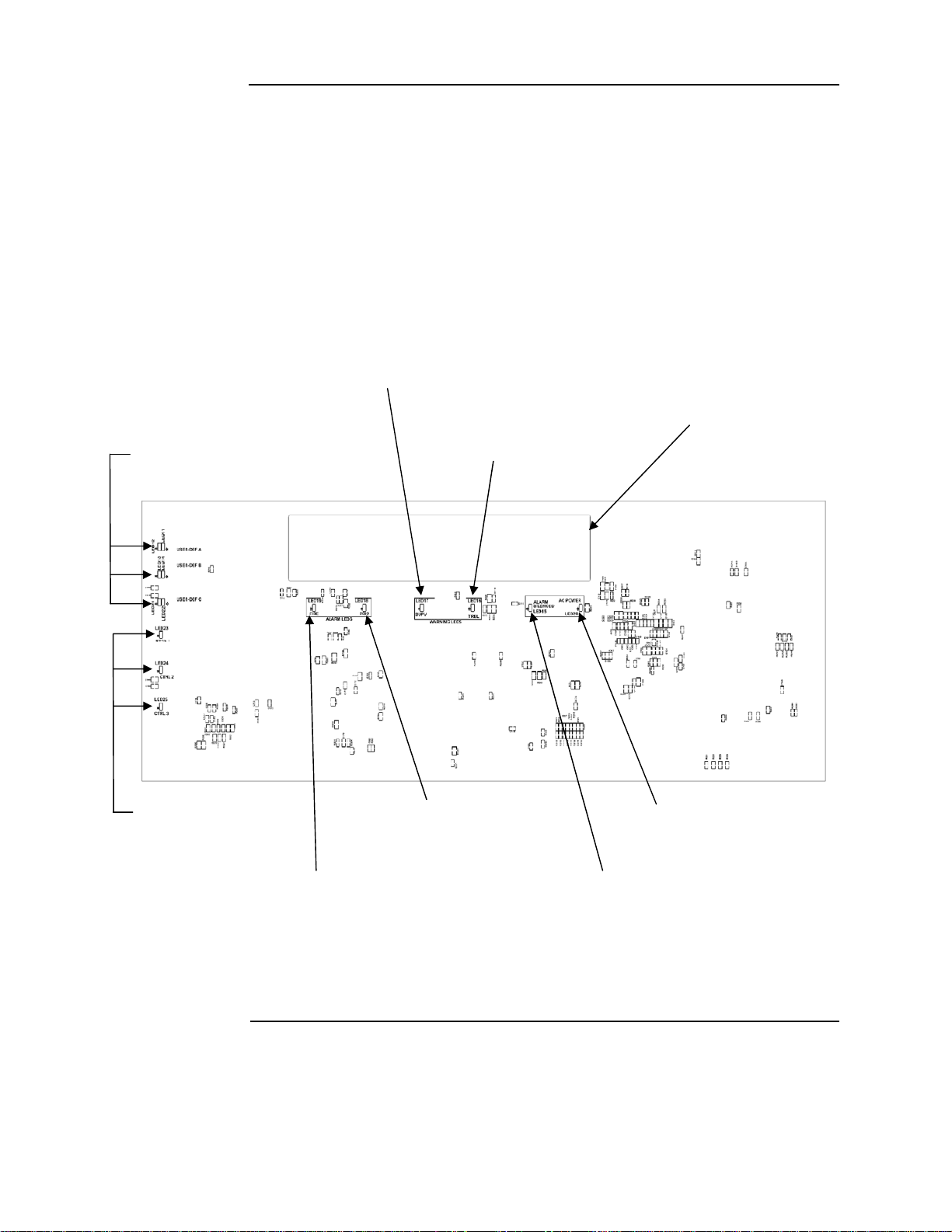
CPU
SUPERVISORY LED (LED17)
2x40 LCD
USER-DEFINABLE LEDs TROUBLE LED (LED16)
(LED11-LED14, LED21, LED22)
CONTROL KEY LEDs PRIORITY 2 ALARM LED AC POWER LED (LED20)
(LED23-LED25)
(LED18)
FIRE ALARM LED (LED19) ALARM SILENCED LED (LED15)
Note: All LEDs on the front side of the board are used for standard fire
alarm functions and are visible through the dead front membrane.
Overview The CPU card (Figure 2-1 and Figure 2-2) is the main decision maker in the 4010ES FACP. It
holds all job information, current system status, and communicates to all slaves connected to
the 4010ES panel. A 4010ES CPU contains the following features:
• 2 x 40 LCD display and piezo (non-InfoAlarm systems only) - Annunciation for
supervisory , trouble, priority 2 and fire alarm signals.
• Compact flash socket (card pre-installed) - Alternate exec and job storage.
• Ethernet service port - PC connection used by Simplex service personnel.
• Serial service port - Interface for service equipment or Simplex service personnel.
• Style 4/7 Remote Unit Interface - Remote connection to system components not located
within 4010ES box.
Figure 2-1. Dead front-mounted CPU with a 2 x 40 display (front view)
Continued on next page
2-2
Page 15
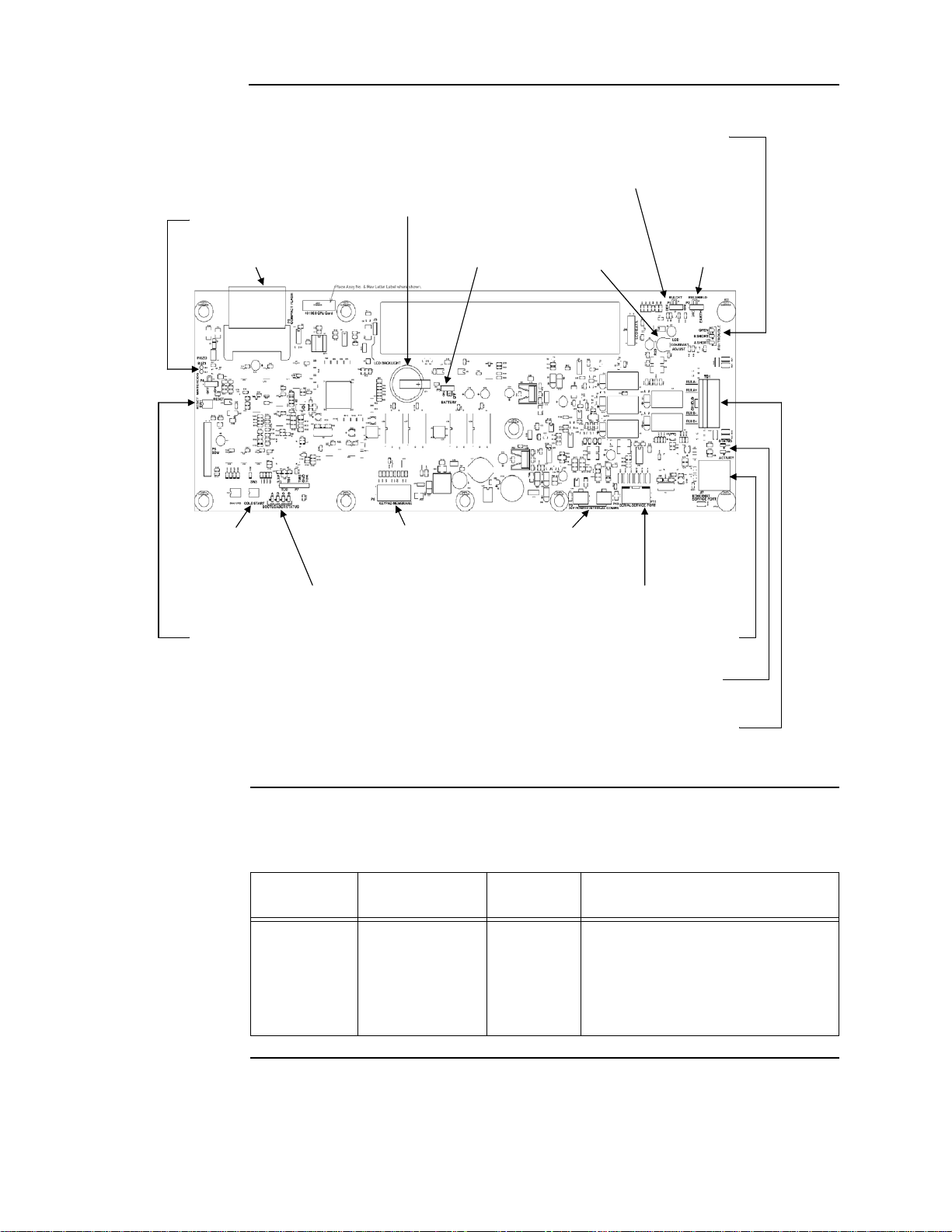
CPU, continued
RUI TROUBLE LEDs (LED1-LED3)
RUI ENABLE JUMPER (P1)
BATTERY (BT1)
PIEZO CONNECTION (BUZ1)
BATTERY ENABLE LCD CONTRAST RUI SHIELD
COMPACT FLASH (P3) JUMPER (P5) ADJUST (R23) JUMPER (P2)
COLD START KEYPAD MEMBRANE 24V POWER/COMMS
SWITCH (SW3) CONNECTOR (P8) CONNECTORS (P9 & P10)
BOOTLOADER STATUS LEDs (LED7-LED10) SERIAL SERVICE PORT (P11)
RESET SWITCH (SW1) ETHERNET SERVICE PORT (J7)
ETHERNET STATUS LED (LED5) & ACTIVITY LED (LED6)
RUI PLUGGABLE TERMINAL BLOCK (TB1)
Overview
Figure 2-2. Dead front-mounted CPU with a 2 x 40 display (back view)
CPU LEDs The tables below outline the functions of the LEDs on the CPU card.
Table 2-1. Reset LED
Reference
designator
LED4 RESET Yellow
Silkscreen name Color Status
ON = CPU is in reset
FLASHING = Board is unable to come
out of reset. Possibly corrupt CFIG, or
board needs to be replaced.
OFF = CPU is running normally
2-3
Continued on next page
Page 16

CPU, continued
CPU LEDs
T able 2-2. Ethernet LEDs
Reference
designator
LED5 STATUS Green ON = Cable connected
LED6 ACTIVITY Red FLASHING = Ethernet activity
Reference
designator
LED1 OPEN Yellow ON = Class A fault (open-circuit) or a short
LED2 B SHORT Yellow ON = Short-circuit on the primary side
LED3 A SHORT Yellow ON = Short-circuit on the secondary side
Reference
designator
LED11
LED12 Yellow ON = User-definable key A active (Note)
LED13
LED14 Red ON = User-definable key B active (Note)
Silkscreen name Color Status
Table 2-3. RUI trouble LEDs
Silkscreen name Color Status
Table 2-4. Front panel LEDs
Silkscreen name Color Status
Red ON = User-definable key A active (Note)
USER-DEF A
Yellow ON = User-definable key B active (Note)
USER-DEF B
LED15
LED16 TRBL Y ellow ON = Trouble
LED17 SUPV Yellow ON = Supervisory
LED18 PRI2 Red ON = Priority 2 alarm
LED19 FIRE Red ON = Alarm
LED20 AC POWER Green
LED21
LED22 Green ON = User-definable key C active (Note )
LED23 CTRL 1 Yellow ON = Control key 1 active
LED24 CTRL 2 Yellow ON = Control key 2 active
LED25 CTRL 3 Yellow ON = Control key 3 active
Note: Only one LED in each user-definable pair will be on at a time, never both.
ALARM
SILENCED
USER-DEF C
Yellow ON = Alarm silenced
ON = System power is functioning
properly
Yellow ON = User-definable key C active (Note)
Continued on next page
2-4
Page 17

CPU, Continued
CPU LEDs
Table 2-5. Bootloader status LEDs
Status
Reference
designator
Silkscreen
Name
LED7 LED8 LED9 LED10
AB C D
Color Green Green Green Green
Bootloader
Initialization
Bad Master
CRC or No
Master
Present
Diagnostic
Fail - RAM
Diagnostic
Fail -
Bootloader
CRC
Downloading
Master
Downloading
CFIG
Downloading
MsgLib
On (0.25 s)
Off (0.25 s)
Off Off Off On
On Off Off On
Off On Off On
On On Off On
Off Off On On
On Off On On
On (0.25 s)
Off (0.25 s)
On (0.25 s)
Off (0.25 s)
On (0.25 s)
Off (0.25 s)
CPU jumper settings
Downloading
Bootloader
Download
Successful
Off On On On
On On On On
T able 2-6. CPU settings
Reference designator Silkscreen name Position Function
1-2 Enable RAM battery backup
P5 BATTERY
2-3 (default) Disable RAM battery backup
1-2 (default) Disable RUI
P1 RUI CKT
2-3 Enable RUI
1-2 (default) RUI shield tied to 24C (Note)
P2 RUI SHIELD
2-3 RUI shield tied to earth
Note: Some devices that connect to RUI have inherently grounded shield terminals, in which case, 24C
cannot be used. If 24C is used, a negative earth fault will occur.
2-5
Page 18

CPU, continued
CPU switches
Table 2-7. Switches
CPU connectors/ ports/terminal block
Reference
designator
SW1 RESET
SW3 COLD START
Reference
designator
P3 COMPACT FLASH
Silkscreen name Function
Silkscreen name Function
Short press (< 3 seconds) to activate a software-controlled
reset (warm start).
Press and hold (> 3 seconds) to force a hardware reset
(also a warm start).
Generally, unless the CPU card appears to be locked up,
you should always use the software-controlled reset.
A warm start preserves the logs and the disabled status of
any points that are in the disabled state.
During startup, press and hold this button to clear all history
logs and enable any points that were previously disabled.
Table 2-8. Connectors/po rts/terminal bl ock
Used for alternative job/exec storage. Card does not
“run” out of compact flash.
P8
P9 & P10
P11
J7
TB1
KEYPAD
MEMBRANE
24 V POWER/
INTERNAL COMMS
SERIAL SERVICE
PORT
Ethernet SERVICE
PORT
RUI A-, RUI A+,
SHIELD, RUI B-, RUI
B+
Used to communicate user inputs from the keypad
membrane to the CPU card.
Used to provide the necessary connections to daisy
chain 4100 comms and 24 VDC card power in an in-out
fashion. 24 VDC card power originates from the MSS.
4100 comms originates from the CPU card.
Used to connect the CPU card to the remote service
gateway. It may also be used as a service port if the
Ethernet service port is not available.
Used to connect the panel to a local PC through the front
panel Ethernet connection board, or 4010-9914 BNIC.
Remote user interface (RUI) used for communication
between the CPU and remote slaves.
2-6
Page 19

CPU, continued
CPU card specifications
Table 2-9 shows the battery current draw for the CPU card.
Table 2-9. Battery standby (24 V)
Configuration Supervisory current draw Alarm current draw
RUI disabled 124 mA 173 mA
RUI enabled - no load 149 mA 198 mA
RUI enabled - full load 176 mA 225 mA
T able 2-10 shows the maximum draw over the voltage range.
Table 2-10. Maximum draw over voltage range
Configuration Supervisory current draw Alarm current draw
RUI disabled 144 mA 208 mA
RUI enabled - no load 167 mA 226 mA
RUI enabled - full load 186 mA 248 mA
Note: CPU InfoAlarm supervisory and alarm current draws are both the same as the supervisory current
draw.
2-7
Page 20
Operator interface
A B C D E F G H I
J K L M N O P Q R
'S P' ( ) , # :
S T U V W X Y Z /
ZONE
1
SIG2AUX
3
FB4IO5IDNet
6
P7A8L
9
NET ADDR
0
C/Exit
Menu Enter
Prev ious
Next
Page Dn
Page Up
AC
Power
ALARMS
Fire
Alarm
Prior ity 2
Alarm
WARNINGS
System
Supervi sory
System
Trouble
Alarm
Silenced
Fir e A l ar m
Ack
Prior ity 2
Ack
Supv
Ack
Trouble
Ack
Alarm
Silence
System
Reset
Ground Fault
Water flow-We st
Waterflow-East
Cit y Disconnect
Manual E vac
Door Hold er
Bypass
Drill
Language
Toggle
Smoke Sensor
Almost Dirty Ch eck
Lamp Test
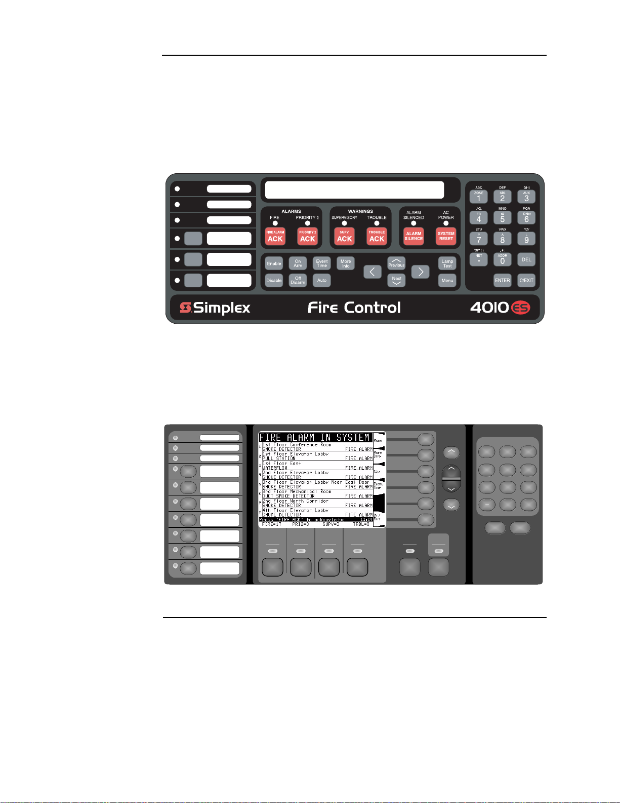
Overview The two operator interfaces which are available with the 4010ES are shown below.
The operator interface is used to obtain fire alarm, priority 2, supervisory, trouble, and other
statuses through the display and LEDs. Control functions are accessed using dedicated and
user-programmable keys.
Figure 2-3 is the standard 2 x 40 LCD operator interface. This model includes a 2 line by 40
character liquid crystal display. The membrane is available in both English and French.
Figure 2-3. Stan da rd op era t or interfa ce
Figure 2-4 is the InfoAlarm operator interface. This model includes a larger graphical display,
which can display more information simultaneously.
Note: The InfoAlarm operator interface can only be installed on two-bay 4010ES panels. See Chapter 3,
“Panel Configurations,” for details on two-bay panels.
Figure 2-4. InfoAlarm operator interface
2-8
Page 21
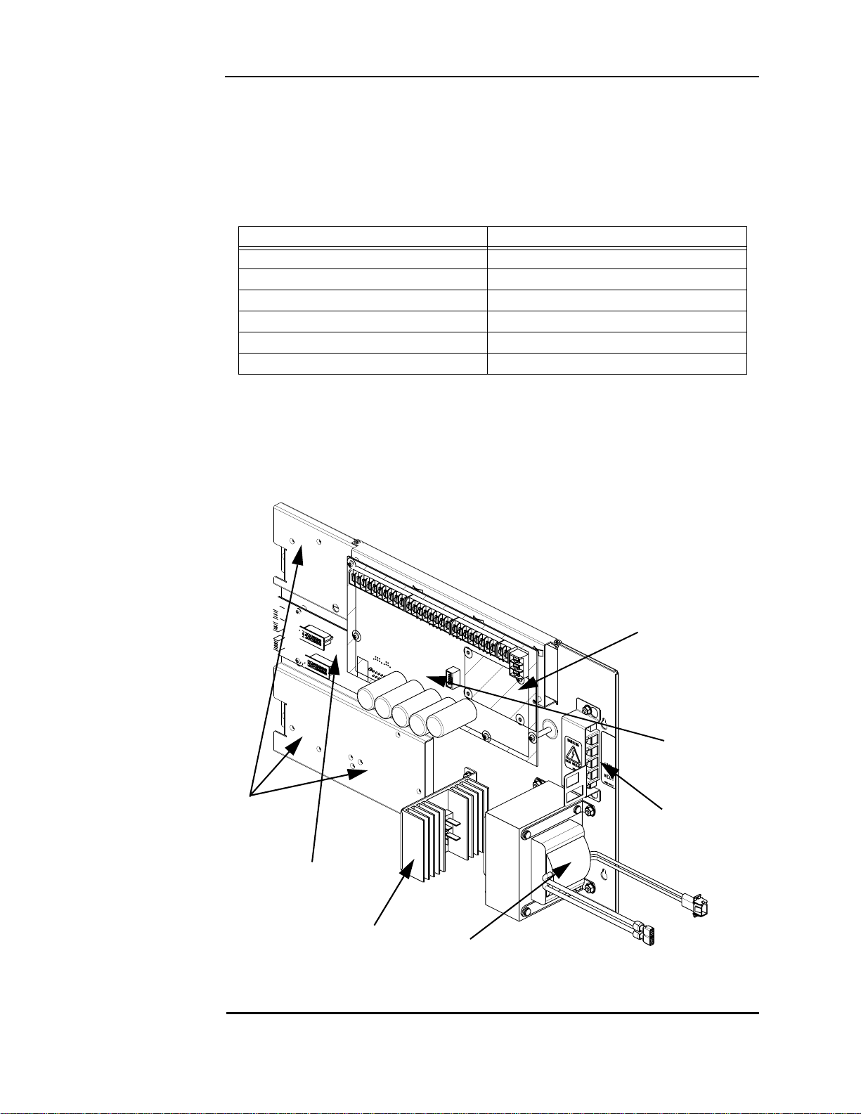
Main system supply (MSS)
Top Bay
PDI card
Rectifier
Option Card
Blocks
Optional City Card
or Relay Card
Mounting Space
Transformer
AC Block
MSS
Overview The MSS is the power source for the FACP. It provides 24 VDC card power to the 4010ES.
T able 2-11 lists the MSS capabilities.
The MSS also performs standard fire alarm functions, such as brownout detect, battery transfer,
battery recharge, earth fault detection, and power limiting per UL 864. It is shipped, installed,
and connected in the 4010ES panel. Figures 2-5 and 2-6 illustrate a 4010ES MSS.
Table 2-11. MSS capabilities
MSS with IDNet MSS without IDNet
8 A of available power 8 A of available power
4 Class A NACs 4 Class A NACs
Battery charger (Note) Battery charger (Note)
1 AUX relay (2 A, 32 V) 1 AUX relay (2 A, 32 V)
1 AUX power tap (2 A) 1 AUX power tap (2 A)
Single channel, Dual Isolated Loop IDNet+
Note: The 4010ES can hold a maximum of 33 Ah batteries in the one-bay box and 50 Ah in the two-
bay box. The MSS charger is listed for 110 Ah UL and 50Ah ULC.
Note: The type of MSS you get depends on the base panel selected. See Chapter 3, “Panel
Configurations.”
Figure 2-5. MSS shown with IDNet
Continued on next page
2-9
Page 22
Main system supply (MSS), continued
Overview
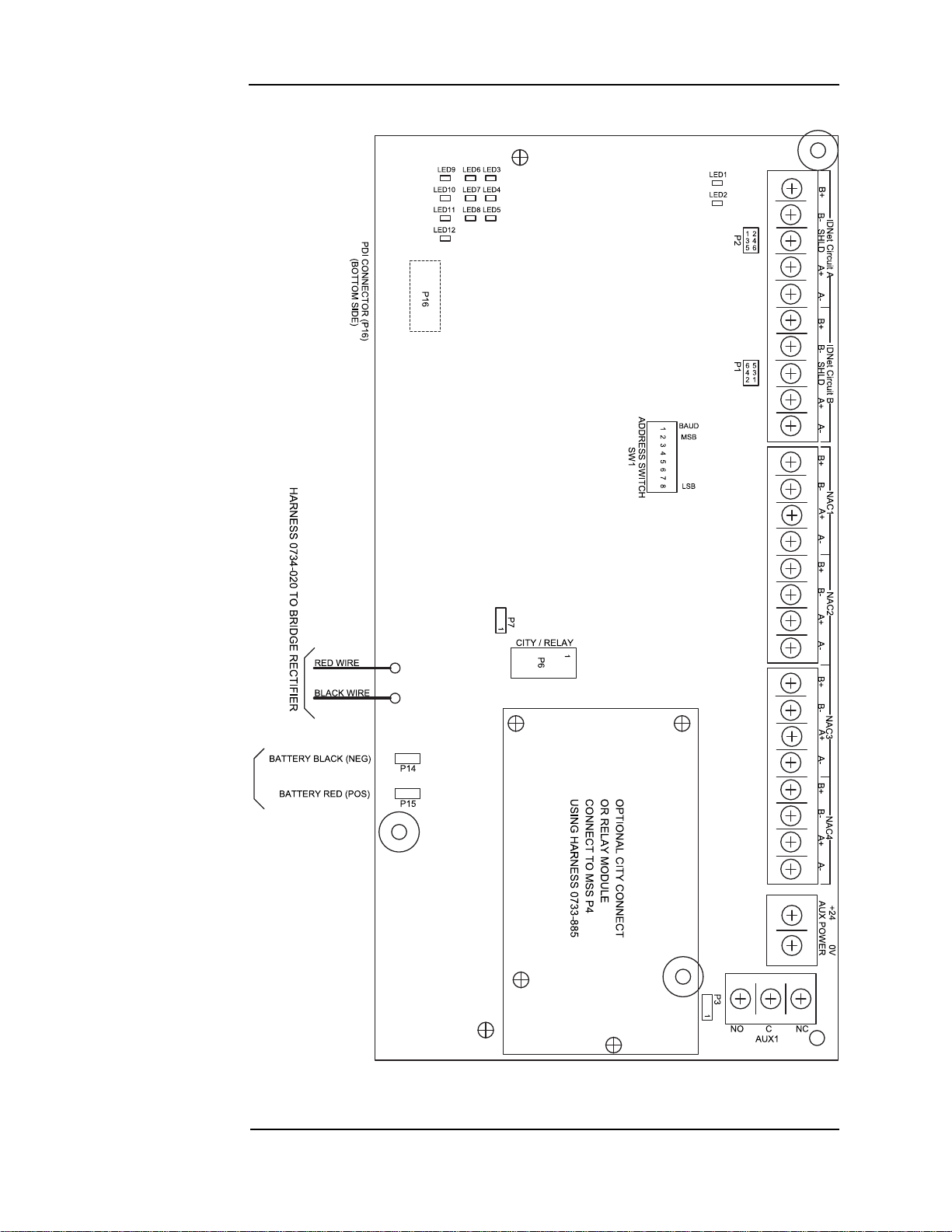
Figure 2-6. MSS LEDS and switches
2-10
Page 23

Main system supply (MSS), Continued
MSS LEDs and jumpers
Tables 2-12 and 2-13 list the details associated with the LEDs and jumpers on the MSS.
Table 2-12. MSS LED Functions and Indications
LED number Silkscreen name Status
LED1 IDNet POS. EARTH ON = IDNet POS. EARTH (Note)
LED2 IDNet NEG. EARTH ON = IDNet NEG. EARTH (Note)
LED3 IDNet
LED4 IDNet CIRCUIT A ON = CLASS A / OPEN TRBL
LED5 IDNet CIRCUIT B ON = CLASS A / OPEN TRBL
LED6 4100 COMMS ON = COMM LOSS
LED7 GENERAL POWER TRBL
LED8 AC POWER ON = MSS POWER FROM AC MAIN
LED9 NAC1 NAC1 TRBL or NAC1 “ON”
LED10 NAC2 NAC2 TRBL or NAC2 “ON”
LED11 NAC3 NAC3 TRBL or NAC3 “ON”
STEADY = NO DEVICE DETECTED
BLINK = SHORT CIRCUIT TRBL
STEADY = OVERCURRENT
SINGLE BLINK = POS. EARTH
DOUBLE BLINK = NEG. EARTH
TRIPLE BLINK = BATTERY TRBL
QUAD BLINK = CHARGER TRBL
LED12 NAC4 NAC4 TRBL or NAC4 “ON”
Note: The IDNet circuit on the MSS is electrically isolated and has its own earth fault detection circuit.
The IDNet earth fault detection circuit detects a 10K Ohms (or less) stray impedance to earth
ground.
Table 2-13. MSS Jumper Functions
Jumper
number
P1 IDNet CIRCUIT B
P2 IDNet CIRCUIT A
P3 EARTH DETECT (Note 2)
P7
Note 1. When jumpers are set for Class B (Style 4) on IDNet, you may use both the B-side and the A-side
to wire devices. Thus, for Circuit B, you can have two pairs of wires per side or four branches per
circuit.
2. Only one power module should be set for earth fault monitoring for each location within a system.
Normally, the MSS is set to monitor for earth faults. The earth fault detection circuit will detect a
10K Ohms (or less) stray impedance to earth ground. The expansion battery charger (XBC,
4081-9306, -9308) may also be set to monitor for earth faults. When an XBC is used to provide
battery backup for a 4010ES panel, disable the earth fault detection on the XBC.
Silkscreen name Position Function
LOW BATTERY
DISCONNECT
CLASS B (STYLE 4) (Note 1)
CLASS A (STYLE 7)
CLASS B (STYLE 4) (Note 1)
CLASS A (STYLE 7)
ENABLE
DISABLE
DISABLE (DOMESTIC)
ENABLE (CANADA)
1-3, 2-4
3-5, 4-6 (DEFAULT)
1-3, 2-4
3-5, 4-6 (DEFAULT)
1-2 (DEFAULT)
2-3
1-2 (DEFAULT)
2-3
2-11
Page 24

Main system supply (MSS), continued
MSS specifications
Table 2-14 lists the specifications for the MSS.
Table 2-14. Input and output specifications
AC input specifications
MSS in 120V FACP 4 A maximum
120 VAC @ 60 Hz, nomi nal (Note 1)
MSS in 220/240V FACP 2 A maximum
220/230/240 VAC @ 50 or 60 Hz (Note 1)
DC output specifications
All MSSs Minimum: 19.9 VDC (special applications)
Maximum: 31.1 VDC
Ripple: 2 VDC p-p @ full load (8 A)
MSS with IDNet output (see
note)
Battery charger specification s (Note 3)
Input voltage range 21-33VDC
Output float voltage
High voltage output 29.1 V @ 3.3 A
Output current limit 1.4 A for 6.2 - 18 Ah battery
30V or 35V (Note 2)
o
27.4 VDC ±500 mV @ 20
24 mV to -36 mV/×C (32
C, temperature compensated at -
o
F to 120oF or 0oC to 49oC)
3.3 A (default; for 18-50 Ah battery- Canadian; for 18-110 Ah
battery - U.S.)
Note: 1. The MSS detects a low or missing AC input and switches to batteries automatically. The system
returns to AC when it detects the presence of acceptable AC levels for a minimum of 30 seconds. AC
wiring must run from a dedicated AC branch circuit, and the breaker/wiring must be sized according
to local codes.
2. When it is necessary to activate large numbers of output devices on IDNet peripherals, such as
piezo sounders, the output voltage increases to 35V to provide sufficient voltage at the end of line to
activate the piezo. The higher voltage state is an alarm condition for the purpose of standby battery
calculation. The 30V output is the normal condition, and is used to prolong battery standby. The CPU
will activate the boost feature when 10 LED, Piezo or other outputs are activated.
3. The battery circuit is supervised for overcurrent, low battery and missing or depleted battery.
Continued on next page
2-12
Page 25

Main system supply (MSS), continued
MSS
specifications
Tables 2-15 and 2-16 list the battery current draw for the MSS. The assumed voltage is
24 VDC, which is rated battery voltage for lead-acid type batteries.
Table 2-15. MSS with IDNet current specifications
Standby conditions (Note 1)
No alarms (NACs normal); TBL relay activated; IDNet LED ON, No IDNet devices connected 140 mA 190 mA
Add to above for each additional set of 50 IDNet devices in standby 40 mA
Total current for fully loaded IDNet channel (248 devices) in standby 339 mA 450mA
Alarm conditions (Note 2)
4 NACs ON (Note 3); TBL Relay Activated; IDNet LED ON, No IDNet devices connected 165 mA 220 mA
Add to above for each set of 50 IDNet devices in alarm 50 mA
Add to above for 20 LEDs ON 40 mA
Total current for a fully loaded IDNet channel (248 devices) in alarm (20 LEDs ON) 453 mA 600 mA
Current
(battery standby 24V)
Current
(battery standby 24V)
Current
(max)
Current
(max)
Table 2-16. MSS without IDNet current specifications
Standby conditions (Note 1)
No Alarms (NACs normal); TBL Relay activated 70 mA 110mA
Alarm Conditions (Note 2)
4 NACs ON (Note 3); TBL Relay activated 100 mA 150 mA
Current
(battery standby 24V)
Current
(battery standby 24V)
Current
(max)
Current
(max)
Note: 1. Additional standby conditions: Auxillary relay activated, power trouble LED on, battery charger off,
auxiliary power load = 0 mA.
2. Additional alarm conditions: Auxillary relay activated, power trouble LED on, battery charger off,
auxiliary power load = 0 mA, NAC alarm load = 0 mA, IDNet = 35 V.
3. Notification power must also be taken into account for alarm current. Consult the notification
appliances, used installation manuals to determined the current draw for each appliance used.
The notification appliance circuits on the MSS are rated for special application and for
regulated 24 VDC operation per UL864, 9th Edition.
When used with the notification appliances listed in Table C-1 (Appendix C) or Table D-1
(Appendix D), each NAC is rated for 3 A, and total MSS capacity is rated at 8 A. This rating is
the UL864 special application rating. Appliances listed in Tables C-1 or D-1 are synchronized
per UL864 between all NACs on the MSS, and any NACs on a MSS or 4009As within the
same 4010ES system.
When using notification appliances not listed in Tables C-1 or D-1, each circuit is rated for 2 A
maximum, with a total notification appliance load of 4 A per MSS. This rating is the UL864
regulated 24 VDC rating. Synchronization of strobes and other appliances requires use of the
associated, listed, compatible synchronization module. Consult the supplier of notification
appliances for synchronization limits and details.
Simplex appliances (Table C-1) may not be mixed with Wheelock appliances (Table D-1) on a
single power supply. A 4010ES system with mix of appliances from Tables C-1 and D-1 will
not meet the UL864 9th Edition requirement for visual synchronization (10 milliseconds)
between power supplies. Appliances listed in Table C-1 will be consistently out of visual sync
with appliances in Table D-1 by about 30 milliseconds. Appliances listed Ta ble C-1 will be
notably out of audible sync with appliances in Table D-1 by a consistent time, Wheelock
leading by 1/2 second. In order to meet the requirements for visual and audible sync system
wide, all appliances in the system must be exclusively from either Table C-1 or D-1. Nonpulsing, linear-type notification appliances, such as horns or bells may be used up to the full
rating (3 A/NAC, 8 A total for the MSS).
2-13
Page 26
48-LED Module
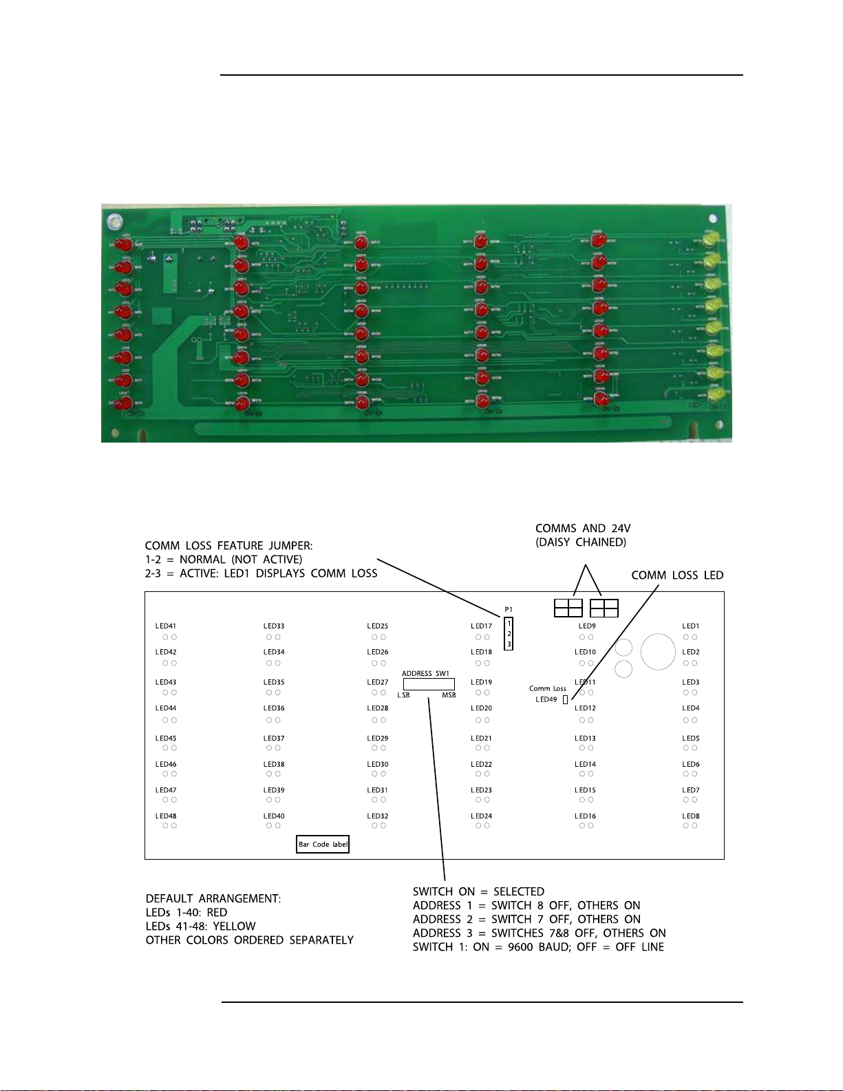
Overview The 48-LED Module (Figure 2-7) comes pre-installed inside some base configurations of the
4010ES panel. Each LED can be associated with a point, or group of points. By default, the
module is supplied with red LEDs, except for the last column which has yellow LEDs. All of
the LEDs can be replaced by different color LEDs. Refer to Chapter 4, “LED Kits for the 48LED Module,” for a list of LED kits. Refer to Chapter 5, “Installing 4010ES Systems,” for
instructions on replacing LEDs.
Figure 2-7. 48-LED Module (front view)
Figure 2-8 outlines what the different LEDs, jumpers and switches represent.
Figure 2-8. 48-LED Module LEDs, jumper s an d switches (rear view)
2-14
Page 27

48-LED Module, continued
48-LED Module specifications
Standby current Current
LED controller circuit 20 mA
Add to above for each additional LED that is on 1.89 mA
Total current for fully loaded 48-LED Module 111 mA
Maximum alarm current
LED controller circuit 20 mA
Add to above for each additional LED that is on 2.39 mA
Total current for fully loaded 48-LED Module 135 mA
Table 2-17. 48-LED Module current specifications
Current
2-15
Page 28

System power
Main system power
Backup batteries A pair of 12V sealed lead acid batteries are used as a backup power source in the event of AC
The 4010ES FACP is powered primarily by the MSS. The MSS draws power from the main
power line, via an AC block, a transformer and a rectifier (Figure 2-5). In the case of main
power failure, backup power is provided by backup batteries.
failure. The backup batteries are ordered and shipped separately from the 4010ES system. They
are installed at the bottom of the 4010ES back box.
Batteries larger than 33 Ah for a one-bay 4010ES and 50 Ah for a two-bay 4010ES can be
used. However, they must be accepted and installed per UL and local authority requirements
using 4100-5128 Battery Distribution Terminal Block. The connection from the battery box to
the 4010ES panel must be within 20 feet and in conduit.
For 50 Ah external batteries with a one-bay box, use box 2081-9282 Remote Battery Cabinet
(Red). For 110 Ah external batteries with a one or two-bay box, use box 2081-9280 Remote
Battery Cabinet (Red).
2-16
Page 29

Chapter 3
Panel configurations
Introduction The 4010ES comes in either in a one-bay or a two-bay configuration. Each of these can be
ordered in a variety of base systems to satisfy various market needs.
In this chapter This chapter covers the following topics:
Topic Page
One-bay 4010ES Panels 3-2
Two-bay 4010ES Panels 3-6
3-1
Page 30
One-bay 4010ES Panels
With 48 LED Module
Without 48 LED Module
Overview The basic components are shipped pre-assembled inside the 4010ES panel. The optional
components need to be ordered and installed separately.
The one-bay 4010ES panel comes in three configurations. Table 4-1 of Chapter 4, “Orderable
Panels and Devices,” lists the basic components that are shipped with each of the three
configurations.
Note: The dead front on a one-bay 4010ES panel is different for 48-LED Module configurations, as seen in
Figure 3-1. See Figure 3-2 for detailed diagrams of one-bay 4010ES panels.
Figure 3-1. One-bay dead front with and without 48-LED Module
3-2
Continued on next page
Page 31

One-bay 4010ES Panels, continued
Without 48-LED Module
With 48-LED Module
Glass Door
Glass Door
Dead
Front
Dead
Front
CPU
CPU
Back
Box
Back
Box
Option Card
Mounting Space
Option Card
Mounting Space
48-LED
Module
Overview
Figure 3-2. One-Bay 4010ES Panel
3-3
Page 32

One-bay 4010ES Panels, continued
Optional modules In addition to the basic modules, optional modules can be installed inside the one-bay 4010ES
panels. The types of modules available depend on the panel configuration as well as the
accessibility and availability of the power distribution interface (PDI) blocks.
Note: Out of four PDI blocks in the top bay PDI card, three are available since the MSS card utilizes one
(Figure 2-5).
Table 3-1 lists the optional modules that can be installed insid e the different configurations of
the 4010ES panels. Refer to the user manual associated with each card for specifications and
installation instructions. The list of these manuals is available in Table 4-3 in Chapter 4,
“Orderable Panels and Devices.”
Table 3-1. Optional modules
Optional modules Description Blocks
4010-9818 Network Media Card Wired (Mounts on 4010-9902 and 4010-9922) none
4010-9819 Network Media Card Fiber Optic (Mounts on 4010-9902 and 4010-9922) none
4010-9901 VESDA Interface Card 1
4010-9902 and 4010-9922 4120 Network Interface Card 2
4010-9903 and 4010-9924
(Note 2)
4010-9904 and 4010-9925
(Note 2)
4010-9905 and 4010-9926
(Note 2)
4010-9906 and 4010-9927
(Note 2)
4010-9908 4-Point Flat AUX Relay (2 A) 1
4010-9909 City Connect Card with Disconnect Switches (MSS mounted) none
4010-9910 City Connect Card without Disconnect Switches (MSS mounted) none
4010-9911 Alarm Relay Card (MSS mounted) none
4010-9912
4010-9913 SafeLinc Internet Interface (FPII) Card 2
4010-9914 Building Network Interface Card (BNIC) 2
4010-9916 25 VDC Voltage Regulator Card 1
4010-9917 MX Digital Loop Card (international models only) 2
4010-9918 Dual RS232 Card 1
4010-9919
4010-9920 8 Zone Initiating Device Circuit, Class B 2
4010-9921 8 Zone Initiating Device Circuit, Class A 2
4010-9929 IDNet 2+2 Card 1
4120 Network Interface w/ Modem physical Bridge Style 4 2
4120 Network Interface w/ Modem physical Bridge Style 7 2
4120 Network Interface TCP/IP physical Bridge Style 4 3
4120 Network Interface TCP/IP physical Bridge Style 7 3
SDACT Card
(Mounts in top bay Block D only)
TrueInsight Remote Service Gateway (Perle)
(mounts on dead front)
none
1
Note: 1. Consult your local sales office to determine which modules are available in your area.
2. Physical bridge cards must also be installed with a network interface card. Therefore, the 4010ES
one-bay systems do not have enough option card space left to install a physical bridge after a NIC is
added.
3-4
Page 33

One-bay 4010ES Panels, continued
Back box mechanical specifications
Back boxes ship with the panel and can only be ordered separately as a service part. Table 3-2
lists the specifications for the one-bay back boxes.
Table 3-2. Back box specifications
PID number Height Width Depth
699-467 (Platinum)
22 in. (559 mm) 24 in. (610 mm)
699-466 (Red)
6-29/32 in.
(175 mm)
Depth with
door
11-11/16 in.
(297 mm)
3-5
Page 34

Two-bay 4010ES Panels
#05#ARD
/PERATOR)NTERFACE
'ROUNDING3TRAP
$EAD&RONT,ATCH
0IEZO
%THERNET3ERVICE0ORT
'ROUNDING3TRAP
'ROUNDING3TRAP
#05#ARD
)NFO!LARM5SER
)NTERFACE
)NFO!LARM!PPLIQUE
3TANDARD5SER)NTERFACE
)NFO!LARM5SER)NTERFACE
$EAD&RONT,ATCH
Overview A two-bay system is used when more option card space is required than is given in a one-bay
system, or when InfoAlarm is the primary display. Refer to Figure 2-4 for an illustration of the
InfoAlarm interface.
The basic components of the two-bay panels are the same as for the one-bay panels and are preinstalled in the top bay. The expansion bay contains another PDI card with eight available
blocks. Those can be used to connect optional modules to the 4010ES panels. The Expansion
Bay PDI card comes pre-installed inside the two-bay panel.
See Figures 3-3 through 3-5 for two-bay 4010ES diagrams.
Figure 3-3. Two-bay, standard and InfoAlarm dead fronts
Continued on next page
3-6
Page 35

Two-bay 4010ES Panels, continued
CPU
Dead Front
Expansion PDI
MSS
Back Box
Glass Door
Top Bay
Overview
Figure 3-4. Two-bay 4010ES Panel with standard user interface
Continued on next page
3-7
Page 36

Two-bay 4010ES Panels, continued
MSS
Expansion PDI
InfoAlarm
Interface
Dead Front
CPU
Glass Door
Back Box
Top Bay
Overview
Figure 3-5. Two-bay 4010ES Panel with InfoAlarm interface
3-8
Page 37

Two-bay 4010ES Panels, continued
Optional modules The same optional modules can be used with the two-bay panels as with the one-bay panels.
For a complete list of optional components, see Chapter 4, “Orderable Panels and Devices.”
Back box mechanical specifications
Table 3-3 lists the specifications for the two-bay back boxes.
Table 3-3. Back box specifications
PID number Height Width Depth
699-465 (Platinum)
40.0 in. (1016 mm) 24 in. (610 mm)
699-464 (Red)
6-29/32 in.
(175 mm)
Depth with
door
11-11/16 in.
(297 mm)
3-9
Page 38

Page 39

Chapter 4
Orderable panels and devices
Introduction The following chapter lists the 4010ES panels and optional modules that can be ordered. It
also lists the installation manuals that are associated with each optional device.
In this chapter This chapter covers the following topics:
Topic Page
Panels 4-2
Optional modules 4-3
4-1
Page 40

Panels
One-bay 4010ES Panels
Table 4-1. One-bay 4010ES systems
Panel PIDs
4010-9401 Red
4010-9402 Platinum
4010-9501 Red
4010-9502 Platinum
4010-9403 Red
4010-9404 Platinum
4010-9405 Red
4010-9406 Platinum
4010-9503 Red
4010-9504 Platinum
Panel
color
Panel language
and AC voltage
English
120V
English
220V-240V
English
120V
French
120V
English
220V-240V
CPU with a 2 x 40
display and a piezo
Standard
operator
interface
Panel components
MSS with an IDNet
channel
MSS (No IDNet)
Three free
option blocks
One free
option block
48-LED Module
(door-mounted)
One MX Loop
Option Card pre-
installed (4010-
Two-bay 4010ES Panels
T able 4-2. Two-bay 4010ES systems
Panel PIDs
4010-9421 Red
4010-9422 Platinum
4010-9521 Red
4010-9522 Platinum 10 free
4010-9425 Red
4010-9426 Platinum
4010-9525 Red
4010-9526 Platinum -4010-9523 Red
4010-9524 Platinum
4010-9527 Red
4010-9528 Platinum
4010-9529 Red
4010-9530 Platinum
4010-9423 Red
4010-9428 Platinum
4010-9430 Platinum French 120V
Panel
color
Panel
language and
AC voltage
English 120V
English
220V-240V
English 120V
English
220V-240V
English 120V
CPU with a 2 x 40
display and a piezo
CPU
CPU with a 2 x 40
display and a piezo
CPU
CPU with a 2 x 40
display and a piezo
Panel components
Standard operator
interface
InfoAlarm interface
(display and piezo)
Standard operator
interface
InfoAlarm interface
(display and piezo)
Standard operator
interface
MSS with an
IDNet channel
MSS
(No IDNet)
MSS with an
IDNet channel
option
card blocks
11 free
option card
blocks
7 free option
card blocks
9 free option
card blocks
7 free option
card blocks
10 free
option card
blocks
One IDNet 2+2 Card
pre-installed
(4010-9929)
One IDNet 2+2 Card
pre-installed (4010-
One IDNet 2+2 Card
pre-installed (4010-
Two MX Loop Option
Cards pre-installed
(4010-9917)
One MX Loop Option
Card pre-installed
(4010-9917)
Two MX Loop Option
Cards pre-installed
(4010-9917)
One IDNet 2+2 Card
pre-installed (4010-
48 LED Module (door
mounted)
---
9917)
9929)
9929)
--
9929)
4-2
Page 41

Optional modules
Local optional modules
T able 4-3. Local optional modules installation instructions
PID Description
4010-9818 Wired Network Media Card 579-956
4010-9819 Fiber Optic Network Media Card 579-956
4010-9901 4010ES/4100/4120-Series VESDA Card 579-963
4010-9902
and
4010-9922
4010-9903
and
4010-9924
4010-9904
and
4010-9925
4010-9905
and
4010-9926
4010-9906
and
4010-9927
Network Interface Card
Style 4 Network Modular Physical Bridge
Style 7 Network Modular Physical Bridge
Style 4 Network TCP/IP Physical Bridge
Style 7 Network TCP/IP Physical Bridge
Installation
instructions
579-956
574-041
579-818
579-184
574-041
579-818
579-184
574-041
579-818
579-184
574-041
579-818
579-184
574-041
4010-9908 4-Point Flat AUX Relay Card 5 79-220
4010-9909 City Connect Module with Disconnect Switches (MSS mounted) 579-955
4010-9910 City Connect Module without Disconnect Switches (MSS mounted) 579-955
4010-9911 Alarm Relay Modul e (MSS mounted) 579-955
4010-9912 SDACT 579-954
4010-9913 SafeLinc Internet Interface (FPII) 579-349
4010-9914 B uilding Network Interface Card (BNIC) 579-949
4010-9916 25 VDC Voltage Regulator Module (international only) 579-812
4010-9917 M X Digital Loop (international only) 579-833
4010-9918 Dual RS232 Module 574-910
4010-9919 TrueInsight Remote Service Gateway 579-953
4010-9920 8 Zone Initiating Device Circuit, Class B 579-205
4010-9921 8 Zone Initiating Device Circuit, Class A 579-991
4010-9929 IDNet 2+2 Module 579-1170
4-3
Page 42

Optional modules, continued
Remote devices
Table 4-4. Remote power and notification devices installation instructions
PID Description
4010-9818 Wired Network Media Card 579-956
4010-9819 Fiber Optic Network Media Card 579-956
4009-9401 4009T TrueAlert Controller 574-762
4081-9306
4009-9201 4009A 120V 574-181
4009-9202CA 4009A 120V ULC-listed model 574-181
4009-9301 4009A 240V 574-181
4009-9813 Transponder Interface Card (TIC) 579-875
4100-5120 120 V Domestic TPS 579-875
4100-5121 120 V Canadian TPS 579-875
4100-5122 220-240 V International TPS 579-875
4100U External Battery Charger 120V (with cabinet,
holds 11 Ah batteries)
4009 Remote TrueAlert Power Supply (TPS)
Installation
instructions
579-268
Table 4-5. Remote display and annunciation devices installation instructions
PID Description
4100-9401 Remote InfoAlarm - Red 579-687
4100-9402 Remote InfoAlarm - Beige 579-687
4100-9421 Remote InfoAlarm (French) - Red 579-687
4100-9422 4100-9422 Remote InfoAlarm (French) - Beige 579-687
4100-9441 Remote InfoAlarm (international) - Red 579-687
4100-9442 Remote InfoAlarm (international) - Beige 579-687
4100-7401 24-Point I/O Graphic Module (requires mounting cabinet) 574-348
4606-9102 4010ES RUI LCD Annunciator 579-977
Installation
instructions
4-4
Page 43

Optional modules, continued
Adjunct features
Table 4-6. Adjunct features
End user programming tools
PID Description
4081-9308
4190-9021
4190-9022
4190-9023 Right Port Modem for Exp Cabinet – Single Mode 579-831
4190-9024
4190-9025
4190-9026 Right Port Modem for Expansion Cabinet – Single Mode 579-831
4100U External Battery Charger 220/230/240 V (with
cabinet. Holds 110Ah batteries)
Red Fiber Modem Expansion Cabinet with Left Port
Modem – Single Mode
Beige Fiber Modem Exp Cabinet with Left Port Modem Single Mode
Red Fiber Modem Exp Cabinet with Left Port Modem –
Multimode
Beige Fiber Modem Exp Cabinet with Left Port Modem Multimode
T able 4-7. End user programming tools
PID Description
Installation
instructions
579-268
579-831
579-831
579-831
579-831
LED kits for the 48-LED Module
4100-0292 Custom Label Editing (USB Dongle)
4100-0295 Port Vectoring Setup and Control (USB Dongle)
4100-0296 User Group/Passcode Editing (USB Dongle)
4100-0298 Walktest Configuration Setup and Control (USB Dongle)
4100-8802 Programming Unit Software
T able 4-8. LED kits for the 48-LED Module
PID Description
4100-9843 8 Yellow LEDs
4100-9844 8 Green LEDs
4100-9845 8 Red LEDs
4100-9855 8 Blue LEDs
4-5
Page 44

4-6
Page 45

Chapter 5
Installing 4010ES systems
Introduction This chapter describes how to mount the 4010ES back boxes to a wall, and install basic
system components into the boxes.
Before beginning the installation, review this chapter to get a sense of the types of bays and
modules that make up the FACP.
IMPORTANT: Verify ES Panel Programmer, Executive, and Slave Software compatibility
when installing or replacing system components. Refer to the technical
support website for up-to-date compatibility information.
In this chapter This chapter covers the following topics:
Topic Page
Mounting the panel 5-2
General field wiring guidelines 5-5
Connecting 4010ES basic components 5-7
RUI wiring 5-11
Installing the optional modules 5-13
Address configuration DIP switch 5-14
Connecting main system power 5-16
5-1
Page 46

Mounting the panel
POTPOT
RESERVED
FOR
BATTERIES
(SEE NOTE 6)
ADDITIONAL
BACK BOX
USE 4 HOLES TO
SECURE BACKBOX
TO THE WALL
USE 4 HOLES TO
SECURE BACKBOX
TO THE WALL
24”
(610 mm)
3 17/32”
(90 mm)
5 17/32”
(140 mm)
16”
(406 mm)
See Notes 3 and 5
6 29/32”
(175 mm)
22”
(559 mm)
(ONE
BAY)
ALIGNMENT MARKERS
FOR WALL STUDS:
6” (152 mm)
4” (102 mm)
WAL L
WAL L
PANEL
FRONT
Installing the back box
Store the system electronics containers in a safe, clean, and dry location until the back box
installation is completed and you are ready to install additional modules. Make certain that you
have the necessary hardware before you begin the installation procedure.
Install the back box as shown in Figure 5-1. Use the holes in the back box to secure it to the
wall.
Note: • Conductor entrance and routing restrictions apply to power-limited systems only.
• While the pre-installed system components may be left in the backbox during installation, due to
the danger of metal fragments falling into electronics, it is recommended to remove the dead front
and any bay pans in the system.
• For surface or flush mounting to a wooden wall structure, the back box must be attached with four
3/8-inch-diameter x 1-½-inch-long (9.5 mm x 38 mm) fasteners and four 3/8-inch-diameter (9.5
mm) washers.
• For surface mounting, secure the box to the wall using the tear-drop mounting holes on the back
surface. For flush and semi-flush mounting, secure the box to the wall studs using the indicated
areas (dents in the metal) on the sides of the box. Note that the front surface of the back box must
protrude at least three inches from the wall surface for semi-flush installations.
• Power-limited systems have entrance and routing restrictions for field wiring. See section
“General Field Wiring Guidelines” on page 5-5 for more details.
Figure 5-1. Back box installation
Notes:
1. Dimensions shown are typical for all surface and semi-flush installations.
2. Use suitable punch when conduit is required. Knockouts are not provided. Locate and create on-site
as required during installation.
3. A minimum clearance of 5 inches (127 mm) from the hinge side is required to provide a maximum
door opening of 90 degrees.
4. Do not install any power-limited wiring in the shaded area of the back box as shown in Figure 5-1.
This area is reserved for non power-limited devices and circuits. for example, AC power, batteries,
and city circuits. The non power-limited area is determined by the internal barriers, but is always
below and to the right of these barriers.
5. Minimum distance between boxes is 3 1/4 inches (83 mm). Maximum distance between boxes is 10
inches (254 mm).
5-2
Page 47

Mounting the panel, continued
,%$
-ODULE
'ROUNDING3TRAP
/PERATOR)NTERFACE
#05
#ARD
$EAD&RONT,ATCH
0IEZO
,%$-ODULE/VERLAY
%THERNET3ERVICE0ORT
$EAD&RONT,ATCH
#05
#ARD
0IEZO
%THERNET3ERVICE0ORT
'ROUNDING3TRAP
/PERATOR)NTERFACE
One-Bay
Two-Bay
Top
Bottom
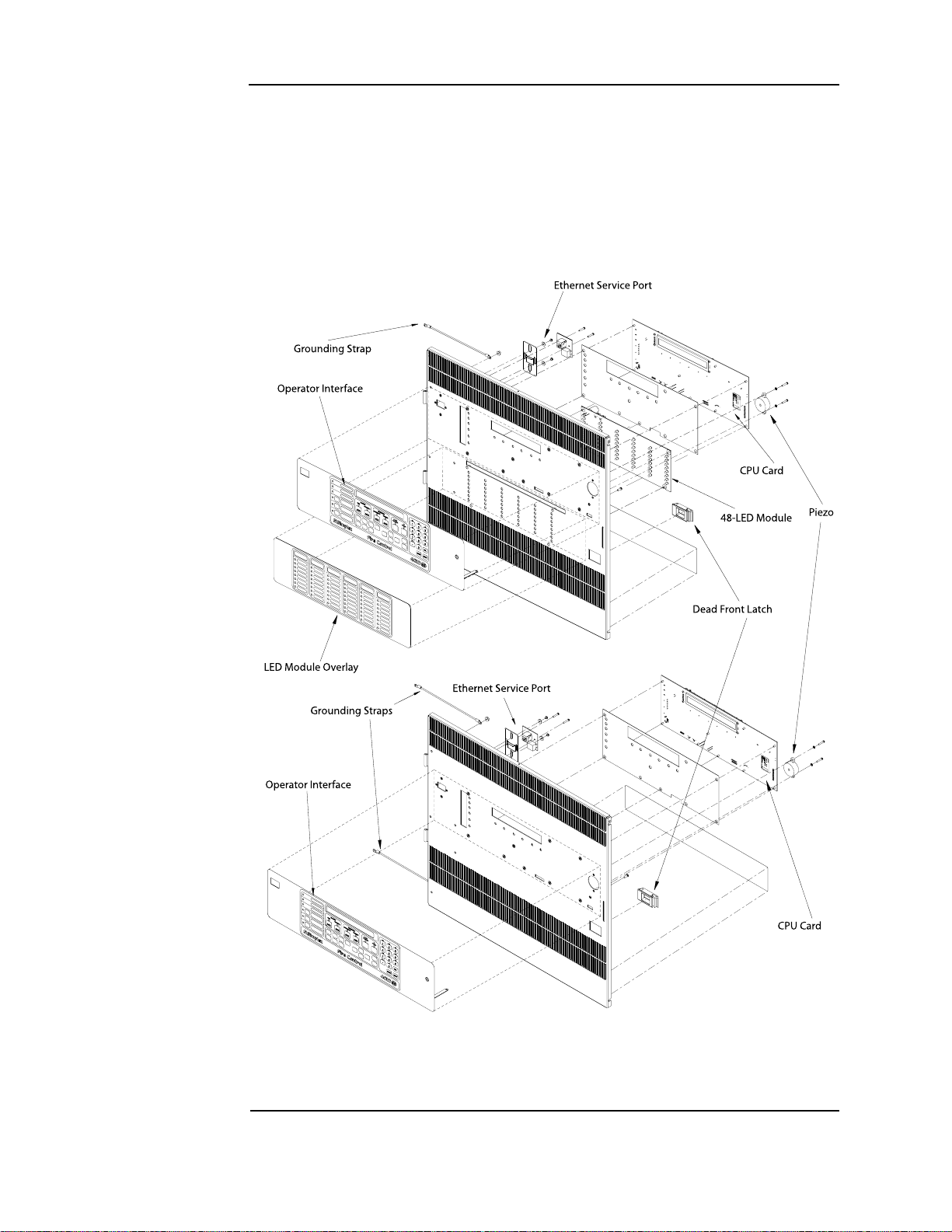
Attaching the dead front
To attach the 4010ES panel dead fronts containing the operator interface and the 48-LED
Module (where applicable), perform the following steps:
1. Align the dead front hinges with the hinge pins on the back box, and slide the door down
onto the hinge pins.
2. Attach the two grounding straps to the back box with the # 6 hex flange nuts. See Figure 5-3.
The grounding straps should already be attached to the dead front.
Figure 5-2. 4010ES dead fronts
Figure 5-3. Dead front grounding straps
5-3
Page 48

Mounting the panel, continued
One-bay
Two-bay
Attaching doors To attach the glass doors (Figure 5-4) to the cabinet, follow the steps below:
1. Align the door hinges with the hinge pins on the back box, and slide the door down onto the
hinge pins.
2. Attach the two grounding straps to the back box with the # 6 hex flange nuts. The grounding
straps should already be attached to the door.
Note: The hinge pins for the glass door are located higher and further to the side than the dead front hinge
pins.
Figure 5-4. One-bay and Two-bay glass doors
5-4
Page 49

General field wiring guidelines
NON-POWER LIMITED
WIRING AREA
POWER LIMITED
WIRING AREA
Power-limited guidelines
For wiring guidelines, see the applicable installation documentation or contact your authorized
Simplex Product supplier. Make sure these guidelines are accounted for before wiring for
power-limited systems:
• Non-power limited field wiring (AC power, batteries, city connection) must be installed
and routed in the shaded areas shown in Figure 5-5.
• Power-limited field wiring must be installed and routed in the non-shaded areas shown in
Figure 5-5, with the exception of city wiring.
• Excess slack should be kept to a minimum inside the back box enclosure. The wiring
should be neatly dressed and bundled together using wire ties.
Figure 5-5. Field wiring guidelines
• Tie the wiring located between bays to the internal wiring troughs, if applicable.
• When powering remote units or switching power through relay contacts, power for these
circuits must be provided by a power-limited power supply listed for fire-protective
signaling use. An EOL relay must be used to supervise the auxiliary power circuit.
• Auxiliary power only: Supervision must be provided if the auxiliary power circuit is to be
wired as a power-limited circuit. In order to connect a circuit using power-limited wiring,
the devices being powered must all be addressable, or a UL listed EOL relay must be used
to supervise the circuit. Refer to Figure 5-6 for wiring directions for the EOL relay.
Continued on next page
5-5
Page 50

General field wiring guidelines, continued
2098-9739
END OF
LINE RELAY
TO AUX POWER
RED BLACK
LAST IDC
DEVICE
YELLOW
RESISTORIDC
Note: The 2098-9739 Relay is
used as an example.
Other UL Listed 24VDC
EOL relays can be used,
depending on the
application.
Power-limited
guidelines
Figure 5-6. The EOL relay
5-6
Page 51

Connecting 4010ES basic components
SERIAL SERVICE PORT (P11)
ETHERNET SERVICE PORT (J7)
KEYPAD MEMBRANE
Connecting the CPU and the operator interface
Note: All the basic components come pre-installed with the system. The connections are shown for
reference purposes.
To connect the CPU and the operator interface, follow the steps below:
1. Place the white spacer on the dead front.
2. Attach the CPU card and the piezo to the dead front, using metal screws provided.
3. Attach the Keypad Membrane cable of the operator interface to port P8 on the CPU card
(Figure 5-7). To do so:
a. Slide down the keypad connector shroud on the CPU card.
b. Insert the Keypad Membrane cable into the connector. Do not twist the flat cable.
c. Slide the shroud back up into the connector while holding the flat cable in place.
4. Attach the Ethernet connection board using the 734-232 RJ45 cable.
5. Attach the perle box using the 734-229 cable.
6. Connect port P9 or P10 of the CPU card to the dead front connection (P1) port on the topbay power distribution interface (PDI) card (Figure 5-7 and Figure 5-8). Use the
734-008 4-pin connector harness provided.
Figure 5-7. CPU card rear view
5-7
Continued on next page
Page 52

Connecting 4010ES basic components, continued
Back Box
MSS
Rectifier
Transformer
Top Bay
PDI
AC Terminal
Block
Connecting the
CPU and the
operator interface
Figure 5-8. Top bay
5-8
Page 53

Connecting 4010ES basic components, continued
Connecting the MSS
Follow the steps below:
1. Connect the MSS to the MSS (Block C) connector on the Top Bay PDI.
2. Attach the MSS to the back box using metal screws and standoffs.
3. Connect the rectifier to the Bridge HARN1 connectors on the MSS (Figure 5-9). The red
wire connects to the tab labeled “+” on the bridge. The black wire connects to the tab labeled
“-” on the rectifier. See Figure 5-8 for the location of the rectifier.
4. Connect the backup batteries to the Battery connectors on the MSS. The red wire connects
to the tab labeled "RED" on the MSS, the black wire connects to the “BLK” tab. The backup
batteries must be wired in series such that you have 24 V. Use the white wire provided to
bridge the batteries together. The batteries can be placed on the bottom of the 4010ES back
box.
Notes: 1. A fused harness is required to connect the backup batteries. That harness is shipped with the
panel. The mating spade lug on the battery should be 0.250 inch x 0.032 inches. If another size is
needed, you will need to replace the battery terminal connectors on the supplied battery harness.
2. One-bay system back boxes support up to 33 Ah batteries. Two-bay system back boxes support
up to 50 Ah batteries. If 50 Ah batteries are used, you must also order the 4100-0650 Battery
Shelf.
3. To minimize the power losses due to wiring from the battery box to the 4010ES, use at least a
12 AWG wire and keep the battery box at the minimum distance possible from the 4010ES.
Figure 5-9. MSS Bridge HARN1 connector
5-9
Page 54

Connecting 4010ES basic components, continued
00
!$$2%33 37
, 3" -3"
0
"AR #ODE ,ABEL
#OMM ,OSS
, %$
,%$
,%$
,%$
,%$
,%$
,%$
,%$
,%$
,%$
, %$
, %$
, %$
, %$
, %$
, %$
, %$
, %$
, %$
, %$
, %$
, %$
, %$
, %$
, %$
, %$
, %$
, %$
, %$
, %$
, %$
, %$
, %$
, %$
, %$
, %$
, %$
, %$
, %$
, %$
, %$
, %$
, %$
, %$
, %$
, %$
, %$
, %$
, %$
0 0
Connecting the 48-LED Module
Connect port P1 or P2 of the 48-LED Module card to either port P9 or P10 of the CPU card
(Figure 5-10). Use the 734-181 4-pin connector harness provided.
Figure 5-10. 48-LED Module rear view
Swapping LEDs
To swap any of the 48 LEDs on the 48-LED Module, follow the steps below:
1. Turn off AC power at the breaker, then remove the battery + connection at the panel.
2. Remove the 48-LED module from the dead front by following the steps below:
1. Disconnect any cables in P1 or P2 of the module
2. Remove the four screws holding the card to the dead front.
3. Remove the card from the dead front.
3. Pull out any necessary LEDs from the module.
4. Insert new LEDs in the vacated slots. For correct polarity, the flat line of the LED outline
on the card must line up with the flat side on the LED.
5. Re-attach the 48-LED module back on its spot on the dead front.
6. Re-attach the batteries and re-apply AC power to the 4010ES panel.
5-10
Page 55

RUI wiring
Overview The CPU card’s RUI channel supports the following devices:
• 4009T
• 4009 TPS
• 4602 Series RCU/SCU
• 4606-9102 Remote LCD Annunciator
• 4100-7400 Series Graphic Annunciators
• 4100-9400 Series Remote InfoAlarm Command Center
Wire from the CPU card’s RUI interface to the RUI terminal block (Figure 5-11). From there,
wire to each RUI device. The wiring may be Class A or Class B:
Class A wiring allows devices to communicate with the FACP even in the event of a single
open circuit somewhere in the loop. Class A wiring requires that two wires are routed from the
CPU card to each device, and then back again to the CPU card.
Class B wiring allows “T” tapping, and therefore requires less wiring distance per installation
than Class A.
Figure 5-1 1 . Lo ca tio n of the RUI termin a l blo ck
5-11
Continued on next page
Page 56

RUI wiring, continued
RUI
SHLD
RUI
SHLD
DASHED LINES ARE FOR
CLASS A OPERATION
1. Wire size must be
between 18 AWG (0.8231 mm
2
)
and 12 AWG (3.309 mm2).
2. Maximum wiring distance: 2,500 feet
(762 m) to device from CPU card.
3. Maximum “T” tapping length:
10,000 feet (3,048 m).
4. Maintain correct polarity on terminal
connections.
Do not loop wires under terminals.
RUI Device RUI Device
RUI A-
RUI A+
SHIELD
RUI B-
RUI B+
4010ES CPU Card
5. If Class A is not used, leave loop back wires from A+ to B+ and A- to B- on RUI terminal blocks.
6. Shield wire is not required. Twisted wire is recommended for improved noise immunity
Notes:
RUI
Terminal
Block
Overview Figure 5-12 depicts Class A and Class B wiring.
Figure 5-12. RUI wiring to the host panel
For more detailed field wiring information on each device, refer to its specific installation
instructions manual. See Chapter 4, “Orderable panels and devices,” for a list of instruction
manuals.
5-12
Page 57

Installing the optional modules
Overview Note: Skip this section if no optional modules need to be installed.
This page contains the general placement guidelines for the optional modules that can be used
with the 4010ES panels. If this information conflicts with the installation instructions for the
optional modules, the installation instructions take precedence. Refer to Table 4-3 in Chapter 4,
“Orderable panels and devices,” for a list of these installation instructions.
In addition to basic system components, the 4010ES panel has space on the PDI to
accommodate the following option card configurations:
1. One Two-Block 4 inch x 10 inch option card (such as a NIC or a SafeLINC card) and one 4
inch x 5 inch option card.
or
2. Three 4 inch x 5inch single-block option cards.
If the system is a two-bay system, an eight-block PDI card in the second bay allows for
additional mounting space beyond the three blocks in the top bay.
Note: Some systems come with option cards pre-installed. In these cases, the number of available option
card blocks is reduced. See the PID list table in Chapter 4 for details.
Installing oneblock and twoblock cards
The PDI cards are mounted to the back of each bay and carry power and data across all bays.
Use the following instructions and Figure 5-13 to mount cards into a 4010ES panel bay
1. Screw standoffs and washers to the appropriate holes in the back of the cabinet. These holes
must line up with the screw holes in the card.
2. Plug the card into the appropriate blind mating connector. Seat the card firmly onto the PDI
when installing to ensure complete insertion of the power connector into the PDI.
3. Secure the card to the standoffs with screws and washers.
Figure 5-13. Card connection to a PDI
5-13
Page 58

Address configuration DIP switch
18765432
ON
OFF
DIP Switches SWx-2 through
SWx-8 set the Card Address.
Figure shows an Address of 3.
4100 Comm. Baud Rate.
Switch (SWx-1)
Must Be Set to ON
Overview Addressable cards include a bank of eight DIP switches. From left to right (Figure 5-14) these
switches are designated as SWx-1 through SWx-8. The function of these switches is as
follows:
• SWx-1. This switch sets the baud rate for the internal 4010ES communications line
running between the card and the CPU. Set this switch to ON.
• SWx-2 through SWx-8. These switches set the card’s address within the 4010ES FACP.
Refer to Table 5-1 for a complete list of the switch settings for all of the possible card
addresses.
Note: You must set these switches to the value assigned to the card by the ES Panel Programmer.
Figure 5-14. DIP switch SWx
Continued on next page
5-14
Page 59

Address configuration DIP switch, continued
Address SW 1-2 SW 1-3 SW 1-4 SW 1-5 SW 1-6 SW 1-7 SW 1-8 Address SW 1-2 SW 1-3 SW 1-4 SW 1-5 SW 1-6 SW 1-7 SW 1-8
1 ON ON ON ON ON ON OFF 61 ON OFF OFF OFF OFF ON OFF
2 ON ON ON ON ON OFF ON 62 ON OFF OFF OFF OFF OFF ON
3 ON ON ON ON ON OFF OFF 63 ON OFF OFF OFF OFF OFF OFF
4 ON ON ON ON OFF ON ON 64 OFF ON ON ON ON ON ON
5 ON ON ON ON OFF ON OFF 65 OFF ON ON ON ON ON OFF
6 ON ON ON ON OFF OFF ON 66 OFF ON ON ON ON OFF ON
7 ON ON ON ON OFF OFF OFF 67 OFF ON ON ON ON OFF OFF
8 ON ON ON OFF ON ON ON 68 OFF ON ON ON OFF ON ON
9 ON ON ON OFF ON ON OFF 69 OFF ON ON ON OFF ON OFF
10 ON ON ON OFF ON OFF ON 70 OFF ON ON ON OFF OFF ON
11 ON ON ON OFF ON OFF OFF 71 OFF ON ON ON OFF OFF OFF
12 ON ON ON OFF OFF ON ON 72 OFF ON ON OFF ON ON ON
13 ON ON ON OFF OFF ON OFF 73 OFF ON ON OFF ON ON OFF
14 ON ON ON OFF OFF OFF ON 74 OFF ON ON OFF ON OFF ON
15 ON ON ON OFF OFF OFF OFF 75 OFF ON ON OFF ON OFF OFF
16 ON ON OFF ON ON ON ON 76 OFF ON ON OFF OFF ON ON
17 ON ON OFF ON ON ON OFF 77 OFF ON ON OFF OFF ON OFF
18 ON ON OFF ON ON OFF ON 78 OFF ON ON OFF OFF OFF ON
19 ON ON OFF ON ON OFF OFF 79 OFF ON ON OFF OFF OFF OFF
20 ON ON OFF ON OFF ON ON 80 OFF ON OFF ON ON ON ON
21 ON ON OFF ON OFF ON OFF 81 OFF ON OFF ON ON ON OFF
22 ON ON OFF ON OFF OFF ON 82 OFF ON OFF ON ON OFF ON
23 ON ON OFF ON OFF OFF OFF 83 OFF ON OFF ON ON OFF OFF
24 ON ON OFF OFF ON ON ON 84 OFF ON OFF ON OFF ON ON
25 ON ON OFF OFF ON ON OFF 85 OFF ON OFF ON OFF ON OFF
26 ON ON OFF OFF ON OFF ON 86 OFF ON OFF ON OFF OFF ON
27 ON ON OFF OFF ON OFF OFF 87 OFF ON OFF ON OFF OFF OFF
28 ON ON OFF OFF OFF ON ON 88 OFF ON OFF OFF ON ON ON
29 ON ON OFF OFF OFF ON OFF 89 OFF ON OFF OFF ON ON OFF
30 ON ON OFF OFF OFF OFF ON 90 OFF ON OFF OFF ON OFF ON
31 ON ON OFF OFF OFF OFF OFF 91 OFF ON OFF OFF ON OFF OFF
32 ON OFF ON ON ON ON ON 92 OFF ON OFF OFF OFF ON ON
33 ON OFF ON ON ON ON OFF 93 OFF ON OFF OFF OFF ON OFF
34 ON OFF ON ON ON OFF ON 94 OFF ON OFF OFF OFF OFF ON
35 ON OFF ON ON ON OFF OFF 95 OFF ON OFF OFF OFF OFF OFF
36 ON OFF ON ON OFF ON ON 96 OFF OFF ON ON ON ON ON
37 ON OFF ON ON OFF ON OFF 97 OFF OFF ON ON ON ON OFF
38 ON OFF ON ON OFF OFF ON 98 OFF OFF ON ON ON OFF ON
39 ON OFF ON ON OFF OFF OFF 99 OFF OFF ON ON ON OFF OFF
40 ON OFF ON OFF ON ON ON 100 OFF OFF ON ON OFF ON ON
41 ON OFF ON OFF ON ON OFF 101 OFF OFF ON ON OFF ON OFF
42 ON OFF ON OFF ON OFF ON 102 OFF OFF ON ON OFF OFF ON
43 ON OFF ON OFF ON OFF OFF 103 OFF OFF ON ON OFF OFF OFF
44 ON OFF ON OFF OFF ON ON 104 OFF OFF ON OFF ON ON ON
45 ON OFF ON OFF OFF ON OFF 105 OFF OFF ON OFF ON ON OFF
46 ON OFF ON OFF OFF OFF ON 106 OFF OFF ON OFF ON OFF ON
47 ON OFF ON OFF OFF OFF OFF 107 OFF OFF ON OFF ON OFF OFF
48 ON OFF OFF ON ON ON ON 108 OFF OFF ON OFF OFF ON ON
49 ON OFF OFF ON ON ON OFF 109 OFF OFF ON OFF OFF ON OFF
50 ON OFF OFF ON ON OFF ON 110 OFF OFF ON OFF OFF OFF ON
51 ON OFF OFF ON ON OFF OFF 111 OFF OFF ON OFF OFF OFF OFF
52 ON OFF OFF ON OFF ON ON 112 OFF OFF OFF ON ON ON ON
53 ON OFF OFF ON OFF ON OFF 113 OFF OFF OFF ON ON ON OFF
54 ON OFF OFF ON OFF OFF ON 114 OFF OFF OFF ON ON OFF ON
55 ON OFF OFF ON OFF OFF OFF 115 OFF OFF OFF ON ON OFF OFF
56 ON OFF OFF OFF ON ON ON 116 OFF OFF OFF ON OFF ON ON
57 ON OFF OFF OFF ON ON OFF 117 OFF OFF OFF ON OFF ON OFF
58 ON OFF OFF OFF ON OFF ON 118 OFF OFF OFF ON OFF OFF ON
59 ON OFF OFF OFF ON OFF OFF 119 OFF OFF OFF ON OFF OFF OFF
60 ON OFF OFF OFF OFF ON ON
Overview
T able 5-1. Card addresses
5-15
Page 60

Connecting main system power
Ground Screw
AC Block Label
Location
Ferrite Bead
6%30!.%,3
6%30!.%,3
Connect the “hot” wire to the
appropriate voltage, depending on
your installation.
The neutral wire always connects
to the lowest terminal.
%!24(#/..%#4/.7)2%
4/"%0!33%$/543)$%
4(%&%22)4%"%!$
&%22)4%"%!$
4/!#",/#+
4/0/7%20,5'
#!",%4)%3
Overview The 4010ES panel is shipped with the AC block, the transformer, and the rectifier already
interconnected. You only need to wire the AC block to the main power line. The ground wire
on the power line connects to a screw, located on the top right back box (Figure 5-15). The
other wires connect to the AC terminal block, as indicated by the labels (Figure 5-16).
Figure 5-15. Grounding wire
Panel power-up sequence
Note: In 220-240 V panels, the 4010ES requires a true transformer output of 220-240 V. Do not connect two
When connecting the AC power wire to the AC block, it needs to pass through a ferrite bead to
reduce radiated emissions. Route the black and white AC power wires to the supplied ferrite
bead. Loop the wires twice through the bead and secure with two cable ties as shown in
Figure 5-17. The cable ties are supplied in the ship group that comes with the panel.
Follow the steps below to power-up the 4010ES panel:
1. Connect the negative (-) connector on the battery.
2. Connect the positive (+) connector on the battery.
3. Apply AC power.
Figure 5-16. AC Block labels for AC power connections
out of phase "hot" wires to create the desired voltage.
Figure 5-17. AC power line ferrite bead
5-16
Page 61

Chapter 6
MSS field wiring
Introduction This chapter shows how 4010ES devices are wired to notification appliances. Most of the
connections shown here are reverse-polarity NACs, IDNet circuits, and power circuits.
In this chapter This chapter covers the following topics:
Topic Page
Power supply wiring distances 6-2
MSS NAC field wiring guidelines 6-4
MSS NAC wiring 6-5
MSS IDNet wiring 6-7
MSS auxiliary power wiring 6-10
MSS auxiliary relay wiring 6-12
6-1
Page 62

Power supply wiring distances
Overview Before wiring from any type of power supply to notification appliances, check Tables 6-1 and
6-2 for wiring distances.
Class A NAC wiring table
Alarm current
@ 24 VDC
0.25 A 420 ft (128 m) 667 ft (203 m) 1,063 ft (324 m) 1,691 ft (515 m) 6 Ohms
0.50 A 210 ft (64 m) 334 ft (102 m) 532 ft (162 m) 845 ft (258 m) 3 Ohms
0.75 A 140 ft (43 m) 222 ft (68 m) 354 ft (108 m) 564 ft (172 m) 2 Ohms
1.00 A 105 ft (32m) 167 ft (51 m) 266 ft (81 m) 423 ft (129 m) 1.5 Ohms
1.25 A 84ft (26 m) 1 33 ft (41 m) 213 ft (65 m) 338 ft (103 m) 1.2 Ohms
1.50 A 70 ft (21 m) 111 ft (34 m) 177 ft (54 m) 282 ft (86 m) 1 Ohm
1.75A 60ft (18m) 95ft (29m) 152ft (46m) 242ft (74m) 0.86 Ohm
2.00A 53ft (16m) 83ft (25m) 133ft (41m) 211ft (64m) 0.75 Ohm
2.25A 47ft (14m) 74ft (23m) 118ft (36m) 188ft (57m) 0.67 Ohm
2.50A 42ft (13m) 67ft (20m) 106ft (32m) 169ft (51m) 0.60 Ohm
2.75A 38ft (12m) 61ft (19m) 97ft (30m) 154ft (47m) 0.55 Ohm
3.00A 35ft (11m) 56ft (17m) 89ft (27m) 141ft (43m) 0.50 Ohm
Table 6-1 lists the maximum distances from the NAC terminal block to the last appliance in a
Class A configuration, depending on wire gauge and current. Use Table 6-1 to calculate wire
distances for your application if you are using Class A wiring.
Table 6-1. Class A wiring distances
Max distance
w/ 18 AWG
(0.8231 mm
2
)
Max distance
w/ 16 AWG
(1.309 mm
2
Max distance
w/ 14 AWG
)
(2.081 mm
2
)
Max distance
w/ 12 AWG
(3.309 mm
2
)
DC
resistance
Note:
• Max distance = distance from MSS to last appliance.
• This table is calculated at 49
higher temperatures, refer to NEC Table 8.
• Distances are based on a 3V drop, and take into account the worst-case panel output voltage.
• If circuit integrity wire is used instead of housing cable in a fire-rated enclosure, reduce wiring
distances by 38 ft (12 m) for every 10 ft (3 m) of potential exposure.
o
C (120oF). If you are installing in locations that could be exposed to
6-2
Page 63

Power supply wiring distances, continued
Class B NAC wiring table
Alarm current
@ 24 VDC
0.25 A 840 ft (256 m) 1,335 ft (407 m) 2,126 ft (648 m) 3,382 ft (1,031 m) 12 Ohms
0.50 A 420 ft (128 m) 667 ft (203 m) 1,063 ft (324 m) 1,691 ft (515 m) 6 Ohms
0.75 A 280 ft (85 m) 445 ft (136 m) 709 ft (216 m) 1,127 ft (344 m) 4 Ohms
1.00 A 210 ft (64 m) 334 ft (102 m) 532 ft (162 m) 845 ft (258 m) 3 Ohms
1.25 A 168 ft (51 m) 267 ft (81 m) 425 ft (130 m) 676 ft (206 m) 2.4 Ohms
1.50 A 140 ft (43 m) 222 ft (68 m) 354 ft (108 m) 564 ft (172 m) 2 Ohms
1.75 A 120 ft (37 m) 191 ft (58 m) 304 ft (93 m) 483 ft (147 m) 1.71 Ohms
2.00 A 105 ft (32 m) 167 ft (51 m) 266 ft (81 m) 423 ft (129 m) 1.5 Ohms
2.25 A 93 ft (28 m) 148 ft (45 m) 236 ft (72 m) 376 ft (115 m) 1.33 Ohms
2.50 A 84 ft (26 m) 133 ft (41 m) 213 ft (65 m) 338 ft (103 m) 1.2 Ohms
2.75 A 76 ft (23 m) 121 ft (37 m) 193 ft (59 m) 307 ft (94 m) 1.09 Ohms
3.00 A 70 ft (21 m) 111 ft (34 m) 177 ft (54 m) 282 ft (86 m) 1 Ohm
Table 6-2 lists the maximum distances from the NAC terminal block to the last appliance in a
Class B configuration, depending on wire gauge and current. Use Table 6-2 to calculate wire
distances for your application if you are using Class B wiring.
Table 6-2. Class B wiring distances
Max distance
w/ 18 AWG
(0.8231 mm
2
)
Max distance
w/ 16 AWG
(1.309 mm
2
Max distance
w/ 14 AWG
)
(2.081 mm
2
)
Max distance
w/ 12 AWG
2
(3.309 mm
)
DC resistance
Note:
• Max distance = distance from MSS to last appliance.
• This table is calculated at 49
higher temperatures, refer to NEC Table 8.
• Distances are based on a 3V drop, and take into account the worst-case panel output voltage.
• If circuit integrity wire is used instead of housing cable in a fire rated enclosure, reduce wiring distances
by 38 ft (12 m) for every 10 ft (3 m) of potential exposure.
o
C (120oF). If you are installing in locations that could be exposed to
6-3
Page 64

MSS NAC field wiring guidelines
Guidelines Review the following guidelines for NACs before you begin NAC field wiring.
• All wiring is 18 AWG (0.8231 mm
2
) minimum to 12 AWG (3.309 mm2) maximum.
• All wiring is supervised and power-limited.
• The maximum alarm current is 3 A per circuit. The supervisory current is 2.03 mA at 24
VDC.
• When NACs are used for regulated notification appl iances, maximu m current pe r NAC is
reduced to 2 A.
• The nominal voltage rating is 24 VDC, 2 Vp-p ripple maxim um.
• The total available current from the MSS is 8 A, unless it is used for regulated.
• 24 VDC notification appliances, where the MSS is rated for 4 A notification. Any current
used for card power by modules plugged into the PDI, as well as any auxiliary 24 VDC
current, must be deducted from the total available current.
• Terminal designations “+” and “-” are for the alarm state.
• Compatible TrueAlert non-addressable appliances for NACs are:
- 4901-series Horn
- 4903-series A/V
- 4903-series S/V
- 4904-series V/O
- 4906-Multi-Candela series A/V, V/O, S/V, and oth ers.
- 49CMT-series, Multi-Tone
- 49CMTV-series, Multi-Tone/Multi-Candela
Note 1. A maximum of 70 appliances can be supported per circuit.
Note 2. Each 49CMT and 49CMTV series appliance counts as 5 regular appliances, therefore no
more than thirteen 49CMT or 49CMTV series appliances may be placed on one circuit.
1
1
1
1
1
2
2
• Notification appliances are rated per individual nameplate label.
• Maintain correct polarity on terminal connections. Do not loop wires under terminals.
6-4
Page 65

MSS NAC wiring
&%22)4%"%!$
#!",%4)%3
TYPICAL
APPLIANCE
RED
RED
RED
TYPICAL
APPLIANCE
BLK
BLK
BLK
12 AWG (3.309 mm2) to
18 AWG (0.8231 mm
2
)
Important: Conductors must test free of
all grounds.
Leave the 378-030 EOL
Resistor (10 KOhms, ½ W;
brown/black/orange) on
unused
circuits
Ferrite beads
required for RF immunity
to CE specified levels.
""!!""!!""!!""!!
!58
0/7%2
.!#.!#.!#.!#
Class A NAC Wiring
T o connect the MSS to reverse-polarity, non-addressable notification appliances using Class A
wiring, read the instructions below and refer to Figure 6-2.
1. When connecting the NAC wires to the terminal block, they need to pass through a ferrite
bead to reduce radiated emissions. Route the wires to the supplied ferrite bead. Loop the
wires twice through the bead and secure with two cable ties as shown in Figure 6-1. The
cable ties are supplied in the panel’s ship group.
Figure 6-1. NAC ferrite bead wiring
2. Route wire (between 12 AWG [3.309 mm2] and 18 AWG [0.8231 mm2]) from the “B+”,
“B-”, and SHIELD (if used) outputs on TB2 of the MSS to the appropriate inputs on a
peripheral notification appliance. Use NAC1, NAC2, NAC3 or NAC4.
3. Route wire from the first appliance to the next one. Repeat for each appliance.
4. Route wire from the last appliance to the A+ and A- inputs on the same NAC circuit of TB1
of the MSS.
5. Repeat steps 1 through 4 for each NAC output you want to use.
6. Leave the 10 KOhms, ½ W, brown/black/orange resistor (378-030) on each unused circuit.
The circuit must connect “B+” to “B-” terminals. No external end-of-line resistor is needed
for circuits in use.
Figure 6-2. Class A NAC wiring
6-5
Page 66

MSS NAC wiring, continued
TYPICAL
APPLIANCE
RED BLK
TYPICAL
APPLIANCE
10K 1/2W (133-894)
RED RED
RED RED
Important: Conductors must test free of
all grounds.
12 AWG (3.309 mm2) to
18 AWG (0.8231 mm
2
)
BLK
BLK
BLK
4081-9008 EOL Harness
Leave the factory installed
EOL Resistor (10 KOhms, ½ W
brown/black/orange) on
unused circuits
Ferrite bead
required for RF
immunity to CE
specified levels.
""!!""!!""!!""!!
.!#.!#.!#.!#
!58
0/7%2
Class B NAC wiring
To connect the MSS to appliances using Class B wiring, read the following instructions and
refer to Figure 6-3.
1. When connecting the NAC wires to the terminal block, they need to pass through a ferrite
bead to reduce radiated emissions. Route the wires to the supplied ferrite bead. Loop the
wires twice through the bead and secure with two cable ties as shown in Figure 6-1. The
cable ties are supplied in the panel’s ship group.
2. Route wire (between 12 AWG [3.309 mm
2
] and 18 AWG [0.8231 mm2]) from the B+, B-,
and SHIELD outputs on TB2 of the MSS to the appropriate inputs on a peripheral
notification appliance. Use NAC1, NAC2, NAC3 or NAC4.
3. Route wire from the first appliance to the next one. “T” tapping is not allowed. Repeat for
each appliance.
4. Route wire from the last appliance to the EOLR harness (10KOhms, 1/2 W: P/N 733-894,
PID# 4081-9008).
5. Repeat steps 1 through 4 for each NAC output you want to use.
6. Leave the factory installed EOL Resistor (10K Ohms, ½ W; brown/black/orange) on each
unused circuit. The circuit must connect “B+” to “B-” terminals.
Figure 6-3. Class B wiring
6-6
Page 67

MSS IDNet wiring
Overview A single IDNet+ channel is provided that can connect up to 248 IDNet devices. The IDNet+
channel has 2 isolated circuits that support either Class A or Class B wiring. Typical devices
include smoke and heat sensors, QuickConnect sensors and a variety of addressable input and/
or output modules. Refer to datasheet S4090-0011 for a list of compatible IDNet devices.
Class A wiring provides an alternate communication path that provides communications to
all devices when a single open circuit fault occurs. Class A wiring requires two wires to be
routed from the IDNet+ Primary T erminals (B+, B-) to each IDNet device, and then back to the
IDNet+ Secondary Terminals (A+, A-).
Note: Wiring is in/out. “T” tapping is not allowed.
Class B wiring allows “T” tapping, and typically results in less wiring used per installati on
compared to Class A. IDNet wiring is inherently supervised due to individual device level
communications, and end-of-line resistors are not required.
Wiring parameters
Table 6-3 identifies the MSS with IDNet wiring parameters that must be considered when
applying this module. For additional wiring information, see the applicable installa tion
documentation or contact your authorized Simplex Product supplier.
Table 6-3. MSS IDNet wiring parameters
IDNet wiring capacitance parameters
Parameter Value
Maximum supported channel capacitance;
Total of both isolated outputs
Capacitance between IDNet+ SLCs wiring
(between wires of the same polarity; plus to
plus, minus to minus)
IDNet+ wiring distance limits (see notes below)
Class B wiring, total channel wiring
Channel loading
Total loop resistance 50 maximum 35 maximum 50 maximum 35 maximum
18 AWG (0.82 mm
16 AWG (1.31 mm
14 AWG (2.08 mm
12 AWG (3.31 mm
Notes: Maximum wiring distance is determined by either reaching the maximum resist ance, the maximum capaci tance, or the
stated maximum distance, whichever occurs fi rst. Class A maximum distances are to the farthest device on the loop
from either “B” or “A” terminals. For Class B wiring, the maximum dist ance to th e farthest device is limited t o the st ated
Class A wiring distances.
IDNet+ wiring considerations using 2081-
9044 Overvoltage Protectors
(2081-9044 is UL listed to Standard 60950-1,
Standard for Safety of Inf ormation Technology
2
)
2
)
2
)
2
)
Equipment)
parameters, including T-Taps
Up to 125 devices 126 to 248 devices Up to 125 devices 126 to 248 devices
12,500 ft (3.8 km) 4000 ft (1219 m) 2500 ft (76 2m)
12,500 ft (3.8 km) 5000 ft (1524 m) 2500 ft (762 m)
12,500 ft (3.8 km) 5000 ft (1524 m) 2500 ft (762m)
12,500 ft (3.8k m) 5000 ft (1524 m) 2500 ft (762 m)
The sum of line-to-line capacitance, plus the capacitance of either line-to-
shield (if shield is present) = 0.6 µF (600 nF)
1 µF maximum (this is for multiple IDNet+ channels)
Class A wiring,
total channel wiring parameters
Note: External wiring must be shielded for lightning suppression, and 2081-
9044 Overvoltage Protectors must be installed at building exit and entrance
locations.
Capacitance; each protector adds 0.006µF across the connected line.
Resistance; each prot ector adds 3 per line of series resistance; both IDNet
lines are protected; 6 per protector will be added to total loop resistance.
Maximum distance of a single protected wiring run is 3270 ft (1 km).
Refer to document number 574-832, 2081-9044 Overvoltage Protector
Installation Instructions, for additional information.
6-7
Page 68

MSS IDNet wiring, continued
IDNet Circuit A
B+ B- A+ A-SHLD
IDNet Circuit B
B+ B- A+ A-SHLD
P1
135
246
135
246
P2
Position 3-5 and 4-6
Class A Wiring
+++---++ +-- -
IDNet Devices
18 to 12 AWG
(0.82 to 3.31 mm
2
)
MSS with IDNet
TB1
Notes:
Set jumpers to Positions 3-5 and 4-6 to
select Style 6 (Class A) operation. (Refer
to P1 and P2 in Figure for correct
orientation)
For this application, the Shield (if present)
can be terminated at both ends for
improved EMI susceptibility.
Circuit A jumpers Circuit B jumpers
Class A wiring To connect the MSS with an IDNet+ channel to devices using Class A wiring, read the
following instructions and refer to Figure 6-4:
1. Route wiring from the IDNet Circuit Primary Terminals (B+, B-), and SHIELD terminals on
TB1 of the IDNet+ module to the appropriate inputs on the first IDNet device.
Note: Shielded wiring is optional. SHIELD terminations are connected to earth.
2. Route wiring from the first IDNet device to the next as in/out as shown in Figure 6-4. Repeat
for each device.
3. Route wiring from the last IDNet device to the IDNet Circuit Secondary Terminals (A+, A)
and SHIELD Terminals (if used) on TB1 of the IDNet+ module.
4. Ensure that circuit jumpers are configured for Class A operation.
Note: There are two considerations for addressing Class A wired IDNet devices connected to the IDNet+
module:
1. If no remote isolators or isolator bases are on the loops, device addressing can be assigned without
Figure 6-4. Class A wiring
concern for sequence.
2. If remote isolators or isolator bases are on the loops, the required addressing approach is to
start from the “B” side of the A loop output and assign each successive isolator a higher address
than the isolator it proceeds. Follow this sequencing through to the “B” side of the B loop.
6-8
Page 69

MSS IDNet wiring, continued
A tiucriC teND
I
-
A+A-B+BDLHS
B tiucriC teND
I
-A+A-B+BDLHS
1P
531
642
135
24
6
2P
4-2
dna 3-1 n
oitisoP
gniriW B ssalC
seciveD
teND
I
GW
A 21 o
t 8
1
mm 13.3 ot 28.0(
2
)
teNDI htiw SSM
1BT
:et
oN
ot 4-2 dna 3-1 snoitisoP ot srepmuj teS
dna 1P ot refeR( .noitarepo B ssalC tceles
)noitatne
iro tcerroc rof erugiF ni 2P
srepmuj B tiucriCsrepmuj A tiucriC
seciveD te
NDI
-A+A-B+
B
DLH
S
2
1 3
4
lellarap 4 ot pu ,y
lno gni
riw B ssalC roF
tuptuo eht ta edam eb yam spat ”T“ gniriw
skcolb lanimret
eht f
o
Class B wiring Class B wiring requires the configuration jumpers to be set to positions 1-3 and 2-4. Two
jumpers must be set for each circuit, refer to Figure 6-5 for locations. Each of the four IDNet
outputs provides short circuit isolation between itself and the others. A short on one output is
isolated from the others.
For Class B wiring only, both the B+, B- and A+, A- terminals are available for parallel
connections. A+ is connected to B+, and A- is connected to B- as shown in Figure 6-5.
Additionally , two wires can be connected to each screw terminal. The result is that for Class B
wiring only, four parallel output branch circuits can be connected at the IDNet+ module
terminals.
Note: There are two considerations for addressing Class B wired IDNet devices connected to the IDNet+
1. If no remote isolators or isolator bases are on the loops, device addressing can be assigned without
module.
concern for sequence.
Figure 6-5. Class B wiring
2. If remote isolators or isolator bases are on the loops, the required addressing approach is to start at
the A loop output and assign each successive isolator a higher address than the previous one.
Follow this sequencing through to the B loop, then to the C loop, and then to the D loop.
3. For Class B wiring only, the “A” output and “B” output per loop are connected together in parallel for
wiring convenience.
6-9
Page 70

MSS auxiliary power wiring
Guidelines • All wiring is 18 AWG (0.8231 mm
• All wiring is power-limited.
• When a NAC is configured as an auxiliary power circuit, no end-of-line resistor is used.
• Auxiliary power may be taken from the dedicated auxiliary power tap or from an unused NAC. The Aux
power circuit can be used to power four-wire detectors. It can also control unit accessories and other
supplemental devices.
• If auxiliary power is taken from NAC terminals, the NAC must be configured as an auxiliary power point
type in the ES Panel Programmer.
• Remove end-of-line resistors from NACs when used for auxiliary power.
• External wiring from the dedicated auxiliary power tap is not supervised unless an end-of-line relay is
wired to auxiliary power, and normally open contacts are monitored by a system power point. Relay
current must be considered as part of the load. When NACs are used as AUX power taps, they are
supervised for overcurrent or short-circuit faults. When only addressable devices are connected to the
auxiliary power tap, an end-of-line relay is not required. This is because the power for the addressable
devices is supervised due to the device being addressable.
• All wiring that leaves the building requires overvoltage protection. Install module 2081-9044 wherever
wire enters or exits the building.
• Voltage rating: 24 VDC (nominal), 2 Vp-p ripple (maximum).
• The following devices are compatible with 24VDC aux. power:
- 2088-series relays and door holders
- 2098-series four-wire smoke detectors
- 4090-series IDNet ZAMs
- 4098-series four-wire smoke detectors and duct detectors
- 4190-9050/9051 4-20 mA ZAMs
- 4606-9102 LCD Annunciator
- 4100-94XX InfoAlarm Remote Annunciators
- 4100-7401, -7402 Graphic Annunciator Modules
• The total auxiliary current available is 4A. The total current available for the entire MSS is 8 A (special
application) or 4 A regulated 24 VDC, including NAC, auxiliary, and card power.
2
) and 12 AWG (3.309 mm2).
6-10
Page 71

MSS auxiliary power wiring, continued
AUXILIARY
POWER
AUXILIARY
POWER
AUXILIARY
POWER
AUXILIARY
POWER
• Maximum allowed NAC current consumption (aux power plus NACs): 8 A
(Special Application) or 4 A regulated 24 VDC.
Maximum per NAC: 3 A
• Maximum allowed auxiliary power current consumption: 4 A (total supply).
Maximum per auxiliary output: 2 A
• Class A wiring is possible only if a 4090-9117 Power Isolator is used.
• International systems require ferrite beads. Use kit 4100-5129.
Devices
Primary Return
TB1 TB2
24V
0V
TB1 TB2
To MSS
Class A aux power wiring requires the use
of 4090-9117 IDNet Power Isolators, as
shown above.
4090-9117
ISOLATOR
4090-91
17
ISOLA
TOR
Dedicated auxiliary
power screw terminal
(configured in the
Programmer)
NAC points must be
reconfigured as
auxiliary power
output points in the
programmer
12 AWG (3.309 mm2) to
18 AWG (0.8231 mm
2
)
12 AWG (3.309 mm2) to
18 AWG (0.8231 mm
2
)
Ferrite bead
Required for RF
immunity to CE
specified levels.
Use kit 4100-5129.
""!!""!!""!!""!!
!58
0/7%2
.!#.!#.!#.!#
66
4"
4"
4"
AUXILIARY
POWER
MSS
Wiring The MSS can connect to auxiliary power appliances via the dedicated auxiliary power tap. If
more power is needed, any of the three NAC outputs can be used for auxiliary power.
Figure 6-6. Auxiliary power wiring
6-11
Page 72

MSS auxiliary relay wiring
)$.ET#IRCUIT
""3(,$!!""3(,$!!
)$.ET#IRCUIT
""!!""!!""!!""!!
!58
0/7%2
.!#.!#.!#.!#
MSS
12 AWG (3.309 mm
2
) to
18 AWG (0.8231 mm
2
)
Dedicated auxiliary
relay terminal block
.##./
!58
4"
NORMALLY
OPEN
COMMON
NORMALLY
CLOSED
Guidelines The MSS includes one on-board, programmable relay.
• All wiring must be between 18 AWG (0.8231 mm2) and 12 AWG (3.309 mm2).
• When power through auxiliary contacts is provided by the MSS, wiring is power-limited.
• When power through auxiliary contacts is not provided by the MSS, use in-line fuse holder 208-165
with 208-183, 1A fuse with attached cap (supplied separately). If the power source is not power-limited
to the requirements of UL864, wiring is to be segregated to the non-power-limited spaces of the
cabinet.
• The relay circuit is not supervised.
• The relay circuit is rated to switch 2 A at 30 VAC or 30 VDC, resistive load.
• Relay contacts are Form C dry contacts. Suppression is provided to earth. Do not switch voltages
greater than rating, or damage may result.
Wiring Figure 6-7 shows MSS auxiliary rel ay wiring.
Figure 6-7. Auxiliary relay wiring
6-12
Page 73

Chapter 7
PC software connections
Introduction The service port on the CPU allows the 4010ES panel to connect to a PC running utilities,
such as diagnostics, programming, CPU firmware downloading, and channel monitoring.
In this chapter This chapter covers the following topics:
Topic Page
Software modes 7-2
Ethernet service port 7-4
7-1
Page 74

Software modes
Laptop/PC running
terminal emulation software
4010ES Panel
serial download or
standard Ethernet cable
Laptop/PC running
Programmer software
4010ES Panel
serial download or
standard Ethernet cable
Software modes There are three basic software modes that the service port can be used to connect to:
• Service and Diagnostics Mode
• Data Transfer Interface Mode
• Master Bootloader Interface Mode
Each mode is described below.
Service and Diagnostics Mode:
This is the default functionality when a PC is connected to the FACP. On a PC, this mode
provides application startup messages, an ASCII interface to a UI command set for diagnostics,
and event reporting. A pre-configured terminal emulator is part of the 4010ES software and
can be launched from the programmer. The connection to a PC is made through the Ethernet
port. If it is not available, the serial port can be used instead.
Note: Ethernet connection is the preferred connection for service.
Figure 7-1. Service and Diagnostic interface
Data Transfer Interface Mode:
In this mode, the ES Panel Programmer is used. This allows for slave downloading and
uploading a configuration or history log from the FACP. Connection to a PC is made through
the Ethernet port. If it is not available, the serial port can be used instead.
Figure 7-2. Data Transfer interface
Continued on next page
7-2
Page 75

Software modes, continued
Laptop/PC running
terminal emulation software
4010ES Panel
running Bootloader
serial download or
standard Ethernet cable
Laptop/PC running
programming file transfer
Software modes Master Bootloader Interface Mode:
This interface should be used when the Master executable is not functioning. It downloads the
CPU Exec firmware and the CFG.TXT file to the CPU via the serial or the Ethernet port.
Figure 7-3. Bootloader interface
7-3
Page 76

Ethernet service port
Ethernet SERVICE PORT (J7)
RJ45 TYPE
Ethernet service port overview
The Ethernet service port J7 on the CPU card is used to connect the panel to a local PC. See
Figure 7-4 for the port location.
Figure 7-4. Ethernet service port
The Ethernet service port connects to the front panel Ethernet connection through a standard
straight (non-crossover) Ethernet patch cable. The front panel Ethernet connection is located
on the top left of the 4010ES front panel. The service technician should connect his PC to the
CPU card through this front panel connection with a standard straight Ethernet cable. If this
connection is not available, you may plug the CPU Card connector J7 directly to the PC with a
standard straight Ethernet cable.
Note: If a BNIC card is used with the system, the CPU card Ethernet connection connects to it. The BNIC
card then connects to the Front Panel Ethernet Connection board
.
Figure 7-5. Front Panel Ethernet Service Port
7-4
Page 77

Chapter 8
System wiring checkout and earth fault diagnostics
Introduction This chapter describes how to check system wiring and run the earth fault diagnostics in the
panel.
In this chapter This chapter covers the following topics:
T opic Page
Checking system wiring 8-2
Earth fault diagnostics 8-4
Earth fault searching from the front panel 8-6
Earth fault search results 8-9
8-1
Page 78

Checking system wiring
Overview This section contains instructions on how to use a multimeter to check system wiring
Using the multimeter
When using the multimeter to check each circuit, make sure to adhere to the notes and
instructions below.
Note:
• Ensure that no power is applied to the 4010ES fire alarm panel and that all wiring is properly connected
(terminal blocks, LED/switch module ribbon cables, etc.)
• Use the grounding lug with the earth ground symbol inside the control panel for all measurements to
ground.
• Each circuit must test free of all grounds and extraneous (stray) voltages.
• If there are problems removing all power from the fire alarm system, there is an alternate method of
testing for stray voltage. The wires may be lifted from the panel and terminated with appropriate
resistors. Use 3.3K ohms across conductor pairs and 50K ohms connected from any conductor under
test to ground. All conductors must read less than 1.0V AC or DC.
Use a multimeter as described in the steps below to check each circuit type.
1. At the control panel, locate wires from each initiating device or indicating appliance
circuit.
2. Check each circuit for extraneous voltage by setting the volt/ohm meter to AC. Place the
meter probes so that the black probe is on the “-” wire and the red probe is on the “+” wire.
Meter readings must show less than 1.0 VAC.
3. Set the multimeter to DC and repeat step 2. The meter must read less than 1.0 VDC.
4. Check all conductors for extraneous voltage to ground. The meter must read less than 1.0V
AC and DC.
5. Set the multimeter to OHMS and place the meter probes as described in step 2. Check the
circuits using the resistance measurements in Table 8-1. Locate and correct any abnormal
conditions at this time.
Note: If the reading indicates an open circuit in an initiating circuit, make sure the smoke detector heads
are properly mounted and seated. The circuit may be open if smoke detector power is not present,
and if separately powered 4-wire devices are used.
6. Check all other system wiring to verify that each circuit is free of grounds and extraneous
voltages.
8-2
Page 79

Checking system wiring, continued
Meter readings Table 8-1 lists the correct meter readings for indicating app liances and initiating devices.
Table 8-1. Acceptable zone and signal circuit meter readings
Circuit type Meter reading
Class B/Style B Initiating Device (Zone) Circuit
From zone + to zone – (each zone) 3.3 KOhms
From zone + to ground Infinity
From zone - to ground Infinity
Class A/Style D Initiating Device (Zone) Circuit
From zone + to zone – (each zone) Infinity
From zone + to ground Infinity
From zone - to ground Infinity
From zone + OUT to + IN Less than 25 Ohms
From zone - OUT to - IN Less than 25 Ohms
Class B/Style Y Notification Appliance Circuit (each signal circuit)
From + to ground Infinity
From - to ground Infinity
Resistance across circuit 10 KOhms
Class A/Style Z Notification Appliance Circuit (each signal circuit)
From + to ground Infinity
From - to ground Infinity
From B+ to A+ Less than 50 Ohms
From B- to A- Less than 50 Ohms
Resistance across circuit 10 KOhms
IDNET+ Loops (ZAMs and IAMs)
From IDNET+ “+” to ground Infinity
From IDNET+ “-” to ground Infinity
Note: Ground refers to earth ground.
8-3
Page 80

Earth fault diagnostics
Overview This section contains instructions on how to use the Earth Fault Search feature of the 4010ES
diagnostics menus. The minimum earth fault detection level for the 4010ES is 10 KOhms for
all circuits.
Earth Fault Search is a diagnostic search of external field wiring that assists in locating circuits
with earth faults. An earth fault occurs when an electrical circuit is shorted to ground. Although
most circuits operate with a single earth fault, multiple earth faults can disable
communications. Because of this, earth faults must be located and repaired.
Earth Fault Search is conducted by the FACP. The diagnostic may be activated using either the
front panel interface or the computer port protocol (CPP), via a service port.
The 4010ES supports two types of Earth Fault Searches:
• Location Search. Searches all circuits at a location, such as a transponder or the main
panel. For the purposes of earth fault searching,
- A location is composed of a group of slaves connected to each other via 4010ES comm
(local RUI).
- The main panel is defined as all slaves local to the Master CPU.
- A transponder denotes all slaves associated with a single Transponder Interface Card
(Remote InfoAlarm or 4009 TPS).
• IDNet Channel Search. Selectively enables channel isolators and repeaters to detect
which segment of the channel wiring has a fault. Earth faults are detected by one of the
following:
General guidelines
- A single designated power supply at a location. The power supply that detects the fault
is designated via a jumper setting on the power supply slave. For any given location,
only one power supply should detect earth faults.
- Each 4009 IDNet NAC Extender on an IDNet channel.
Review the guidelines below before initiating an Earth Fault Search.
• The Detect Earth Fault jumper (P3) must be installed at the MSS for earth fault detection
to occur. See Table 2-12 in Chapter 2 for details on that jumper.
• Only one power supply per location is configured to detect earth faults.
• For more reliable earth fault searching:
- Use IDNet channel isolators to isolate channel faults to a specific segment of channel
wiring.
- Set IDNet channel isolator addresses to the lowest IDNet device addresses, increasing
with communication distance from the IDNet card.
• If an earth fault is suspected on the IDNet channel with multiple isolators, start an IDNet
Channel Search before doing a Location Search. If the Location Search is done first, it
may not yield the correct location (this is a by-product of the extended amount of time
required for the IDNet channel to initialize during a Location Search).
Note: The 4009 IDNet NAC Extender has a common ground fault trouble that reports to the panel without
running the Earth Fault Search.
• Earth Fault Search detects only one fault at a time. Multiple faults require fixing the first
fault and then repeating the search.
• The FACP suspends normal operation for the duration of the Earth Fault Search.
8-4
Continued on next page
Page 81

Earth fault diagnostics, continued
General
guidelines
• Location Earth Fault Searches optionally allow exclusion of auxiliary power circuits from
the search, so that modules connected to the 24V auxiliary outputs can remain in operation
during the search.
• The option to exclude auxiliary power circuits does not apply to IDNet devices, because
the entire IDNet communication channel is isolated during each search.
• During the search, all related troubles are suppressed and a single trouble pseudo-point is
activated (P438).
• At the completion of the search, all slaves are restarted and normal panel operation
resumes.
IMPORTANT: The fire panel cannot provide fire protection during an Earth Fault Search.
8-5
Page 82

Earth fault searching from the front panel
Overview This section describes how to conduct an Earth Fault Search, from selecting the appropriate
access code to correcting the fault.
Access level selection
Starting the Earth Fault Search
The panel must be at the appropriate access level (1, 2, 3, or 4) in order to run diagnostics. To
get to the correct access level:
1. Press the Menu button. The following message comes up (press the Next or Previous
buttons, if necessary, to display it):
Press <NEXT> or <PREVIOUS> to scroll
Change Access Level?
2. Press the Enter button. Now you are prompted to log in or log out.
1=Login 2=Logout
CURRENT ACCESS LEVEL = x
3. Press the "1" key on the numeric keypad to log in, so that the passcode prompt comes up.
Enter a Passcode followed by <ENTER>
4. Enter the passcode and press the Enter button. ACCESS GRANTED displays briefly on
the LCD, and then the display goes back to:
1=Login 2=Logout
CURRENT ACCESS LEVEL = y
You can now open the diagnostic menu as described in the next topic.
To start an Earth Fault Search:
1. If necessary, press the Menu button to access the menus.
2. Press the Previous or Next buttons until the diagnostic functions option appears:
Press <NEXT> or <PREVIOUS> to scroll
Diagnostic Functions?
3. Press the Enter button. Then press Next or Previous buttons until the Earth Fault Search
option appears:
Press <NEXT> or <PREVIOUS> to scroll
Earth Fault Search?
4. Press the Enter button. The following options become available when you press the Next
and Previous buttons:
Press <NEXT> or <PREVIOUS> to scroll
Location Search
Press <NEXT> or <PREVIOUS> to scroll
IDNet Channel Search
Press <NEXT> or <PREVIOUS> to scroll
Last Search Result
The search types are described below. When you have determined what kind of search to
initiate, display its option (one of the three shown above) and press the Enter button. Each
option is described below.
8-6
Page 83

Earth fault searching from the front panel, continued
Search Option A: Select Location
• If you select the Location Search menu item, a list of cards to search becomes available.
Use the Next and Previous buttons to scroll through the list.
• If you find a card that you suspect is connected to a circuit with an earth ground, press the
Enter button when that circuit is shown.
• Before you can start the search, the Aux Power Select option comes up.
1=Exclude 2=Include
Exclude AUXPWR circuits from search?
• The number you select, 1 or 2, determines whether the auxiliary power circuit on the
selected board is searched for earth grounds. If you exclude the auxiliary power circuit
from the search, the circuit will continue to operate normally.
• Press 1 (or just press the Enter button) to exclude the card's auxiliary power circuits from
the search, or press 2 to remove auxiliary power circuits from normal operation and search
them for earth grounds.
• Now you are prompted to start the search. When the location you want to search is shown
and "Press <ENTER> to start search" displays, the search is ready to start. A sample is
shown below.
CARD 1, SYSTEM POWER SUPPLY
Press <ENTER> to start search
Note: The FACP suspends normal operation for the duration of the search.
Search Option B: Select Location
• Press the Enter button to start the search.
• As the search progresses, watch the display for an indication of how much of the search
has been completed. The search can be aborted at any time if you press the Clear button.
Earth Search In-Progress, Please Wait...
Earth Search In-Progress, Please Wait...
40%
Skip ahead to "Completing the Search".
• If you select the IDNet Channel Search menu item, a list of IDNet channels to search
becomes available. Use the Next and Previous buttons to scroll through the list. When the
IDNet channel you want to search is shown and "Press <ENTER> to start search" displays,
the search is ready to start. A sample screen is shown below.
IDNET CHANNEL M12
Press <ENTER> to select for search
Note: The FACP suspends normal operation for the duration of the search.
• Press the Enter button to start the search.
• As the search progresses, watch the display for an indication of how much of the search
has been completed. The search can be aborted at any time if you press the Clear button.
Earth Search In-Progress, Please Wait...
Earth Search In-Progress, Please Wait...
40%
Skip ahead to "Completing the Search".
8-7
Page 84

Earth fault searching from the front panel, continued
Search Option C: Last Search Result
Completing the search
This option simply displays the last Earth Fault Search result. If there has been no search since
the last system startup, or if the last search was aborted, the panel displays "RESULT NOT
AVAI LAB LE."
When a Location or IDNet Channel Search completes, all of the following occur:
• All slaves automatically reset.
• The FACP turns off the Earth Fault Search trouble pseudo-point.
• The panel displays the specific fault information.
The panel can only return one Earth Fault Search result at a time. If another fault exists, it can
only be found via diagnostics after the first fault is cleared. Faults will continue to appear, one
by one, until each one has been found and corrected.
IMPORTANT: Once you have been directed to an earth ground fault and corrected it, it is
recommended that you restart the system (warm- or cold-start).
Continue to the next topic for a list of search results and their required actions.
8-8
Page 85

Earth fault search results
Overview There are several types of results that can display at the end of an Earth Fault Search. This
section covers all types of results.
IMPORT ANT: Once you have been directed to an earth ground fault and corrected it, it is
recommended that you restart the system (warm- or cold-start).
Non-point faults A non-point fault indicates a ground that cannot be traced to an addressable point (for example,
a shield
Point Faults A point fault indicates a ground at a specific addressable point. Point faults can be found at any
point in the system that connects to field wiring.
Some IDNet channel point fault examples are illustrated below.
Fault not cleared. The message below shows that an IDNet channel that has been isolated for
fault detection still has the earth fault:
Fault between channel output and first isolator. The message below shows a fault between
the IDNet channel output and the first isolator on the line:
).
CARD 2, IDNET CARD (250 POINTS)
M1, EARTH FAULT SEARCH FAULT CLEAR FAIL
CARD 2, IDNET CARD (250 POINTS)
M1, CHANNEL OUTPUT EARTH FAULT
4009 IDNet NAC Extender/TrueAlert Addressable Controller faults. The message below
shows a fault detected on the 4009 IDNet NAC Extender before the repeater connected to that
circuit is turned on:
CARD 2, IDNET CARD (250 POINTS)
M1-18, 4009A NAC EARTH FAULT
Conversely, the following example shows a fault detected after the repeater connected to that
circuit is turned on:
CARD 2, IDNET CARD (250 POINTS)
M1-18, 4009A REPEATER EARTH FAULT
IDNet isolator fault. The message below shows a fault detected after the IDNet isolator was
turned on:
CARD 2, IDNET CARD (250 POINTS)
M1-3, IDNET ISOLATOR EARTH FAULT
8-9
Page 86

Earth fault search results, continued
Fault Not Found If the message in the lower right corner of the LCD reads FAULT NOT FOUND (for a
Location Earth Fault Search) or FAULT CLEAR FAIL (for an IDNet Channel Earth Fault
Search), it means the search could not locate the fault, but it acknowledges that a fault exists.
There are five possible causes for this message:
• There are one or more internal wiring earth(s) in the system.
• There are system defects (hardware or software, such as a failed isolation circuit).
• An intermittent earth exists in the system (it occurs inconsistently and is therefore difficult
to track via diagnostics).
• The cable to the service port may be grounded due to the remote PC's 3-prong plug. Use a
non-grounded plug adapter to the remote PC to get rid of the earth ground.
• The fault is on an auxiliary output that was excluded from the search.
The problem may have to be found manually and then corrected in some of the above
scenarios.
No Fault If the message in the lower right corner of the LCD reads NO FAULT, it means the IDNet
channel search could not locate any earth faults on that channel.
Result Not Available
If the message in the lower right corner of the LCD reads RESULT NOT AVAILABLE, it
means there is no result to view. This message comes up only when you have selected "Last
Search Result" on the menu.
8-10
Page 87

Appendix A
ULC programming requirements
Introduction This appendix discusses the programming operations that must be met to comply with
Canadian Underwriter’s Laboratory (ULC) standards.
In this chapter This chapter covers the following topics:
Topic Page
Common earth fault ground indicator A-2
Simultaneous alarm display A-4
Setting alarm verification timer to Canadian operation A-7
Setting Alarm Reset/Inhibit Timer A-8
Alarm Cutout Timer A-9
A-1
Page 88

Common earth fault ground indicator
Overview This application monitors a system pseudo (A112) that counts the number of ground faults that
occur on the system. Each time this counter increments (i.e., a ground fault occurs), a yellow
LED on the operator interface panel illuminates.
Step 1. Open CPU card properties dialog
1. Click on the Hardware tab and expand the Unit 0, Box 1, Bay 1 icons to display the CPU
Card. (Click on the + signs to the left of the Unit 0, Box 1, and Bay 1 icons to expand them.)
Figure A-1. Selecting the CPU card
2. Right click on the CPU card icon (it is highlighted in the example above) and select Proper-
ties. When the CPU card properties dialog appears, click on the Display tab as shown in the
example below.
Figure A-2. The Display tab: Display checkbox
A-2
Page 89

Common earth fault ground indicator, continued
Step 2. Program the LED
1. Select one of the multicolor LEDs (0-5-11, 0-5-12, or 0-5-13) to program (Figure A-3).
2. Click on the Point Type list box and select LEDYELLOW.
3. Click on the Mode drop down list box and select ON.
4. Enter A112 (no spaces) in the Reference Address field.
Figure A-3. The Display tab: LEDs
A-3
Page 90

Simultaneous alarm display
Overview ULC requires that every fire panel be capable of indicating the presence of up to eight
simultaneous alarms. The 48-LED Module supplied with some configurations of the 4010ES
panels is used for that purpose. Implementing this on the 4010ES is a two-step process, as
follows:
1. Create Annunciation Zone Lists. Divide the panel’s initiating devices into physical areas (by
floor, by department, etc.) Create a user-defined list for each zone and include all of the initiating devices for the zone in the list. See “Creating Annunciation Zone Lists” below for
information on doing this.
Note: Annunciation Zone Lists are only necessary if you are using addressable devices. If you are using
hardwired monitor zones, it is not necessary to create a list.
2. Program LED modes and reference addresses. This step associates the address of the zone
list with the LED and its mode.
Creating annunciation zone lists
To create the annunciation zone lists – which are the lists containing the initiating devices for
each zone – follow these steps.
1. Click on the List tab in the main ES Panel Programmer window.
2. Right click anywhere in the TagList dialog. A menu appears, containing a range of options.
Select Add List. A tag list, similar to the following, appears.
Figure A-4. The TagList dialog
A-4
Continued on next page
Page 91

Simultaneous alarm display, continued
Creating
annunciation
zone lists
3. Select points for the list as follows.
• Non-Adjacent Points. If the points required for the zone are not adjacent to one another,
select the points by holding down the shift key and then click the mouse cursor on each
point. When all of the non-adjacent points are selected, press the space key to select the
points and add them to the zone’s list. A >> symbol appears to the left of each point to
indicate that it is selected.
• Range of Adjacent Points. If the points required for the zone are adjacent to one another in
the tag list, highlight the first point then hold down the shift key and use the Up or Down
arrow key to highlight the points above or below the first point. When the full range of
points is highlighted, press the space key to select the points and add them to the zone’s
list. A >> symbol appears to the left of each point to indicate that it is selected.
4. Click the OK button in the TagList dialog. A labeling dialog appears, allowing you to
specify the name for the list.
Figure A-5. The List dialog
Programming the address and mode for each LED
5. Enter a text name that uniquely identifies the zone (i.e., Floor1, Zone1, etc.). Click OK.
The list is added to the List window. Repeat steps 1 through 5 for each annunciation zone
list.
This section describes associating each pair of LEDs with the correct mode and reference
address.
1. Click on the Hardware tab. Locate the icon for the 48 PLuggable LED Module (door
mount). Right-click the mouse and select Properties. When the properties dialog for the
card appears, click on the Point Editing tab. A window similar to the following appears.
Figure A-6. The Point Editing tab
A-5
Continued on next page
Page 92

Simultaneous alarm display, continued
Programming the
address and
mode for each
LED
2. Do the following for each zone:
a. Click on the line for a red LED.
b. Click on the Mode list box and select the FIRE mode.
c. Click on the Reference Address field and enter the identifier for one of the zone’s list
d. Click on the line for the yellow LED that is paired with the red LED you selected in Step
2a.
e. Click on the Mode list box and select the TROUBLE mode.
f. Click on the Reference Address field and enter the identifier for the same list specified
in Step 2c.
The effect of this programming is that if any of the points within the zone’s list enters an alarm
state, the red LED illuminates. Likewise, if any of the points within the zone’s list enters a
trouble state, the yellow LED illuminates.
A-6
Page 93

Setting alarm verification timer to Canadian operation
Introduction When you select Canadian operation for the alarm verification feature, the system operates as
follows:
• If a point specified within one of the alarm verification lists enters an alarm state, the
system delays the annunciation of the alarm for 15 seconds.
• When the 15-second timer expires, the system attempts to reset the initiating device for
five seconds.
• After the five-second timer expires, the system evaluates the state of the initiating device
for 10 additional seconds. After 10 seconds, if the device is still in alarm, the system
immediately annunciates the alarm.
Procedure 1. Click on the List tab to display the List window.
2. At the bottom of the List window, select the Alarm Verification tab.
3. Right-click on one of the lists and select Properties. The Alarm Verification Properties
dialog shown below appears.
4. Click on the Alarm Verification tab .
5. Click on the drop down list box and select Canadian (ULC).
Setting this property for one alarm verification list sets it for all lists.
Figure A-7. Alarm verification properties: Alarm Verification tab
A-7
Page 94

Setting Alarm Reset/Inhibit Timer
Overview The Alarm Reset/Inhibit Timer system option disables the Alarm Silence and System Reset
keys for a user-definable duration that ranges from 1 to 60 mi nutes. The timer is acti vate d only
by the first alarm (i.e., subsequent alarms do not reset the timer).
Note: The default setting is not enabled. This option must be enabled for Canadian jobs
Enabling Alarm Reset/Inhibit Timer
To enable the Alarm Reset/Inhibit Timer, do the following:
1. Click on the Panel tab at the top of the programmer.
2. Click on the System Options tab at the bot tom of the programmer. A screen similar to the
one shown below appears.
3. Click on the checkbox to the right of Alarm Silence/Reset Inhibit. Specify the timer value in
the Seconds box to the right of the checkbox.
Figure A-8. The Panel: System Options tab
A-8
Page 95

Alarm Cutout Timer
Overview The Alarm Cutout Timer allows you to set a duration (up to 10 minutes) that specifies how
long signals sound following an alarm. For example, with this option set at two minutes,
building signals sound for two minutes and then automatically stop. After the signals stop, the
alarm condition remains active at the panel.
Note: The default setting is not enabled. This option must be enabled for Canadian jobs
Enabling Alarm Cutout Timer
To enable the Alarm Cutout Timer, do the following:
1. Click on the Panel tab at the top of the programmer.
2. Click on the System Options tab at the bottom of the programmer. A screen similar to the
one shown below appears.
3. Click on the checkbox to the right of Alarm Cutout Timer. Specify the timer value in the
Seconds box to the right of the checkbox.
Figure A-9. System Options: Setting the Alarm Cutout Timer
A-9
Page 96

Page 97

Appendix B
UL programming requirements
Introduction This appendix identifies key UL programming requ irement s for the 4010ES FACP.
In this chapter This chapter covers the following topics:
Topic Page
Setting Alarm Verification to US operation B-2
Alarm Cutout Timer B-3
Non Steady Visual Evacuation system option B-4
B-1
Page 98

Setting Alarm Verification to US operation
Overview When you select United States operation for the alarm verification feature, the system operates
as follows:
• If a point specified within one of the alarm verification lists enters an alarm state, the
system delays the annunciation of the alarm for 30 seconds.
• When the 15 second timer expires, the system attempts to reset the initiating device for
five seconds.
• After the five second timer expires, the system evaluates the state of the initiating device
for up to 120 additional seconds. If the device re-alarms during this time, the system
immediately annunciates the alarm.
Procedure 1. Click on the List tab to display the List window.
2. At the bottom of the List window, select the Alarm Verification tab.
3. Right-click on one of the lists and select Properties. The Alarm Verification Properties
dialog shown below appears.
4. Click on the Alarm Verification tab .
5. Click on the drop down list box and select United States.
Setting this property for one alarm verification list sets it for all lists.
Figure B-1. Alarm Verification Properties: Alarm Verification tab
B-2
Page 99

Alarm Cutout Timer
Overview The Alarm Cutout Timer allows you to set a duration (up to 10 minutes) that specifies how
long signals sound following an alarm. For example, with this option set at two minutes,
building signals sound for two minutes and then automatically stop. After the signals stop, the
alarm condition remains active at the panel.
Note: The default setting is not enabled.
Enabling Alarm Cutout Timer
To enable the Alarm Cutout Timer, do the following:
1. Click on the Panel tab at the top of the programmer.
2. Click on the System Options tab at the bottom of the programmer. A screen similar to the
one shown below appears.
3. Click on the checkbox to the right of Alarm Cutout Timer. Specify the timer value in the
Seconds box to the right of the checkbox.
Figure B-2. System Options: Setting the Alarm Cutout Timer
B-3
Page 100

Non Steady Visual Evacuation system option
Overview When enabled, this option allows you to select the flash pattern output by non-steady visual
signals. The term non-steady visual signal refers to any visual notification appliance capable of
emitting a pattern of flashes, such as incandescent visuals.
The default setting for this option is not enabled.
When you enable this option, use the drop down list box to the right of the option to set the
flash pattern as follows:
• March Time. A coded signal that uses 120 beats per minute. Each beat consists of 1/4
second pulse on, 1/4 second off.
• Slow March Time. A coded signal that uses 60 beats per minute. Each beat consists of
1/2 second pulse on, 1/2 second off.
• Temporal. A five-pulse coding pattern consisting of five 1/2 second pulses, each
separated by a 1/2 second silence. Each three pulse group is separated by 1 ½ seconds of
silence.
Note: This option cannot be used for public mode signaling as defined in Section 4-4 of NFPA 72-99.
Figure B-3. System Options: Setting Non Steady Visual Evacuation
B-4
 Loading...