

Page 1
4010-9811 Dual RS232 and
4010-9812 RS232/Service Modem
Cards Installation Instructions
Cautions and Warnings
DO NOT INSTALL ANY SIMPLEX PRODUCT THAT APPEARS
DAMAGED. Upon unpacking your Simplex product, inspect the contents of the
carton for shipping damage. If damage is apparent, immediately file a claim
with the carrier and notify Simplex.
ELECTRICAL HAZARD
internal adjustments or repairs. Servicing should be performed by qualified
Simplex Representatives.
STATIC HAZARD - Static electricity can damage components. Therefore,
handle as follows:
1. Ground yourself before opening or installing components (use the 553-484
Static Control Kit).
2. Keep uninstalled component wrapped in anti-static material at all times.
RADIO FREQUENCY ENERGY
radiate radio frequency energy and if not installed and used in accordance with
the instruction manual, may cause interference to radio communications. It has
been tested and found to comply with the limits for a Class A computing device
pursuant to Subpart J of Part 15 of FCC Rules, which are designed to provide
reasonable protection against such interference when operated in a commercial
environment. Operation of this equipment in a residential area is likely to cause
interference in which case the user at his own expense will be required to take
whatever measures may be required to correct the interference.
Disconnect electrical power when making any
-
This equipment generates, uses, and can
-
Overview
In this Publication
This publication shows how to install the 4010-9811 Dual RS232 or 4010-9812
RS232/Service Modem Optional Cards into a 4010 Fire Alarm Control Panel
(FACP). Only one of these option cards is allowed per system. Refer to the
4010 Fire Alarm - Installation Instructions (574-052) for configuration
information. Refer to the 4010 Fire Alarm - Front Panel Programming
Instructions (Part No. 574-054) for programming information. Refer to the 842058 Field Wiring Diagram for additional wiring information.
This publication discusses the following topics:
Topic See Page #
Overview 1
FCC and IC Requirements 2
4010-9811 Dual RS232 Card 5
4010-9812 RS232/Service Modem Card 6
Configuration 7
Wiring 8
Card Installation 10
¤
1998 Simplex Time Recorder Co., Gardner, MA 01441-0001 USA
All specifications and other information shown were current as of publication, and are subject to change without notice
Technical Manuals Online! - http://www.tech-man.com
574-058
Rev. B
Page 2

FCC and IC Requirements
FCC Requirements
1. The Federal Communications Commission (FCC) has established Rules
which permit this device to be directly connected to the telephone network.
Standardized jacks are used for these connections. This equipment should
not be used on party lines or coin lines.
2. If this device is malfunctioning, it may also be causing harm to the
telephone network; this device should be disconnected until the source of
the problem can be determined and until repair has been made. If this is not
done, the telephone company may temporarily disconnect service.
3. The telephone company may make changes in its technical operations and
procedures; if such changes affect the compatibility or use of this device, the
telephone company is required to give adequate notice of the changes.
4. If the telephone company requests information on what equipment is
connected to their lines, inform them of:
a) The telephone number that this unit is connected to,
b) The ringer equivalence number [0.8B]
c) The USOC jack required [RJ11C], and
d) The FCC Registration Number [5QWUSA-32100-AL-E]
Items (b) and (d) are indicated on the label. The ringer equivalence number
(REN) is used to determine how many devices can be connected to your
telephone line. In most areas, the sum of the RENs of all device on any one
line should not exceed five (5.0). If too many devices are attached, they
may not ring properly.
Service Requirements
In the event of equipment malfunction, all repair should be performed by our
Company or an authorized agent. It is the responsibility of users requiring
service to report the need for service to our Company or to one of our authorized
agents. Service can be facilitated through our office at:
Technical Manuals Online! - http://www.tech-man.com
Simplex Time Recorder
1 Simplex Plaza
Gardner, MA 01441
TEL: (978) 632-2500
Continued on next page
2
Page 3

FCC and IC Requirements,
Continued
Equipment Attachment
Limitations
“NOTICE: The Industry Canada label identifies certified equipment.
This certification means that the equipment meets certain
telecommunications network protective, operational and safety
requirements as prescribed in the appropriate Terminal Equipment
Technical Requirements document(s). The Department does not
guarantee the equipment will operate to the user’s satisfaction.
Before installing this equipment, users should ensure that it is
permissible to be connected to the facilities of the local
telecommunications company. The equipment must also be
installed using an acceptable method of connection. The customer
should be aware that compliance with the above conditions may not
prevent degradation of service in some situations.
Repairs to certified equipment should be coordinated by a
representative designated by the supplier. Any repairs or
alterations made by the user to this equipment, or equipment
malfunctions, may give the telecommunications company cause to
request the user to disconnect the equipment.
Users should ensure for their own protection that the electrical
ground connections of the power utility, telephone lines and
internal metallic water pipe system, if present, are connected
together. This precaution may be particularly important in rural
areas.
CAUTION: Users should not attempt to make such connections
themselves, but should contact the appropriate electric
inspection authority, or electrician, as appropriate.
The Ringer Equivalence Number (REN) assigned to each terminal
device provides an indication of the maximum number of terminals
allowed to be connected to a telephone interface. The termination
on an interface may consist of any combination of devices subject
only to the requirement that the sum of the Ringer Equivalence
Numbers of all the devices does not exceed 5.”
Continued on next page
Technical Manuals Online! - http://www.tech-man.com
3
Page 4
FCC and IC Requirements,
Continued
Applying the FCC and/or
Industry Canada Label
FCC Part 68 Label and/or
Industry Canada label.
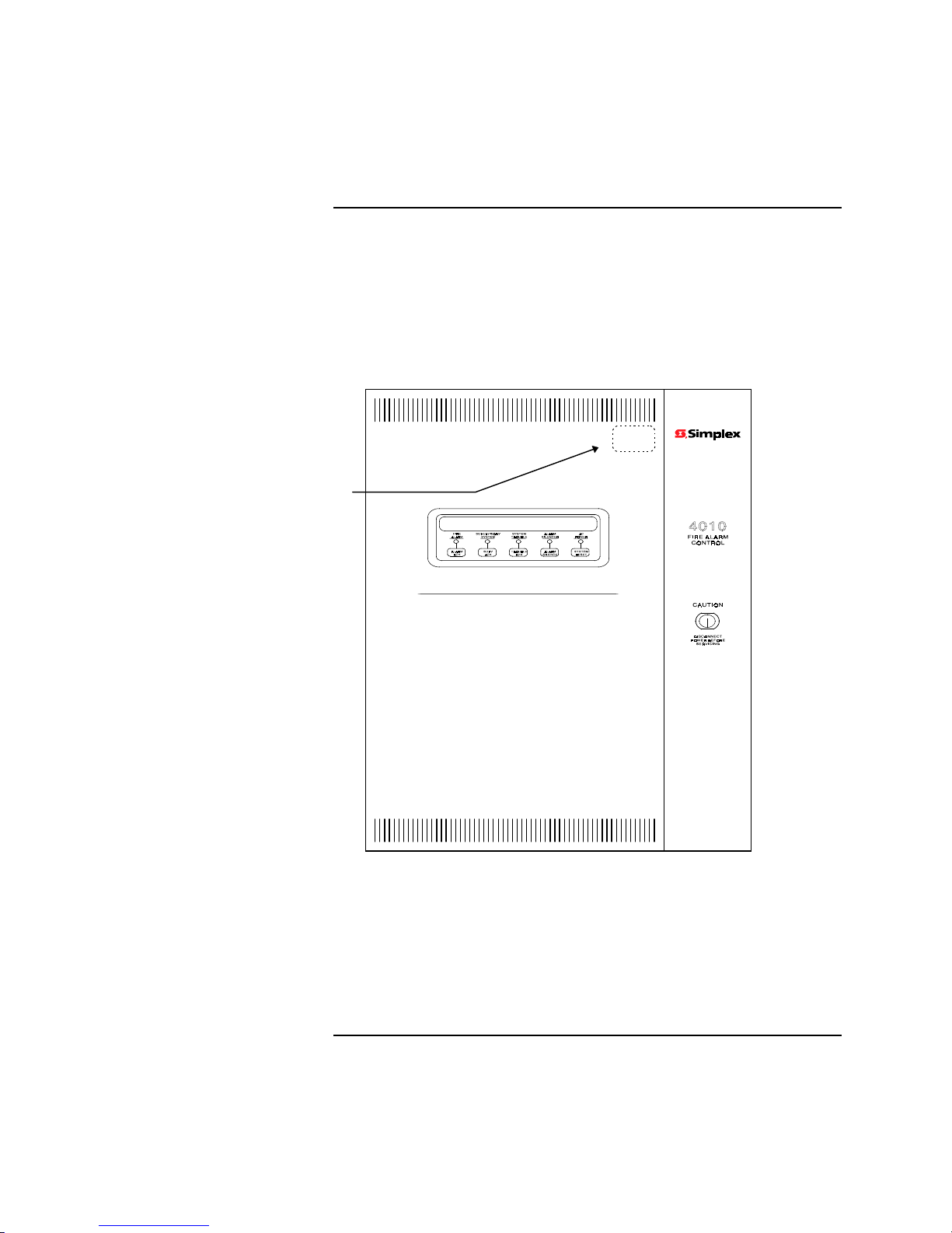
When an RS232 card is installed in the 4010 Fire Alarm Control Panel, the panel
must be labeled to indicate this fact. The label informs all persons servicing the
system that the panel is configured with an RS232 card and complies with FCC
Part 68 (Part No. 519-749) and Industry Canada (519-751) listings. To apply
the label, do the following:
1. Refer to Figure 1 and locate the LCD Display and the Touch Pad keys
below it.
Figure 1. Placement for FCC Part 68 and Industry Canada Labels
2. Notice the placement of the labels above and to the right of the LCD
Display and the Touch Pad keys in Figure 1.
3. Place the FCC and Industry Canada labels on the 4010 Fire Alarm Control
Panel door in the same position as that shown in Figure 1. Be sure not to
cover vent holes.
Technical Manuals Online! - http://www.tech-man.com
4
Page 5

4010-9811 Dual RS232 Card
Overview
The 4010-9811 Dual RS232 Card (Part No. 565-810) is connected to the N2
communication lines. The 4010 can vector messages to RS232 ports by
category. The RS232 ports may be configured as follows:
x
Two serial printers (80 or 40 col u mn).
x
One serial printer and one CRT/Keyboard (command line interface).
The RS232 ports on the option card are elect rical l y isolated from earth , all owing
connection of an AC powered printer or CRT/keyboard with ou t cau s i n g a power
supply Earth Fa u lt trouble at the FACP.
Figure 2 shows the location of connectors and switches.
Serial Port A (P7)
Serial Port B (P6)
Reset Switch (SW3)
Baud Rate Selection (SW2)
Address Switch (SW1)
N2 Interface (P2)
N2 Interface (P1)
565-810
ASSEMBLY
Figure 2. 4010-9811 Dual RS232 Card
Technical Manuals Online! - http://www.tech-man.com
5
Page 6

4010-9812 RS232/Service Modem Card
Overview
The 4010-9812 RS232/Service Modem Card (Part No. 565-811) is similar to the
dual RS232 card except that one port is a dedicated Service Modem port
(command line interface). The second port (Port A) may be programmed for use
with a serial printer or left unused. Event vectoring by category is supported on
the modem and RS232 ports.
The RS232 port (Port A) on the opt ion card i s elect rical ly isolated from earth ,
allowing connection of an AC powered printer without causing a power supply
Earth Fault trouble at the FACP.
Figure 3 shows the location of connectors and switches.
RJ-11 Telco Jacks (P8-P10)
P8 P9 P10
P7
Serial Port A (P7)
Reset Switch (SW3)
Baud Rate Selection (SW2)
Address Switch (SW1)
N2 Interface (P2)
N2 Interface (P1)
Figure 3. 4010-9812 RS232/Service Modem Card
565-811
ASSEMBLY
Technical Manuals Online! - http://www.tech-man.com
6
Page 7

Configuration
Switch Settings
Card Address Setting (SW1)
Option cards in the 4010 system have specific addresses. The card address
setting for both the Dual RS232 and RS232/Service Modem cards is Card 4. Set
SW1-3 to the ON position and set the remaining dip switches to the OFF
position.
Use the “Quick CFIG - Add NEW Hardware” function described in the 4010
Fire Alarm - Installation/Operation Instructions (574-052) to add the card to the
system.
Baud Rate Setting (SW2)
N2 Communications on option cards must be set at the same baud rate as the
4010 FACP. Both the Dual RS232 and RS232/Service Modem card’s baud rates
are set from SW2. Use the information in Table 1 to set SW2 to the appropriate
baud rate. The default setting should be 9600.
Table 1. Baud Rate Settings
Baud Rate SW2-1 SW2-2
OFF-Line ON ON
9600 OFF ON
19200 ON OFF
38400 OFF OFF
Technical Manuals Online! - http://www.tech-man.com
7
Page 8

Wiring
4010-9811 Dual RS232 Card
This section describes the wire terminations for Port A (P7) and Port B (P6) on
the Dual RS232 card. Refer to the “Card Installation” section of this publication
for information on connecting the card to the FACP.
Remove the terminal block before attaching wires from the RS232 cable. Once
the wires are attached, reconnect the terminal block after the card is installed.
Use Figure 4 and Tables 2 and 3 to wire Port A and/or Port B.
Table 2. Wiring Distance Table 3. RS232 Pin Connections
Baud
Rate
Max. Wiring
Distance
Signal From
P6 or
To DB-25
Pin
To DB-9
Pin
P7 Pin
1200 1300 ft TXD 1 3 2
2400 800 ft RXD 2 2 3
4800 500 ft RTN 3 7 5
9600 300 ft RTS 4 5 8
19200 300 ft CTS 5 4 7
38400 300 ft Shield 6 - -
Notes:
1. Port A is dedicated for use with a
printer. Port B is dedicated for
use with a CRT/keyboard.
2. The RS232 ports are isolated
from the 4010 power supply.
Ground fault supervision is
performed by the card itself.
TXD 1
RXD 2
RTN 3
RTS 4
CTS 5
SHIELD 6
Technical Manuals Online! - http://www.tech-man.com
Figure 4. RS232 Wiring
Continued on next page
8
Page 9

Wiring,
p
Continued
4010-9812 RS232/Service
Modem Card
This section describes the wire terminations for Port A (P7) and the Telco RJ-11
jacks (P8 through P10) on the RS232/Service Modem card. Refer to the “Card
Installation” section of this publication for information on connecting the card to
the FACP.
Remove the terminal block before attaching wires from the RS232 cable. Once
the wires are attached, reconnect the terminal block after the card is installed.
Use Figure 3 and Tables 2 and 3 to wire Port A.
Use Figure 5 to connect the RJ-11 jacks to connectors P8 through P10.
Notes:
1. Telco line interface is analog, 2-wire, with a UL-Listed RJ-11
jack.
2. The Telco lines should be connected to the RS232/Service
Modem card as follows:
A. If a single line is available and service phone is desired,
connect to the secondary line (P9) and connect a
telephone to the service phone line (P8). This
configuration permits voice calls on the service phone
while the modem is NOT in use. Otherwise, connect to
the primary line (P10).
B. If two lines are available, connect one to the primary
line (P10) and the other to the secondary line (P9).
Connect a telephone to the service phone line (P8).
This configuration permits simultaneous use of the
service phone on the secondary line and the service
modem on the
rimary line.
SERVICE
PHONE
SECONDARY
TELCO LINE
PRIMARY
TELCO LINE
P8 P9 P10
2
1
Figure 5. RJ-11 Telco Line Connections
Technical Manuals Online! - http://www.tech-man.com
9
Page 10

Card Installation
Mounting
Install a single option card in Expansion Slot 2 shown in Figure 6. When an
option card is already present, install the additional option card in Expansion
Slot 1. Each option card comes with all necessary harnesses and mounting
hardware. Use Steps 1 through 5 to install either card into the 4010 FACP.
1. Disconnect battery and then AC power from the FACP.
2. Set all appropriate dip switch settings and terminate all wiring to their
appropriate connectors.
3. Slide the option card into the appropriate expansion slot (see Figure 6).
Expansion Slot 1
Expansion Slot 2
Figure 6. Option Card Expansion Slots
Technical Manuals Online! - http://www.tech-man.com
Continued on next page
10
Page 11

Card Installation,
Continued
Mounting
(continued)
4. Using the screw and lockwasher provided, secure the mounting bracket to
the system chassis (see Figure 7).
Mounting Bracket at the top
of the Option Card
Mounting Hole
Figure 7. Option Card Mounting Bracket
5. Slide the card lock bracket into the bottom hole in the option card. Secure
the bottom of the option card by tightening the card lock bracket screw (see
Figure 8).
Option Card
Card Lock Bracket
Technical Manuals Online! - http://www.tech-man.com
Figure 8. Card Lock Bracket
Continued on next page
11
Page 12

Card Installation,
Continued
N2 Communications/Power
Connections
Each option card comes with two N2 Communications/Power Harnesses; the
733-953 is a long harness used to interface the option card with the FACP, the
733-956 is a short harness used to “daisy-chain” one option card to another.
Use Steps 1 through 4 to connect the N2 Communications from the option card
to the FACP.
1. Remove battery and then AC power from the FACP.
2. Verify that all switches are set correctly.
3. Using the 733-953 harness, connect one end from P1 of the option card to
P1 of the 4010 FACP. P1 on the FACP is located between TB2 and TB3.
IMPORTANT: Pay careful attention to the routing for Power-
Limited and Non-Power Limited wiring. You must
maintain a 1/4-inch separation between these two
types of wiring. Neatly dress all harnesses and
wiring.
4. If another option card is installed that is already connected to the FACP, use
the 733-956 harness to connect P2 of one option card to P2 of the other. You
can now apply AC and then battery power.
Technical Manuals Online! - http://www.tech-man.com
574-058
Rev. B
 Loading...