

Page 1

4010 Fire Alarm
F
Front Panel Installing, Operating, and
Programming Instructions
574-052
Rev.
Technical Manuals Online! - http://www.tech-man.com
Page 2

This page intentionally blank
Technical Manuals Online! - http://www.tech-man.com
Page 3

Copyright and Trademarks
Cautions and Warnings
Copyright Simplex Time Recorder Co., 2000. All rights reserved.
Printed in the United States of America.
Information in this document is subject to change without notice. No part of this
document may be reproduced or transmitted in any form or by any means,
electronic or mechanical, for any purpose, without the express written consent of
Simplex Time Recorder Company.
Walk Test is protected by US Patent No. 4,725,818.
MAPNET addressable communications is protected by US Patent No.4,796,025.
IDNet is patent pending.
TrueAlarm Analog Detection is protected by US Patent No. 5,155,468.
TrueAlarm Detector Base is protected by US Patent No. 5,173, 683.
SYSTEM REACCEPTANCE TEST AFTER SOFTWARE CHANGES - To
ensure proper system operation, this product must be tested in accordance with
NFPA72-1996, Chapter 7 after any programming operation or change in sitespecific software. Reacceptance testing is required after any change, addition or
deletion of system components, or after any modification, repair or adjustment to
system hardware or wiring.
All components, circuits, system operations, or software functions known to be
affected by a change must be 100% tested. In addition, to ensure that other
operations are not inadvertently affected, at least 10% of initiating devices that
are not directly affected by the change, up to a maximum of 50 devices, must
also be tested and proper system operation verified.
READ AND SAVE THESE INSTRUCTIONS. Follow the instructions in the
installation, operating and programming manuals. These instructions must be
followed to avoid damage to the control panel and associated equipment. Fire
Alarm Control Panel (FACP) operation and reliability depend upon proper
installation.
DO NOT INSTALL ANY SIMPLEX PRODUCT THAT APPEARS
DAMAGED. Upon unpacking your Simplex product, inspect the contents of the
carton for shipping damage. If damage is apparent, immediately file a claim
with the carrier and notify Simplex.
ELECTRICAL HAZARD - Disconnect electrical power when making any
internal adjustments or repairs. Servicing should be performed by qualified
Simplex Representatives.
RADIO FREQUENCY ENERGY - This equipment generates, uses, and can
radiate radio frequency energy and if not installed and used in accordance with
the instruction manual, may cause interference to radio communications. It has
been tested and found to comply with the limits for a Class A computing device
pursuant to Subpart J of Part 15 of FCC Rules, which are designed to provide
reasonable protection against such interference when operated in a commercial
environment. Operation of this equipment in a residential area may cause
interference in which case the user at his own expense will be required to take
whatever measures may be required to correct the interference.
Technical Manuals Online! - http://www.tech-man.com
i
Page 4

This page intentionally blank.
Technical Manuals Online! - http://www.tech-man.com
ii
Page 5

Codes and Standards
The 4010 is listed for the following listing categories.
UL 864 Listings for Type of System:
• UL 864 Power-Limited Fire Alarm Control Unit
• Local (formerly NFPA 72A)
Requires the sounding of an alarm via listed notification appliance(s)
• Auxiliary (formerly NFPA 72B)
Requires 4010-9809 City Circuit Module
• Remote Station - protected premise (formerly NFPA 72C)
Requires 4010-9809 City Circuit Module or the 4010-9810 or -9816 DACT
• Proprietary - protected premise (formerly NFPA 72D)
Requires 4010-9817 (with 4010-9818 or 4010-9819) or 4010-9821 Network
Interface Modules
• Central Station - protected premise (formerly NFPA 71)
Requires 4010-9810 or -9816 DACT
• Suppression Releasing Service
Requires 4010-9814 Suppression Kit
UL 864 Listings for Type of Service:
• Automatic, Manual, Waterflow, and Sprinkler Supervisory
UL 864 Listings for Type of Signaling:
• Coded, Non-Coded, March-Time and DACT
Requires the 4010-9810 or -9816 DACT
Factory Mutual Approved:
• Same as UL above
Local Approvals:
• CSFM*
• MEA
• City of Chicago (pending)
*This product has been approved by the California State Fire Marshal (CSFM) pursuant to Section 13144.1 of the California Health
and Safety Code. See CSFM Listing No. 7170-0026:226
presented in this document.
for allowable values and/or conditions for use concerning material
iii
Technical Manuals Online! - http://www.tech-man.com
Page 6

Codes and Standards
(continued)
The installer should be familiar with the relevant codes listed below as well as
any other applicable local codes and standards, when installing a fire alarm
system.
• NFPA 72 National Fire Alarm Code
• NFPA 11 Standard for Low-Expansion Foam and Combined Agent
Systems
• NFPA 11A Standard for Medium- and High-Expansion Foam Systems
• NFPA 12 Standard on Carbon Dioxide Extinguishing Systems
• NFPA 12A Standard on Halon 1301 Fire Extinguishing Systems
• NFPA 13 Standard for the Installation of Sprinkler Systems
• NFPA 14 Standard for the Installation of Standpipe and Hose Systems
• NFPA 15 Standard for Water Spray Fixed Systems for Fire Protection
• NFPA 16 Standard for the Installation of Deluge Foam-Water Sprinkler
and Foam-Water Spray Systems
• NFPA 16A Standard for the Installation of Closed-Head Foam-Water
Sprinkler Systems
• NFPA 17 St andard for Dry Chemical Extinguishing Systems
• NFPA 17A Standard for Wet Chemical Extinguishing Systems
• NFPA 25 Standard for Inspection, Te sting, and Maintenance of
Water-Based Fire Protection Systems
• NFPA 70 National Electrical Code
• NFPA 80 Standard for Fire Doors and Fire Windows
• NFPA 90A Standard for the Installation of Air Conditioning and
Ventilation Systems
• NFPA 90B Standard for the Installation of Warm Air Heating and Air
Conditioning Systems
• NFPA 92A Recommended Practice for Smoke-Control Systems
• NFPA 92B Guide for Smoke Management Systems in Malls, Atria, and
Large Areas
• NFPA 101 Life Safety Code
• NFPA 170 Standard for Fire Safety Symbols
• NFPA 231C Standard for Rack Storage of Materials
• NFPA 1221 Standard on the Installation, Maintenance, and Use of Public
Fire Service Communication Systems
About this Manual
The following conventions are used in this publication to identify special names
or text.
• When a membrane panel key (located below the display) is referenced in
this manual, it is normally shown between left and right arrows. Examples
are <ALARM SILENCE> and <SYSTEM RESET>.
• Text enclosed in quotation marks indicates the title of a chapter or section of
the manual, such as "About this Manual."
• Bulleted lists, such as this one, provide you with information. They are also
used to indicate alternatives in numbered procedural steps.
• Numbered lists indicate procedures with steps that you must carry out
sequentially.
Technical Manuals Online! - http://www.tech-man.com
iv
Page 7

Table of Contents
Chapter 1. 4010 FACP Overview
Introduction...............................................................................................1-1
In this Chapter...........................................................................................1-1
Related Documentation.................................................................................1-2
Base System Module..................................................................................... 1-3
Overview...................................................................................................1-3
SFI/O.........................................................................................................1-3
Power Supply – Base System.................................................................... 1-4
Default Settings.........................................................................................1-4
Environmental Specifications ................................................................... 1-4
Optional System Modules............................................................................. 1-5
Overview...................................................................................................1-5
Optional Modules with Dedicated Hardware Slots................................... 1-5
Optional Modules for Expansion Slots..................................................... 1-6
Remote Optional Modules........................................................................ 1-7
Other Compatible Equipment....................................................................1-8
User Interface................................................................................................1-9
Overview...................................................................................................1-9
Operator Key Definitions..........................................................................1-9
Menu Navigation Key Definitions..........................................................1-10
Passcodes, Access Levels, and Logging In and Out....................................1-12
Overview.................................................................................................1-12
Passcodes and Access Levels.................................................................. 1-12
Logging In and Out................................................................................. 1-13
Menu Structure............................................................................................1-14
Chapter 2. Back Box Installation
Overview...................................................................................................2-1
In this Chapter...........................................................................................2-1
Before You Begin......................................................................................... 2-2
Unpacking the System...............................................................................2-2
Installation Guidelines..............................................................................2-2
Standards and Codes.................................................................................2-2
Remove Chassis and Cut Conduit Openings.................................................2-3
Overview...................................................................................................2-3
Step 1. Remove the Chassis.....................................................................2-3
Step 2. Cut Conduit Entrances................................................................. 2-3
Mount the Backbox.......................................................................................2-4
Surface Mounting the Back Box...............................................................2-4
Semi-Flush Mounting the Back Box.........................................................2-4
Re-install the Chassis.................................................................................... 2-5
Procedure.................................................................................................. 2-5
Technical Manuals Online! - http://www.tech-man.com
v
Page 8

Chapter 3. Wiring
Overview...................................................................................................3-1
In this Chapter...........................................................................................3-1
Overview.......................................................................................................3-2
Power Limited Versus Non-Power Limited Systems................................3-2
Locations of Terminal Connections..........................................................3-3
NAC Wiring..................................................................................................3-4
Overview...................................................................................................3-4
Terminal Connections...............................................................................3-4
IDNet Wiring................................................................................................ 3-5
Overview...................................................................................................3-5
Terminal Connections...............................................................................3-5
AC Power and Battery Wiring...................................................................... 3-6
AC Power..................................................................................................3-6
Installing and Connecting Batteries .......................................................... 3-7
Auxiliary Relays............................................................................................3-9
Auxiliary Relays........................................................................................3-9
System Power-Up and Checkout.................................................................3-10
Connect AC & Battery Power.................................................................3-10
Power-Up and Checkout.........................................................................3-10
Acceptance Test......................................................................................3-12
Periodic Testing and Maintenance.............................................................. 3-13
Overview.................................................................................................3-13
Battery Testing Information....................................................................3-13
Chapter 4. Quick CFIG
Overview...................................................................................................4-1
Cautions and Warnings.............................................................................4-1
In this Chapter...........................................................................................4-1
Reconfigure ALL Hardware..........................................................................4-2
Overview...................................................................................................4-2
Procedure.................................................................................................. 4-2
Auto Detect NEW Hardware........................................................................4-3
Overview...................................................................................................4-3
Procedure.................................................................................................. 4-3
Restore Factory CFIG...................................................................................4-4
Overview...................................................................................................4-4
Procedure.................................................................................................. 4-4
Accept Default Settings for System Options................................................. 4-5
Procedure.................................................................................................. 4-5
Edit Settings for System Options..................................................................4-6
Overview...................................................................................................4-6
Procedure.................................................................................................. 4-6
Save CFIG Option.........................................................................................4-8
Overview...................................................................................................4-8
Technical Manuals Online! - http://www.tech-man.com
vi
Page 9

Chapter 5. Configuring Cards
Overview...................................................................................................5-1
In this Chapter...........................................................................................5-1
Card Addresses............................................................................................. 5-2
Card Addresses.........................................................................................5-2
Adding, Deleting, or Modifying 4010 Cards ................................................ 5-3
Overview...................................................................................................5-3
Adding a Card...........................................................................................5-3
Deleting a Card.........................................................................................5-4
Modifying a Card...................................................................................... 5-5
Chapter 6. Configuring Points
Overview...................................................................................................6-1
In this Chapter...........................................................................................6-1
Configure Points Menu.................................................................................6-2
Configuring Points Menu..........................................................................6-2
Configuring TrueAlarm Points......................................................................6-3
Overview...................................................................................................6-3
Add IDNet Point....................................................................................... 6-3
Edit TrueAlarm Point................................................................................6-3
Delete TrueAlarm Point............................................................................6-4
Configuring ZAM/IAM/RIAM Points.......................................................... 6-6
Overview...................................................................................................6-6
Adding ZAM/IAM/RIAM Point............................................................... 6-6
Editing a ZAM/IAM/RIAM Point.............................................................6-6
Deleting ZAM/IAM/RIAM IDNet Point...................................................6-8
Configuring Relay and NAC Points.............................................................. 6-9
Overview...................................................................................................6-9
Procedure.................................................................................................. 6-9
Configuring Digital and Analog Pseudo Points..........................................6-11
Overview.................................................................................................6-11
Configuring Digital Pseudo Points.......................................................... 6-11
Configuring Analog Pseudo Points......................................................... 6-12
Configuring 24-Point I/O Points.................................................................6-14
Overview.................................................................................................6-14
Configuring 24-Point Input Points.......................................................... 6-14
Configuring 24-Point Output Points........................................................6-16
Configuring List Points...............................................................................6-18
Overview.................................................................................................6-18
Configure a List......................................................................................6-18
Add a Point to a List...............................................................................6-19
Delete a Point from a List....................................................................... 6-19
Delete ALL Points from a List................................................................6-20
Configuring User-Defined SW/LED........................................................... 6-21
Overview.................................................................................................6-21
Configure a User-Defined Switch or LED.............................................. 6-21
Edit a Mode of a User-Defined SW/LED............................................... 6-22
Technical Manuals Online! - http://www.tech-man.com
vii
Page 10

Chapter 7. System Options
Overview...................................................................................................7-1
In this Chapter...........................................................................................7-1
System Options Menu................................................................................... 7-2
Introduction...............................................................................................7-2
Time/Date Format......................................................................................... 7-3
Overview...................................................................................................7-3
Setting the Time Format............................................................................7-3
Active Status Reminder.................................................................................7-4
Overview...................................................................................................7-4
Setting the Active Status Reminder...........................................................7-4
Silence/Reset Inhibit..................................................................................... 7-5
Overview...................................................................................................7-5
Setting the Silence/Reset Inhibit ............................................................... 7-5
Alarm Cut-Out Timer....................................................................................7-6
Overview...................................................................................................7-6
Setting the Alarm Cut-Out Timer..............................................................7-6
Door Drop on Alarm..................................................................................... 7-7
Overview...................................................................................................7-7
Setting the Door Drop on Alarm Timer....................................................7-7
Door Drop on AC Loss................................................................................. 7-8
Overview...................................................................................................7-8
Setting the Door Drop on AC Loss Timer ................................................ 7-8
Audible and Visible NAC Operation............................................................7-9
Overview...................................................................................................7-9
Setting the Audible or Visual NAC Operation.......................................... 7-9
TrueAlert Non-Addressable Horn Operation..............................................7-10
Introduction.............................................................................................7-10
Setting the TrueAlert Non-Addressable Horn Option............................. 7-10
Depleted Battery Cut-Out...........................................................................7-11
Overview.................................................................................................7-11
Setting the Depleted Battery Cut-Out .....................................................7-11
Stagger Start AHUs.....................................................................................7-12
Overview.................................................................................................7-12
Setting the Stagger Start AHU Delay Timer...........................................7-12
Enable City Circuit......................................................................................7-13
Overview.................................................................................................7-13
Setting the Enable City Circuit Option....................................................7-13
Expansion Power........................................................................................7-14
Overview.................................................................................................7-14
Setting the Expansion Power Option.......................................................7-14
Single-Station..............................................................................................7-15
Overview.................................................................................................7-15
Enabling Single-Station..........................................................................7-15
Technical Manuals Online! - http://www.tech-man.com
viii
Page 11

Suppression Release....................................................................................7-16
Overview.................................................................................................7-16
Example..................................................................................................7-16
Step 1. Turn ON Suppression Release...................................................7-17
Step 2. Assign Suppression Monitor Point Types to Suppression
Release Monitor Points..............................................................7-17
Step 3. Create Suppression Release Monitor Lists.................................7-17
Step 4. Assign Point Types to Suppression Outputs..............................7-18
Step 5. Create Suppression Release Output Lists...................................7-18
Chapter 8. Custom Control
Introduction...............................................................................................8-1
In this Chapter...........................................................................................8-1
Overview.......................................................................................................8-2
Introduction...............................................................................................8-2
SMPL Opcodes and Operators......................................................................8-3
Input Opcodes...........................................................................................8-3
Input and Relational Operators................................................................. 8-4
Output Opcodes ........................................................................................ 8-5
Custom Control Equation..............................................................................8-6
Custom Control Example..........................................................................8-6
Custom Control Programming...................................................................... 8-7
To Start Custom Control Programming....................................................8-7
Custom Control Menu Navigation............................................................ 8-8
Equation Level..........................................................................................8-9
Custom Control Level...............................................................................8-9
Equations ................................................................................................ 8-10
Input Side (IF).........................................................................................8-10
Field 1.....................................................................................................8-10
Field 2.....................................................................................................8-15
Fields 3 & 4.............................................................................................8-16
Output Side (THEN)...............................................................................8-24
Application-Specific Examples................................................................... 8-26
Introduction.............................................................................................8-26
Day Night Programming Example..........................................................8-26
TrueAlarm Heat Utility Monitoring Example.........................................8-26
City Circuit Alarm-Output Programming Example................................. 8-26
AHJ City Circuit Reset Operation Example............................................8-27
Chapter 9. Saving a CFIG
Introduction...............................................................................................9-1
In this Chapter...........................................................................................9-1
Viewing CFIG Properties..............................................................................9-2
Introduction...............................................................................................9-2
Procedure.................................................................................................. 9-2
Continue, Restore CFIG, and Save CFIG.....................................................9-3
Continue.................................................................................................... 9-3
Restore CFIG............................................................................................ 9-3
Save CFIG.................................................................................................9-3
Technical Manuals Online! - http://www.tech-man.com
ix
Page 12

Chapter 10. Diagnostics and Troubleshooting
Overview.................................................................................................10-1
Before Calling Tech Support.................................................................. 10-1
Diagnostics..................................................................................................10-2
Overview.................................................................................................10-2
Running Diagnostics...............................................................................10-2
Diagnostic Options..................................................................................10-3
N2 Comm Diagnostics............................................................................10-3
IDNet Diagnostics...................................................................................10-3
IDNet Earth Fault Search Diagnostics.................................................... 10-4
Network Diagnostics...............................................................................10-4
Walk Test.................................................................................................... 10-6
Overview.................................................................................................10-6
Using Walk Test ..................................................................................... 10-6
TrueTest......................................................................................................10-8
Overview.................................................................................................10-8
Using TrueTest ....................................................................................... 10-9
Crash Codes.............................................................................................. 10-10
Chapter 11. Operation
Overview.................................................................................................11-1
In this Chapter.........................................................................................11-1
Handling Abnormal Conditions..................................................................11-2
Normal Operation...................................................................................11-2
Abnormal Conditions.............................................................................. 11-2
Acknowledging an Alarm, Trouble, or Supervisory Condition...............11-3
Silencing Alarms.....................................................................................11-3
Resetting the System............................................................................... 11-4
Viewing and Clearing Historical Logs........................................................ 11-5
Overview.................................................................................................11-5
Using the Historical Logs........................................................................11-6
Viewing and Controlling Points..................................................................11-7
Overview.................................................................................................11-7
Controlling/Viewing Points.....................................................................11-7
How to Disable/Enable Points ................................................................ 11-9
How to Disable Points in Alarm.............................................................11-9
Editing Custom Labels.............................................................................. 11-10
How to Edit a Custom Label.................................................................11-10
User Control Functions.............................................................................11-12
Overview...............................................................................................11-12
Using the Function Options...................................................................11-12
Setting the Time and Date.........................................................................11-14
Technical Manuals Online! - http://www.tech-man.com
x
Page 13

Appendix A. Device and Point Types
Overview.................................................................................................. A-1
In this Chapter.......................................................................................... A-1
Hardware Device Types............................................................................... A-2
Overview.................................................................................................. A-2
TrueAlarm Hardware Device Types........................................................ A-2
TrueAlarm Levels and Sensitivities......................................................... A-3
Monitor Hardware Device Types............................................................. A-3
4009A Hardware Device Types............................................................... A-4
Software Point Types................................................................................... A-5
Monitor Point Types................................................................................ A-5
Signal Point Types................................................................................... A-6
Relay Point Types.................................................................................... A-7
TrueAlert Point Types.............................................................................. A-8
Appendix B. Hardware and Pseudo Points
Overview.................................................................................................. B-1
In this Chapter.......................................................................................... B-1
Hardware Points........................................................................................... B-2
Introduction.............................................................................................. B-2
General Card Status Point Information.................................................... B-2
Master Controller Card............................................................................ B-2
Master Controller Card Status Points....................................................... B-2
Master Controller Points.......................................................................... B-2
NAC Card................................................................................................ B-3
NAC Card Status Points........................................................................... B-3
NAC Card Points..................................................................................... B-4
Power Supply Card.................................................................................. B-5
Power Supply Card Status Points............................................................. B-5
Power Supply Points................................................................................ B-5
IDNet Card............................................................................................... B-6
IDNet Card Status Points......................................................................... B-6
IDNet Points ............................................................................................ B-7
RS232/Modem Card................................................................................ B-8
RS232/Modem Card Status Points........................................................... B-8
RS232/Modem Points.............................................................................. B-8
DACT Card.............................................................................................. B-9
DACT Card Status Points........................................................................ B-9
SDACT Points ......................................................................................... B-9
Network Card......................................................................................... B-10
Network Card Status Points................................................................... B-10
Network Points....................................................................................... B-10
24I/O Card............................................................................................. B-11
24I/O Card Status Points........................................................................ B-11
24I/O Points........................................................................................... B-12
LCD Card............................................................................................... B-12
LCD Card Status Points......................................................................... B-12
LCD Points ............................................................................................ B-13
Pseudo Points............................................................................................. B-14
Introduction............................................................................................ B-14
Digital Pseudo Points............................................................................. B-14
4010 System Digital Pseudos................................................................. B-15
Technical Manuals Online! - http://www.tech-man.com
xi
Page 14

4010 User Digital Pseudos..................................................................... B-17
Analog Pseudo Points............................................................................ B-18
4010 System Analog Pseudos................................................................ B-18
4010 User Analog Pseudos.................................................................... B-18
List Pseudo Points.................................................................................. B-19
4010 System Lists.................................................................................. B-19
4010 User Lists...................................................................................... B-20
Appendix C. Glossary of Terms
Overview...................................................................................................C-1
Glossary....................................................................................................C-1
Index ............................................................................... IN-1
Technical Manuals Online! - http://www.tech-man.com
xii
Page 15

Chapter 1
4010 FACP Overview
Overview
Introduction
In this Chapter
The 4010 is a single-channel, addressable, modular Fire Alarm Control Panel
(FACP) that monitors and controls up to 250 IDNet addressable devices. The
Standard Function Input/Output (SFI/O) card, power supply, and cabinet provide
a complete fire alarm control panel for most applications. Optional modules
mount to the chassis to provide additional inputs and outputs, network
communication, and additional power. Additionally, the 4010 can automatically
control supplementary equipment such as fire doors and fans during an alarm
condition using its auxiliary relay outputs.
The 4010 provides audible and visible indications during trouble, supervisory, or
alarm (fire) conditions. Should any of these conditions occur, the system
activates the applicable notification appliance(s), LEDs, and the panel tone-alert.
The indications continue until someone appropriately acknowledges the
condition.
This publication describes how to install, configure, operate, program, and test
the Simplex 4010 Fire Alarm Control Panel (FACP).
This chapter discusses the following topics:
Topic See Page #
Related Documentation 1-2
Base System Module 1-3
Optional System Modules 1-5
User Interface 1-9
Passcodes, Access Levels, and Logging In and Out 1-12
Menu Structure 1-14
Technical Manuals Online! - http://www.tech-man.com
1-1
Page 16

Related Documentation
The following table lists publications that provide specific information
concerning field wiring, replacement parts, optional modules, and application
information.
Publication Title Part Number
4010-9806 Class A Module - Installation Instructions 574-055
4010-9809 City Circuit Card - Installation Instructions 574-056
4010 Fire Alarm Expansion Power Supplies Installation
Instructions
4010 Fire Alarm RS232 Interface and Service Modem Cards
Installation Instructions
4010-9820 Battery Meter Module - Installation Instructions 574-165
4010-9814 Suppression Kit - Installation Instructions 574-166
4010 Fire Alarm DACT Modules - Installation Instructions 574-167
4010 Fire Alarm 4120 Network Interface Cards Installation
Instructions
4010 Fire Alarm - Parts List 574-424
4098 Detectors, Sensors, and Bases - Application Manual 574-709
4010 Fire Alarm - Field Wiring Diagrams 842-058
574-057
574-058
574-168
Technical Manuals Online! - http://www.tech-man.com
1-2
Page 17
Base System Module
Overview
Overview
SFI/O
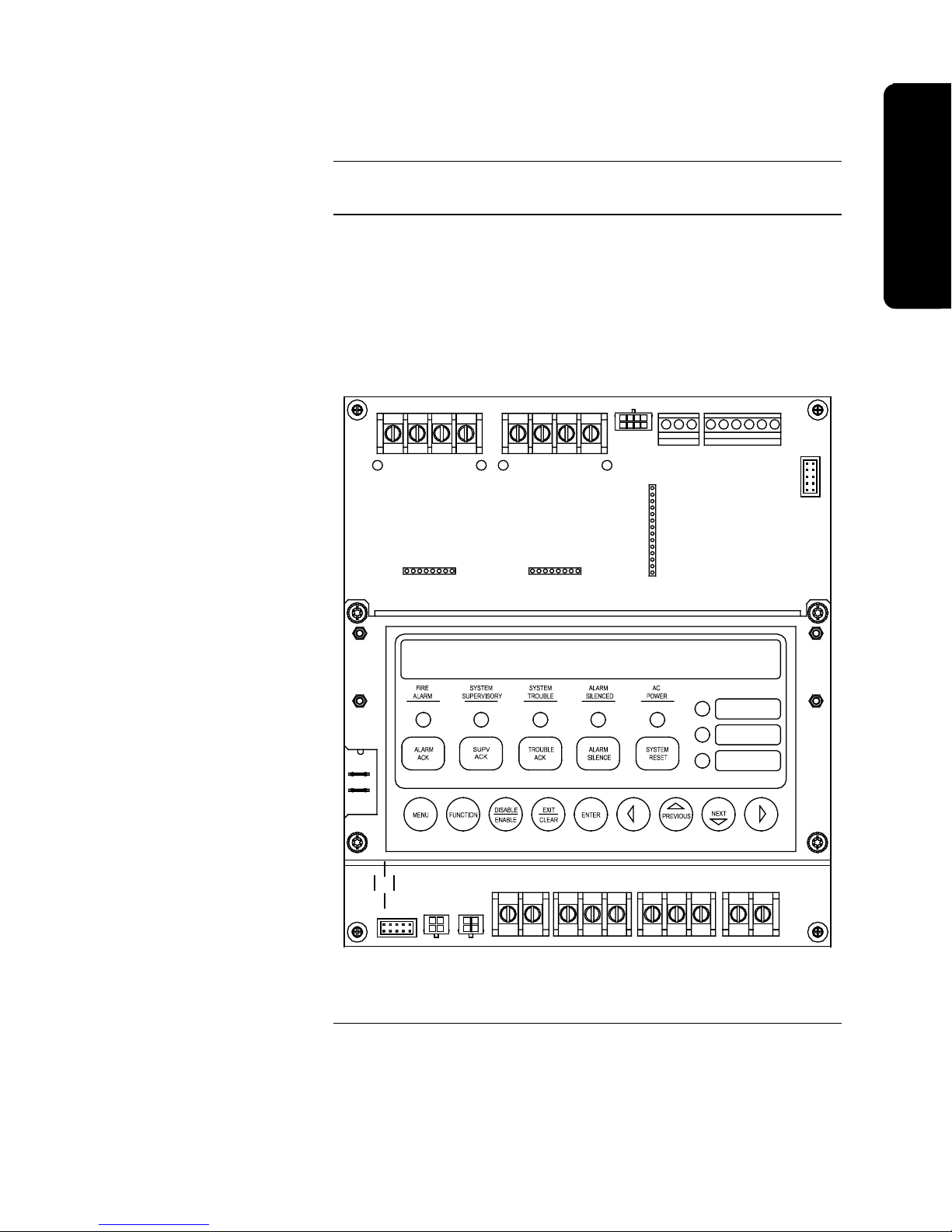
The 4010 Base System includes the SFI/O card, power supply, and cabinet.
The SFI/O contains all connections for optional modules as well as N2
annunciator communication, IDNet, NAC, Auxiliary Power, Auxiliary Relay, PC
Programmer (service port), and expansion power connections.
The User Interface provides a 2x40 LCD screen, LEDs, operational and
programming keys, all of which are visible with the cabinet door closed. See
“User Interface,” later in this chapter for additional information about the user
interface.
TB1
TB2
TB3 TB4
Technical Manuals Online! - http://www.tech-man.com
TB6 TB7
P13
P14
Figure 1-1. 4010 SFI/O with User Interface
Continued on next page
1-3
TB8TB5
Page 18

Base System Module, Continued
Power Supply – Base System
Default Settings
Base System:
• 120VAC +10% / -15%, 60Hz or 220/240VAC +10% / -15%, 50/60Hz
• 24VDC (unregulated) 4A alarm power
• 24VDC, 1/2 Amp auxiliary power
• Battery Charger for 25Ah Batteries, 24-hour recharge at 120VAC (for larger
battery capacity, use the 4081-9301, -9302, -9303, or -9304 External
Battery Cabinet w/Charger)
Note: The 4010 back box can accommodate up to 25Ah batteries.
All switches and potenti ometers are set at t he factory before shipping. Although
the settings should be accurate, you can change the settings on the following
components as indicated.
• LCD Adjustment (R143) – If necessary, use a small flat head screwdriver,
turn the R143 Potentiometer located below TB1 to adjust the contrast on the
LCD for the 4010.
• Baud Rate Setting (SW2) - Baud rate settings for the 4010 communications
are shown in Table 1-1 below. If you receive a communications trouble at
the panel, verify that SW2 is set correctly.
Table 1-1. SW2 Switch Settings
Baud Rate SW2-1 SW2-2
OFF LINE ON ON
9,600 OFF ON
19,200 ON OFF
19,200 OFF OFF
Important: You must set all cards to the same baud rate in order for the
4010 to operate properly. If you have a 4010 with a Network or DACT
card, you must set the SW2 dip switch to the 9600 baud rate. It is
recommended that you use the 19,200 option when uploading/downloading
information to a PC.
Environmental Specifications
Temperature:
The 4010 operates normally with ambient temperatures from 32° F to 120° F
(0°C to 49°C), inclusive.
Humidity:
The 4010 operates normally under non-condensing humidity conditions up to
85% relative humidity @ 86° F (30°C).
Technical Manuals Online! - http://www.tech-man.com
1-4
Page 19

Optional System Modules
Overview
Overview
Optional Modules with
Dedicated Hardware Slots
The following is a list of optional modules for the 4010. Refer to the individual
instructions that accompany each module for more information. Those
instructions and their part numbers are listed in the “Related Documentation”
section of this chapter. Refer to the label inside the door of the 4010 for the
placement of optional modules.
Note: Certain modules are mutually exclusive. For example:
• One DACT or One City Circuit Card is allowed.
• One 4120 Network Card or One DACT is allowed.
• One Dual RS232 Card or One RS232/Modem is allowed.
• One Battery Meter Module or One 24VDC Extender Terminal
Block.
The 4010 has five dedicated mounting locations to support the following
modules.
4010-9806 Class A Adapter Card for NACs
The four NACs found on the SFI/O board are Class B (Style Y). To support
Class A (Style Z) you must install an adapter card that mounts to the SFI/O
board. Each adapter card supports two NACs.
4010-9809 City Circuit Card
The city circuit card conn ects to th e S F I/O with a ribbon harn es s to prov i de UL listed connections to either Remote Station (reverse polarity) or Public Service Fire
Communication s C en ter (local en erg y) receiving units (s electable). The card has
two circuits -- Ci rcu it 1 reports on ly alarm events an d Ci rcu it 2 can be configured
to report Trouble events or Trouble and Supervisory ev en ts. In th e ev en t of a C PU
failure, a city card configu red f or a Trouble Outpu t s ends a trou ble to th e city
circuit. The card is mounted to the righ t of th e SFI/O at th e top of th e ch ass is .
Newer versions of the 4010 FACP (Version 2.01 or later) provide the ability to
reset the City Circuit in the following situation.
• If the device(s) in alarm is physically removed.
• No other devices are in an alarm state.
• System Reset is performed.
Enabling City Circuit reset is done via Custom Control. Refer to “A pplication-
Specific Examples” at the en d of Chapter 8 for specific information. Be sure to
consult the AHJ before enabling the City Circuit Reset option.
Continued on next page
Technical Manuals Online! - http://www.tech-man.com
1-5
Page 20

Optional System Modules, Continued
Optional Modules with
Dedicated Hardware Slots
(continued)
Optional Modules for
Expansion Slots
4010-9813 Expansion Power Supply
When more than 4A of Notification or AUX pow er is required, an expansion
power supply may be added. The expansion power supply provides filtered
24VDC, 4A power for Notification and Auxiliary us e. The expansion power
supply is mounted to the right of the SFI/O at the bottom of th e chassis.
4010-9814 Suppression Kit
The 4010-9814 suppression kit consists of an expansion power supply designed
to provide regulated 24VDC power for suppression circuits and a suppression
system appliqué that is applied to the outside of the FACP. The suppression kit
mounts in the same hardware slot as the expansion power supply.
4010-9820 Battery Meter Module
The 4010-9820 Battery Meter Module provides an indication of the
charge/discharge state of the FACP’s batteries (internal or external). The
module also provides a constant reading of the current and voltage of the
monitored batteries. This module mounts to the right of the city module.
The 4010 has a maximum of two expansion slots available to support the
following cards.
4010-9810 and -9816 DACT Cards. Two versions of the DACT are offered:
4010-9810 Event Reporting DAC T - Fiv e categ ories of s tatu s ch an g es are
supported with t h is card. The C en t ral S t ati on is n oti f i ed of
Alarm, Trouble, Superv is ory or Waterflow s t atu s ch an g es . AC
Fail trouble is delayed for 6 to 12 hours bef ore reporti n g t o th e
Central Station. In the event of a C PU failu re, th e card sen ds a
“CPU Trouble” message to the Central Station.
4010-9816 Per Point Reporting DACT - Specif i c in f orm ation is av ailable
about which point in th e system experiences a s tatu s ch an g e.
The report sent to the Central Station includes the s pecific poin t
address along with th e poin t st atu s. The DA C T superv ises th e
system CPU via N2 communication. In th e ev en t of a C PU
failure, the DACT sends a “CPU Trouble” message to the
Central Station.
Continued on next page
Technical Manuals Online! - http://www.tech-man.com
1-6
Page 21

Optional System Modules, Continued
Overview
Optional Modules for
Expansion Slots (continued)
4010-9811 Dual RS232 Card
The Dual RS232 Card is connect ed to th e N 2 communication li n es . The 4010 can
vector message s to R S232 port s by category. The RS232 ports may be confi g u red
as follows:
• Two serial printers (80 or 40 column).
• One serial printer and one CRT/Keyboard (comm an d lin e interface).
The RS232 ports on the option card are el ectri call y isolated from eart h , all owing
connection of an AC powered printer or CRT/keyboard.
Note: Only the 80- colu mn printer can be u s ed t o prin t 4010 system reports.
4010-9812 RS232/Service Modem Card
This card is simila r to th e abov e dual RS232 card except that on e port i s a
dedicated Service Modem port (comm an d lin e in terf ace). The secon d port may be
programmed for use with a serial printer or left unused. Event vectoring by
category is su pporte d on the modem and R S 232 port s .
4010-9817, -9818, -9819, and -9821 4120 Network Cards
A 4120 Network card can be added to t h e 4010. This card communicat es with the
system C PU v ia N2 communicati on . The 4010 system can be a n ode on a 4120
Network, howev er it h as limited functionality . Points on th e 4010 may be declared
as Public. No points on oth e r n odes may be declared as Exte rn al t o th e 4010. Set
Host and Remote Download funct ion s are f u l ly supported.
Remote Optional Modules
The following optional modules mount remotely from the 4010 FACP.
4606-9101 LCD Remote Annunciator
The 4606 LCD annunciator for the 4010 provides remote area annunciation of
the 4010 panel’s status. Pass-key protected, the user interface provides a 2x40
LCD screen, indicating LEDs, and operator membrane keys.
4605-8401 24-Point I/O
The 24-Point I/O Card for t h e 4010 is capabl e of using any combination of 24
inputs or outputs to control LEDs, lamps, and relays, and to monitor contact
closure inputs. The outputs can be ON con tin u ous or f las h ed, at a s low or fast rate.
Inputs may be unsupervis ed, s u perv i s ed f or open s , su pervised for open and sh orts ,
depending upon how the switch is wired externally.
Continued on next page
1-7
Technical Manuals Online! - http://www.tech-man.com
Page 22

Optional System Modules, Continued
Other Compatible Equipment
The 4010 is compatible with the equipment listed below provided all equipment
meets the applicable agency listings for the intended use.
• 4003 Voice Control Panel (VCP). Since the 4010 does not contain
hardwired monitor points, the alarm/trouble output from the 4003 is
connected to a Zone Adapter Module (ZAM). One of the NACs on the
4010 can be used to activate the 4003.
• 4009A and 4009R IDNet NAC Extender.
• The 4010 is compatible with the following 4098 smoke/heat sensors and
bases:
PID Description
4098-9710 Quickconnect, TrueAlarm, Photo
Smoke Sensor
4098-9713 Quickconnect, TrueAlarm, Photo
Smoke Sensor with sounder.
4098-9714 TrueAlarm, Photo Smoke Sensor
(requires separate base)
4098-9717 TrueAlarm, Ion Smoke Sensor
(requires separate base)
4098-9733 TrueAlarm Heat Sensor (requires
separate base)
4098-9789, -9791 thru -9793 Sensor Bases
• Power supplies that are power-limited and listed for fire-protective signaling
use can be used with the 4010 when wired according to power-limited
guidelines.
• The 4010 is compatible with the 4120 network. In order to use the 4010 as
a node on the ne twork, you must have
- 4100 master software must be Rev. 8.01 or higher and GCC/NPU must
be Rev. 2.03 or higher.
- 4120 network firmware must be Rev. 3.01 or greater. (Rev. 3.02.99 or
later is recommended.)
- 4010 network firmware must be Rev. 3.03.99 or later.
Technical Manuals Online! - http://www.tech-man.com
1-8
Page 23
User Interface
Overview
Overview
LCD
LEDs
Operator
Menu Navigation
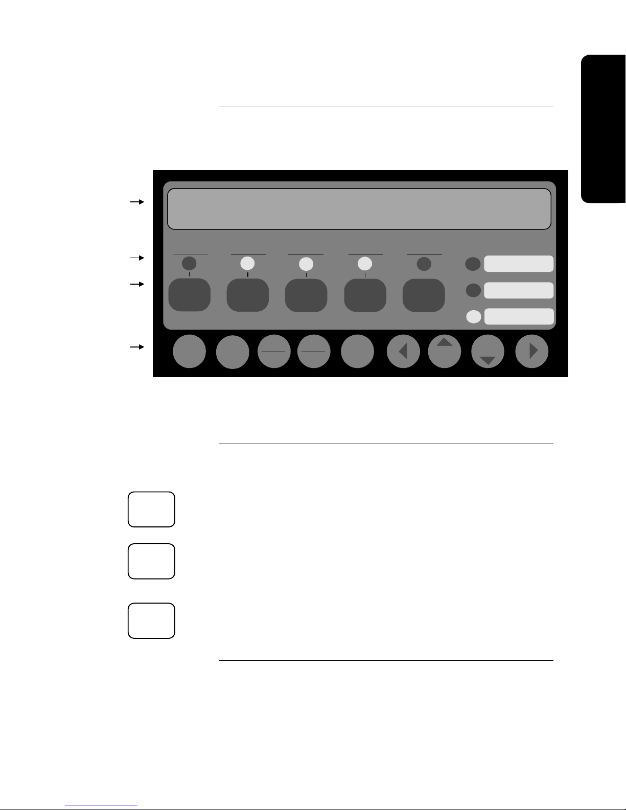
The user interface of the 4010 system consists of control keys, LEDs, a 2-line by
40-character backlit LCD, and a tone-alert mounted in the control panel. The
purposes of the Operator and Menu keys are listed below.
SYSTEM IS NORMAL
**SYSTEM IS NORMAL**
12:02:15pm Thur 04-Jul-96
FIRE
ALARM
ALARM
ACK
Menu
SUPERVISORY
Function
10:09:33am Wed 27-Aug-97
SYSTEM
SUPV
ACK
Disable
Enable
SYSTEM
TROUBLE
TROUBLE
ACK
Exit
Clear
ALARM
SILENCED
ALARM
SILENCE
Enter Previous Next
POWER
SYSTEM
AC
RESET
Figure 1-2. 4010 Operator Interface, Showing High-Level Status
Screen
User Programmed
User Programmed
User Programmed
Operator Key Definitions
ALARM
ACK
SUPV
ACK
TROUBLE
ACK
The following information defines the operator (rectangular) keys on the 4010
panel.
Alarm Acknowledge <ALARM ACK>
The <ALARM ACK> key is used to acknowledge any unacknowledged fire
alarms in the system and to scro l l through the alarms in the active Alarm List.
Supervisory Acknowledge <SUPV ACK>
The <SUPV ACK> key is used to acknowledge any unacknowled ged
supervisories in the system and to scroll thr ough the supervisory conditions in
the active Supervisory List.
Trouble Acknowledge <TROUBLE ACK>
The <TROUBLE ACK> key is used to acknowledge any unacknowledged
troubles in the system and to scroll through the troubles in the active Trouble
List.
Continued on next page
Technical Manuals Online! - http://www.tech-man.com
1-9
Page 24

User Interface, Continued
Operator Key Definitions
(continued)
ALARM
SILENCE
SYSTEM
RESET
Menu Navigation Key
Definitions
Menu
Function
Disable
Enable
Exit
Clear
Alarm Silence <ALARM SILENCE>
The <ALARM SILENCE> key is used to silence any silenceable output types
(generally all non-visible notification appliances).
System Reset <SYSTEM RESET>
The <SYSTEM RESET> key allows you to reset all alarm notification
appliances and controls, remove alarms from the Alarm List, silence all
silenceable outputs, reset detectors, and return the system to a normal state
(provided that no alarms are present). The display will indicate that a reset is in
progress and whether or not a reset completes successfully.
The following information defines the menu navigation (round) keys on the 4010
panel. These keys perform access level dependent functions defined in the
“Passcodes, Access Levels, and Logging In and Out” section of this chapter.
Menu <Menu>
The <Menu> key always brings you to the top of the main menu structure unless
you are in Programming or Quick-CFIG menus (see the Menu Structure at the
back of this chapter).
Function <Function>
The Function Menu is displayed when the <Function> key is pressed at the
High-Level Status screen. Use the < Previous> and <ó Next> keys to scroll
through the functions list. The function key provides access to commonly used
control and display “functions,” and is also used for list editing.
Disable/Enable <Disable/Enable>
The <Disable/Enable> key allows the operator to quickly disable or enable any
point that is currently displayed (passcode protected). A confirmation screen is
displayed requesting <Enter> be pressed before performing the actual enable or
disable.
Exit/Clear <Exit/Clear>
The <Exit/Clear> key is used to back out of menus or displays to get to the toplevel menu structure (refer to the “Menu Structure” at the end of this chapter).
Where possible, the <Exit/Clear> key will back out one level at a time. There
are cases, however, that the <Exit/Clear> key will return the operator directly to
the top level.
Continued on next page
Technical Manuals Online! - http://www.tech-man.com
1-10
Page 25

User Interface, Continued
Overview
Menu Navigation Key
Definitions (continued)
Enter
u t
~
Previous
Next
þ
Enter <Enter>
The <Enter> key is used to confirm selections. When pressed, this key provides
additional information about the point shown on the display. In a programming
screen, pressing <Enter> indicates that the information on the display is correct
and can be entered. The <Enter> key is used in various other places within the
menu structure, always for this same type of operation.
Right <u> and Left Arrow <t>
The <u> and <t> arrows are used in screens with multiple choices. The keys
advance the focus (square brackets [ ] ) from field-to-field.
Previous < Previous> and Next <ó Next>
The < Previous> and <ó Next> keys allow you to move from screen-to-
screen within any displayable object having multiple screens. This would
include scroll ing through an historical log, the point database, a lis t of points, or
other similar activities. The <ó Next> key selects the next display screen in
sequence, and the < Previous> key selects the previous screen. These keys
are also used to view additional information about abnormal points or in viewing
Historical Logs.
Technical Manuals Online! - http://www.tech-man.com
1-11
Page 26

Passcodes, Access Levels, and Logging In and Out
Overview
Passcodes and Access Levels
Certain operator functions of the 4010 are passcode protected at different levels.
This section describes logging in and out at specific access levels.
All operations in the 4010 are protected at a preset level with designated
passcodes to access these operations. The table below shows the basic
operations and menu choices for specific access levels. The default passcodes
are listed for Levels 2 through 4. Refer to the Menu Structure la ter in this
chapter for a complete quick-reference of the main 4010 FACP menus.
Table 1-2. Access Levels and Operations
ACCESS LEVEL OPERATIONS
1
2
Passcode = 2000
3
Passcode = 3000
Ack
Silence
System Reset
All Level 1 Operations, plus:
Set Time/Date
Point Control
Enable/Disable Points
All Level 1 & 2 Operations,
plus:
Clear Logs
Clear Verification Tallies
Programming
- Edit/Clear Point Label
- Restore/Save CFIG
TrueTest
Walk Test
Reports
4
Passcode = 4000
All Level 1,2, & 3 Operations,
plus:
Quick CFIG
Run Diagnostics
Upload/Download
Programming
• Edit Cards
• Edit SMPL Program
• System Options
Restart Panel
• Warm Start
• Cold Start
Continued on next page
Technical Manuals Online! - http://www.tech-man.com
1-12
Page 27

Passcodes, Access Levels, and Logging In and Out, Continued
Overview
Logging In and Out
To execute any of the functions protected at Level 2 or above, you must Login to
the 4010 FACP using a passcode. After completing a task at a certain access
level you should then Logout to return the access level to Level 1. When logged
in at Level 2 or above and you do not press any front panel keys for more than
ten minutes, the 4010 defaults to access level 1.
All passcodes consist of a four-digit number. Logging in at a Level 4 causes a
Service Mode trouble. Note that this trouble can only be cleared by restarting
the panel.
To Login, p erform Steps 1 thro ugh 7 on a 4010 that is at the High-Level Status
screen (refer to Figure 1-2 for an example of this screen). When moving from
one digit to the next, an asterisk (∗) appears in the place of an entered number
for security purposes. See Table 1-2 in the previous section for the default
passcodes.
1. Obtain the appropriate passcode information for the appropriate level.
2. Press <MENU>.
3. Press and hold <óNEXT> until [Login/Logout] is displayed, and then press
<ENTER>.
4. Press and hold <óNEXT> until [Login] is displayed, and then press
<ENTER>.
5. Press <óNEXT> to scroll through the numbers on the display until the
appropriate number is displayed.
6. Press the right arrow <ö> to move the focus brackets [ ] to the next digit
in the passcode.
Repeat Steps 5 & 6 until all numbers are entered.
7. When the passcode is correct, press <ENTER> to Lo gin.
A **Login Accepted** screen indicating your current access level is displayed
briefly upon a successful Login attempt. If you did not enter the appropriate
Login passcode, a **Login is Invalid** screen appears.
To Logout, perform Steps 1 thr ough 4 above exce pt for Step 4 where you ne ed
to wait until [Logout] is displayed.
Technical Manuals Online! - http://www.tech-man.com
1-13
Page 28

1-14
Menu Structure
Technical Manuals Online! - http://www.tech-man.com
Page 29

Chapter 2
Back Box Installation
Overview
In this Chapter
This chapter contains instructions and guidelines for installing the 4010 FACP
backbox.
This chapter discusses the following topics:
Topic See Page #
Before You Begin 2-2
Remove Chassis and Cut Conduit Openings 2-3
Mount the Backbox 2-4
Re-install the Chassis 2-5
Back Box Installation
Technical Manuals Online! - http://www.tech-man.com
2-1
Page 30

Before You Begin
Unpacking the System
Installation Guidelines
Unpack the 4010 using the following information:
• Carefully unpack the system and inspect for shipping damage.
• Select a location for the control panel in a clean, dry, vibration-free area
with moderate temperature (see the “Environmental Specifications” section
in Chapter 1).
Before installing the 4010, read the following guidelines:
• Install the FACP in a readily accessible area with sufficient room to easily
install and maintain the control panel.
• Locate the top of the cabinet approximately five feet above the floor with
the door hinge on the left-hand side.
• Count the number of conductors needed for all devices and cut the
appropriate knockouts. Pay careful attention to the routing for Power-
Limited and Non-Power Limited wiring. You must maintain a 1/4-inch
separation between these two types of wiring. All terminal connections
are Power-Limited except those to the AC power, Battery, and City
Circuit, and contacts when switching Non-Power Limited sources.
• Review the precautions and warnings at the front of this publication.
• All wiring must comply with the National and/or Local codes for fire alarm
systems. All wiring must test free of grounds.
• Leave sufficient room for batteries in the bottom of the back box (see the
label inside the 4010 back box for more information).
• Enclosure must be level and plumb when installed.
Standards and Codes
When installing the 4010, you should be familiar with the following standards:
• NEC Article 300 Wiring Methods
• NEC Article 760 Fire Protective Signaling Systems
• Applicable Local and State Building Codes
• Requirements of the Local Authority Having Jurisdiction (AHJ)
2-2
Technical Manuals Online! - http://www.tech-man.com
Page 31

Remove Chassis and Cut Conduit Openings
Overview
Step 1. Remove the Chassis
The 4010 ships from the factory completely assembled in the back box, or as a
single piece electronics assembly that is shipped separately from the back box,
retainer, and door. The system electronics (SFI/O and power supply) are
mounted to a steel chassis. Refer to the 526-407 label inside the back box for
additional information.
Prior to installation you must remove the chassis containing the 4010 SFI/O and
power supply from the back box. Use the following steps to remove the chassis.
1. Remove the door grounding wire from the back box. Remove the door from
the hinges and set it aside.
2. Remove the metal retainer by gently lifting and pulling the bottom of the
retainer out from the back box. Then, being careful not to drop the retainer,
slide the top of the retainer out from under the lip of the top of the back box.
3. Remove the AC wiring Quick-Disconnect connector from the chassis by
firmly squeezing the release tabs and pulling it free. The Quick-Disconnect
connector is located directly below the chassis. Dress the wires so that they
do not interfere with back box installation.
4. Loosen or remove the four mounting screws holdi ng the chassis to the back
box.
5. Lift the chassis out of the back box and store in a clean, dry, safe area for reinstallation later.
Back Box Installation
Step 2. Cut Conduit
Entrances
Determine the amount and proper location of conduit/service entrances. Make
all appropriate entrances into back box (see Figure 2-1).
Caution: Power-Limited and Non-Power-Limited wiring must enter
through separate conduit/service entrances. AC power
entrance into back box is recommended at the bottom right
side of the back box.
If a Bus Bar is required to terminate wire shields, see Figure 2-1 for proper
mounting location. Entrances for shielded wire must be located within two
inches of the bus bar. Maximum intrusion into box for conduit is 1/2-inch.
TYPICAL
CONDUIT
LOCATION
BUS BAR MOUNTING STUDS
2" MAX IF
USING BUS BAR
TOP VIEW
Figure 2-1. Conduit and Bus Bar Mounting Locations.
Technical Manuals Online! - http://www.tech-man.com
2-3
Page 32

Mount the Backbox
Surface Mounting the Back
Box
Semi-Flush Mounting the
Back Box
1. Using the pre-cut holes in the back of the box as a guide, mark off where
you want to mount the back box (see the “Before You Begin” section of this
chapter).
2. Using mounting hardware capable of supporting a fully loaded 4010
(approximately 50 lbs.), screw two screws into the wall where the top two
teardrop holes of the back box are to be located. Tighten the screws leaving
about a 1/8-inch gap from the seated position.
3. Carefully lift the back box and place the two teardrop holes over the
mounting screws.
4. Screw two mounting screws into the two bottom back box holes and tighten
all screws.
1. Remove the mounting knockouts from both sides of the back box. See
Figure 2-2 for their location.
2. Make the appropriate opening in the wall or wall board to accommodate the
back box. Dimensions of the backbox are 22” (55.8 cm) W x 18 (45.7 cm)
H x 6 ¼ (15.8 cm) D.
3. Frame the opening to accommodate the back box. Fit the back box into the
opening. Use wall stud guides to ensure free movement of the door.
4. Using mounting hardware capable of supporting a fully loaded 4010, screw
or nail back box to the studs.
DOOR
6 1/4"
5 3/8"
FRONT OF STUD FOR
1/2" WALLBOARD
FRONT OF STUD FOR
5/8" WALLBOARD
WALL STUD GUIDES
(1/2" WALL BD)
WALL STUD GUIDES
(5/8" WALL BD)
KNOCKOUT
SCREW/NAIL HOLES
(FOR SEMI
FLUSH MOUNT.)
SIDE VIEW
Figure 2-2. Wall Stud Guides
Technical Manuals Online! - http://www.tech-man.com
Continued on next page
2-4
Page 33

Re-install the Chassis
Procedure
Use the following steps to re-install the 4010 chassis containing the SFI/O and
power supply into the back box.
1. Insert two mounting screws into the top two mounting holes for the chassis.
Tighten the screws leaving a 1/8-inch gap from the seated position.
Caution: When mounting the chassis, pay careful attention to any
2. Carefully hang the chassis on the two top mounting screws using the top
teardrop holes on the chassis.
3. Insert two mounting screws into the bottom two teardrop chassis mounting
holes and tighten all screws.
4. Re-hang the door on the back box hinges and re-attach the door grounding
wire to the back box.
5. You can re-install the retainer now before wiring or later after wiring is
complete. Re-install the retainer by guiding the top lip of the retainer under
the top lip of the back box and carefully sliding the bottom of the retainer
into place.
WARNING: DO NOT APPLY POWER TO THE 4010 AT THIS TIME!
wiring inside the back box. Do not crimp any wiring behind
the chassis when mounting.
Back Box Installation
DO NOT connect the quick-disconnect AC connector to
the chassis. Refer to the “Power-Up and Checkout”
section of this publication for more information.
Technical Manuals Online! - http://www.tech-man.com
2-5
Page 34

This is blank
Technical Manuals Online! - http://www.tech-man.com
Page 35

Chapter 3
g
Wiring
Overview
In this Chapter
This chapter contains instructions and guidelines for wiring the 4010 FACP.
This chapter describes how to wire the base 4010 FACP. Use the information in
this chapter, the 526-407 and 526-408 labels located on the inside door of the
FACP, and the 842-058 Field Wiring Diagram to wire the base panel.
Refer to the publications listed in Chapter 1 to wire all optional modules.
This chapter discusses the following topics:
Topic See Page #
Overview 3-2
NAC Wiring 3-4
IDNet Wiring 3-5
AC Power and Battery Wiring 3-6
Auxiliary Relays 3-9
System Power Up and Checkout 3-10
Periodic Testing and Maintenance 3-13
Wirin
Technical Manuals Online! - http://www.tech-man.com
3-1
Page 36

Overview
Power Limited Versus NonPower Limited Systems
The 4010 system can be wired as either a Power Limited or Non-Power Limited
system. Adhere to the following guidelines and consult the NEC for specifics.
• When installing the 4010 as a Power Limited system, you must observe the
following guidelines:
- Maintain ¼ inch of space between Power Limited wiring and AC Power
or Battery wiring.
- Run AC Power wiring in a separate conduit that enters the back box in
the upper or lower right corner.
- Route AC Power, battery wiring, city circuit connections, and non-
Power Limited Rela y wiring o nl y thr ough the shaded ar eas shown in
Figure 3-1. Do not route Power Limited wiring through the shaded
areas shown in the figure.
• The 4010 FACP can be reclassified as a non-Power Limited system when
installed in accordance with the latest version of NEC 760. In this case, all
references to Power Limited must be removed from the panel’s labels.
8 1/2"
22"
DISCARD
AFTER
SHIPPING
18"
14.5"
BATTERY AREA
NO CONDUIT ENTRY OR
WIRING IN THIS AREA
FRONT VIEW
AC POWER
HARNESS
AC TERMINAL
BLOCK
SHADED AREA
IS FOR NON-POWER
LIMITED WIRING ONLY
Figure 3-1. Location of Non-Power Limited Wiring Area
Technical Manuals Online! - http://www.tech-man.com
3-2
Page 37

Overview, Continued
g
Locations of Terminal
Connections
Figure 3-2 shows the location of all terminal connections for the system
components. Refer to the appropriate section later in this chapter for specific
information on wiring a component.
4010-9806
Class A
Module
(565-789)
Pot for LCD Adjustment
4010-9806
Class A
Module
(565-789)
4010-9809
City Module
Expansion Power
Supply (565-792)
Supression Power
Supply (565-793)
4010-9813
or
4010-9814
Battery Meter
Module
4010-9820
Wirin
WARNING: PTCs MUST NOT TOUCH EACH OTHER OR
ANY OTHER METAL SURFACE!
Figure 3-2. Base Panel Wiring
3-3
Technical Manuals Online! - http://www.tech-man.com
Page 38

NAC Wiring
Overview
Terminal Connections
The 4010 provides four NACs for notification appliances such as horns and
strobes. These NACs are standard Class B (Style Y). Optional Class A (Style
Z) operation can be achieved using an adapter. Refer to the 4010-9806 Class A
Module - Installation Instructions, Part No. 574-055 for information on the Class
A NAC adapter.
The NACs supervise for short or open circuit troubles. In the event of a short,
the NAC does not energize. Each NAC is rated at 2A. Up to 4A of NAC power
is available from the base unit. If more power is needed, NAC 3 and NAC 4 can
be connected to an expansion power supply.
An auxiliary (AUX) power connection (rated at 1/2A, 24VDC) is provided at
TB5 located to the left of the auxiliary (AUX) relay terminal blocks at the
bottom center of the SFI/O. Current drawn from TB5 must be deducted from the
4A total NAC power.
Each NAC can be configured as “On until Silence” or “On until Reset” and can
be coded or non-coded (refer to “Chapter 6 - Configuring Poi nts” for more
information). The 4010 can disconnect each NAC individually to aid in locating
earth faults.
The NAC’s wiring connects to TB1 and TB2 as shown in Figure 3-3. These
terminal blocks are barrier strip type that can accommodate 12-18 AWG wires.
TB1 and TB2 are located in the upper left corner of the SFI/O. Refer to the 842058 wiring diagram for Alarm Current, Wiring Distance, and Line Resistance
values.
TB1-1: NAC 1 + Alarm
TB1-2: NAC 1 - Alarm
TB1-3: NAC 2 + Alarm
TB1-4: NAC 2 - Alarm
TB2-1: NAC 3 + Alarm
TB2-2: NAC 3 - Alarm
TB2-3: NAC 4 + Alarm
TB2-4: NAC 4 - Alarm
NAC 1 NAC 2 NAC 3 NAC 4
TB1 TB2
Technical Manuals Online! - http://www.tech-man.com
Alm+ Alm- Alm+ Alm-
1 2 3 4
Figure 3-3. NAC Wiring
3-4
Alm+ Alm- Alm+ Alm-
1 2 3 4
Page 39

IDNet Wiring
g
Overview
Terminal Connections
The 4010 uses addressable IDNet devices (smoke and heat detectors/sensors and
pull stations, 4009 IDNet NAC Extender, etc.). The 4010 supports 250 devices
on a single pair of wires on a single channel.
The IDNet channel supports Style 4 and 6 as part of the base system. Refer to
the 4010 Field Wiring Diagram (842-058) for all wiring information.
IDNet communication also supports the detection of duplicate devices. IDNet
detects if two devices are set to the same address. This function is activated
from the front panel (see IDNet Diagnostics in the Diagnostic/Troubleshooting
section of this publication).
Use the information below to wire the IDNet communication lines (14-18 AWG)
to TB4 located in the upper right corner of the SFI/O.
• To connect Class A wiring, wire the “B” terminals (TB4-1 and -2) to each
device in succession without T-taps (observe polarity). At the last device in
the loop, return the B+ wire to the A+ terminal (TB4-4) and the B- wire to
the A- terminal (TB4-5).
• To connect Class B wiring, jumper B+ to A+ and B- to A- using 14-18
AWG insulated wire (T-taps are allowed). Connect B+ to all devices
(positive connection) and connect B- to all devices (negative connection).
IDNet Comms
Wirin
A- A+ SHLD B- B+
TB4
6 5 4 3 2 1
Figure 3-4. IDNet Connections
Technical Manuals Online! - http://www.tech-man.com
3-5
Page 40

AC Power and Battery Wiring
AC Power
1. Match incoming Neutral and Hot wires
to their corresponding wires leading
from the terminal block located in the
lower right corner of the back box to
the Quick-Disconnect harness and
screw into place.
2. The safety ground wire from the AC
source must be connected to the
ground stud located below the terminal
block. Do the following to connect the
ground wire to the stud:
a) Run the ground wire to the stud
and cut it, leaving a little slack for
adjustment.
b) Crimp a spade terminal (Part No.
474-144 or -015) onto the ground
wire.
c) Place a lock washer on the stud,
followed by the terminal and then
another lock washer.
d) Securely fashion a nut (Part No.
322-128) onto the stud.
When the 4010 FACP is installed as a Power-Limited system, AC power lines
must be run in a separate conduit, and should enter the back box in the lower
right corner. Use the shaded area of Figure 3-5 only for routing of AC power
wiring. All wiring must be neatly dressed within the back box. Use the wiring
guides inside the back box when possible.
• The FACP requires connection to a separate dedicated AC fire alarm circuit,
which must be labeled “Fire Alarm.”
• The AC power circuit must connect to the line side of the main power feed
of the protected premises.
• No other equipment can be powered from the fire alarm circuit.
• The AC power circuit wiring must run continuously, without any disconnect
devices, from the power source to the FACP.
• Over-current protection for this circuit must comply with Article 760 of the
National Electric Code as well as local codes.
• Use 12AWG wire with 600-volt insulation for this circuit.
WIRE
GUIDES
AC POWER
HARNESS
14.5"
BATTERY AREA
NO CONDUIT ENTRY OR
WIRING IN THIS AREA
AC TERMINAL
BLOCK
SHADED AREA
IS FOR NON-POWER
LIMITED WIRING ONLY
Technical Manuals Online! - http://www.tech-man.com
Figure 3-5. AC Power Wiring
Continued on next page
3-6
Page 41

AC Power and Battery Wiring, Continued
g
Installing and Connecting
Batteries
The base 4010 FACP accommodates (and charges) up to 25 Ah capacity
batteries. The following is a list of compatible batteries.
• 2081-9272, 6.2 Ah
• 2081-9274, 10 Ah
• 2081-9275, 18 Ah
• 2081-9288, 12.7 Ah
• 2081-9287, 25 Ah
Install the batteries in the area shown on the label located in the bottom of the
back box. Use the following steps, Part No. 733-945 battery harness (733-903
for Canadian systems), and Figure 3-6 to connect the batteries to TB8 located in
the lower left corner of the SFI/O.
Domestic systems should use the following procedure.
1. Using the short white wire crimped at both ends, jumper one positive (+)
terminal of one battery to the negative (-) terminal of the other battery.
2. Take the non-crimped end of the red wire from the harness and connect this
to the + side of TB8. Connect the Fast-on connector on the other end of the
Red wire to the Positive terminal of one of the batteries.
3. Take the non-crimped end of the black wire from the harness and connect
this to the - side of TB8. Connect the Fast-on connector on the other end of
the Black wire to the Negative terminal of one of the batteries.
TB8
Wirin
Figure 3-6. Battery Connections – Domestic System
Canadian systems should use Figure 3-7 as an installation guide.
WARNING: DO NOT APPLY BATTERY POWER TO THE 4010 AT
Technical Manuals Online! - http://www.tech-man.com
− BATTERY +
THIS TIME! DO NOT connect crimped ends of the red
and black wires to the battery. Refer to the “Power-Up
and Checkout” section of this publication for more
information.
Continued on next page
3-7
Page 42

AC Power and Battery Wiring, Continued
Installing and Connecting
Batteries (continued)
CANADIAN LOW BATTERY MODULE
P4
SF I/O BD
TB8
565-738
BTRY
BATTERY HARNESS
733-903
RED
BLK
RELAY
RED
5
3
1
RED
6
4
2
BATTERY BATTERY
Figure 3-7. Canadian Battery Wiring
WARNING: DO NOT APPLY BATTERY POWER TO THE 4010 AT
THIS TIME! DO NOT connect crimped ends of the red
and black wires to the battery. Refer to the “Power-Up
and Checkout” section of this publication for more
information.
Technical Manuals Online! - http://www.tech-man.com
3-8
Page 43

Auxiliary Relays
g
Auxiliary Relays
The 4010 provides two auxiliary (AUX) relay circuit connections; one at TB6
and the other at TB7. Each circuit provides one form “C” contact (normally
open or normally closed) rated at 2A (24VDC), or 0.5A (120 VAC) with
optional 120 Volt auxiliary relay kit.
The default operation for AUX1 is an Alarm Relay and AUX2 is a Trouble
Relay. The AUX relay circuits can also be programmed for other desired
operations using the front panel (see “Chapter 6 - Configuring Points”).
Use Figure 3-8 to wire the AUX relay circuits. TB6 and TB7 are located at the
bottom of the SFI/O near the center.
When power for the AUX relay contacts is from TB5 (AUX Power), 4010-9813,
or 4010-9814 expansion power supplies, the circuit is power-limited. When
power for the AUX relay contacts IS NOT from the sources listed above, use an
in-line fuse (Part No. 208-165). If power source is non-power-limited, wiring
must be routed through the non-power-limited spaces shown in Figure 3-1 and
“power-limited” markings must be obliterated.
TB6 TB7
NO C NC
NC C NO
Wirin
Bottom of the SFI/O
AUX1 AUX2
Figure 3-8. AUX Relay Connections
Technical Manuals Online! - http://www.tech-man.com
3-9
Page 44

System Power-Up and Checkout
Connect AC & Battery Power
Power-Up and Checkout
Use the following steps to apply AC and battery power to the 4010 FACP.
1. Re-connect the AC power harness removed in previous steps
2. Connect the crimped ends of the 733-945 battery harness (733-903 for
Canadian systems) to the batteries. Observe polarity (red to +, black to -)
when connecting batteries.
WARNING: Battery contains sulfuric acid which can cause severe
burns to the skin and eyes, and can destroy fabrics.
Replace any leaking or damaged battery. If contact is
made with sulfuric acid, immediately flush skin or eyes
with water for 15 minutes and seek immediate medical
attention.
Caution: Notify fire, central station, and/or building personnel before
testing the system.
Power-Up
After applying power to the system, use the following list to check the 4010 for
proper operation.
• Check that the green AC Power LED is ON.
• Check that all yellow and red LEDs are OFF.
• Use the Lamp Test procedure in “Chapter 11 - Operation” of this
publication to verify that all 4010 LEDs and LCD segments work properly.
On power-up, the 4010 performs the following:
• Displays revision of boot-loader software
• Self Test - CPU Hardware Checkout
• Linkscan - Checking for a Programmer Unit Connection
• Memory Scan - Checking for Incorrect Application
• Start up - 4010 FACP Startup
Start up
Technical Manuals Online! - http://www.tech-man.com
Figure 3-9. 4010 Start Up Screen
Continued on next page
3-10
Page 45

System Power-Up and Checkout, Continued
g
Power-Up and Checkout
(continued)
Custom Label
Point Type
If the 4010 passes its start up self-test, the FACP starts and the system is normal,
the High-Level Status screen shown in Figure 3-10 displays. If troubles exist in
the system, Figure 3-11 displays after pressing <ACK>.
Note: The High-Level Status screen is the first screen shown on a 4010
whether in a normal or a trouble/supervisory/fire alarm state
before any keys are pressed.
SYSTEM IS NORMAL
10:09:33am Wed 27-Aug-97
Figure 3-10. System Normal (High Level Status) Screen
FIRE=0 SUPERVISORY=0 TROUBLE=3
[TrueAlarm] Add 1/130
FIRST FLOOR EAST WING ROOM 12
Smoke Detector Trouble 1/3
Device Condition
Figure 3-11. System Trouble Screen
Note: If the self-test fails, the 4010 displays the error code and waits 45
seconds before attempting a restart. Refer to Chapter 10 for a
list of error codes.
Checkout
Caution: Before proceeding with the acceptance test procedures, do
the following:
• Notify the fire department and the central alarm receiving station if
transmitting alarm conditions.
• Notify building personnel of the test so that alarm sounding devices are
disregarded during the test session.
• When necessary, disable activation of alarm notification appliances and
speakers to prevent their sounding.
Continued on next page
First of
Three
Troubles
Wirin
Technical Manuals Online! - http://www.tech-man.com
3-11
Page 46

System Power-Up and Checkout, Continued
Acceptance Test
When finished with the original installation and all modifications, conduct a
complete operational test on the entire installation to verify compliance with
applicable NFPA standards. Testing should be conducted by a Simplex-trained
technical representative in the presence of a representative of the Authority
Having Jurisdiction, and the customer’s representative. Follow the procedures
outlined in Chapter 7 “Inspection, Testing, and Maintenance” of NFPA Standard
72-1996 and the following steps.
1. Activate an initiating device (smoke, pull, etc.) and check that all active
notification appliances (strobes, horns, etc.) function. Reset the alarm
initiating device, the FACP, and any other associated equipment. Repeat
this step for each initiating device.
2. Remove AC power, activate an initiating device, and check that active
notification appliances sound, and alarm indicators illuminate. Measure the
battery voltage with notification appliances active. Replace any battery with
a voltage of less than 24VDC and reapply AC power.
Note: Step 2 requires fully charged batteries. If batteries are new or
discharged due to a recent power outage, allow the batteries to charge
for 48 hour s before testing. Refer to “Periodic Testing and
Maintenance” section for more information on testing batteries.
3. Reapply AC power and check that all yellow and red LEDs are OFF and the
green AC Power LED is ON.
Caution: Notify fire, central station, and/or building personnel when
you finish testing the system.
Technical Manuals Online! - http://www.tech-man.com
3-12
Page 47

Periodic Testing and Maintenance
g
Overview
Battery Testing Information
Periodic testing and maintenance of the FACP, all initiating and notification
devices, and any other associated equipment is essential to ensure proper and
reliable operation. Test and maintain the FACP according to the schedules and
procedures outlined in the following publications:
• NFPA Standard 72-1996, Chapter 7, “Inspection, Testing, and
Maintenance.”
• Installation Instructions for the peripheral devices installed in your system.
Correct any trouble condition or malfunction immediately.
Periodic testing and maintenance of the system batteries must be done to ensure
proper and reliable back-up operation. Test and maintain the system batteries
using the following information.
All sealed lead -acid batteri es in fire alarm service should be tested annually.
Replace all sealed lead-acid batteries that have been in service for four or more
years.
It is recommended that a battery tester made specifically for checking sealed
lead-acid batteries be used. Such a tester is available under Service Part No.
553-602.
If a battery tester is unavailable, the “voltage response test” described in the
following information can be used to detect batteries with very low capacity or
shorted cells.
Caution: A defective battery charger circuit can cause battery failure.
Check the condition of the battery charger when either a
battery tester or a voltage response test reveals weakened
batteries.
Voltage Response Test
1. Disconnect battery from system.
2. Connect a digital voltmeter across the battery.
3. Connect the appropriate sized resistor(s) (see Table 3-1) across the battery’s
terminals for the listed test time.
Caution: Resistors will get hot during test! Use 12AWG wire for
battery-to-resistor hookup.
4. Record the end voltage reading.
5. Treat the battery as described in Table 3-2.
Continued on next page
Wirin
Technical Manuals Online! - http://www.tech-man.com
3-13
Page 48

Periodic Testing and Maintenance, Continued
Battery Testing Information
(continued)
Voltage Amp Hr Resistor
12 6.2 6.0 50 380-031 2 Seconds
12 8 4.5 50 380-031 (adj to 4.5 Ohm) 2 Seconds
12 10 4.0 50 380-031 (adj to 4 Ohm) 2 Seconds
12 18 2.0 100 380-031 (3 in parallel) 2 Seconds
12 25 1.5 100 382-090 (2 in parallel) 2 Seconds
12 33 1.0 150 382-090 (3 in parallel) 2 Seconds
6* 50 1.0 150 382-090 (3 in parallel) 4 Seconds
12 110 1.0 150 382-090 (3 in parallel) 4 Seconds
*Test 2 batteries in series for 12V
Table 3-1. Battery Testing
Watts Part No. and Description Test Time
(Ohms)
Table 3-2. Battery Readings and Instructions
If end voltage reading of battery is: Instructions
11.8V or more Put in Service
11.7V to 11.0V Charge Battery*
10.9V or less Discard Battery
*Retest battery after charging
Discard battery after four or more years of service. Dispose of according to
manufacturer’s guideli nes.
Technical Manuals Online! - http://www.tech-man.com
3-14
Page 49

Chapter 4
g
g
Quick CFIG
Overview
Cautions and Warnings
The Quick CFIG option provides you with the ability to quickly and
automatically program the components and features of the 4010. Quick CFIG is
especially useful for programming basic system components following a new
installation, and for adding components to an existing installation.
Quick CFIG functions include the following:
• Reconfigure All Hardware
• Autodetect all new hardware added since CFIG was last saved
• Restore the Factory CFIG
• Accept default settings for system options
• Edit settings of system options
Be alert to the following when using Quick CFIG:
• WARNING: The 4010 System will NOT continue to operate as a Fire
Alarm System during the programming of Quick CFIG operations.
• Quick CFIG performs an IDNet duplicate address search, and terminates if
duplicate addresses are found.
• Using the Quick CFIG options changes the 4010 configuration. When
changing the configur ation, information could be lo st.
• Quick CFIG is not allowed if a DACT or Network card is installed. Use
Quick CFIG first, and then program the DACT or network card.
• Class A Adapters are not automatically detected by Quick CFIG. Refer to
Chapter 6 for information on programming a Class A NAC.
• TrueAlert Non-Addressable functions are not accessible through Quick
CFIG. You must manually program the appropriate NACs with the
TrueAlert point type to enable TrueAlert operation. Refer to Chapter 6 for
information on manually programming a NAC’s point type.
• Quick CFIG automatically configures the hardware device type for a 4009
(4009A, R4009A, 4009A8, R4009A8). All 4009 NACs are set for Class B
operation and assigned a point type of SSIGNAL.
Pro
rammin
In this Chapter
This chapter discusses the following topics:
Reconfigure All Hardware 4-2
Auto Detect New Hardware 4-3
Restore Factory CFIG 4-4
Accept Default Settings for System Options 4-5
Edit Settings for System Options 4-6
Technical Manuals Online! - http://www.tech-man.com
Topic See Page #
4-1
Page 50

Reconfigure ALL Hardware
Overview
Procedure
This option starts the 4010 with a new configuration. If a configuration already
exists and this option is selected, it clears the current configuration and adds all
currently connected devices to the CFIG.
1. Press <MENU>.
2. Press <NEXT> or <PREVIOUS> until [Quick CFIG] is displayed and
then press <ENTER>. A warning appears, indicating that the 4010 is no
longer in the Fire Alarm Operation mode.
3. Press <ENTER> to continue with the Quick-CFIG option.
4. Press <NEXT> or <PREVIOUS> until <RECONFIGURE ALL
5. Press <ENTER> to c ontinue. Another warning appears, indicating that you
A message appears indicating that Quick CFIG is reconfiguring the hardware.
This message is followed by another, which indicates that Quick CFIG is
scanning for IDNET device s . The Reconfigure ALL Hardware function is
complete when a message similar to the following appears.
Refer to “Save CFIG Option” at the end of this chapter for information on saving
the CFIG once you have reconfigured the hardware.
Please Wait . . .
Fire Alarm Operation Suspended
HARDWARE> is displayed and then press <ENTER>. A warning
appears, indicating that this will delete the current configuration.
WARNING <Enter> to Continue WARNING
This will DELETE current configuration
need to press <ENTER> to confirm the deletion.
WARNING <Enter> to Continue WARNING
Press <Enter> to confirm deletion
** Automatic Hardware Detection Completed **
Total IDNet Devices Added: 128
Technical Manuals Online! - http://www.tech-man.com
4-2
Page 51

Auto Detect NEW Hardware
g
g
Overview
Procedure
This option adds new hardware that is not currently in the CFIG. All existing
hardware and programming remains the same.
1. Press <MENU>.
2. Press <NEXT> or <PREVIOUS> until [Quick CFIG] is displayed and
then press <ENTER>. A warning appears, indicating that the 4010 is no
longer in the Fire Alarm Operation mode.
3. Press <ENTER> to continue with the Quick-CFIG option.
4. Press <NEXT> or <PREVIOUS> until <AUTO DETECT NEW
5. Press <ENTER> to c ontinue. Another warning appears, indicating that you
A message appears indicating that Quick CFIG is reconfiguring the hardware.
This message is followed by another, which indicates that Quick CFIG is
scanning for IDN ET devices. The Auto Dete ct NEW Hard war e function is
complete when a message similar to the following appears.
Refer to “Save CFIG Option” at the end of this chapter for information on saving
the CFIG once you have reconfigured the hardware.
Please Wait . . .
Fire Alarm Operation Suspended
HARDWARE> is displayed and then press <ENTER>. A warning
appears, indicating that this will change the current configuration.
WARNING <Enter> to Continue WARNING
This will CHANGE current configuration
need to press <ENTER> to confirm the hardware detection operation.
WARNING <Enter> to Continue WARNING
Press <Enter> to confirm Detect NEW
** Automatic Hardware Detection Completed **
Total IDNet Devices Added: 128
Pro
rammin
Technical Manuals Online! - http://www.tech-man.com
4-3
Page 52

Restore Factory CFIG
Overview
Procedure
This option restores the 4010 to its original (factory default) CFIG. All pseudo
points (Analog and Digital) are cleared, Custom Control is erased, etc.
1. Press <MENU>.
2. Press <NEXT> or <PREVIOUS> until [Quick CFIG] is displayed and
then press <ENTER>. A warning appears, indicating that the 4010 is no
longer in the Fire Alarm Operation mode.
3. Press <ENTER> to continue with the Quick-CFIG option.
4. Press <NEXT> or <PREVIOUS> until <RESTORE FACTORY
5. Press <ENTER> to c ontinue. The fol l owing message appears, indicating
This message is followed by a series of internal test messages. The High-Level
Status screen appears when the operation is complete.
Please Wait . . .
Fire Alarm Operation Suspended
CONFIG.> is displayed and then press <ENTER>. A warning appears,
indicating that this will delete the current configuration.
WARNING <Enter> to Continue WARNING
This will DELETE current configuration
that the system is restoring the factory default configuration.
** Restoring Factory Default Panel **
Technical Manuals Online! - http://www.tech-man.com
4-4
Page 53

Accept Default Settings for System Options
g
g
Procedure
1. Press <MENU>.
2. Press <NEXT> or <PREVIOUS> until [Quick CFIG] is displayed and
then press <ENTER>. A warning appears, indicating that the that the 4010
is no longer in the Fire Alarm Operation mode.
3. Press <ENTER> to continue with the Quick-CFIG option.
4. Press <NEXT> or <PREVIOUS> until <ACCEPT DEFAULT
5. Press <ENTER> to c ontinue. The fol l owing message appears, indicating
Please Wait . . .
Fire Alarm Operation Suspended
OPTIONS> is displayed and then press <ENTER>. A warning appears,
indicating that this operation may change current settings.
WARNING <Enter> to Continue WARNING
This may CHANGE current setting
that the system is restoring the default settings for system options.
** Default Settings Restored **
Technical Manuals Online! - http://www.tech-man.com
Pro
rammin
4-5
Page 54

Edit Settings for System Options
Overview
Procedure
Once this action is selected from the Quick CFIG menu, you can set these
options by scro lling through the choic es shown in Table 4-1 and selecting the
appropriate settings for each. For timer options, selecting “0”initiates the action
immediately.
1. Press <MENU>.
2. Press <NEXT> or <PREVIOUS> until [Quick CFIG] is displayed and
then press <ENTER>. A warning appears, indicating that the 4010 is no
longer in the Fire Alarm Operation mode.
3. Press <ENTER> to continue with the Quick-CFIG option.
4. Press <NEXT> or <PREVIOUS> until <EDIT SYSTEM OPTIONS> is
5. Use the <NEXT> and <PREVIOUS> keys to scroll through the system
Table 4-1. System Options and Available Settings
System Option Settings
Please Wait . . .
Fire Alarm Operation Suspended
displayed and then press <ENTER>.
options. Edit each of the system options as necessary, using the information
in Table 4-1. Refer to Chapter 7 for specific information on system options.
Time/Date Format Choose 12 or 24-Hour Format
Active Status Reminder Choose:
• On/Off; default Off
• Set Reminder Interval (1-12 Hours); default = 8
• Signal Duration (0-60 Secs.) 0=ON til clear
default = 5
Alarm Silence/Reset Inhibit Choose a timer range from 0 - 60 Mins; default = 0
Alarm Cut-out Timer Choose a timer range from 0 - 60 Mins; default = 0
Door Drop on Alarm Choose a timer range from 0 - 60 Secs; default = 0
Door Drop on AC Power Loss Choose a timer range from 0 - 60 Mins; default = 0
Audible NAC Operation Choose:
• Audible NACs: Steady
• Audible NACs: Slow March
• Audible NACs: Fast March
• Audible NACs: Temporal (default)
Continued on next page
Technical Manuals Online! - http://www.tech-man.com
4-6
Page 55

Edit Settings for System Options, Continued
g
g
Procedure (continued)
Visual NAC Operation Choose:
TrueAlert Non-Addressable
NAC Horn Operation
Depleted Battery Cutout Choose ON or OFF; default = OFF. Note: Set Depleted
Stagger Start AHU Choose a timer range from 0 - 60 Secs; default = 30
Enable City Circuit Choose ON or OFF; default = OFF
Expansion Power Choose ON or OFF; default = OFF
Suppression Release
(refer to “Chapter 7 - System
Options” for more information)
Table 4-1. System Options and Available Settings (continued)
System Option Settings
• Visual NACs: Steady
• Visual NACs: Slow March
• Visual NACs: Fast March
• Visual NACs: Temporal
• Visual NACs: Synchronous (default)
Choose:
• Temporal (default)
• Steady
• Slow March
Battery Cutout to ON for suppression release systems.
Choose:
• ON or OFF (default = OFF)
• Dual Detector (default = OFF)
• Detector Delay (default = 60)
• Manual Delay (default = 30)
Edit Passcodes* Change Passcode Designations
Logical Zone Labels* Apply Zone Labels
*Available under Quick-CFIG System Options Menu Only.
4-7
Pro
rammin
Technical Manuals Online! - http://www.tech-man.com
Page 56

Save CFIG Option
Overview
Depending on whether or not you will be doing additional programming (such as
changing hardware and point types, etc.), you may want to save the CFIG
following the Quick CFIG operation.
The Save CFIG option saves all information to the 4010 configuration after or
during programming. Choose this option if you wish to save all of your edits
and modifications you made during your programming session to the 4010
configuration. You can Save CFIG by choosing the menu option or pressing
Exit/Clear to back out of Programming mode and then choosing the Save CFIG
option from the 4010 prompts.
When exiting the programming mode, your 4010 re-boots and becomes
operational as a fire alarm system.
Technical Manuals Online! - http://www.tech-man.com
4-8
Page 57

Chapter 5
g
g
Configuring Cards
Overview
In this Chapter
The 4010 allows you to manually configure each option card in the system. This
chapter describes how to add, delete, or modify optional cards in the 4010
FACP.
Note: The system must be powered down before cards are added to
the system.
This chapter discusses the following topics:
Topic See Page #
Card Addresses 5-2
Adding, Deleting, or Modifying 4010 Cards 5-3
Technical Manuals Online! - http://www.tech-man.com
Pro
rammin
5-1
Page 58

Card Addresses
Card Addresses
All card addresses (whether hardware or logical cards) are shown in Table 5-1.
Table 5-1. 4010 Card Addresses
Card Address Reserved Cards
0 CPU Board
1 NAC/Relay circuits
2 Power Supply
3 IDNet Channel
4 Dual RS232 or Service Modem
5 - 7 Unused
8 4120 Network or DACT cards
9 - 14 N2 Slaves (24-Point I/O or LCD Annunciator)
15 - 16 Unused
17 4009 IDNet NAC Extender
18 System Digital Pseudo Points
19 User Digital Pseudo Points
20 System Analog Pseudo Points
21 User Analog Pseudo Points
22 System List Pseudo Points
23 User List Pseudo Points
Technical Manuals Online! - http://www.tech-man.com
5-2
Page 59

Adding, Deleting, or Modifying 4010 Cards
g
g
Overview
Adding a Card
This section describes how to add, delete, or modify cards in a 4010 FACP. Be
aware of the following configuration rul es when adding, deleting, or modifying
cards.
• Cards 1 through 3 and 17 through 23 cannot be deleted.
• Certain cards are mutually exclusive. For example:
- One 4120 Network Card or One DACT is allowed.
- One Dual RS232 Card or One RS232/Modem is allowed.
• The City Circuit card and Expansion Power Supply are enabled via the
System Options menu. Refer to Chapter 7 for information on doing this.
• The DACT and Network cards are programmed and added to the 4010
FACP via the 4010 PC Programming tool.
Use the following steps to add a card to the 4010 FACP.
1. Press <MENU>.
2. Press <NEXT> or <PREVIOUS> until [PROGRAMMING] is displayed
and then press <ENTER>. A warning appears, indicating that the 4010 is
no longer in the Fire Alarm Operation mode.
3. Press <ENTER> to continue.
4. Press <NEXT> or <PREVIOUS> until <CONFIGURE CARDS> is
5. Press <NEXT> or <PREVIOUS> until <ADD 4010 CARD> is displayed.
6. Press <NEXT> or <PREVIOUS> to sc roll through the cho ices listed
7. Once the desired card is displayed, press Enter. The RS232 and Modem
Please Wait . . .
Fire Alarm Operation Suspended
displayed and then press <ENTER>.
below.
• RS232 Card (Card Address 4)
• Modem Card (Card Address 4)
• 24IO Card (Card Address 9 through 14)
• LCD (Card Add ress 9 through 14)
cards are automatically set to card address 4. Follow the prompts to confirm
this action.
Continued on next page
Pro
rammin
Technical Manuals Online! - http://www.tech-man.com
5-3
Page 60

Adding, Deleting, or Modifying 4010 Cards, Continued
Adding a Card (continued)
Deleting a Card
8. When first adding a 24-Point I/O or LCD Annuciator cards to the 4010, you
must choose an available address of 9 through 14. (The system
automatically picks the next available address.) When selecting 24IO or
LCD and then pressing Enter, the following figure appears.
Card=[09]
Card Type=LCD Card
9. Press <NEXT> or <PREVIOUS> to scro l l t hrough the available addresses,
select the appropriate address for your card, and then press Enter. Follow
the prompts to confirm this action.
Use the following steps to delete a card from the 4010 FACP.
1. Press <MENU>.
2. Press <NEXT> or <PREVIOUS> until [PROGRAMMING] is displayed
and then press <ENTER>. A warning appears, indicating that the 4010 is
no longer in the Fire Alarm Operation mode.
3. Press <ENTER> to continue.
4. Press <NEXT> or <PREVIOUS> until <CONFIGURE CARDS> is
Caution: Deleting 4010 Cards also deletes any modes and SMPL
5. After selecting Delete a 4010 Card as your option under the Configure
6. When the card you wish to delete is displayed, press Enter.
7. Follow the prompts to confirm this action.
Please Wait . . .
Fire Alarm Operation Suspended
displayed and then press <ENTER>.
(Custom Control) programming associated with that
card.
Cards menu, press <NEXT> or <PREVIOUS> to scroll through the cards
configured in the 4010 FACP.
Continued on next page
Technical Manuals Online! - http://www.tech-man.com
5-4
Page 61

Adding, Deleting, or Modifying 4010 Cards, Continued
g
g
Modifying a Card
Use the following steps to Modify a card in the 4010 FACP. The only cards you
can modify from this menu are the Dual RS232, Modem/RS232, and LCD
Annunciator car ds.
1. Press <MENU>.
2. Press <NEXT> or <PREVIOUS> until [PROGRAMMING] is displayed
and then press <ENTER>. A warning appears, indicating that the 4010 is
no longer in the Fire Alarm Operation mode.
3. Press <ENTER> to continue.
4. Press <NEXT> or <PREVIOUS> until <CONFIGURE CARDS> is
5. Press <NEXT> or <PREVIOUS> until <MODIFY A 4010 CARD> is
6. Press <NEXT> or <PREVIOUS> to scroll through the cards configured in
7. When the card you wish to modify is displayed, press Enter. The available
Please Wait . . .
Fire Alarm Operation Suspended
displayed and then press <ENTER>.
displayed.
the 4010 FACP.
modifications you can make per card are shown in Table 5-2. The 4010
prompts you on which keys to press to execute different options.
Continued on next page
Technical Manuals Online! - http://www.tech-man.com
Pro
rammin
5-5
Page 62

Adding, Deleting, or Modifying 4010 Cards, Continued
Modifying a Card (continued)
4010 Card Modifications
RS232 Card
Port A and Port B
Modem Card
Port A and Port B
Table 5-2. Modification Options for 4010 Cards
Device: PRT40U (unsupervised 40-Column printer)
PRT40S (supervised 40-Column printer
PRT80U (unsupervised 80-Column printer)
PRT80S (supervised 80-Column printer)
UNUSED
COMMAND (For use with a CRT on Port B Only)
Baud Rates: 1200, 2400, 4800, 9600, 19200, 38400
Parity: NONE, EVEN, ODD
Note: To print 4010 reports, you must have an 80-column printer.
Device: PRT40U (unsupervised 40-Column printer)
PRT40S (supervised 40-Column printer
PRT80U (unsupervised 80-Column printer)
PRT80S (supervised 80-Column printer)
UNUSED
COMMAND (For use with a CRT on Port B Only)
Baud Rates: 1200, 2400, 4800, 9600, 19200, 38400
Parity: NONE, EVEN, ODD
LCD Card Enter selects ALL events to report to the LCD, Default Key Operation,
and Default Overrides.
Pressing Next allows you to choose Yes or No for the following:
EVENTS: Fire, Supervisory, Trouble, Reset/Silence, Test,
CCE Print Events
KEY OPERATION: Fire Ack, Supv Ack, Trouble Ack, System Reset,
Alarm Silence
OVERRIDE ON ALARM: Fire Ack, Supv Ack, Trouble Ack, System
Reset, Alarm Silence
Technical Manuals Online! - http://www.tech-man.com
5-6
Page 63

Chapter 6
g
g
Configuring Points
Overview
In this Chapter
The 4010 allows you to manually program each point in the system. This
chapter describes how to add, delete, edit, etc., points in the 4010 FACP. The
following information assumes you have all cards properly installed. If your
cards are not installed properly or need modification, refer to “Chapter 5 Configuring Cards.”
This chapter discusses the following topics:
Topic See Page #
Overview 6-1
Configure Points Menu 6-2
Configuring TrueAlarm Points 6-3
Configuring ZAM/IAM/RIAM Points 6-6
Configuring Relay and NAC Points
Configuring Digital and Analog Pseudo Points
Configuring 24-Point I/O Points
Configuring List Points
Configuring User-Defined SW/LED Points
6-9
6-11
6-14
6-18
6-21
Pro
rammin
Technical Manuals Online! - http://www.tech-man.com
6-1
Page 64

Configure Points Menu
Configure
Configuring Points Menu
All options for configuring 4010 points are located in the Configure Points
menu. Figure 6-1 shows the structure of this menu.
Save CFIG
Programming Menus
Configure
Points
Figure 6-1. Configure Points Menu
Cards
• TrueAlarm
• ZAMs/IAMs/RIAMs
• Relay
• NACs
• Digital Pseudos
• Analog Pseudos
• 24-I/O Outputs
• 24-I/O Inputs
• Lists
• User Defined SW/LED
Technical Manuals Online! - http://www.tech-man.com
6-2
Page 65

Configuring TrueAlarm Points
g
g
Overview
Add IDNet Point
This section describes how to Add an IDNet Point, Edit a TrueAlarm Point, and
Delete a TrueAlarm Point.
Use the following steps to Add an IDNet point to the 4010 FACP.
1. Press <MENU>.
2. Press <NEXT> or <PREVIOUS> until [PROGRAMMING] is displayed
and then press <ENTER>. A warning appears, indicating that the 4010 is
no longer in the Fire Alarm Operation mode.
3. Press <ENTER> to continue.
4. Press <NEXT> or <PREVIOUS> until <CONFIGURE POINTS> is
5. Press <NEXT> or <PREVIOUS> to scroll through your choices until
6. Use <NEXT> or <PREVIOUS> to scroll through your choices until <Add
7. The first unused point in the system (for example, M 1-1) is displayed . Press
8. Follow the prompts to confirm this action.
Note: If there are 250 devices present in the 4010 (maximum allowed), the
Please Wait . . .
Fire Alarm Operation Suspended
displayed and then press <ENTER>.
<TRUEALARM> is displayed and then press <ENTER>.
IDNet Point> is displayed and then press Enter.
<NEXT> or <PREVIOUS> to scro l l through your list of unused points
until the desired point is displayed and then press Enter.
system informs you that the IDNet channel is full and does not allow
you to add any more points.
Edit TrueAlarm Point
Use the following steps to Edit a TrueAlarm point in the 4010 FACP.
1. Press <MENU>.
2. Press <NEXT> or <PREVIOUS> until [PROGRAMMING] is displayed
and then press <ENTER>. A warning appears, indicating that the 4010 is
no longer in the Fire Alarm Operation mode.
3. Press <ENTER> to continue.
4. Press <NEXT> or <PREVIOUS> until <CONFIGURE POINTS> is
5. Press <NEXT> or <PREVIOUS> to scroll through your choices until
Please Wait . . .
Fire Alarm Operation Suspended
displayed and then press <ENTER>.
<TRUEALARM> is displayed and then press <ENTER>.
Technical Manuals Online! - http://www.tech-man.com
Pro
rammin
Continued on next page
6-3
Page 66

Configuring TrueAlarm Points, Continued
Edit TrueAlarm Point
(continued)
6. Use <NEXT> or <PREVIOUS> to scroll through your choices until <Edit
IDNet Point> is displayed and then press Enter.
7. Press <NEXT> or <PREVIOUS> to scroll through your list o f TrueAlarm
points until the desired point is displayed and then press Enter.
8. Press <NEXT> or <PREVIOUS> to scroll through your list of choices until
the desired option is displayed and then press Enter. Your choices are
shown in Table 6-1.
Table 6-1. TrueAlarm Configuration Choices
Function Description
Edit Device Type
(See Note 1)
Edit Point Type
(See Notes 1 and 2)
Edit Point Label
(See Note 2)
Clear Point Label
(See Note 2)
Edit Mode
(See Note 1)
Notes:
1. For a complete list of your choices for these edit functions, refer
to “Appendix A. Device and Point Types.”
2. To complete these functions, refer to their appropriate section
in this publication.
Changes the Hardware Device Type of the Point
Changes the Software Point Type of the Point
Changes the 40-Character Label of the Point
Blanks the 40-Character Label of the Point
Changes the Mode of Operation for the Point
Delete TrueAlarm Point
Use the following steps to delete a TrueAlarm point from the 4010 FACP.
1. Press <MENU>.
2. Press <NEXT> or <PREVIOUS> until [PROGRAMMING] is displayed
and then press <ENTER>. A warning appears, indicating that the 4010 is
no longer in the Fire Alarm Operation mode.
3. Press <ENTER> to continue.
Please Wait . . .
Fire Alarm Operation Suspended
Technical Manuals Online! - http://www.tech-man.com
Continued on next page
6-4
Page 67

Configuring TrueAlarm Points, Continued
g
g
Delete TrueAlarm Point
(continued)
4. Press <NEXT> or <PREVIOUS> until <CONFIGURE POINTS> is
displayed and then press <ENTER>.
5. Press <NEXT> or <PREVIOUS> to scroll through your choices until
<TRUEALARM> is displayed and then press <ENTER>.
6. Use <NEXT> or <PREVIOUS> to scroll through your choices until
<DELETE IDNet POINT> is displayed and then press Enter.
7. Press <NEXT> or <PREVIOUS> to scroll through your list of IDNet
points until the desired point is displayed and then press Enter.
8. Follow the prompts to confirm this action.
Caution: Any Custom Control equations and LED/Switch Modes
referencing the deleted point are also deleted.
Technical Manuals Online! - http://www.tech-man.com
Pro
rammin
6-5
Page 68

Configuring ZAM/IAM/RIAM Points
Overview
Adding ZAM/IAM/RIAM Point
This section describes how to Add, Edit, and Delete an ZAM/IAM/RIAM point.
Use the following steps to add a ZAM/IAM/RIAM point to the 4010 FACP.
1. Press <MENU>.
2. Press <NEXT> or <PREVIOUS> until [PROGRAMMING] is displayed
and then press <ENTER>. A warning appears, indicating that the 4010 is
no longer in the Fire Alarm Operation mode.
3. Press <ENTER> to continue.
4. Press <NEXT> or <PREVIOUS> until <CONFIGURE POINTS> is
5. Press <NEXT> or <PREVIOUS> to scroll through your choices until
6. Use <NEXT> or <PREVIOUS> to scroll through your choices until <Add
7. The first unused point in the system (for example, M 1-1) is displayed . Press
8. Follow the prompts to confirm this action.
Note: If there are 250 devices present in the 4010 (maximum allowed), the
Please Wait . . .
Fire Alarm Operation Suspended
displayed and then press <ENTER>.
<ZAMs/IAMs/RIAMs> is displayed and then press <ENTER>.
IDNet Point> is displayed and then press Enter.
<NEXT> or <PREVIOUS> to scro l l through your list of unused points
until the desired point is displayed and then press Enter.
system informs you that the IDNet channel is full and does not allow
you to add any more points.
Editing a ZAM/IAM/RIAM Point
Use the following steps to edit a ZAM/IAM/RIAM point in the 4010 FACP.
1. Press <MENU>.
2. Press <NEXT> or <PREVIOUS> until [PROGRAMMING] is displayed
and then press <ENTER>. A warning appears, indicating that the 4010 is
no longer in the Fire Alarm Operation mode.
3. Press <ENTER> to continue.
4. Press <NEXT> or <PREVIOUS> until <CONFIGURE POINTS> is
5. Press <NEXT> or <PREVIOUS> to scroll through your choices until
Please Wait . . .
Fire Alarm Operation Suspended
displayed and then press <ENTER>.
<ZAMs/IAMs/RIAMs> is displayed and then press <ENTER>.
Technical Manuals Online! - http://www.tech-man.com
Continued on next page
6-6
Page 69

Configuring ZAM/IAM/RIAM Points, Continued
g
g
Editing a ZAM/IAM/RIAM Point
(continued)
6. Use <NEXT> or <PREVIOUS> to scroll through your choices until <Edit
IDNet Point> is displayed and then press Enter.
7. Press <NEXT> or <PREVIOUS> to scroll through your list of
ZAM/IAM/RIAM points until the desired point is displayed and then press
Enter.
8. Press <NEXT> or <PREVIOUS> to scroll through your list of choices until
the desired option is displayed and then press Enter. Your choices are
shown in Table 6-2.
Table 6-2. ZAM/IAM/RIAM Configuration Choices
Function Description
Edit Device Type
(See Notes 2 and 3)
Edit Point Type
(See Notes 2 and 3)
Edit Point Label
(See Note 3)
Clear Point Label
(See Note 3)
Edit Mode
(See Note 1)
Notes:
1. This function not allowed for ZAM/IAM/RIAM points.
2. For a complete list of your choices for these edit functions, refer
to “Appendix A. Device and Point Types.”
3. To complete these functions, refer to their appropriate section
in this publication.
Changes the Hardware Device Type of the Point
Changes the Software Point Type of the Point
Changes the 40-Character Label of the Point
Blanks the 40-Character Label of the Point
Changes the Mode of Operation for the Point
Continued on next page
Pro
rammin
Technical Manuals Online! - http://www.tech-man.com
6-7
Page 70

Configuring ZAM/IAM/RIAM Points, Continued
Deleting ZAM/IAM/RIAM IDNet
Point
Use the following steps to delete a ZAM/IAM/RIAM point from the 4010
FACP.
1. Press <MENU>.
2. Press <NEXT> or <PREVIOUS> until [PROGRAMMING] is displayed
and then press <ENTER>. A warning appears, indicating that the 4010 is
no longer in the Fire Alarm Operation mode.
3. Press <ENTER> to continue.
4. Press <NEXT> or <PREVIOUS> until <CONFIGURE POINTS> is
5. Press <NEXT> or <PREVIOUS> to scroll through your choices until
6. Use <NEXT> or <PREVIOUS> to scroll through your choices until
7. Press <NEXT> or <PREVIOUS> to scroll through your list of IDNet
8. Follow the prompts to confirm this action.
Caution: Any Custom Control equations and LED/Switch Modes
Please Wait . . .
Fire Alarm Operation Suspended
displayed and then press <ENTER>.
<ZAMs/IAMs/RIAMs> is displayed and then press <ENTER>.
<DELETE IDNet POINT> is displayed and then press Enter.
points until the desired point is displayed and then press Enter.
referencing the deleted point are also deleted.
Technical Manuals Online! - http://www.tech-man.com
6-8
Page 71

Configuring Relay and NAC Points
g
g
Overview
Procedure
This section describes how to configure a Relay, NAC, or User-Defined
SW/LED point. The following assumes that you have chosen Relay, NAC, or
User-Defined SW/LED as your option after entering the Configure Points menu.
Use the following steps to configure a Relay or NAC point in the 4010 FACP.
1. Press <MENU>.
2. Press <NEXT> or <PREVIOUS> until [PROGRAMMING] is displayed
and then press <ENTER>. A warning appears, indicating that the 4010 is
no longer in the Fire Alarm Operation mode.
3. Press <ENTER> to continue.
4. Press <NEXT> or <PREVIOUS> until <CONFIGURE POINTS> is
5. Press <NEXT> or <PREVIOUS> to scroll through your choices until
6. Use <NEXT> or <PREVIOUS> to scroll through your NAC or RELAY
7. Press <NEXT> or <PREVIOUS> to scroll through your list of choices until
Please Wait . . .
Fire Alarm Operation Suspended
displayed and then press <ENTER>.
<RELAY> or <NAC> is displayed and then press <ENTER>.
points until the desired point is displayed and then press Enter.
the desired option is displayed and then press Enter. Your choices are
shown in Table 6-3.
Continued on next page
Technical Manuals Online! - http://www.tech-man.com
Pro
rammin
6-9
Page 72

Configuring Relay and NAC Points, Continued
Procedure (continued)
Table 6-3. Relay and NAC Point Configuration Choices
Function Description
Edit Device Type
(See Note 2)
Edit Point Type
(See Notes 2 and 3)
Edit Point Label
(See Note 3)
Clear Point Label
(See Note 3)
Edit Mode
(See Notes 1 and 2)
Notes:
1. This function not allowed for NAC and Relay points.
2. For a complete list of your choices for these edit functions, refer
to “Appendix A. Device and Point Types.”
3. To complete these functions, refer to their appropriate section
in this publication.
Changes the Hardware Device Type of the Point
Changes the Software Point Type of the Point
Changes the 40-Character Label of the Point
Blanks the 40-Character Label of the Point
Changes the Mode of Operation for the Point
Technical Manuals Online! - http://www.tech-man.com
6-10
Page 73

Configuring Digital and Analog Pseudo Points
g
g
Overview
Configuring Digital Pseudo
Points
This section describes how to configure Digital and Analog Pseudo Points.
This section describes how to co nfigure digital pseudo points P7 6 through P150.
P1 through P 75 are system points and cannot be edit ed. Use the following
information to configure digital pseudo points in a 4010 FACP.
1. Press <MENU>.
2. Press <NEXT> or <PREVIOUS> until [PROGRAMMING] is displayed
and then press <ENTER>. A warning appears, indicating that the 4010 is
no longer in the Fire Alarm Operation mode.
3. Press <ENTER> to continue.
4. Press <NEXT> or <PREVIOUS> until <CONFIGURE POINTS> is
5. Press <NEXT> or <PREVIOUS> to scroll through your choices until
6. Use <NEXT> or <PREVIOUS> to scroll through your points until the
7. Press <NEXT> or <PREVIOUS> to scroll through your list of choices until
Please Wait . . .
Fire Alarm Operation Suspended
displayed and then press <ENTER>.
<DIGITAL PSEUDOS> is displayed and then press <ENTER>.
desired point (P76 thr ough P150) is displayed and then press Enter.
the desired option is displayed and then press Enter. Your choices are
shown in Table 6-4.
Continued on next page
Technical Manuals Online! - http://www.tech-man.com
Pro
rammin
6-11
Page 74

Configuring Digital and Analog Pseudo Points, Continued
Configuring Digital Pseudo
Points (continued)
Table 6-4. Digital Pseudo Point Configuration Choices
Function Description
Edit Device Type
(See Note 1)
Edit Point Type
(See Notes 2)
Edit Point Label
(See Note 2)
Clear Point Label
(See Note 2)
Edit Mode
(See Note 1)
Notes:
1. This function not allowed for Digital Pseudo points.
2. To complete these functions, refer to their appropriate section
in this publication.
Changes the Hardware Device Type of the Point
Changes the Software Point Type of the Point.
Your choices are:
• Utility Point
• Fire Point
• Trouble Point
• Supervisory
Changes the 40-Character Label of the Point
Blanks the 40-Character Label of the Point
Changes the Mode of Operation for the Point
Configuring Analog Pseudo
Points
This section describes how to co nfigure analog pseud o points A27 through A50.
A1 through A26 are system points and cannot be edited. Use the following
information to configure analog pseudo points in a 4010 FACP.
1. Press <MENU>.
2. Press <NEXT> or <PREVIOUS> until [PROGRAMMING] is displayed
and then press <ENTER>. A warning appears, indicating that the 4010 is
no longer in the Fire Alarm Operation mode.
3. Press <ENTER> to continue.
Please Wait . . .
Fire Alarm Operation Suspended
Technical Manuals Online! - http://www.tech-man.com
Continued on next page
6-12
Page 75

Configuring Digital and Analog Pseudo Points, Continued
g
g
Configuring Analog Pseudo
Points (continued)
4. Press <NEXT> or <PREVIOUS> until <CONFIGURE POINTS> is
displayed and then press <ENTER>.
5. Press <NEXT> or <PREVIOUS> to scroll through your choices until
<ANALOG PSEUDOS> is displayed and then press <ENTER>.
6. Use <NEXT> or <PREVIOUS> to scroll through your points until the
desired po i nt (A27 through A50) is displayed and then press Enter.
7. Press <NEXT> or <PREVIOUS> to scroll through your list of choices until
the desired option is displayed and then press Enter. Your choices are
shown in Table 6-5.
Table 6-5. Analog Pseudo Point Configuration Choices
Function Description
Edit Device Type
(See Note 1)
Edit Point Type
(See Notes 2 and 3)
Edit Point Label
(See Note 3)
Changes the Hardware Device Type of the Point
Changes the Software Point Type of the Point.
Your choices are:
• Analog
• Timer
• Counter
Changes the 40-Character Label of the Point
Clear Point Label
(See Note 3)
Edit Mode
(See Note 1)
Notes:
1. This function not allowed for Analog Pseudo points.
2. For a complete list of your choices for these edit functions, refer
to “Appendix B. Hardware and Pseudo Points.”
3. To complete these functions, refer to their appropriate section
in this publication.
Blanks the 40-Character Label of the Point
Changes the Mode of Operation for the Point
Pro
rammin
Technical Manuals Online! - http://www.tech-man.com
6-13
Page 76

Configuring 24-Point I/O Points
Overview
Configuring 24-Point Input
Points
The 4010 allows you to use the 4605 24-Point I/O card to monitor input points
(switches) and control output points (Lamps, Tone-alerts, and Relays).
Use the following steps to configure input points on the 24-Point I/O card.
1. Press <MENU>.
2. Press <NEXT> or <PREVIOUS> until [PROGRAMMING] is displayed
and then press <ENTER>. A warning appears, indicating that the 4010 is
no longer in the Fire Alarm Operation mode.
3. Press <ENTER> to continue.
4. Press <NEXT> or <PREVIOUS> until <CONFIGURE POINTS> is
5. Press <NEXT> or <PREVIOUS> to scroll through your choices until <24
6. Use <NEXT> or <PREVIOUS> to scroll through your points until the
7. Press <NEXT> or <PREVIOUS> to scroll through your list of choices until
Please Wait . . .
Fire Alarm Operation Suspended
displayed and then press <ENTER>.
IO INPUTS> is displayed and then press <ENTER>.
desired point is displayed and then press Enter.
the desired option is displayed and then press Enter. Your options are
shown in Table 6-6.
Technical Manuals Online! - http://www.tech-man.com
6-14
Page 77

Configuring 24-Point I/O Points, Continued
g
g
Configuring 24-Point Input
Points (continued)
Table 6-6. 24-Point Input Points Configuration Choices
Function Description
Edit Device Type Changes the Hardware Device Type of the Point.
Choose Input or Output
Edit Point Type Changes the Software Point Type of the Point. Your
choices for Input points are:
• USWITCH (2-position unsupervised switch)
• OSWITCH (2-position Open supervised switch)
• SSWITCH (2-position Open/Short supervised
Switch)
• TSWITCH (3-position supervised switch)
Edit Point Label* Changes the 40-Character Label of the Point
Clear Point Label* Blanks the 40-Character Label of the Point
Edit Mode Changes the Mode of Operation for the Point. Your
choices for modes are:
• SMPL (SMPL controlled)
• Ack (Acknowledge)
• Fire Ack (Fire alarm acknowledge)
• Supv. Ack (Supervisory alarm acknowledge)
• Trouble Ack (Trouble acknowledge)
• Reset (System reset)
• LTEST (Lamp test)
• ONOFF (On/Off switch)
• TOF (Toggle On Off switch)
• PBT (Push button track)
• PBH (Push button hold)
• DE (Disable/enable)
• TDE (Toggle disable/enable)
*This function not allowed for 24-Point Input points.
Continued on next page
Pro
rammin
Technical Manuals Online! - http://www.tech-man.com
6-15
Page 78

Configuring 24-Point I/O Points, Continued
Configuring 24-Point Output
Points
Use the following steps to configure output points on the 24-Point I/O card.
1. Press <MENU>.
2. Press <NEXT> or <PREVIOUS> until [PROGRAMMING] is displayed
and then press <ENTER>. A warning appears, indicating that the 4010 is
no longer in the Fire Alarm Operation mode.
3. Press <ENTER> to continue.
4. Press <NEXT> or <PREVIOUS> until <CONFIGURE POINTS> is
5. Press <NEXT> or <PREVIOUS> to scroll through your choices until <24
6. Use <NEXT> or <PREVIOUS> to scroll through your points until the
7. Press <NEXT> or <PREVIOUS> to scroll through your list of choices until
Please Wait . . .
Fire Alarm Operation Suspended
displayed and then press <ENTER>.
IO OUTPUTS> is displayed and then press <ENTER>.
desired point is displayed and then press Enter.
the desired option is displayed and then press Enter. Your options are
shown in Table 6-7.
Continued on next page
Technical Manuals Online! - http://www.tech-man.com
6-16
Page 79

Configuring 24-Point I/O Points, Continued
g
g
Configuring 24-Point Output
Points (continued)
Table 6-7. 24-Point Output Point Configuration Choices
Function Description
Edit Device Type Changes the Hardware Device Type of the Point.
Choose Input or Output
Edit Point Type Changes the Software Point Type of the Point. Your
choices for Output points are:
• LAMP (Lamp or LED output)
• PIEZO (Piezo output)
• RELAY (Generic relay)
• RRELAY (Relay on ‘til reset)
Edit Point Label* Changes the 40-Character Label of the Point
Clear Point Label* Blanks the 40-Character Label of the Point
Edit Mode Changes the Mode of Operation for the Point. Your
choices for modes are:
• SMPL (SMPL controlled)
• Fire (Fire alarm LED)
• Supervisory (Supervisory LED)
• Trouble (Trouble LED)
• Disable (Disable LED)
• On (ON LED)
• Off (OFF LED)
• LF (Local fire acknowledge)
• LS (Local supervisory acknowledge)
• LT (Local trouble acknowledge)
*This function not allowed for 24-Point Output points.
Pro
rammin
Technical Manuals Online! - http://www.tech-man.com
6-17
Page 80

Configuring List Points
Overview
Configure a List
This section describes how to configure a List.
Use the following steps to configure a List in the 4010 FACP.
1. Press <MENU>.
2. Press <NEXT> or <PREVIOUS> until [PROGRAMMING] is displayed
and then press <ENTER>. A warning appears, indicating that the 4010 is
no longer in the Fire Alarm Operation mode.
3. Press <ENTER> to continue.
4. Press <NEXT> or <PREVIOUS> until <CONFIGURE POINTS> is
5. Press <NEXT> or <PREVIOUS> to scroll through your choices until
6. Use <NEXT> or <PREVIOUS> to scroll through your lists until the
7. Press <NEXT> or <PREVIOUS> to scroll through your list of choices until
Function Description
Please Wait . . .
Fire Alarm Operation Suspended
displayed and then press <ENTER>.
<LIST> is displayed and then press <ENTER>.
desired list is displayed and then press Enter.
the desired option is displayed and then press Enter. Your choices are
shown in Table 6-8.
Table 6-8. List Configuration Choices
Add Point (See Note 2) Allows you to add specific point(s) to a List
Delete Point Allows you to delete specific point(s) from a List
Delete ALL Points Allows you to delete all points from a List
Edit Point Label (See Notes 1 and 3) Allows you to change the 40-Character label of
the List
Clear Point Label (See Notes 1 and 3)
Edit Point Type (See Notes 1, 2, and 3)
Notes:
1. This function not allowed for all Lists.
2. For a complete list of your choices for these edit functions, refer
to “Appendix B. Hardware and Pseudo Points.”
3. To complete these functions, refer to their appropriate section
in this publication.
6-18
Blanks the 40-Character Label of the List
Changes the Point Type for the List
Continued on next page
Technical Manuals Online! - http://www.tech-man.com
Page 81

Configuring List Points, Continued
g
g
Add a Point to a List
Device Type
Use the following steps to Add a point to a List on the 4010 FACP. A
TrueAlarm point is used as an example in the following steps.
1. After selecting Lists as your option under t he Configure Points menu, use
<NEXT> or <PREVIOUS> to scroll through your lists until the desired list
is displayed and then press <FUNCTION>.
2. Press <NEXT> or <PREVIOUS> until Add Point is displayed and then
press Enter (Figure 6-2 is displayed).
IDNet Device: 3-1
[TrueAlarm] Add 1/130
Figure 6-2. Add a Point to a List Screen
3. Press <NEXT> or <PREVIOUS> to scroll through the device types shown
in the focus brackets ([ ]) until the desired device type is displayed (in this
example, TrueAlarm).
4. Press the Right Arrow to move the focus brackets ([ ]) to the Add option.
5. Press <NEXT> or <PREVIOUS> to scroll through the point s you wish to
add to the list.
6. Once the correct point is displayed, press Enter to add that point to the list.
Repeat Steps 5 and 6 to Add all desired points to your chosen List.
Delete a Point from a List
Use the following steps to Delete a point from a List on the 4010 FACP. A
TrueAlarm point is used as an example in the following steps.
1. After selecting Lists as your option under t he Configure Points menu, use
<NEXT> or <PREVIOUS> to scroll through your lists until the desired list
is displayed and then press Enter.
2. Press <NEXT> or <PREVIOUS> until the point you wish to delete is
displayed and then press Enter.
3. Press <NEXT> or <PREVIOUS> until Delete Point is displayed and then
press Enter.
4. Follow the prompts to confirm this action.
Continued on next page
Pro
rammin
Technical Manuals Online! - http://www.tech-man.com
6-19
Page 82

Configuring List Points, Continued
Delete ALL Points from a List
Use the following steps to Delete ALL points from a List on the 4010 FACP.
1. After selecting Lists as your option under t he Configure Points menu, use
<NEXT> or <PREVIOUS> to scroll through your lists until the desired list
is displayed and then press <FUNCTION>.
2. Press <NEXT> or <PREVIOUS> until Delete ALL Points is displayed and
then press Enter.
3. Follow the prompts to confirm this action.
Technical Manuals Online! - http://www.tech-man.com
6-20
Page 83

Configuring User-Defined SW/LED
g
g
Overview
Configure a User-Defined
Switch or LED
This section describes how to configure a User-Defined Switches and LEDs.
The following assumes that you have chosen User Defined SW/LED as your
option after entering the Configure Points menu.
Use the following steps to configure a User-Defined Switch or LED in the 4010
FACP.
1. Press <MENU>.
2. Press <NEXT> or <PREVIOUS> until [PROGRAMMING] is displayed
and then press <ENTER>. A warning appears, indicating that the 4010 is
no longer in the Fire Alarm Operation mode.
3. Press <ENTER> to continue.
4. Press <NEXT> or <PREVIOUS> until <CONFIGURE POINTS> is
5. Press <NEXT> or <PREVIOUS> to scroll through your choices until
6. Press <NEXT> or <PREVIOUS> to scroll through the choic es listed
Please Wait . . .
Fire Alarm Operation Suspended
displayed and then press <ENTER>.
<USER DEFINED SW/LED> is displayed and then press <ENTER>.
below. Once your choice is displayed, press Enter.
- User LED 1
- User LED 2
- User LED 3
- User Defined Key 1
- User Defined Key 2
7. Press <NEXT> or <PREVIOUS> to scroll through your list of choices until
the desired option is displayed and then press Enter. Your choices are
shown in Table 6-9.
Continued on next page
Pro
rammin
Technical Manuals Online! - http://www.tech-man.com
6-21
Page 84

Configuring User-Defined SW/LED, Continued
Configure a User-Defined
Switch or LED (continued)
Table 6-9. User-Defined SW/LED Configuration Choices
Function Description
Edit Device Type
(See Notes 1 and 2)
Edit Point Type
(See Note 2)
Edit Point Label
(See Note 1)
Clear Point Label
(See Note 1)
Edit Mode Changes the Mode of Operation for the Point
Notes:
1. This function not allowed for User-Defined SW/LED.
2. Your Point Type choices for LEDs are Yellow LED or NONYellow LED. The switches default to USWITCH point type and is
not editable.
Changes the Hardware Device Type of the Point
Changes the Software Point Type of the Point
Changes the 40-Character Label of the Point
Blanks the 40-Character Label of the Point
Edit a Mode of a User-Defined
SW/LED
This section describes how to edit the mode of a User-Defined SW/LED. Use
the following steps to edit the mode of a User-Defined Switch or LED in the
4010 FACP.
1. After selecting User Defined SW/LED as your option under the Configure
Points menu, press <NEXT> or <PREVIOUS> to scro l l through the
choices listed below. Once your choice is displayed, press Enter.
• User LED 1
• User LED 2
• User LED 3
• User Defined Key 1
• User Defined Key 2
2. Press <NEXT> or <PREVIOUS> to scroll through your list of choices until
Edit Mode is displayed and then press Enter. Your modes for Switches and
LEDs are shown in Table 6-10.
Continued on next page
Technical Manuals Online! - http://www.tech-man.com
6-22
Page 85

Configuring User-Defined SW/LED, Continued
g
g
Edit a Mode of a User-Defined
SW/LED (continued)
Table 6-10. User-Defined SW/LED Modes
User-Defined SW/LED Modes
Switch Modes
LED Modes
3. Select the appropriate mode and then press Enter.
4. Follow the prompts to confirm this action.
• SMPL
• Ack
• Fire Ack
• Supv. Ack
• Trouble Ack
• Reset
• Silence
• LTEST
• ON-OFF
• TOF
• PBT
• PBH
• DE
• TDE
• SMPL
• Fire
• Supervisory
• Trouble
• Disable
• On
• Off
• LF
• LS
• LT
Pro
rammin
Technical Manuals Online! - http://www.tech-man.com
6-23
Page 86

This is blank
Technical Manuals Online! - http://www.tech-man.com
Page 87

Chapter 7
g
g
System Options
Overview
In this Chapter
This chapter describes how to set system options such as Time/Date Format,
Active Status Reminder, etc. These options are custom functions for the 4010.
The System Options (shown in Figure 7-1) can also be set from the Quick-CFIG
menus.
This chapter discusses the following topics:
Topic See Page #
System Options Menu 7-2
Time/Date Format 7-3
Active Status Reminder 7-4
Silence/Reset Inhibit 7-5
Alarm Cut-Out Timer 7-6
Door Drop on Alarm 7-7
Door Drop on AC Loss 7-8
Audible and Visual NAC Operation 7-9
TrueAlert Non-Addressable Horn Operation 7-10
Depleted Battery Cut-Out 7-11
Stagger Start AHUs 7-12
Enable City Circuit 7-13
Expansion Power 7-14
Single Station 7-15
Suppression Release 7-16
Pro
rammin
Technical Manuals Online! - http://www.tech-man.com
7-1
Page 88

System Options Menu
Introduction
All 4010 system options are accessed via the System Options menu choice,
which is located in the Programming menu tree. Figure 7-1 shows the structure
of the System Options menu.
Configure
Cards
Programming Menus
System
Options
Figure 7-1. System Options Menu
Custom
Control
• Time/Date Format
• Active Status
Reminder
• Silent/Reset
Inhibit
• Alarm Cut-Out Timer
• Door Drop on Alarm
• Door Drop on AC
Loss
• Audible NAC
Operation
• Visual NAC
Operation
• Depleted Batt.
Cutout
• Stagger Start AHUs
• Enable City Circuit
• Expansion Power
• Single Station
• Suppression Release
• TrueAlert Horn
Operation
Technical Manuals Online! - http://www.tech-man.com
7-2
Page 89

Time/Date Format
g
g
g
g
Overview
Setting the Time Format
When setting the Time/Date Format, you are only setting the Time format in 12
or 24-hour format. That is, the time is displayed in 12-hour format with the AM
(morning) or PM (afternoon) indications or in 24-hour (military style) format.
The date is always displayed in the following format and cannot be changed:
Wed 27-Aug-97
Day of week, date, month, year
The Time format directly affects how time is displayed on the 4010 not only at
the high-level status screen but in the Historical Logs.
Use the following steps to set the Time format on the 4010 FACP.
1. Press <MENU>.
2. Press <NEXT> or <PREVIOUS> until [PROGRAMMING] is displayed
and then press <ENTER>. A warning appears, indicating that the 4010 is
no longer in the Fire Alarm Operation mode.
3. Press <ENTER> to continue.
4. Press <NEXT> or <PREVIOUS> until <SYSTEM OPTIONS> is
displayed and then press <ENTER>.
5. Press <NEXT> or <PREVIOUS> to scroll through your choices until
<TIME/DATE FORMAT> is displayed and then press <ENTER>.
6. Press <NEXT> or <PREVIOUS> to scroll through the options until 12
Hour or 24 Hour is displayed and then press Enter.
7. Follow the prompts to confirm this action.
Technical Manuals Online! - http://www.tech-man.com
7-3
Pro
rammin
rammin
Pro
Page 90

Active Status Reminder
Overview
Setting the Active Status
Reminder
The Active Status Reminder option allows you to set an interval and duration in
which the 4010 reminds operators of the FACP that a FIRE, SUPV, or TBL
condition still exists in the panel. Your choices are as follows:
• ON/OFF Status (turn the option ON or OFF). A setting of ON activates
the option with a default Reminder Interval of 8 hours with a 5-second
Acknowledge Option signal duration.
• Reminder Interval (set a reminder interval from 1-12 hours).
• Acknowledge Optio n (set a signal durat i on of 1-60 seconds). A setting
of 0 seconds has the following effect:
- For a Trouble condition, the signal sounds until the condition is
acknowledged at the front panel.
- For an Alarm (FIRE) condition, the signal sounds until the alarm
condition is cleared.
Use the following steps to set the Active Status Reminder on the 4010 FACP.
1. Press <MENU>.
2. Press <NEXT> or <PREVIOUS> until [PROGRAMMING] is displayed
and then press <ENTER>. A warning appears, indicating that the 4010 is
no longer in the Fire Alarm Operation mode.
3. Press <ENTER> to continue.
4. Press <NEXT> or <PREVIOUS> until <SYSTEM OPTIONS> is
displayed and then press <ENTER>.
5. Press <NEXT> or <PREVIOUS> to scroll through your choices until
<ACTIVE STATUS REMINDER> is displayed and then press <ENTER>.
6. Press <NEXT> or <PREVIOUS> to scroll thr ough the options until On/Off
Status is displayed and then press Enter.
7. Press <NEXT> or <PREVIOUS> to select ON or OFF and then press
Enter. Follow the prompts to confirm this action.
8. Press <NEXT> or <PREVIOUS> to scroll through the options until
Reminder Interval is displayed and then press Enter.
9. Press <NEXT> or <PREVIOUS> to select an interval from 1-12 hours and
then press Enter. Follow the prompts to confirm this action.
10. Press <NEXT> or <PREVIOUS> to scroll through the options until
Acknowledge Option is displayed and then press Enter.
11. Press <NEXT> or <PREVIOUS> to select an signal duration from 0-60
seconds and then press Enter. Follow the prompts to confirm this action.
Technical Manuals Online! - http://www.tech-man.com
7-4
Page 91

Silence/Reset Inhibit
g
g
Overview
Setting the Silence/Reset
Inhibit
You can inhibit the Alarm Silence/System Reset on a 4010 FACP for a set
duration. The range for the Silence/Reset Inhibit timer is 0-60 minutes with zero
(No Inhibit) being the default setting.
Use the following steps to set the Silence/Reset Inhibit timer on the 4010 FACP.
1. Press <MENU>.
2. Press <NEXT> or <PREVIOUS> until [PROGRAMMING] is displayed
and then press <ENTER>. A warning appears, indicating that the 4010 is
no longer in the Fire Alarm Operation mode.
3. Press <ENTER> to continue.
4. Press <NEXT> or <PREVIOUS> until <SYSTEM OPTIONS> is
displayed and then press <ENTER>.
5. Press <NEXT> or <PREVIOUS> to scroll through your choices until
<SILENCE/RESET INHIBIT> is displayed and then press <ENTER>.
6. Press <NEXT> or <PREVIOUS> to set the timer from 0-60 minutes and
then press Enter.
7. Follow the prompts to confirm this action.
Technical Manuals Online! - http://www.tech-man.com
Pro
rammin
7-5
Page 92

Alarm Cut-Out Timer
Overview
Setting the Alarm Cut-Out
Timer
The Alarm Signal Cut-Out Timer allows you to set a duration for how long
signals sound after an alarm. In other words, when an alarm condition exists, the
signals sound until silenced. With this option set at two minutes, building
signals sound on ala rm for two minutes and then automatic ally stop sounding.
However, the alarm condition does remain active in the panel. The default
setting for this option is No Cutout (meaning a manual Alarm Silence is required
to shut off signals).
Use the following steps to set the Alarm Signal Cut-Out timer on the 4010
FACP.
1. Press <MENU>.
2. Press <NEXT> or <PREVIOUS> until [PROGRAMMING] is displayed
and then press <ENTER>. A warning appears, indicating that the 4010 is
no longer in the Fire Alarm Operation mode.
3. Press <ENTER> to continue.
4. Press <NEXT> or <PREVIOUS> until <SYSTEM OPTIONS> is
displayed and then press <ENTER>.
5. Press <NEXT> or <PREVIOUS> to scroll through your choices until
<ALARM CUT-OUT TIMER> is displayed and then press <ENTER>.
6. Press <NEXT> or <PREVIOUS> to set the timer from 0-60 minutes and
then press Enter.
7. Follow the prompts to confirm this action.
Technical Manuals Online! - http://www.tech-man.com
7-6
Page 93

Door Drop on Alarm
g
g
Overview
Setting the Door Drop on
Alarm Timer
The Door Holder - Alarm Door Drop Timer allows the 4010 to hold doors open
for a set duration during an alarm condition. After that duration has expired, the
4010 shuts off the door holder relays and the doors close. The range for the
timer is 0-60 seconds with a default setting of zero seconds. To have door
holders drop the doors immediately, leave the timer set to zero seconds.
Use the following steps to set the Door Holder Alarm Door Drop timer on the
4010 FACP.
1. Press <MENU>.
2. Press <NEXT> or <PREVIOUS> until [PROGRAMMING] is displayed
and then press <ENTER>. A warning appears, indicating that the 4010 is
no longer in the Fire Alarm Operation mode.
3. Press <ENTER> to continue.
4. Press <NEXT> or <PREVIOUS> until <SYSTEM OPTIONS> is
displayed and then press <ENTER>.
5. Press <NEXT> or <PREVIOUS> to scroll through your choices until
<DOOR DROP ON ALARM > is displayed and then press <ENTER>.
6. Press <NEXT> or <PREVIOUS> to set the timer from 0-60 seconds and
then press Enter.
7. Follow the prompts to confirm this action.
Technical Manuals Online! - http://www.tech-man.com
Pro
rammin
7-7
Page 94

Door Drop on AC Loss
Overview
Setting the Door Drop on AC
Loss Timer
The Door Holder - AC Fail Door Drop Timer allows the 4010 to hold doors
open for a set duration during an AC power loss condition. After that duration
has expired, the 4010 shuts off the door holder devices and the doors close. The
range for the t i mer is 0-60 minutes, with a d efault setting of 5 minutes . To have
door holders drop the doors immediately upon AC power loss, set the timer to
zero minutes.
Use the following steps to set the Door Holder AC Fail Door Drop timer on the
4010 FACP.
1. Press <MENU>.
2. Press <NEXT> or <PREVIOUS> until [PROGRAMMING] is displayed
and then press <ENTER>. A warning appears, indicating that the 4010 is
no longer in the Fire Alarm Operation mode.
3. Press <ENTER> to continue.
4. Press <NEXT> or <PREVIOUS> until <SYSTEM OPTIONS> is
displayed and then press <ENTER>.
5. Press <NEXT> or <PREVIOUS> to scroll through your choices until
<DOOR DROP ON AC LOSS> is displayed and then press <ENTER>.
6. Press <NEXT> or <PREVIOUS> to set the timer from 0-60 minutes and
then press Enter.
7. Follow the prompts to confirm this action.
Technical Manuals Online! - http://www.tech-man.com
7-8
Page 95

Audible and Visible NAC Operation
g
g
Overview
Setting the Audible or Visual
NAC Operation
The Audible and Visible ON ‘til Silence Notification Appliance Circuits (NACs)
can be set to the choices shown in Table 7-1. The default setting for the Audible
NACs is Temporal coding and the default setting for the Visible NACs is Steady.
Refer to “Appendix C - Glossary of Terms” for more information on the types of
coding.
Use the following steps to set the Audible and/or Visual NAC operation on the
4010 FACP.
1. Press <MENU>.
2. Press <NEXT> or <PREVIOUS> until [PROGRAMMING] is displayed
and then press <ENTER>. A warning appears, indicating that the 4010 is
no longer in the Fire Alarm Operation mode.
3. Press <ENTER> to continue.
4. Press <NEXT> or <PREVIOUS> until <SYSTEM OPTIONS> is
displayed and then press <ENTER>.
5. Press <NEXT> or <PREVIOUS> to scroll through your choices until
<AUDIBLE NAC OPERATION> or <VISUAL NAC OPERATION> is
displayed and then press <ENTER>.
6. Press <NEXT> or <PREVIOUS> to choose the settings shown in Table
7-1.
Table 7-1. Audible and Visual NAC Operation Settings
System Option Choices
Audible NAC Operation Choose:
• Audible NACs: Temporal*
• Audible NACs: Steady
• Audible NACs: Slow March
• Audible NACs: Fast March
Visual NAC Operation Choose:
• Visual NACs: Steady*
• Visual NACs: Slow March
• Visual NACs: Fast March
• Visual NACs: Temporal
• Visual NACs: Synchronous
* Default Settings
Follow the prompts to confirm this action.
Pro
rammin
Technical Manuals Online! - http://www.tech-man.com
7-9
Page 96

TrueAlert Non-Addressable Horn Operation
Introduction
Setting the TrueAlert NonAddressable Horn Option
The TrueAlert Non-Addressable Horn Operation option defines the way in which
TrueAlert Horns function when activated. The default function is Temporal.
Use the following steps to set the TrueAlert Non-Addressable Horn system option.
1. Press <MENU>.
2. Press <NEXT> or <PREVIOUS> until [PROGRAMMING] is displayed
and then press <ENTER>. A warning appears, indicating that the 4010 is
no longer in the Fire Alarm Operation mode.
3. Press <ENTER> to continue.
4. Press <NEXT> or <PREVIOUS> until <SYSTEM OPTIONS> is
displayed and then press <ENTER>.
5. Press <NEXT> or <PREVIOUS> to scroll through your choices until
<QALERT HORN OPERATION> is displayed and then press <ENTER>.
6. Press <NEXT> or <PREVIOUS> to choose the settings shown in Table
7-2.
Table 7-2. Audible and Visual NAC Operation Settings
System Option Choices
TrueAlert Non-Addressable
Horn Operation
Choose:
• Temporal*
• Steady
• Slow March
* Default Settings
Follow the prompts to confirm this action.
Technical Manuals Online! - http://www.tech-man.com
7-10
Page 97

Depleted Battery Cut-Out
g
g
Overview
Setting the Depleted Battery
Cut-Out
This option selects the mode of operation for the 4010 FACP if an alarm occurs
during an AC power loss while a Depleted Battery trouble exists. The specific
operation of this option differs slightly, depending on whether you have a
domestic or Canadian system.
Domestic Operation. The default setting for the option is OFF and the
threshold voltage is 19.4 VDC ± 5%. Operation of this option for a domestic
system is as follows:
• If the system is in alarm and a depleted battery condition occurs, any NACs
that are active remain active.
• If the system in not in alarm and a depleted battery condition occurs, the
NACs are prevented from activating.
Canadian Operation. The default setting for the option is OFF and the
threshold voltage is 19.4 VDC ± 5%. Operation of this option for a Canadian
system is as follows:
• When a depleted battery condition occurs, power is turned off to the 4010.
AC power must be restored to re-activate the 4010.
Use the following steps to set the Depleted Battery Cut-Out on the 4010 FACP.
1. Press <MENU>.
2. Press <NEXT> or <PREVIOUS> until [PROGRAMMING] is displayed
and then press <ENTER>. A warning appears, indicating that the 4010 is
no longer in the Fire Alarm Operation mode.
3. Press <ENTER> to continue.
4. Press <NEXT> or <PREVIOUS> until <SYSTEM OPTIONS> is
displayed and then press <ENTER>.
5. Press <NEXT> or <PREVIOUS> to scroll through your choices until
<DEPLETED BATT. CUTOUT> is displayed and then press <ENTER>.
6. Press <NEXT> or <PREVIOUS> to set the option to ON or OFF and then
press Enter.
7. Follow the prompts to confirm this action.
Pro
rammin
Technical Manuals Online! - http://www.tech-man.com
7-11
Page 98

Stagger Start AHUs
Overview
Setting the Stagger Start AHU
Delay Timer
This option allows you to set the 4010 to stagger start any Air Handling Units
(AHUs) control points (point types AHUR, AHUO, and AHUF) in the 4010
FACP . This option protects against power spikes that may cause the circuit
breakers to trip when AHUs start simultaneously. The range for stagger starting
the AHUs is 0-60 seconds. The default setting for this option is 30 seconds. A
setting of zero allows the AHUs to start immediately.
The 4010 displays an AHU St ag g er S tart message w h en t h e s equ en ce s tart s an d an
AHU Stagger Start Complete m ess ag e when the sequence ends .
Use the following steps to set the Stagger Start AHUs timer on the 4010 FACP.
1. Press <MENU>.
2. Press <NEXT> or <PREVIOUS> until [PROGRAMMING] is displayed
and then press <ENTER>. A warning appears, indicating that the 4010 is
no longer in the Fire Alarm Operation mode.
3. Press <ENTER> to continue.
4. Press <NEXT> or <PREVIOUS> until <SYSTEM OPTIONS> is
displayed and then press <ENTER>.
5. Press <NEXT> or <PREVIOUS> to scroll through your choices until
<STAGGER START AHUS> is displayed and then press <ENTER>.
6. Press <NEXT> or <PREVIOUS> to set the timer from 0-60 seconds and
then press Enter.
7. Follow the prompts to confirm this action.
Technical Manuals Online! - http://www.tech-man.com
7-12
Page 99

Enable City Circuit
g
g
Overview
Setting the Enable City Circuit
Option
You must enable the City Circuit via the 4010 System Options menu when
installing the city circuit card. The default setting for the city circuit is OFF.
Use the following steps to set the Enable City Circuit option on the 4010 FACP.
1. Press <MENU>.
2. Press <NEXT> or <PREVIOUS> until [PROGRAMMING] is displayed
and then press <ENTER>. A warning appears, indicating that the 4010 is
no longer in the Fire Alarm Operation mode.
3. Press <ENTER> to continue.
4. Press <NEXT> or <PREVIOUS> until <SYSTEM OPTIONS> is
displayed and then press <ENTER>.
5. Press <NEXT> or <PREVIOUS> to scroll through your choices until
<ENABLE CITY CIRCUIT > is displayed and then press <ENTER>.
6. Press <NEXT> or <PREVIOUS> to set the option to ON or OFF and then
press Enter.
7. Follow the prompts to confirm this action.
Technical Manuals Online! - http://www.tech-man.com
Pro
rammin
7-13
Page 100

Expansion Power
Overview
Setting the Expansion Power
Option
You must enable the Expansion Power Supply via the 4010 System Options
menu when installing the expansion power supply. The default setting for the
expansion power supply is OFF.
Use the following steps to set the Expansion Power Supply option on the 4010
FACP.
1. Press <MENU>.
2. Press <NEXT> or <PREVIOUS> until [PROGRAMMING] is displayed
and then press <ENTER>. A warning appears, indicating that the 4010 is
no longer in the Fire Alarm Operation mode.
3. Press <ENTER> to continue.
4. Press <NEXT> or <PREVIOUS> until <SYSTEM OPTIONS> is
displayed and then press <ENTER>.
5. Press <NEXT> or <PREVIOUS> to scroll through your choices until
<EXPANSION POWER> is displayed and then press <ENTER>.
6. Press <NEXT> or <PREVIOUS> to set the option to ON or OFF and then
press Enter.
7. Follow the prompts to confirm this action.
Technical Manuals Online! - http://www.tech-man.com
7-14
 Loading...