

Page 1
Expansion Power Supply (EPS)
Installation Instructions
Introduction
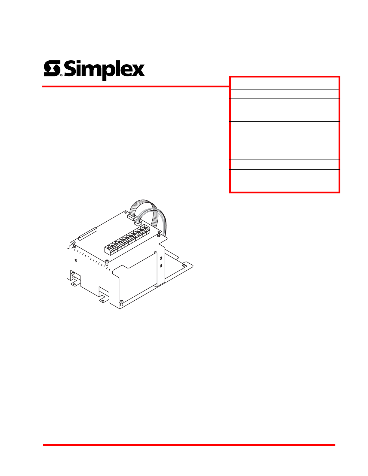
The 4008/4006-9801 Expansion Power Supply (EPS) is an option module
that installs into the main fire alarm control panel. The EPS provides two
additional NACs, and filtered/regulated 24 VDC, alarm power.
The 3 A alarm power may be split between the two NACs and the
0.5 A auxiliary 24 VDC power tap. Refer to the NAC ratings section of these
instructions for circuit loading restrictions. The expansion power supply is
mounted to the right of the main system board (MSB) at the bottom of the
chassis, and is connected by the installer via three separate harnesses.
One EPS per system is allowed.
Figure 1, below, is an illustration of the EPS assembly.
System
Compatibility
Operating
Temperature
Operating
Humidity
Dimensions
Current
Rating
AC Input
Voltage
Specifications
General
4006/4008 Fire Alarm System
0 to 49 degrees C
32 to 120 degrees F
Up to 93% relative humidity
(non condensing)
Mounting
Width = 4.38 in ( 1 1.2 cm)
Height = 7 in (17.8 cm)
Depth = 4 in (10.2 cm)
Power
2 A per NAC; 3 A.alarm power
@ 24 VDC
120 V, 60Hz, 2 A max
240 V, 50 Hz, 1.5 A max
Figure 1 The Expansion Power Supply
The EPS assembly is shipped with the following:
• EPS assembly (bracket with two PCBs)
• Screws/washers (441-002; qty: 2)
• AC harness (734-179): black/white leads
• Battery harness (734-180): red/black leads
• Data flex harness (166-438): flat cable
Note: This document contains instructions on installing the EPS into the fire
alarm control panel. For programming instructions, refer to the Front Panel
Installing, Operating, and Programming Instructions (579-704 for 4006, or
579-716 for 4008).
In this Document
Mounting.........................................2
Panel interconnections ...................3
NAC wiring......................................5
Auxiliary 24 V wiring .......................6
NAC ratings ....................................7
© 2004 Tyco Safety Products, Westminster, MA 01441 USA All specifications were current and are subject to change wit hout notice. PN: 579-707
Technical Manuals Online! - http://www.tech-man.com
Rev. A
Page 2
Expansion Power Supply (EPS) Installation Instructions
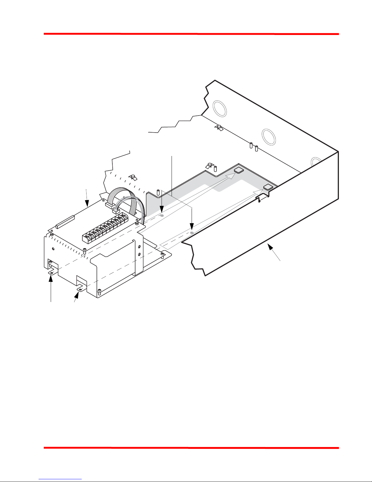
Mounting
Mount the EPS to the main annunciation cabinet as shown
in the figure below
Fasten the EPS to the cabinet with
two slotted torx screws (441-002).
EPS
Screwholes
MAIN
CABINET
Figure 2 Mounting the EPS
Technical Manuals Online! - http://www.tech-man.com
2
Page 3

Expansion Power Supply (EPS) Installation Instructions
Panel interconnections
Use the following steps and the figure on the next page to
connect the EPS to the Main System Board (MSB).
1. Remove AC and battery power from the panel. You
will be wiring to the AC line. Be sure the circuit
breaker is OFF and tagged.
2. You have the option of removing the Depleted Battery
Cutout jumper (R76) on the EPS. Removing the
jumper has the following effects:
- The system will NOT initiate an alarm if the first
alarm occurs after the depleted battery state has
been detected.
- The system will shut down 60 seconds after the
depleted battery condition is detected.
Remove the jumper if required. Note that there is a
corresponding option in the programmer that must be
set; see the Front Panel Installing, Operating, and
Programming Instructions (579-704 for 4006,
579-716 for 4008).
3. Connect the data flex harness (166-438) from J1 on
the EPS to
- J8 on the 4006-9801
- J3 on the 4008-9801
4. The AC harness (734-179) is used to connect AC
power from the MSB to the EPS.
- AC source is 120 VAC, 60 Hz (single phase) or
240 VAC (nominal), 50 Hz (single phase).
- Strip 3/8" insulation from the black and white
wires.
- Connect the black wire lead to the LEFT MSB
AC power terminal (TB4) marked “LINE.”
- Connect the white wire lead to the RIGHT MSB
AC power terminal (TB4) marked “NEUTRAL.”
- Connect the snap-on AC harness connector to P6
on the EPS.
5. Connect the battery harness (734-180) from P3 on the
EPS to the battery connector on the MSB (P13 on the
4006; P14 on the 4008). Do not connect the harness to
the batteries until you are ready to power up the
system. Connectors should be aligned such that:
- On P13 or P14 on the MSB, the red wire is on the
left and the black wire is on the right.
- On P3 on the EPS, the red wire is on the bottom
and the black wire is on top (closer to R76; see
the figure on the next page).
Technical Manuals Online! - http://www.tech-man.com
3
Page 4

Expansion Power Supply (EPS) Installation Instructions
MAIN SYSTEM BOARD
DEPLETED BATTERY
CUTOUT JUMPER
REMOVE POWER
FROM AC AND BATTERY
TERMINALS AND FROM
CIRCUIT BREAKER
BEFORE WIRING THE
EXPANSION POWER
SUPPLY.
R407 on 4008
R313 on 4006
TB4
EPS
+-
166-438 DATA FLEX
HARNESS
P14 on 4008
P13 on 4006
EPS
TOP BOARD
J1
734-180
BATTERY HARNESS
RED: LEFT ON P13/P14; BOTTOM
734-179
AC HARNESS
BLACK: LEFT ON TB4; RIGHT ON P6
WHITE: RIGHT ON TB4; LEFT ON P6
Figure 3 Interconnections between the MSB and EPS
J3 on 4008
J8 on 4006
ON P3
BLACK: RIGHT ON P13/P14;
TOP ON P3
DEPLETED BATTERY
CUTOUT JUMPER
R76
EPS
BOTTOM BOARD
(TINTED AREA = PORTION OF
BOTTOM BOARD OBSCURED
BY TOP OF ASSEMBLY)
P3
P6
Technical Manuals Online! - http://www.tech-man.com
4
Page 5

Expansion Power Supply (EPS) Installation Instructions
NAC wiring
MAIN CABINET
CLASS B WIRING:
route NAC
wiring upwards
MAIN
733-894
EOLR
SYSTEM
BOARD
• NAC wiring from the EPS is ro uted within th e
cabinet as shown above.
• NAC terminals accept 18 AWG to 12 AWG
wire. Larger wire reduces line loss and
allows longer wiring distance from the FACP
to the notification applia nces.
• Use a VOM to test conductors for grou nds
and stray voltages before connecti on to
appliances and panel.
• All wiring is supervised and Power Limited.
• Circuits must not be “T”-tapped.
• Terminate each Class B circuit with a
10 k, 0.5 W resistor (733-894). For Canadian
applications, mount the end-of-line resistor
to TEPG-US Model 431537 EOL Plate per
Standard
ULC-5524.
• Wire Class A (Style Z) NACs from “B+” and
“B-” to each appliance. No end-of-line is
needed for Class A. Connect wires fro m “+”
and “-” on the last appliance to “A+” and A-”
on the EPS.
• The 10 k, 0.5 W (brown/black/ orange)
resistor (factory installed) should remain
installed across “B+” and “B-” on unused
NACs to keep them in the "normal" state.
• Current rating: Each NAC supplies 2 A
(special application). EPS provides 3 A,
which is split between AUX 24 V and NAC
loads. Refer to the NAC ratings section of
these instructions for circuit loading
restrictions.
• Terminal designations are for the alarm state (+/-).
• If wiring is routed outside the bui lding, use of a listed secondary
protector is required. Use 2 081-9028 or 2081-9044. A protector
must be installed at each bu ildin g exi t/ent ra nce. Each20 81- 9028
adds 0.2 Ohms wiring resistance. 2081-9044 adds 6 Ohms
resistance.
• The wiring chart to the right gives the maximum distance for 0.25
A to 2 A loads.
For Class B, distance = panel terminals to the last appliance.
For Class A, distance = EPS terminals to the las t appliance and
back to the EPS terminals.
• When using non-addressable Series 4901, 4903, and 4904 twowire audible/visible applianc es , max i mum wi rin g capacitance is
0.22 uF. Determine wiring capacitance by adding wire-to-wire
capacitance plus wire-to-shield capacitance (if shield is used).
Multiply the result by the wire length in feet. Example: A 12 AWG
FPLR is rated at 100 pF/foot, with no shield. The 0.22 uF limit
allows a maximum length of 2,200 ft. Also check th e wiring
distance chart, right, to determine that the voltage drop will not
be excessive.
• Max. number of Smart Sync appliances = 2 A divided by the
current draw amperage of the appliances used.
EPS
CLASS A WIRING:
NAC +
NAC-
NAC +
NAC-
NAC +
B+ B-
TYPICAL AUDIBLE/VISIBLE APPLIANCES
B+ B- A+ A- A+ A-
TB1 ON
EXPANSION POWER SUPPLY
NAC3 NAC4
NAC-
NAC +
NAC-
NAC +
NAC-
NAC +
B+ B- A+ A-
TYPICAL AUDIBLE/VISIBLE APPLIANCES
B+ B- A+ A-
TB1 ON
EXPANSION POWER SUPPLY
NAC3 NAC4
Alarm
Current
(Amps)
Max. Distance from Panel to Last Device (Feet) Line
Resistance
18 AWG 16 AWG 14 AWG 12 AWG
(Ohms)
0.25 840 1335 2126 3382 12
0.50 420 667 1063 1691 6
0.75 280 445 709 1127 4
1.00 210 334 532 845 3
1.25 168 267 425 676 2.4
1.50 140 222 354 564 2
1.75 120 191 304 483 1.71
2.00 105 167 266 423 1.5
Chart allows for a drop of 3.4 V due to wire resistance. Wire resistance given is for
copper wire at 50° C (122° F).
Figure 4 NAC Wiring (Class A and B)
Technical Manuals Online! - http://www.tech-man.com
5
Page 6

Expansion Power Supply (EPS) Installation Instructions
Auxiliary 24 V wiring
4008
MAIN SYSTEM BOARD
4006
MAIN SYSTEM
BOARD
AUX 24 V 0.5 A MAX
FROM MSB
- +
AUX 24 V
0.5 A MAX.
- +
AUX 24 V 0.5 A MAX
FROM MSB
+ -
EXPANSION
POWER
SUPPLY
• Aux terminals accept 18 AWG to 12 AWG wire.
• Conductors must test free of all grounds and stray voltages before connection to appliances, devices, and panel.
• All wiring is supervised and Power Limited.
• Voltage rating (24 VDC special application): 1 V p-p ripple (maximum)
0.5 A maximum available aux 24 V from EPS
Additional 0.5 A maximum available from Main System Board (MSB) aux 24 V
3 A total available from MSB NACs and MSB aux 24 V.
3 A total available from EPS NACs and EPS aux 24 V.
• Compatible with Simplex 4098 Series Peripherals; 2098 Series Relay Modules; all Simplex 4090 Series IDNet
Peripherals; and 4610-9111 / 4606-9101 Annunciators.
• If wiring is routed outside the building, use of a listed secondary protector is required. Use 2081-9044or 2081-9028. A
protector must be installed at each building exit/entrance. Each 2081-9044 adds 6 Ohms resistance at 200 mA. Each
2081-9028 adds 0.2 Ohms wiring resistance, and is rated for more than the 0.5 A aux 24 V capacity.
• If the circuit is used to power the Model 4098-9682 Four-Wire Base, the auxiliary 24 V power must be routed through the
2098-9735 End-Of-Line Relay, as shown in Figure 6 (below).
Figure 5 Aux 24 V Wiring
24VDC
Power
IDC
LISTED
CONTROL
PAN E L
24VDC
TYPICAL 4-WIRE
DETECTOR
TYPICAL 4-WIRE ZONE 24VDC DEVICES
2098-9735
E.O.L. RELAY
RED
BLACK
(RELAY SHOWN
ENERGIZED)
YELLOW
YELLOW
END-OF-LINE DEVICE
SELECTED PER ZONE
CIRCUIT
Figure 6 2098-9735 End-Of-Line Relay
Technical Manuals Online! - http://www.tech-man.com
6
Page 7

Expansion Power Supply (EPS) Installation Instructions
NAC ratings
The panel is rated Special Application for 2 A maximum
per NAC with Simplex 4901 and 4906 TrueAlert MultiCandela Notification Appliances.
For all other UL Listed Notification Appliances, NACs are
rated Regulated 24 VDC at 1.5 A maximum each.
Maximum allowed strobe load on either the main or
Table 1 NAC Ratings
15Cd 30Cd 75Cd 110Cd
4906-
9101 0.060 33 0.094 21 0.186 10 0.252 7
9102 0.075 26 0.125 16 0.233 8 0.316 6
9103 0.060 33 0.094 21 0.186 10 0.252 7
9104 0.075 26 0.125 16 0.233 8 0.316 6
9127 0.075 26 0.116 17 0.221 9 0.285 7
9128 0.086 23 0.132 15 0.250 8 0.320 6
9129 0.075 26 0.116 17 0.221 9 0.285 7
Rated
Current
Max. # per
NAC
Rated
Current
Max. #
per NAC
expansion power supply is 1.35 A. The balance of the 3 A
capacity can be auxiliary loads or audible notification
appliances.
Synchronization of strobes across all NACs in a system is
UL Listed for the Simplex models noted in the table
below. See the table below for maximum number allowed
of each model appliance per NAC.
Rated
Current
Max. # per
NAC
Rated
Current
Max. # per
NAC
9130 0.086 23 0.132 15 0.250 8 0.320 6
9151 0.060 33 0.094 21 0.186 10 0.252 7
9154 0.075 26 0.125 16 0.233 8 0.316 6
9153 0.060 33 0.094 21 0.186 10 0.252 7
All other regulated 24 VDC synchronized notification
appliances require the use of their associated Listed
external synchronization module. Notification Circuit
rating is 1.5 A maximum, 1.35 A maximum strobe load
per power supply.
Technical Manuals Online! - http://www.tech-man.com
7
Page 8

Expansion Power Supply (EPS) Installation Instructions
DO NOT INSTALL ANY PRODUCT THAT APPEARS DAMAGED. Upon unpacking your product, inspect the contents of the carton for
shipping damage. If damage is apparent, immediately file a claim with the carrier and notify the manufacturer.
ELECTRICAL HAZARD - Disconnect electrical power when making any internal adjustments or repairs. Servicing should be performed
by qualified personnel.
STATIC HAZARD - Static electricity can damage components. Therefore, handle as follows:
1. Ground yourself before opening or installing components.
2. Keep uninstalled components wrapped in anti-static material at all times.
Warning: Changes or modifications to this unit not expressly approved by the party responsible for compliance could void
the user's authority to operate equipment.
NOTE: This equipment has been tested and found to comply with the limits for a Class A digital device, pursuant to Part 15 of
the FCC Rules. These limits are designed to provide reasonable protection against harmful interference when the equipment
is operated in a commercial environment. This equipment generates, uses, and can radiate radio frequency energy and, if not
installed and used in accordance with the instruction manual, may cause harmful interference to radio communications.
Operation of this equipment in a residential area is likely to cause harmful interference in which case the user will be required
to correct the interference at his own expense.
Technical Manuals Online! - http://www.tech-man.com
8
 Loading...