

Page 1

Technical Manuals Online! - http://www.tech-man.com
Page 2

Copyright and Trademarks
© 2005 Tyco Safety Products Westminster, Westminster MA 01441-0001 USA
Printed in the United States of America.
Information in this document is subject to change without notice. No part of this document may be reproduced or transmitted
in any form or by any means, electronic or mechanical, for any purpose, without the express written consent of Tyco Safety
Products.
Tyco, Simplex, the Simplex logo, IDNet, SmartSync and WALKTEST are registered trademarks of Tyco International Services AG or its affiliates in the US and/or other countries.
TrueAlarm analog smoke detection is protected by one or more of the following U.S. Patents: 5,155,468; 5,173,683;
5,543,777. IDNet addressable communications are protected by U.S. Patent No. 4,796,025. IDNet duplicate device detection
is protected under U.S. Patent No. 6,034,601. WALKTEST system test is protected under US Patent No. 4,725,818. SmartSync horn/strobe operation is protected under U.S. Patent No. 6,281,789. Two wire synchronization circuit operation is protected by U.S. patent No. 5,559,492.
Technical Manuals Online! - http://www.tech-man.com
Page 3

FCC Information
This equipment complies with Part 68 of the FCC rules and the requirements adopted by the ACTA. On the door of this equipment is a label that contains, among other information, the following product identifier: US:5QWAL01B4008. If requested,
the number must be provided to the telephone company.
In the event of equipment malfunction, all repairs should be performed by an authorized agent. It is the responsibility of users
requiring service to report the need for service to our company or to one of our authorized agents. Service can be arranged
through our office at:
Tyco Safety Products
91 Technology Drive
Westminster, MA 01473
978-731-2500
The Ringer Equivalence Number (REN), which is 01 for the DACT installed in this panel, is used to determine the number of
devices that may be connected to a telephone line. Excessive RENs on a telephone line may result in the devices not ringing in
response to an incoming call. In most, but not all areas, the sum of RENs should not exceed five (5.0). To be certain of the
number of devices that may be connected to a line, as determined by the total number of RENs, contact the local telephone
company. For products approved after July 23, 2001, the REN is part of the product identifier, which uses the format
US:AAAEQ##TXXXX. The digits represented by ## are the REN without a decimal point (e.g. 01 is a REN of 0.1).
If the DACT causes harm to the telephone network, the telephone company will notify you in advance that temporary discontinuance of service may be required. But if advance notice isn’t practical, the telephone company will notify you as soon as
possible. If your service is discontinued, you will be advised of your right to file a complaint with the FCC.
The telephone company may make changes to its facilities, equipment, operations, or procedures that could affect the operation of the equipment. If this happens the telephone company will provide advance notice in order for you to make the necessary modifications to maintain uninterrupted service.
If trouble is experienced with the DACT, please contact Tyco Safety Products at the location identified above. If the equipment
is causing harm to the telephone network, the telephone company may request that you disconnect the equipment until the
problem is resolved.
Alarm Dialing Equipment
This equipment must be able to seize the telephone line and place a call in an emergency situation. It must be able to do this
even if other equipment (telephone, answering system, computer modem, etc.) already has the telephone line in use. To do so,
the DACT must be electrically in series with and ahead of all other equipment attached to the same telephone line. Proper
installation is depicted in the figure below. If you have any questions concerning these instructions you should consult your
telephone company or a qualified installer about connecting the alarm dialing equipment for you.
Technical Manuals Online! - http://www.tech-man.com
Page 4
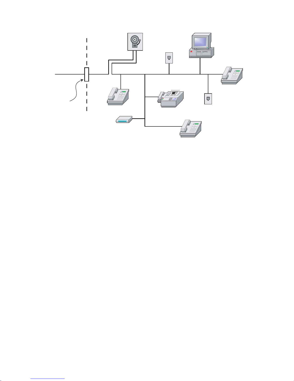
Connectors for the DACT are terminal blocks on the DACT module. Refer to DACT Wiring in Chapter 2 of this manual for
Telephone
Line
Network
Demarcation
Point
Unused
RJ-11 Jack
Network
Service
Provider's
Facilities
DACT
Computer
Unused
RJ-11 Jack
Fax
Telephone
Telephone
Telephone
Answering
System
specific DACT wiring instructions.
Technical Manuals Online! - http://www.tech-man.com
Page 5

Cautions and Warnings
READ AND SAVE THESE INSTRUCTIONS. Follow the instructions in this installation manual. These instructions must be
followed to avoid damage to this product and associated equipment. Product operation and reliability depends upon proper
installation.
DO NOT INSTALL ANY PRODUCT THAT APPEARS DAMAGED. Upon unpacking your product, inspect the contents of
the carton for shipping damage. If damage is apparent, immediately file a claim with the carrier and notify Simplex.
ELECTRICAL HAZARD - Disconnect electrical field power when making any internal adjustments or repairs. Servicing
should be performed by qualified Technical Representatives.
STATIC HAZARD - Static electricity can damage components. Therefore, handle as follows:
• Ground yourself before opening or installing components.
• Prior to installation, keep components wrapped in anti-static material at all times.
RADIO FREQUENCY ENERGY - This equipment generates, uses, and can radiate radio frequency energy and if not installed
and used in accordance with the instruction manual, can cause interference to radio communications. It has been tested and
found to comply with the limits for a Class A computing device pursuant to Subpart J of Part 15 of FCC Rules, which are
designed to provide reasonable protection against such interference when operated in a commercial environment. Operation of
this equipment in a residential area may cause interference in which case the user at his own expense will be required to take
whatever measures may be required to correct the interference.
SYSTEM REACCEPTANCE TEST AFTER SOFTWARE CHANGES - To ensure proper system operation, this product must
be tested in accordance with NFPA72 after any programming operation or change in site-specific software. Reacceptance testing is required after any change, addition or deletion of system components, or after any modification, repair or adjustment to
system hardware or wiring.
All components, circuits, system operations, or software functions known to be affected by a change must be 100% tested. In
addition, to ensure that other operations are not inadvertently affected, at least 10% of initiating devices that are not directly
affected by the change, up to a maximum of 50 devices, must also be tested and proper system operation verified.
Technical Manuals Online! - http://www.tech-man.com
Page 6

Technical Manuals Online! - http://www.tech-man.com
Page 7

Table of Contents
Overview ................................................................................................. 1-1
Main System Board.......................................................................................................................... 1-1
Power supply ................................................................................................................................... 1-2
Environmental Specifications .................................................................................................................. 1-2
Option Modules ....................................................................................................................................... 1-2
4006-9801 Expansion Power Supply (EPS) .................................................................................... 1-2
4006-9802 Expansion IDC Module (XIM) ....................................................................................... 1-2
4006-9805 and 4006-9806 City Circuit Cards.................................................................................. 1-2
4006-9803 Expansion Relay Module ............................................................................................... 1-2
Annunciator Modules ....................................................................................................................... 1-2
4009-9201/4009-9202CA NAC Extender ................................................................................................ 1-2
Initiating Devices ..................................................................................................................................... 1-3
Photoelectric Smoke Detector ......................................................................................................... 1-3
Heat Detector ................................................................................................................................... 1-3
Combination Photo/Heat Detector ................................................................................................... 1-3
Detector Bases ................................................................................................................................ 1-3
User Interface .......................................................................................................................................... 1-3
Logging In and Out .................................................................................................................................. 1-5
Login/Logout Procedure................................................................................................................... 1-5
Overview - Programming a Job ............................................................................................................... 1-5
Alarm Groups ................................................................................................................................... 1-6
Installation and System
Checkout ................................................................................................. 2-1
Back Box Mounting.................................................................................................................................. 2-1
Removing Electronics Assembly...................................................................................................... 2-1
Conduit Entrances ........................................................................................................................... 2-1
Guidelines for Locating Backbox ..................................................................................................... 2-2
Surface Mounting ............................................................................................................................. 2-2
Semi-Flush Mounting ....................................................................................................................... 2-2
General Wiring Guidelines....................................................................................................................... 2-2
IDC Wiring ............................................................................................................................................... 2-3
Wiring 4098-9682 Four-Wire Base .................................................................................................. 2-4
NAC Wiring.............................................................................................................................................. 2-5
Technical Manuals Online! - http://www.tech-man.com
Page 8

General Wiring Notes ....................................................................................................................... 2-5
Location of Expansion Power Supply NACs (If Used) ...................................................................... 2-5
NAC ratings ...................................................................................................................................... 2-7
Auxiliary Relay Wiring ..............................................................................................................................2-8
DACT........................................................................................................................................................2-9
Remote Annunciator Wiring ...................................................................................................................2-11
City Connect Module Wiring ...................................................................................................................2-12
Auxiliary 24 V Wiring ..............................................................................................................................2-13
Connecting to AC Power ........................................................................................................................2-14
Wiring Battery Power..............................................................................................................................2-15
Depleted Battery Cutout .........................................................................................................................2-16
Safety Ground/Ferrite Bead ...................................................................................................................2-16
System Powerup and Checkout .............................................................................................................2-16
Acceptance Testing ........................................................................................................................ 2-16
Testing Circuit Supervision ............................................................................................................. 2-16
Replacing Lithium Battery ......................................................................................................................2-17
Periodic Testing and Maintenance .........................................................................................................2-17
Smoke Detector Tests .................................................................................................................... 2-17
Battery Tests................................................................................................................................... 2-17
Programming IDCs, NACs, and AUX Relays ....................................... 3-1
Default General Alarm Programming .......................................................................................................3-2
Accessing Menus .....................................................................................................................................3-2
Editing IDCs .............................................................................................................................................3-2
Setting IDC Function Type................................................................................................................ 3-2
Entering Labels ................................................................................................................................. 3-4
Editing Alarm Groups........................................................................................................................ 3-5
Programming NACs .................................................................................................................................3-5
Setting NAC Function Type .............................................................................................................. 3-5
Editing Point Label ............................................................................................................................ 3-7
Editing Alarm Groups........................................................................................................................ 3-7
Programming AUX Relays .......................................................................................................................3-8
Editing Point Label ............................................................................................................................ 3-9
Clear Point Label .............................................................................................................................. 3-9
Saving Changes .......................................................................................................................................3-9
Programming the DACT ........................................................................ 4-1
Accessing DACT Menu ............................................................................................................................4-1
Programming DACT Options....................................................................................................................4-2
Enabling/Disabling DACT ................................................................................................................. 4-2
Setting Primary Phone Number ........................................................................................................ 4-2
Setting Primary Account Number...................................................................................................... 4-3
Setting Secondary Phone Number ................................................................................................... 4-3
Setting Secondary Account Number................................................................................................. 4-3
Setting Dialing Mode......................................................................................................................... 4-3
Technical Manuals Online! - http://www.tech-man.com
Page 9

Setting Pulse Rate ............................................................................................................................ 4-3
Setting Pulse Frequency................................................................................................................... 4-4
Reporting Format .............................................................................................................................. 4-4
AC Fail Delay .................................................................................................................................... 4-4
Test Report Time .............................................................................................................................. 4-5
Programming Contact ID (CID) Points .....................................................................................................4-5
Programming Event Codes ......................................................................................................................4-6
Saving Changes .......................................................................................................................................4-6
Programming Annunciator LEDs ......................................................... 5-1
Adding an Annunciator .............................................................................................................................5-2
Automatically Adding Annunciator Cards.......................................................................................... 5-2
Manually Adding an Annunciator Module ......................................................................................... 5-2
Accessing Annunciator Menus .................................................................................................................5-2
Programming LEDs Located on Zone Annunciator and Remote LED/Switch Modules ...........................5-3
Mapping LEDs to Software Points .................................................................................................... 5-3
Programming Overview .................................................................................................................... 5-3
Default Programming ........................................................................................................................ 5-3
Programming the LED’s Mode and Reference Point ........................................................................ 5-4
Programming Panel LEDs........................................................................................................................5-6
Setting LED Color ............................................................................................................................. 5-6
Setting LED Mode and Reference Point ........................................................................................... 5-6
Common LED Applications ......................................................................................................................5-7
Saving Changes .......................................................................................................................................5-7
Programming System Options ............................................................. 6-1
Accessing System Options Menu.............................................................................................................6-1
Programming Options ..............................................................................................................................6-1
Saving Changes .......................................................................................................................................6-4
Operating ................................................................................................ 7-1
Normal Operation .....................................................................................................................................7-1
Lamp Test ................................................................................................................................................7-1
Abnormal Conditions ................................................................................................................................7-1
Silencing Alarms.......................................................................................................................................7-2
System Reset ...........................................................................................................................................7-2
Viewing/Clearing Historical Logs ..............................................................................................................7-2
Viewing Logs .................................................................................................................................... 7-2
Clearing Logs.................................................................................................................................... 7-3
Viewing and Controlling Points.................................................................................................................7-3
Viewing Point Information ................................................................................................................. 7-3
Manually Activating a NAC/Relay.............................................................................................................7-4
Enabling or Disabling Points ....................................................................................................................7-4
Technical Manuals Online! - http://www.tech-man.com
Page 10

Control Functions .....................................................................................................................................7-4
Setting the Time and Date........................................................................................................................7-5
Reports.....................................................................................................................................................7-5
Diagnostics...............................................................................................................................................7-5
WalkTest ..................................................................................................................................................7-6
Setting WalkTest Options ................................................................................................................. 7-6
Advanced Operations...............................................................................................................................7-7
Upload/Download ............................................................................................................................. 7-7
Restarting the CPU ........................................................................................................................... 7-7
Viewing Software Revision Number and Job Info............................................................................. 7-7
Appendix A. Battery Standby Calculations
Current Draw for System Components ................................................................................................... A-1
Appendix B. Contact ID Default Values
Technical Manuals Online! - http://www.tech-man.com
Page 11

Technical Manuals Online! - http://www.tech-man.com
Page 12

Technical Manuals Online! - http://www.tech-man.com
Page 13

Chapter 1. Overview
This publication describes how to install, configure, operate, program,
and test an 4006-9101 and 4006-9121 (includes door-mounted annunciator) Fire Alarm Control Panel (FACP). In cases where the installation,
wiring, or programming procedure is identical for both panels, the term
4006 is used. If the procedure applies only to a specific panel, the complete product name (i.e., 4006-9121 is used).
The 4006 is a conventional fire alarm control panel. The base system
includes five Class B Initiating Device Circuits (IDCs), which may be
wired as Class A circuits with the addition of an optional Class A module. The base system also includes two Notification Appliance Circuits
(NACs), which may be wired class A or class B. A built-in DACT provides a means for remote station or central station monitoring.
The 4006 provides audible and visible indications during alarm, supervisory, or trouble conditions. Should any of these conditions occur, the
system activates the applicable notification appliances, LEDs, and the
panel tone-alert. The indications continue until an operator acknowledges the condition.
Main System Board
The 4006 base system includes the Main System Board (MSB) mounted
in a steel enclosure with locking door.
In This Chapter
Environmental Specifications . . . . . . . . . . . . . .1-2
Option Modules . . . . . . . . . . . . . . . . . . . . . . . . 1-2
4009-9201/4009-9202CA NAC Extender. . . . . 1-2
Initiating Devices . . . . . . . . . . . . . . . . . . . . . . . 1-3
User Interface. . . . . . . . . . . . . . . . . . . . . . . . . .1-3
Logging In and Out. . . . . . . . . . . . . . . . . . . . . .1-5
Overview - Programming a Job . . . . . . . . . . . .1-5
The MSB contains everything needed for a UL-listed fire alarm system
on one board. It consists of:
• System power supply (3A); 24V filtered
• Five IDCs (Class B)
• Two, 2A Notification Appliance Circuits (Class A or B)
• DACT
• Two auxiliary relay circuits
• One auxiliary power tap
• 2x20 backlit LCD, LEDs and keypad
• Service Port
• Expansion power supply connection
• Expansion IDC connection
• Expansion port for Class A IDC adapter connection
• Connection for interface to optional city card
• Communication channel for remote annunciators
• Battery-backed, non-volatile memory preserves logs, time/date
information, and disabled points on AC loss.
Technical Manuals Online! - http://www.tech-man.com
1-1
Page 14

Chapter 1. Overview
Power supply
• 120 VAC, 60 Hz, 4A; 240V, 50 Hz, 3A
• 24 VDC (filtered) 3A alarm power
• 24 VDC, ½A auxiliary power
• Battery charger up to 25 Ah batteries per UL864; temperature compensated. Recharge 12.7Ah batteries per
ULC-S527.
Note: The 4006 back box can accommodate up to
12.7 Ah batteries.
Environmental Specifications
The panel operates normally with ambient temperatures
from 32° F to 120° F (0° C to 49° C), inclusive.
The panel operates normally under non-condensing humidity conditions up to 93% relative humidity at 90° F (32° C).
Option Modules
The following lists all of the option modules for the 4006.
Refer to the individual instructions that accompany each
module for more information. Refer to the label inside the
door of the 4006 for the placement of optional modules.
4006-9801 Expansion Power Supply (EPS)
When additional notification appliance circuits are required,
an expansion power supply may be added. The expansion
power supply provides two additional 2A NACs, and filtered/regulated 24 VDC, 3A power. The expansion power
supply is mounted to the right of the MSB at the bottom of
the chassis. It connects to the MSB with a ribbon harness.
The 3A alarm power of the EPS may be split between the 2
NACs and the 1/2A Aux. 24V power tap. One EPS per system is allowed.
4006-9802 Expansion IDC Module (XIM)
This module mounts to the right of the MSB. It includes five
Class B Initiating Device Circuits, and a mounting point for
the optional IDC Class A adapter module.
4006-9805 and 4006-9806 City Circuit Cards
The city circuit card connects to the MSB with a ribbon harness to provide connections to either Remote Station
(reverse polarity), or Municipal Master (local energy)
receiving units (selectable). The card has two circuits - circuit 1 reports alarm or alarm/trouble events (Remote Station
only) and circuit 2 can be configured to report trouble events
or supervisory events. In the event of a CPU failure, a city
card configured for a trouble output sends a trouble to the
city circuit. The card is mounted to the right of the MSB at
the top of the chassis. The 4006-9805 and 4006-9806 city
cards are identical except that the 4006-9805 provides hardware disconnect switches for each circuit. One City Circuit
Card per system is allowed.
4006-9803 Expansion Relay Module
The Expansion Relay Module (ERM) includes 10 relays.
The relays may be programmed for per-zone operation, one
relay per IDC, or as desired. For example, it is possible to
program any relay for general alarm, trouble or supervisory
conditions. Normally Open or Normally Closed contact
operation is selected by shunt jumper placement. Contacts
are rated for 2A, 30VDC, 0.35 power factor.
Annunciator Modules
The 4006 supports the following annunciator modules. A
total of four annunciators may be added to the system, one of
which can be located in the panel (the Local Zone LED
module).
• Local Zone LED Module. The local Zone LED
Modules provides 24 LEDs for visible zone alarm and
trouble indication. (The Local Zone LED module,
which mounts on the front of the panel, is standard for
ULC-S527 compliant systems.) There are 10 Red and
14 Yellow LEDs. This provides a red alarm and yellow
trouble LED for each of 10 initiating device circuits.
This module also provides 4 Yellow LEDs, one for each
of 4 NACs. The LEDs are programmable, and can be
used for other functions as appropriate per application.
• 4610-9111 Remote LED/Switch Annunciator.
This annunciator provides the following:
- 10 programmable red LEDs (default programming
tracks alarm state of IDC1-IDC10)
- 6 programmable yellow LEDs (no default operation)
- Green “power on” LED
- Yellow “Alarm Silenced” LED
- Yellow “Trouble”
- Yellow “Comm Loss” LED
- Tone-Alert
- Switches for ACK, Alarm Silence, System Reset,
and Lamp Test
- Key switch to enable switch functions
4009-9201/4009-9202CA NAC
Extender
The 4009-9201/4009-9202CA (Canadian) Notification
Appliance Circuit (NAC) Extenders are self-contained
Technical Manuals Online! - http://www.tech-man.com
1-2
Page 15
Chapter 1. Overview
adjunct panels for use with 4006 Fire Alarm Control Panels
(FACPs).
The base version of the NAC Extender is a single-board system consisting of four NACs, a power supply and charger,
and two conventional NAC inputs that connect to the host
panel for hardwired control of the NAC extender.
Option cards are available to provide the following additional capabilities:
• 4009-9808 Class A Adapter Option Card -- allows fault
tolerance in the case of open circuit wiring faults on the
NACs.
• 4009-9807 NAC Option Card -- adds four conventional
Notification Appliance Circuits.
Initiating Devices
The 4006 is compatible with the following conventional initiating devices.
Photoelectric Smoke Detector
Photoelectric smoke detectors detect smoke by means of
optical sensing technology.
• 4098-9601/4098-9601C: Standard Sensitivity (2.8%/
foot) Photoelectric Smoke Detector
• 4098-9605: Special Sensitivity (3.5%/foot) Photoelectric Smoke Detector
Heat Detector
Four models of conventional electronic heat detector are
available:
• 4098-9612/4098-9612C: 135°F Fixed Temperature
Heat Detector
• 4098-9613/4098-9613C: 135°F Fixed Temperature
Heat Detector w/ rate of rise detection
• 4098-9614/4098-9614C: 200°F Fixed Temperature
Heat Detector
• 4098-9615/4098-9615C : 200°F Fixed Temperature
Heat Detector w/ rate of rise detection
• Fixed temperature trip point: 135°F
Rate of Rise trigger: 15°F-25°F per minute only at temperatures of 90°F or greater
Detector Bases
The detectors described above may be installed in the following detector bases:
• 4098-9788/4098-9788C: Two-wire detector base with
remote LED connection.
• 4098-9683/4098-9683C: Two wire detector base with
auxiliary relay (limit 1 per IDC).
• 4098-9684/4098-9684C: Two wire detector base with
alarm LED output. For use with 4098-961x series heat
detectors only.
• 4098-9682/4098-9682C: Four wire detector base with
auxiliary alarm relay .
Each of the smoke detectors includes an output for a remote
alarm LED. Base 4098-9684 is required for remote LED
control with 4098-9612 through 4098-9615 electronic heat
detectors.
Maximum of 30 total bases per IDC, except for 4098-9683
(limit one per IDC).
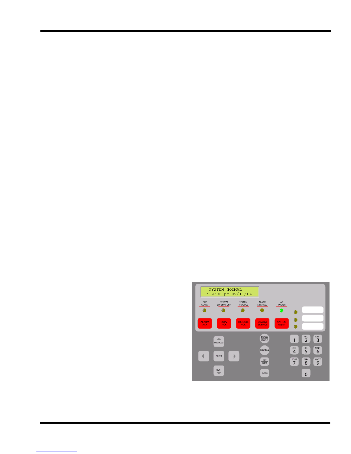
User Interface
The user interface consists of control keys, LEDs, a 2-line
by 20-character backlit LCD, and a sounder mounted in the
control panel. The purpose of the Operator and Menu keys is
listed below.
The rate of rise trigger is 15°F-25°F per minute.
Combination Photo/Heat Detector
The combination photo/heat detector ( 4098-9602/40989602C) is a combination photoelectric detector and thermal
detector in one head. This detector correlates smoke and
thermal activity to provide earliest alarm initiation.
• Smoke detector sensitivity: 2.8% /ft. obscuration
Technical Manuals Online! - http://www.tech-man.com
Figure 1-1 User Interface
1-3
Page 16

Chapter 1. Overview
Table 1-1 Operator Keys (Continued)
Table 1-1 Operator Keys
Key Function
Acknowledges any unacknowledged fire
ALARM
ACK
SUPV
ACK
TROUBLE
ACK
ALARM
SILENCE
SYSTEM
RESET
MENU
alarms in the system, and scrolls
through the alarms in the active Alarm
List.
Acknowledges any unacknowledged
supervisories in the system, and scrolls
through the supervisory conditions in the
active Supervisory List.
Acknowledges any unacknowledged
troubles in the system, and scrolls
through the trouble conditions in the
active Trouble List.
Silences any silenceable output types
(generally all audible notification appliances).
Allows the operator to reset all alarm
notification appliances and controls,
remove alarms from the Alarm List,
silence all silenceable outputs, reset
detectors, and return the system to a
normal state (provided that no alarm,
supervisory or trouble conditions are
present). The display indicates that a
reset is in progress and whether or not a
reset completes successfully.
Pressing the <SYSTEM RESET> key
will only attempt to return the system to
a normal, non-alarm state. All outputs
that were activated by the alarm will
remain active until all alarm inputs have
been restored and the reset was able to
successfully complete.
An open circuit fault on a Class A NAC
does not require a System Reset to
restore to normal.
Open circuit faults on the optional City
Connect module are cleared with a system reset after the circuit has been
repaired.
The Menu key always brings you to the
top of the main menu structure unless
you are in the Programming menu.
Key Function
The Function Menu is displayed when
the <Function> key is pressed at the
high-level status screen. Use the <Previ-
FUNCTION
DISABLE/
ENABLE
EXIT/
CLEAR
ENTER
RIGHT/LEFT
ARROWS
PREVIOUS/
NEXT
ous> and <Next> keys to scroll through
the list of functions. The function key
provides access to commonly used control and display functions.
The <Disable/Enable> key allows the
operator to quickly disable or enable any
point that is currently displayed. This key
is passcode protected. A confirmation
screen is displayed requesting <Enter>
be pressed before the actual enable or
disable is performed.
The <Exit/Clear> key is used to back out
of menus or displays and return to the
top-level menu structure. Where possible, the <Exit/Clear> key backs out one
level at a time. There are cases, however, that the Exit/Clear key will return
the operator directly to the top-level
menu.
The <Enter> key is used to confirm
selections. When pressed, this key provides additional information about the
point shown on the display. In a programming screen, pressing <Enter>
indicates that the information on the display is correct and can be accepted. The
<Enter> key is used in various other
places within the menu structure, always
for this same type of operation.
The right and left arrows are used in
screens with multiple choices. The keys
advance the focus (square brackets [ ])
from field to field.
The Previous & Next keys are used to
scroll through the system lists, historical
log, point database, etc. The <Next> key
selects the next display screen in
sequence, and the <Previous> key
selects the previous screen. These keys
are also used to view additional information about abnormal points or in viewing
historical logs.
Technical Manuals Online! - http://www.tech-man.com
1-4
Page 17

Chapter 1. Overview
Logging In and Out
Certain operator functions are passcode-protected at different levels. This section describes the operator functions,
their default access level, and the login/logout procedure.
Table 1-2 Access Levels and Features
Access
Level
Acknowledge, Silence, System Reset,
1
2
Passcode =
2000
3
Passcode =
3000
4
Passcode =
4000
View Historical Logs,
View Point Information, Lamp Test
All Level 1 operations, plus:
Set Time/Date, Point Control,
Enable/Disable points
All Level 1 & 2 operations, plus:
Clear Historical Logs,
Clear Verification Tallies
Custom Label editing
WALKTEST
All Level 1, 2, & 3 operations, plus:
Programming,
Upload/Download
Login/Logout Procedure
To perform any of the functions protected at Level 2 or
above, you must login to the panel using a passcode. After
completing a task at a certain access level, you should then
logout to return the access level to Level 1 to prevent unauthorized operation. When logged in at Level 2 or above and
no panel keys are pressed for more than 10 minutes, the
panel automatically returns the system to Level 1.
All passcodes consist of a 4-digit number. Logging in at
Level 4 causes a Service Mode trouble that may only be
cleared by restarting the panel.
To login, perform the following steps:
1. Obtain the passcode information for the desired level.
2. Press <MENU>
3. Press <NEXT> until [Login/Logout] is displayed, then
press <ENTER>. A prompt similar to the following
appears.
Access: Level 1
<ENTER>=[Login]
Operation
Access: Level 1
Passcode: [0]
5. Use the Keypad to enter the appropriate passcode.
6. When the passcode is correct, press the <ENTER> key
to login.
A “Login Accepted” message, which indicates your current
access level, is displayed briefly upon a successful login
attempt. If you did not enter the appropriate Login passcode,
a “Login Invalid” screen appears.
To logout, perform steps 1-4 above, but select Logout
instead of Login.
Overview - Programming a Job
A job refers to the file containing all of the panel’s programming information. This manual describes the process
required to create a job from the front panel of the system.
Creating a job involves:
• Setting the attributes of each IDC, NAC, and AUX
relay, including:
- Function Type. Determines the way in which the
IDC, NAC, or relay operates (i.e., fire point, trouble
point, on til silence, etc.)
- Custom Label. This is a 20-character label that
describes each zone, NAC, or relay.
- Alarm Group. Allows inputs and outputs to be
associated into groups to implement selective signaling applications. See “Alarm Groups” below.
• Defining the attributes (phone numbers, account numbers, reporting format, etc.) of the panel’s Digital Alarm
Communicator Transmitter (DACT). If the DACT will
not be used, programming consists of disabling the
DACT.
• Programming the operation of the LEDs contained on
the panel and connected annunciators. Programming an
annunciator consists of identifying the point being monitored by the LED and the mode (i.e., fire alarm, trouble, etc.) that will trigger the LED to illuminate.
• Setting values for the panel’s system options, which are
pre-defined modes of operation with a range of settings
from which to choose. System Options define global
operations such as the time and date format, door drop
timers, and whether the city circuit is enabled, etc.
4. Press <NEXT> until [Login] is displayed, then press
<ENTER>. A prompt similar to the following appears.
Technical Manuals Online! - http://www.tech-man.com
1-5
Page 18

Chapter 1. Overview
Alarm Groups
Alarm groups allow you to implement basic selective signalling applications. As you program input (zone of smoke
detectors) and output points (NAC or relay), you are given
the opportunity to associate the point with an alarm group
number. The number can range from 1-100 and each point
can be in up to three alarm groups. When programming is
complete, an initiating device can only trigger the output
devices (relays, NACs) that share its alarm group(s).
Technical Manuals Online! - http://www.tech-man.com
1-6
Page 19
TB1 TB2 TB3
Battery
AC Voltage
Connection
Battery
Connection
Battery
City Connect
Module
Expansion
Power Supply
DACT
Chapter 2. Installation and System
Checkout
Back Box Mounting
The back box can be surface-mounted or semi-flush mounted to the
wall. Use separate conduit entrances for power-limited and non-power
limited wiring.
AC supply, battery supply, and City Connect wiring are all non-power
limited wiring.
Removing Electronics Assembly
Use either a #6 Torx or a slot-head screwdriver to remove the four
screws that secure the electronics assembly to the back box.
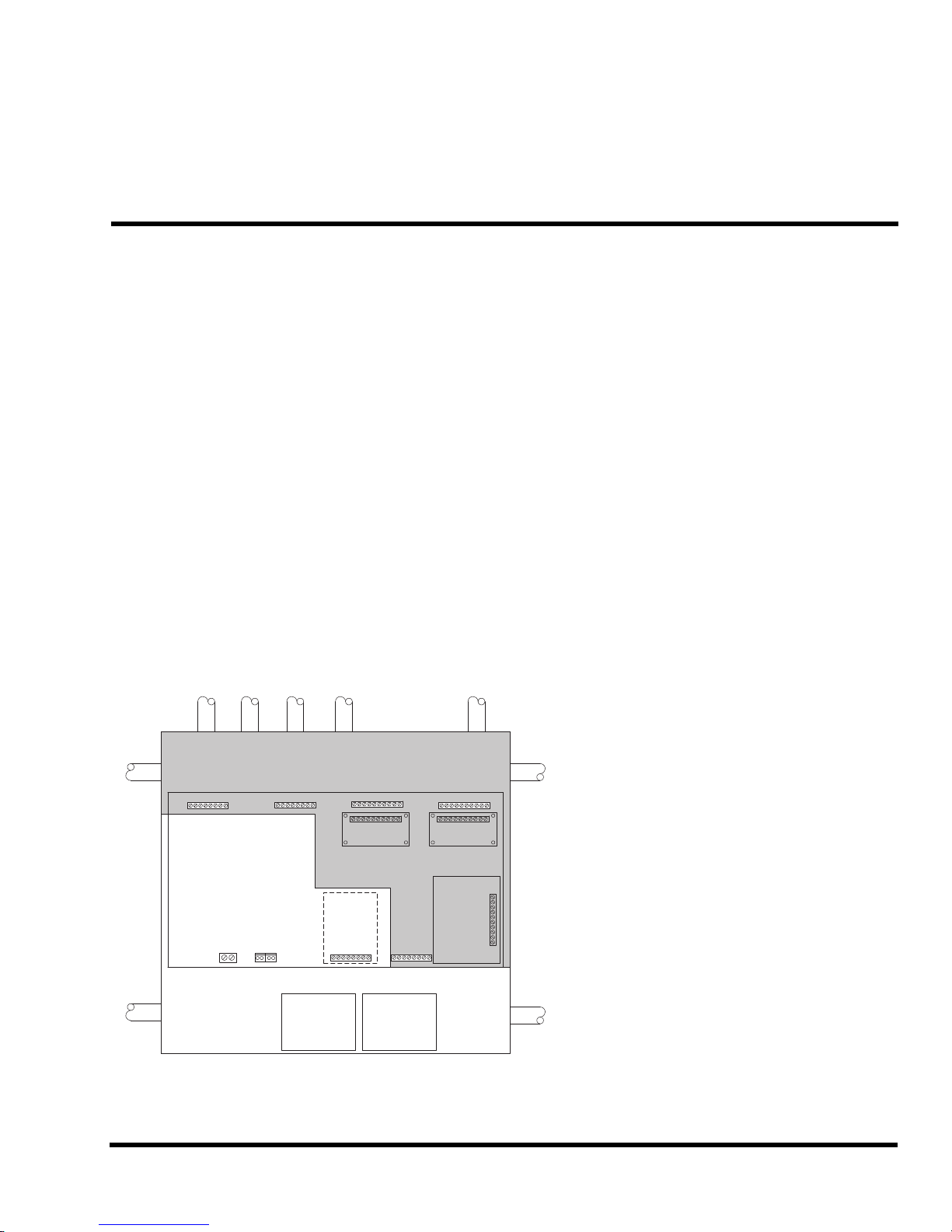
Conduit Entrances
• Nine knockouts are provided for conduit connection. Refer to Figure 2-1 for knockout locations.
• Power limited wiring must be located only in the shaded area of
the cabinet.
• AC power (non-power limited) wiring must be run in separate conduit from all other wiring, as shown in the figure below. Non-
power limited wiring must be separated from power limited
wiring by a minimum of 1/4”.
In This Chapter
Back Box Mounting . . . . . . . . . . . . . . . . . . . . 2-1
General Wiring Guidelines . . . . . . . . . . . . . . . 2-2
IDC Wiring . . . . . . . . . . . . . . . . . . . . . . . . . . . 2-3
NAC Wiring . . . . . . . . . . . . . . . . . . . . . . . . . . 2-5
Auxiliary Relay Wiring . . . . . . . . . . . . . . . . . . 2-8
DACT . . . . . . . . . . . . . . . . . . . . . . . . . . . . . . . 2-9
Remote Annunciator Wiring . . . . . . . . . . . . . 2-11
City Connect Module Wiring. . . . . . . . . . . . . 2-12
Auxiliary 24 V Wiring . . . . . . . . . . . . . . . . . . 2-13
Connecting to AC Power . . . . . . . . . . . . . . . 2-14
Wiring Battery Power . . . . . . . . . . . . . . . . . . 2-15
Depleted Battery Cutout. . . . . . . . . . . . . . . . 2-16
Safety Ground/Ferrite Bead . . . . . . . . . . . . . 2-16
System Powerup and Checkout. . . . . . . . . . 2-16
Replacing Lithium Battery . . . . . . . . . . . . . . 2-17
Periodic Testing and Maintenance . . . . . . . . 2-17
Figure 2-1 Power-Limited (Shaded) and
Non-Power Limited Wiring Areas
Technical Manuals Online! - http://www.tech-man.com
2-1
Page 20
Chapter 2. Installation and System Checkout
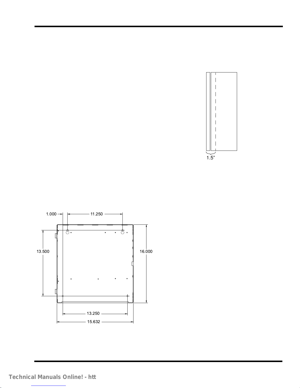
1.000 11.250
13.500
13.250
15.632
16.000
1.5”
• All Aux Relay loads must be powered from the AUX
power circuit or from a regulated, 24 VDC, power-limited power supply that is UL-listed for fire protective
signaling service.
Guidelines for Locating Backbox
Always refer to engineering drawings/site installation plans
before beginning installation. The system is designed to
operate in a typical commercial environment. Choose a site
for each backbox that is:
• Well-ventilated, clean, and dust-free.
• Located near a dedicated AC individual branch circuit
with Earth ground (to maintain a consistent supply voltage).
• Away from sources of heat, including direct sunlight.
• Away from sources of vibration or physical shock.
• Away from sources of Radio Frequency Interference
(RFI), such as a radio transceiver base station or hand
held unit.
• Isolated from sources of strong electromagnetic fields,
such as air conditioners, large fans, and large electric
motors.
Be sure to mount the backbox to the wall so that the top of
the enclosure is no more than six feet above the floor.
Semi-Flush Mounting
Semi-flush mounting involves recessing the backbox into a
wall and attaching it directly to the wall's studs. At a minimum, 1.5 inches of the backbox must protrude from the wall
to allow for clearance of the panel door.
Figure 2-3 Semi-Flush Mounting
General Wiring Guidelines
Surface Mounting
Refer to the figure below for hole dimensions.
Figure 2-2 Surface Mounting Hole Dimensions
All wiring to the 4006 and its peripherals must be performed
in accordance with NFPA 70, NFPA 72, all local codes, and
per the technical requirements listed in each section below.
Before connecting any wires to the system, including option
modules, wires must be tested as follows:
1. Use a voltmeter (VOM) to verify no stray voltages are
applied to the field wiring. Test for AC and DC voltages
across each pair of wires and from each wire to earth.
2. Use a VOM to verify that all wiring tests free of
grounds. Each conductor should test “open” against
earth (chassis).
Technical Manuals Online! - http://www.tech-man.com
2-2
Page 21

Chapter 2. Installation and System Checkout
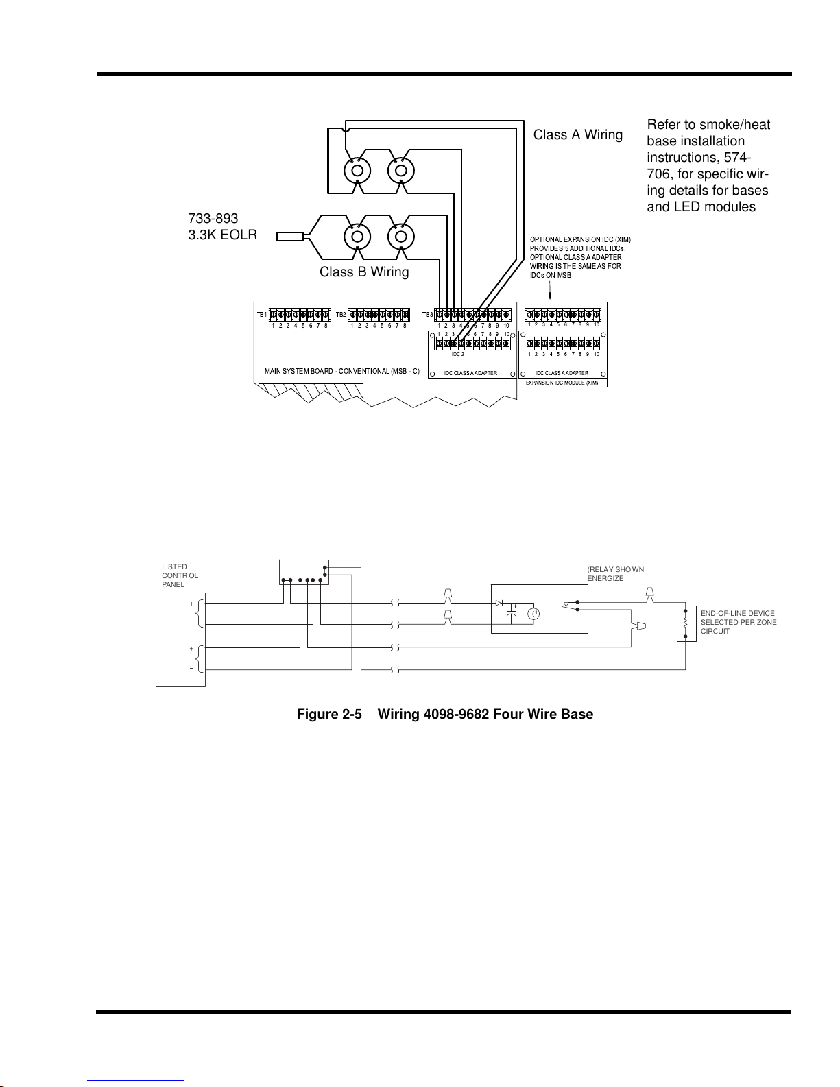
IDC Wiring
• All wiring must be 18 AWG min. to 12 AWG max.
• Conductors must test free of all grounds and stray voltages before connection to appliances and panel.
• All wiring is supervised and power-limited. IDCs
should be segregated from AC supply wiring. If wired
power-limited, segregate IDC wiring from non-power
limited wiring.
• Leave a 3.3K, 1/2 W resistor (supplied) across all
unused IDC terminals.
• Terminate Class B circuits with listed 3.3K, 1W end-ofline resistor, part number 733-893. For Canadian applications, mount end-of-line resistor to TEPG-US Model
431537 EOL plate in accordance with ULC-S527.
• Class A Circuits. Wire as follows:
- Wire from B+/B- from of TB3 to each initiating
device. Wire in a daisy-chain style, in and out from
each device to the next device.
- Do not “T-Tap” wiring.
- Wire from last device back to the A+/A- terminals
on the Class A adapter for that circuit. EOLR is
built onto Class A board.
• For Class A, set CLA Adapter 1 (IDCs 1-5) or CLA
Adapter 2 (IDCs 1-10) System Option to ON. If using
expansion IDC module, set EXP IDC system option to
ON. See Chapter 6.
• Class B Circuits. Wire the circuit to the B+ / B- terminals. The circuit must be wired with IN/OUT wiring
from detector to detector and terminate with 733-893
EOLR.
• Maximum allowed wiring resistance is 50 ohms per circuit. Suggested wire is 18 AWG, allowing up to 3500’
distance from panel to EOLR (Class B) or Class A
Board (Class A). For Simplex Model 4098-9683 relay
base, limit is one device per circuit. For all other detectors and bases, up to 30 devices per circuit are allowed.
• Maximum detector standby current is 3 mA per IDC.
Maximum detector alarm current is 60 mA per IDC.
16-32 VDC, 1/2 V peak-to-peak maximum ripple. Maximum circuit capcitance is 100 uf per IDC.
• Compatible detectors:
- 4098-9601, photoelectric smoke (2.8%) detector
- 4098-9602, combination photo/heat detector
- 4098-9605, photoelectric smoke (special
sensitivity) detector
- 4098-9612, 135° F, Fixed temp heat detector
- 4098-9613, 135° F, Fixed temp/rate of rise heat
- 4098-9614, 200° F Fixed temp heat detector
- 4098-9615, 200° F Fixed temp/rate of rise heat
The compatibility identifier is the model number associated with the board or module.
• Compatiblebases:
- 4098-9788, two-wire base (max. 30 per loop).
- 4098-9683, two-wire base with auxiliary relay
(limit of one per IDC).
- 4098-9684, two-wire base with LED for use with
heat detectors 4098-9612
- through 9615 (max. 30 per loop).
- 4098-9682, 4-wire base with aux. alarm relay (max.
30 per loop). See “Wiring 4098-9682 Four-Wire
Base” below.
Technical Manuals Online! - http://www.tech-man.com
2-3
Page 22
Chapter 2. Installation and System Checkout
TB1
1 2 3 4 5 6 7 8
TB2
1 2 3 4 5 6 7 8
TB3
1 2 3 4 5 6 7 8 9 10
1 2 3 4 5 6 7
IDC 2
IDC CLASS A ADAPTER IDC CLASS A ADAPTER
EXPANSION IDC MODULE (XIM)
8 9 10
1 2 3 4 5 6 7 8 9 10
1 2 3 4 5 6 7 8 9 10
MAIN SYSTEM BOARD - CONVENTIONAL (MSB - C)
OPTIONAL EXPANSION IDC (XIM)
PROVIDES 5 ADDITIONAL IDCs.
OPTIONAL CLASS A ADAPTER
WIRING IS THE SAME AS FOR
IDCs ON MSB
733-893
3.3K EOLR
Class A Wiring
Class B Wiring
Refer to smoke/heat
base installation
instructions, 574706, for specific wiring details for bases
and LED modules
LISTED
CONTROL
PANEL
END-OF-LINE DEVICE
SELECTED PER ZONE
CIRCUIT
(RELAY SHOWN
ENERGIZED)
YELLOW
YELLOW
TYPICAL 4-WIRE ZONE
24VDC DEVICES
TYPICAL 4-WIRE
DETECTOR
24VDC
RED
BLACK
E.O.L. RELAY
24 VDC
Power
IDC
R
2098-9735
Figure 2-4 IDC Wiring
Wiring 4098-9682 Four-Wire Base
When the 4098-9682 base is used, the auxiliary 24V power
must be routed through 2098-9735 end-of-line relay, as
shown in Figure 2-5.
Figure 2-5 Wiring 4098-9682 Four Wire Base
Technical Manuals Online! - http://www.tech-man.com
2-4
Page 23

Chapter 2. Installation and System Checkout
Main
System
Board
EPS
NACs
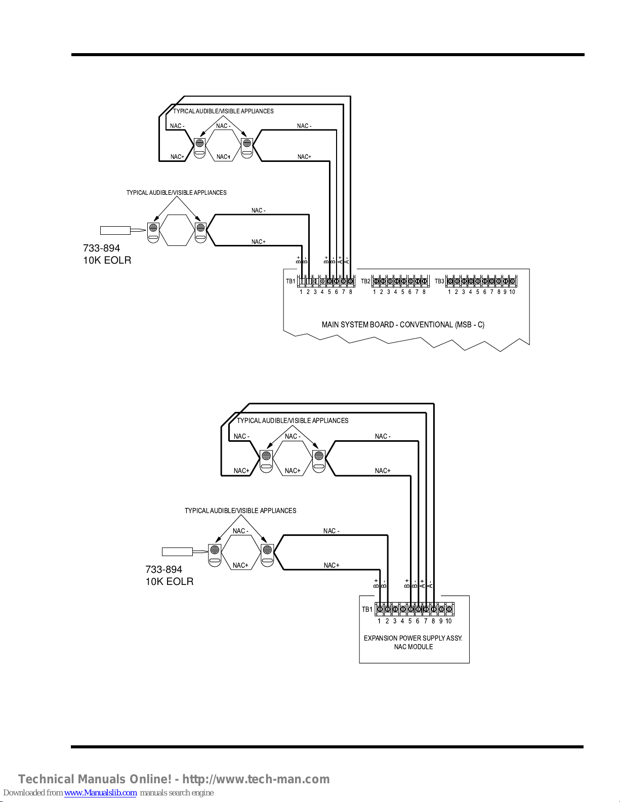
NAC Wiring
General Wiring Notes -- Apply to NACs on Main
System Board (MSB) and Expansion Power Supply
Refer to Figure 2-6 and Figure 2-7.
• All wiring must be 18 AWG (min.) to 12 AWG (max.).
• Conductors must test free of all grounds and stray voltages before connection to appliances and panel.
• All wiring is supervised and power limited.
• Terminate Class B (Style Y) NACs as shown using 733-
894. For Canadian applications, mount end-of-line
resistor to TEPG-US Model 431537 EOL plate in accordance with ULC-S527.
• Wire Class A (Style Z) NACs from B+/B- to each appliance as shown. No EOL device is required. Connect
wires from +/- terminals of last appliance to the A+/Aterminals as shown.
• System is shipped with 10K, 1/2 W resistors connected
across NAC B+/B- of each circuit. Remove this resistor
from any circuits in use. Leave resistor installed if circuits are unused.
• Voltage rating: Refer to “NAC Ratings” on Page 2-7 for
specific voltage specifications. Maximum ripple: 1/2V
peak-to-peak.
• Current rating: 2A maximum for either circuit. 3A total
between both circuits and Aux. 24 V load.
• Terminal designations (+/-) are for the alarm state.
• When using two-wire audible/visible appliances, maximum wiring capacitance must be considered. For
TrueAlert Non-Addressable notification appliances,
.22uF maximum is allowed.
• If wiring is routed outside the building, use of a listed
secondary protector is required. Use Simplex 20819028 or 2081-9044. A protector must be installed at
each building exit/entrance. Each 2081-9028 adds .2
ohms wiring resistance. 2081-9044 adds 6 ohms wiring
resistance. Use of 2081-9044 will greatly reduce wiring
distance.
• Wiring chart gives max. distance for 1/4 -2A loads. For
Class B circuits wiring distance is from panel terminals
to last appliance. For Class A circuits, wiring distance is
from panel terminals to last appliance and back to panel
terminals. Use of 2081-9044 reduces wiring distance.
Table 2-1 Wiring Distances
Maximum Wiring Distance in Feet
Alarm
Current
(Amps)
.25 840 1335 2126 3382 12
.50 420 667 1063 1691 6
.75 280 445 709 1127 4
1.0 210 334 532 845 3
1.25 168 267 425 676 2.4
1.50 140 222 354 564 2
1.75 120 191 304 483 1.71
2.0 105 167 266 423 1.5
18
AWG
16
AWG
14
AWG
12
AWG
Line
Resistance
(Ohms)
Location of Expansion Power Supply NACs (If
Used)
The Expansion Power Supply (EPS) is located to the bottom
right of the main system board (MSB), as shown below. Wiring guidelines for these NACs are identical to the guidelines
for the MSB NACs.
Technical Manuals Online! - http://www.tech-man.com
2-5
Page 24
Chapter 2. Installation and System Checkout
TB1
NAC -
TYPICAL AUDIBLE/VISIBLE APPLIANCES
NAC+
NAC -
NAC+
TYPICAL AUDIBLE/VISIBLE APPLIANCES
NAC -
NAC+
NAC -
NAC+
TB2
1 2 3 4 5 6 7 8 1 2 3 4 5 6 7 8 1 2 3 4 5 6 7 8 9 10
TB3
MAIN SYSTEM BOARD - CONVENTIONAL (MSB - C)
B +
B -
B +
B -
A +
A -
733-894
10K EOLR
NAC -
TYPICAL AUDIBLE/VISIBLE APPLIANCES
NAC+
NAC -
NAC+
NAC -
NAC+
TYPICAL AUDIBLE/VISIBLE APPLIANCES
NAC -
NAC+
TB1
EXPANSION POWER SUPPLY ASSY.
NAC MODULE
1 2 3 4 5 6 7 8 9 10
NAC -
NAC+
B +
B -
B +
B -
A +
A -
733-894
10K EOLR
Figure 2-6 Main System Board NACs
Technical Manuals Online! - http://www.tech-man.com
Figure 2-7 Expansion Power Supply NACs
2-6
Page 25

Chapter 2. Installation and System Checkout
NAC ratings
The panel is rated Special Application for 2A maximum per
NAC with Simplex 4901 and 4906 TrueAlert & TrueAlert
Multi-Candela Notification Appliances.
For all other UL Listed Notification Appliances, NACs are
rated regulated 24 VDC at 1.5 A maximum each. Maximum
allowed strobe load on either the main or expansion power
Table 2-2 NAC Ratings
15Cd 30Cd 75Cd 110Cd
4906-
9101 0.060 33 0.094 21 0.186 10 0.252 7
9102 0.075 26 0.125 16 0.233 8 0.316 6
9103 0.060 33 0.094 21 0.186 10 0.252 7
9104 0.075 26 0.125 16 0.233 8 0.316 6
9127 0.075 26 0.116 17 0.221 9 0.285 7
9128 0.086 23 0.132 15 0.250 8 0.320 6
9129 0.075 26 0.116 17 0.221 9 0.285 7
9130 0.086 23 0.132 15 0.250 8 0.320 6
Rated
Current
Max. # per
NAC
Rated
Current
Max. #
per NAC
supply is 1.35 A. The balance of the 3 A capacity can be
auxiliary loads or audible notification appliances.
Synchronization of strobes across all NACs in a system is
UL Listed for the Simplex models noted in the table below.
See the table below for maximum number allowed of each
appliance per NAC.
Rated
Current
Max. # per
NAC
Rated
Current
Max. # per
NAC
9151 0.060 33 0.094 21 0.186 10 0.252 7
9154 0.075 26 0.125 16 0.233 8 0.316 6
9153 0.060 33 0.094 21 0.186 10 0.252 7
All other regulated 24 VDC synchronized notification
appliances require the use of their associated, listed external
synchronization module. Notification Circuit rating is 1.5 A
maximum, 1.35 A maximum strobe load per power supply.
Use the UL-rated operating current to determine maximum
number of appliances allowed per NAC.
Technical Manuals Online! - http://www.tech-man.com
2-7
Page 26

Chapter 2. Installation and System Checkout
Auxiliary Relay Wiring
• All wiring must be 18 AWG (minimum) to 12 AWG
(maximum). Conductors must test free of all grounds
and stray voltages before connection to appliances,
devices, and panel.
• Contact rating: 30VDC @ 2A, 0.35 power factor
• If using expansion relay module, set EXP RELAY system option to ON.
• Each relay is selected for normally closed or normally
open operation. Shunt jumper setting (see figure) selects
desired contact.
• Relay 1 is programmable. Its default operation is Common Alarm - On Until Reset. Jumper is P1.
• Relay 2 is a normally energized, common trouble relay.
The jumper settings noted in the figure account for the
relay being normally energized. Jumper is P2.
• When the panel is completely powered off, the trouble
relay will be in the “Off Normal” state.
• All wiring is unsupervised.
Figure 2-8 Relays on Main System Board
Technical Manuals Online! - http://www.tech-man.com
2-8
Page 27

Chapter 2. Installation and System Checkout
DANGER
HIGH VOLTAGE
IN THIS AREA
DACT TELEPHONE
CONNECTIONS
LINE 2 TELCO SERVICE IN
LINE 1 TELCO SERVICE IN
WIRE TO MODULAR JACK
TO USE LINE 1 FOR
OTHER TELCO EQUIP.
WIRE TO MODULAR JACK
TO USE LINE 1 FOR
OTHER TELCO EQUIP.
1 2 3 4 5 6 7 8 1 2 3 4 5 6 7 8 1 2 3 4 5 6 7 8 9 10
TB1 TB2 TB3
MAIN SYSTEM BOARD - CONVENTIONAL (MSB - C)
TB5
1 2 3 4 5 6 7 8
R
I
N
G
R
I
N
G
R
I
N
G
R
I
N
G
T
I
P
T
I
P
T
I
P
T
I
P
DACT
The DACT connection is made from the Main System Board
to the public telephone system via terminals TB5-1/TB5-2
and TB5-5/TB5-6. Wiring information is shown in
Figure 2-9.
• The DACT requires two telephone line connections to
meet NFPA72 requirements. Wire from TB5-3/TB5-4
and TB5-7/TB5-8 to an RJ-11 or other Telcom wiring
block for connection to other telephone equipment. The
DACT will seize control of the telephone line (if necessary) to transmit emergency messages. When wired as
shown, the DACT will properly control access to lines
in an emergency.
• Wire from Telcom equipment to TB5 using 18 AWG to
24 AWG.
• All DACT wiring is supervised.
• Digital Alarm Communicator Receiver (DACR) compatibility is shown in Table 2-3.
• If wiring is routed outside the building, use of a listed
secondary protector is required. Use Simplex 20819028 or 2081-9044. A protector must be installed at
each building exit/entrance. Each 2081-9028 adds .2
ohms wiring resistance. 2081-9044 adds 6 ohms wiring
resistance. Use of 2081-9044 will greatly reduce wiring
distance.
Figure 2-9 DACT Wiring
Technical Manuals Online! - http://www.tech-man.com
2-9
Page 28

Chapter 2. Installation and System Checkout
Table 2-3 Compatible DACRs
Digital Alarm Communicator Receiver (DACR)
Communication
Format
Contact ID
(Preferred)
3/1 Standard
1800/2300 Hz
(10 and 20PPS)
3/1 Standard
1900/1400 Hz
(10 and 20PPS)
4/2 Standard
1800/2300 Hz
(10 and 20PPS)
4/2 Standard
1900/1400 Hz
(10 and 20PPS)
Radionics
BFSK
1800/2300 Hz
Simplex
Central
Station
Services
2, 3
FBII
CP220FB
Osborne/
Hoffman
QuickAlert
II
ADEMCO
1, 3
685
SUR-
GARD
MLR2-DG
Radionics
D6600
Silent
Knight
9000
Silent
Knight
9500
With 9032
Line Card
With 9032
Line Card
With 9032
Line Card
With 9032
Line Card
With 9032
Line Card
SUR-
GARD
MLR
2000
TBD
TBD
TBD
TBD
TBD
Radionics
BFSK
1900/1400 Hz
SIA
Notes:
1. With 685-8 Line Card
2. With Rec-11 Line Card
3. These receivers are also Factory Mutual (FM) approved.
With 9032
Line Card
TBD
TBD
Technical Manuals Online! - http://www.tech-man.com
2-10
Page 29

Chapter 2. Installation and System Checkout
1 2 3 4 5 6 7 8
1 2 3 4 5 6 7 8
TB2
TB1
N2
Comms
-
+
0V Shield
(If Used)
MSB
MSB
RAMRAM
RAM
RAM
RAM
RAM
RAM
T-Tap Style Wiring
Bus Style Wiring
A A
A
RAM = Remote Annunciator Module
MSB = Main System Board
Remote Annunciator Wiring
• All wiring must be 18 AWG (min.) to 12 AWG (max.),
twisted pair or shielded twisted pair.
• Conductors must test free of all grounds and stray voltages before connection to appliances, devices, or panel.
• All wiring is supervised and power-limited.
• Refer to instructions packed with remote annunciator
modules for connection details to each module.
• Remote annunciators require power and communications wiring.
• For “bus-style” wiring (see figure), maximum wiring
limit is 4, 000 feet.
- Maximum wiring capacitance is 0.58µF total,
wire-to-wire plus wire-to-shield.
- Attach 733-974 (100 ohm, 1/2W) resistor as shown
for line matching. See Note A in figure below. Wire
remote devices “daisy-chain” style, using in/out
terminals on each device.
• For “T-Tap” style wiring, total cable limit is 10,000 feet,
2,500 feet to the furthest device.
- Maximum wiring capacitance is .58uF total, wire-
to-wire plus wire-to-shield.
- Attach 733-974 (100 ohm, 1/2W) resistor (see Note
A in figure) for line matching.
• Shielded wire is not required for most installations. If
communications wiring is not in conduit with strobes or
voice speaker circuits, shielded wiring is not required.
Use shielded wiring if remote annunciator wiring shares
a conduit with these signals. Terminate shield to 0V
(Aux 24V Neg.) or to chassis.
• If wiring is routed outside the building, use of a listed
secondary protector is required. Use Simplex 20819028 or 2081-9044. A protector must be installed at
each building exit/entrance. Each 2081-9028 adds .2
ohms wiring resistance. 2081-9044 adds 6 ohms wiring
resistance. Use of 2081-9044 will greatly reduce wiring
distance.
• Wiring must pass through a ferrite bead. Wrap the wiring twice through the ferrite bead, as shown in
Figure 2-12.
Figure 2-10 Annunciator Wiring Connections
Figure 2-11 Bus Style and T-Tap Wiring
Technical Manuals Online! - http://www.tech-man.com
Figure 2-12 Ferrite Bead
2-11
Page 30

Chapter 2. Installation and System Checkout
EMPLOY A 14.5 OHM TRIP COIL.
P5
LE
RP
LE
RP
P4
10 9
8 7
6 5
4 3
2 1
P3
LE
RP
LE
RP
P2
10 9
8 7
6 5
4 3
2 1
P6
1
2
3
4
City Connect Module Wiring
• City connect module mounts to the main system as
shown. Refer to City Module Installation Instructions
for details.
• City module consists of two circuits that are jumperconfigured. Circuits may be configured for reversepolarity or local energy operation. See jumper setting
table for details. Modules must also be added to the system configuration. See “System Options” later in this
manual.
• All wiring to be per NPFP-72, NEC, and local codes.
Minimum 20 AWG for reverse polarity; minimum 18
AWG for local energy circuits.
• Conductors must test free of all grounds.
• Wiring is supervised for opens and grounds, but not
power-limited.
• For specific information about reverse polarity and local
energy circuits, see Figure 2-13.
• If wiring is routed outside the building, use of a listed
secondary protector is required. Use Simplex 20819028 or 2081-9044. A protector must be installed at
each building exit/entrance. Each 2081-9028 adds .2
ohms wiring resistance. 2081-9044 adds 6 ohms wiring
resistance. Use of 2081-9044 will greatly reduce wiring
distance.
• Circuits are shipped with 3.3K, 1/2W resistor installed.
Remove resistor before wiring circuit. Leave installed
on unused circuits.
Figure 2-13 City Connect Module Wiring
Technical Manuals Online! - http://www.tech-man.com
2-12
Page 31

Chapter 2. Installation and System Checkout
Auxiliary 24 V Wiring
• All wiring must be 18 AWG (minimum) to 12 AWG
(maximum).
• Conductors must test free of all grounds and stray voltages before connection to appliances, devices, and
panel.
• All wiring is supervised and power-limited.
• Voltage rating (24 VDC special application): 1 V p-p
ripple (maximum)
- 0.5 A maximum available aux 24 V from EPS
- Additional 0.5 A maximum available from Main
System Board (MSB) AUX 24 V
- 3 A total available from MSB NACs and MSB
AUX 24 V.
- 3 A total available from EPS NACs and EPS AUX
24 V.
• Compatible with Simplex 4098 Series Peripherals; 2098
Series Relay Modules; all Simplex 4090 Series IDNet
Peripherals; and 4610-9111 / 4606-9101 Annunciators.
• If wiring is routed outside the building, use of a listed
secondary protector is required. Use Simplex Model
2081-9028 or 2081-9044. A protector must be installed
at each building exit/entrance. Each 2081-9044 adds 6
ohms wiring resistance, and is rated for 200mA. Each
2081-9028 adds .2 ohms wiring resistance, and is rated
for more than 1/2A Aux. 24V capacity.
• Compatible devices must operate from a range of 19.5
to 28 VDC or greater, and have a total current draw of 1/
2 A or less.
Figure 2-14 Aux 24V Wiring
Technical Manuals Online! - http://www.tech-man.com
2-13
Page 32

Chapter 2. Installation and System Checkout
TB1
DANGER
HIGH VOLTAGE
IN THIS AREA
DACT TELEPHONE
CONNECTIONS
EXPANSION POWER SUPPLY ASSY.
NAC MODULE
THE POWER SUPPLY MODULE, PART OF THE EPS
ASSEMBLY, IS MOUNTED BENEATH THE NAC MODULE
PORTION OF THE EPS ASSEMBLY.
734 - 179
WIRE AC LINE AND NEUTRAL AS SHOWN.
HOT TO LEFT TERMINAL, NEUTRAL TO RIGHT TERMINAL.
WHITE
LINE
NEUTRAL
BLACK
WHITE / BLACK HARNESS 734 - 179
FROM EPS (LOWER MODULES)
TO MAIN SYSTEM BOARD.
EPS
POWER SUPPLY MODULE
TB5
1 2 3 4 5 6 7 8
TB2
1 2 3 4 5 6 7 8
TB3
1 2 3 4 5 6 7 8 9 10
TB1
B+ B- B+B- A+ A-
1 2 3 4 5 6 7 8 9 10
1 2 3 4 5 6 7 8
MAIN SYSTEM BOARD - CONVENTIONAL (MSB - C)
Connecting to AC Power
• Before handling AC feed, use a voltmeter to verify the
feed is not live. Make sure the circuit is de-energized
and tagged to prevent injury.
• AC feed must be routed in the wiring area below the
main system board, in the area designated “not power
limited.”
• AC power must be wired from a dedicated circuit
breaker or fuse, rated 20 A, per NFPA-72, NEC, and
local codes.
• AC supply wiring must be 14 AWG minimum to 12
AWG maximum.
• Connect a 12 AWG copper ground wire from safety
ground in the electrical distribution panel to the panel
safety ground stud.
• Input voltage range:
- 120 VAC, 60 Hz
- 240 VAC, 50Hz
- No configuration settings required to select
• The Expansion Power Supply (EPS) is an option, and
requires AC power when used. Connect the Black/
White AC harness from the EPS to the TB4 AC input
terminals on the main system board. Wire Black to the
left terminal of TB4. Wire White to the right terminal of
TB4.
• AC wiring is supervised. Safety ground wire is not
supervised.
• Supply Power Requirements
- 120 VAC 60 Hz, 2A maximum
- 240 VAC 50 Hz, 1.5A maximum
1. Remove insulating cover marked with the high voltage
warning.
2. Connect AC feed wires to terminal block located at bottom left of board. Terminals are labeled LINE (120V)
and NEUTRAL. Wire the AC feed through the ferrite
bead (provided). Refer to Figure 2-18.
3. Before applying AC power to the system, connect the
batteries per the instructions on the following page, and
replace the protective cover removed in step 1.
4. Connect Safety Ground from electrical service to
mounting stud (see Figure 2-18) marked with Earth
symbol. Use a terminal lug that is suitable for the
ground wire and nut used.
5. Replace protective cover.
Technical Manuals Online! - http://www.tech-man.com
Figure 2-15 AC Wiring
2-14
Page 33

Chapter 2. Installation and System Checkout
TB1
DANGER
HIGH VOLTAGE
IN THIS AREA
DACT TELEPHONE
CONNECTIONS
EXPANSION POWER SUPPLY ASSY.
NAC MODULE
THE POWER SUPPLY MODULE, PART OF THE EPS
ASSEMBLY, IS MOUNTED BENEATH THE NAC MODULE
PORTION OF THE EPS ASSEMBLY.
734 - 180
ATTACH TO BATTERY CONNECTOR
RIGHT - JUSTIFIED, BLACK WIRE TO THE RIGHT
CONNECT TO
BATTERY TERMINALS
(FUSED ON PCB)
BLACK
RED
HARNESS 734 - 180
FROM EPS (LOWER MODULES)
TO MAIN SYSTEM BOARD
BATTERY CONNECTOR
EPS
POWER SUPPLY MODULE
TB5
1 2 3 4 5 6 7 8
TB2
1 2 3 4 5 6 7 8
TB2
1 2 3 4 5 6 7 8 9 10
TB1
3B+
3B-
3A+
3A-
4B+
4B-
4A-
4A-
24V
0V
1 2 3 4 5 6 7 8 9 10
1 2 3 4 5 6 7 8
MAIN SYSTEM BOARD - CONVENTIONAL (MSB - C)
R
E
D
R
E
D
B
L
K
B
L
K
Wiring Battery Power
• The main battery harness connects the main system
board to the battery set in the same cabinet.
• The system requires 24V battery backup. Use two 12V
batteries, connected in series. The main battery harness
connects to the .250” fast-on battery terminals, as follows:
1. Connect black wire to the negative battery terminal
of Battery 1
2. Connect white wire from the positive battery termi-
nal of Battery 1 to the negative battery terminal of
Battery 2.
3. Connect the red wire to the positive battery termi-
nal of Battery 2.
• Connect the main battery harness to the four-position
header, located approximately in the center of the bot-
tom edge on the main system board. Insert the connector left-justified, with the red wire to the left.
• The EPS connects to the battery header next to the battery harness described in the previous bullet. Install the
EPS red/black harness right-justified to the battery
header, with the black wire to the right.
• Battery circuit is supervised, but not power-limited.
• For depleted battery cutout operation, remove jumper
per installation instructions. Separate jumper removal
required for main system board and EPS. System programming option “Depleted Battery Cutout” must also
be selected. ULC-S527 depleted battery operation
requires jumper removal.
• For 18 Ah or larger batteries, the 4009-9801 external
battery cabinet must be used. Mount the battery box
within 20 feet of the control panel, in accordance with
the mounting instruction label in the box. All interconnecting wiring must be enclosed in conduit.
Figure 2-16 Battery Connections
Technical Manuals Online! - http://www.tech-man.com
2-15
Page 34

Chapter 2. Installation and System Checkout
LINE NEUTRAL
BATT EPS
+ - + -
Remove this
Jumper
Depleted Battery Cutout
For depleted battery cutout, remove the jumper shown in
Figure 2-17 from the main system board. If you are using an
Expansion Power Supply (EPS), you must also remove
Jumper R76 from the EPS. (When programming the panel,
make sure to enable the Depleted Battery Cutout system
option.)
Figure 2-17 Location of Depleted Battery Jumper
Safety Ground/Ferrite Bead
System Powerup and Checkout
Use the following procedure to apply AC and battery power
to the 4006.
On power up, the panel performs the following:
• Displays revision of boot-loader software
• CPU self test
• Link Scan - checks for a programming unit connection
• Memory Test - Verifying system and job-specific software
• Startup - 4006 Exec startup
If the panel successfully completes its start up self-test, it
will indicate a warm or cold start trouble, which clears when
acknowledged. If there are no other troubles in the system,
the following is displayed:
SYSTEM NORMAL
12:00 am 21-FEB-03
If other troubles exist in the system, the following is displayed:
FIRE | SUPV | TRBL
00 | 00 | 02
Proper operation and protection against transient energy per
UL864 and ULC-S527 requires connection of safety ground
wire to cabinet chassis as shown in Figure 2-18.
In addition, a ferrite bead must be attached to the incoming
AC power line as shown in the figure. Wrap the LINE and
Neutral legs of the power line twice through the ferrite bead.
Figure 2-18 Safety Ground and Ferrite Bead
Pressing the <TROUBLE ACK> key allows the operator to
acknowledge the troubles (silencing the panel sounder) and
scroll through the troubles on the active Trouble List.
If the 4006 self-test fails, the panel displays an error code
and waits 30 seconds before attempting a restart.
Acceptance Testing
When you are finished with the original installation, programming and all modifications, conduct a complete operational test on the entire installation to verify compliance with
applicable NFPA standards and Local Codes. Testing should
be conducted in the presence of a representative of the
Authority Having Jurisdiction (AHJ), and the customer's
representative. Follow procedures outlined in Chapter 10
“Inspection, Testing, and Maintenance” of NFPA standard
72-2002 and as dictated by local codes.
Testing Circuit Supervision
Use the following procedures to confirm that IDCs and
NACs are supervising for opens, shorts and grounds. The
right column in this table shows the LEDs that illuminate
when an open, short, or ground occurs on a specific circuit.
Technical Manuals Online! - http://www.tech-man.com
2-16
Page 35

Table 2-4 Testing Circuit Supervision
Condition Corresponding LEDs
To create an open:
• Class B Circuit. Remove the
end-of-line resistor from
either the IDC or NAC.
• Class A Circuit. Disconnect
the return wiring from the
main system board (NAC
only), or from the IDC Class A
module.
To create a short:
Apply a zero ohm jumper across
the IDC or NAC circuit.
To create an Earth ground:
Place a 10K or smaller value resistor from supervised wiring to Earth
ground.
Illuminates the System Trouble
LED.
Illuminates the System Trouble
LED.
Illuminates the System Trouble
LED.
If you have programmed a front
panel or annunciator LED to detect
Earth ground conditions, the programmed LED also illuminates.
Refer to “Common Panel LED
Applications” in Chapter 5 of this
manual for information on programming an Earth Fault LED.
Chapter 2. Installation and System Checkout
Test mode is activated by placing the magnet at the location
indicated by the "I" mark, which is embossed on the detector
housing. The visible LED flashes to indicate the detector's
condition.
• NORMAL - When in test mode, the detector latches
into alarm if the unit is within calibration range. The
visible LED stays on, with no blink codes transmitted.
• MORE SENSITIVE - When in test mode, if the detector
is too sensitive, (more sensitive than the maximum calibration), the visible LED quickly flashes, at a twice per
second rate. Following the sixth flash, the detector
latches into alarm and the visible LED stays ON.
• LESS SENSITIVE - When in test mode, if the detector
is less sensitive than the minimum calibration, the visible LED slowly flashes, at a rate of one flash every two
seconds. Following the fourth flash, the detector latches
into alarm and the visible LED stays ON.
Table 2-5 Test Modes
State Normal Test
Mode
Replacing Lithium Battery
The panel uses a lithium battery to maintain non-volatile
memory on the panel. In the event of a total power-down
(AC power and lead-acid battery), the lithium battery allows
the panel to maintain all historical logs, time/date information, list of disabled points, and the alarm verification tallies.
Important Note: The lithium battery must be replaced only
by a qualified service technician.
Periodic Testing and Maintenance
The minimum requirements for periodic testing of the fire
alarm system are outlined in chapter 10 of NFPA-72, 2002
edition. Local codes may require additional testing and
maintenance. All system components must be tested in
accordance with governing codes. Specific details on select
system components are provided below.
Smoke Detector Tests
The detectors include magnetically operated functional tests.
The magnet tests indicate if the detector is within sensitivity
settings. The detector will also indicate whether or not it
needs cleaning due to buildup of dirt or dust. This indication
is via LED blink codes. The table shown below shows the
blink codes associated with the detectors during magnetic
test. Refer to the detector installation documents for additional details.
LED
Normal X X
More Sensitive
Less Sensitive
Not Functioning
flashes
every 4
seconds
X X X
X X X
X
LED fastflashes
six times
LED
slowflashes
four times
Latches
in alarm
LED
stays ON
Battery Tests
The batteries used with the 4006 FACP are sealed lead-acid
type. The battery charger is temperature compensated per
battery manufacturer recommendations. There is no charger
voltage adjustment. Batteries should be tested by discharging them with a suitable tester and verifying that battery
voltage is at least 21V when fully discharged. Battery discharge tests should be performed annually, and batteries
should be replaced no longer than 4 years from date of
installation. Batteries should be installed within six months
of the date of manufacture. At normal room temperature,
battery voltage should be 27-27.6V when the battery set is
fully charged. At higher temperatures, the voltage will be
lower. At lower temperatures, the voltage will be higher. The
battery charger has a negative temperature coefficient. At
higher temperatures, the chemical process in the battery is
accelerated. This means that the ideal charger voltage is
lower. Likewise, at lower temperatures, a higher output volt-
Technical Manuals Online! - http://www.tech-man.com
2-17
Page 36

Chapter 2. Installation and System Checkout
age is required for full charge. Control of battery charge
voltage relative to ambient temperature prolongs battery life.
The chart below shows the proper range of battery voltage
across the specified operating range of the equipment. The
chart is for 12-cell battery sets, with nominal 24V rating.
Table 2-6 Voltage Versus Temperature
Temp
(C)
10 50 2.274 2.337 27.29 28.04
15 59 2.264 2.322 27.17 27.86
22.2 72 2.250 2.300 27.00 27.60
25 77 2.244 2.292 26.93 27.50
30 86 2.234 2.277 26.81 27.32
35 95 2.224 2.262 26.69 27.14
40 104 2.214 2.247 26.57 26.96
45 113 2.204 2.232 26.45 26.78
49 120.2 2.196 2.220 26.36 26.64
Temp
(F)
0 32 2.294 2.367 27.53 28.40
5 41 2.284 2.352 27.41 28.22
V/cell
(min.)
V/cell
(max)
Min.
Battery
Voltage
Max.
Battery
Voltage
Technical Manuals Online! - http://www.tech-man.com
2-18
Page 37

Chapter 3. Programming IDCs, NACs, and
AUX Relays
NOTICE TO INSTALLERS, AUTHORITIES HAVING JURISDICTION, AND OTHER INVOLVED PARTIES
This product incorporates field-programmable software. In order for the product to comply with the requirements in the Standard for Control Units and Accessories for Fire Alarm Systems, UL 864, certain programming features or options must be
limited to specific values or not used at all as indicated below.
Program Feature or Option Permitted in UL 864? (Y/N) Possible Settings Settings Permitted in UL 864
FIRE, WATER, HEAT,
DUCT, PULL, SMOKE, SO,
IDC Function Type Y
NAC Function Type Y
Relay Function Type Y
WSO, SUPV, UTIL, TROUBLE, VSMOKE, STYLEC,
LATSUPV
QALERT, SSIG, RSIG,
SUPV, TRBL, UTILITY
SRELAY, RRELAY, SUPV,
TRBL, UTILITY, PRIMARY,
ALTERN, DRESET,
DHOLDER, TEMPORAL,
STEADY, SYNCH, 20 BPM,
120 BPM
This chapter describes setting the characteristics of each initiating
device, notification appliance, and the programmable AUX relay to the
specific values required for the job. Refer to Chapter 4 for information
on programming the DACT; refer to Chapter 5 for information on programming annunciator LEDs.
You can set the following attributes for each of the panel’s IDCs, NACs,
and AUX Relays:
• Function Type. Determines the operation of the point. For a NAC
or relay, for example, you can set whether the device turns off on
silence or reset, etc.
• Label. Up to 20 characters can be used to create a custom label for
the point. A word library, containing common words associated
with fire alarm points, and an alphanumeric keypad allow labels to
be quickly and accurately created.
• Alarm Group. Applies to NACs, Relays, and Initiating Device
Circuit points. Allows you to define selective signalling groups.
Each NAC or Relay point can be associated with up to three alarm
groups, allowing you to specify which initiating devices are
allowed to activate the device.
FIRE, WATER, HEAT,
DUCT, PULL, SMOKE, SO,
WSO, SUPV, TROUBLE,
VSMOKE, STYLEC, LATSUPV
QALERT, SSIG, RSIG,
SUPV, TRBL
SRELAY, RRELAY, SUPV,
TRBL, PRIMARY, ALTERN,
DRESET, DHOLDER, TEMPORAL, STEADY, SYNCH,
20 BPM, 120 BPM
In This Chapter
Default General Alarm Programming . . . . . . . 3-2
Accessing Menus . . . . . . . . . . . . . . . . . . . . . . 3-2
Editing IDCs . . . . . . . . . . . . . . . . . . . . . . . . . . 3-2
Programming NACs . . . . . . . . . . . . . . . . . . . . 3-5
Programming AUX Relays . . . . . . . . . . . . . . . 3-8
Saving Changes. . . . . . . . . . . . . . . . . . . . . . . 3-9
Technical Manuals Online! - http://www.tech-man.com
3-1
Page 38

Chapter 3. Programming IDCs, NACs, and AUX Relays
Keep the following in mind if you are adding or deleting an
expansion IDC module.
• Adding Expansion IDCs (only if 4006-9802 Expan-
sion IDC Module is installed). To add an expansion IDC
module to the job, set the “Exp IDC” system option,
described in Chapter 6 of this manual, to ON.
• Deleting Expansion IDCs (only if 4006-9802 Expan-
sion IDC Module was previously installed and has been
removed). To delete an expansion IDC module from the
job, change the setting of the “Exp IDC” system option
from ON to OFF. The “Exp IDC” option is described in
Chapter 6 of this manual.
If an Expansion Power Supply Module is installed in the
system, you must first set the Expansion Power Supply system option to ON before programming NACs. Refer to
Chapter 6 - System Options for information on doing this.
All operations described in this chapter require you to first
login at Access Level 4. See Chapter 1 for information on
doing this.
Note: The <Exit/Clear> key is used to back out of menus or
displays and return to the top-level menu structure. Where
possible, the <Exit/Clear> key backs out one level at a time.
There are cases, however, that the Exit/Clear key will return
the operator directly to the top-level menu.
2. Press <ENTER>. The Programming menu appears.
[Points] is the default selection, which allows you to
make changes to a specific point’s programming.
<ENTER>=Accept
Prg:[Points]
3. Press <ENTER>. A prompt appears, allowing you to
select the type of point to manually edit. By default,
[IDC] is the first choice.
<ENTER>=Accept
Prg:[IDC]
4. Use the <NEXT> and <PREV> keys to scroll to the
appropriate choice and then press <ENTER>.
• IDC
• NAC
• RELAY (Use for on-board and expansion relays).
Select the operation you want to perform and see the appropriate section in this chapter. (The other options that appear
when you perform Step 4 -- LED, Input, User SW LED -apply to annunciators. Programming annunciator points is
described in Chapter 5 of this manual.)
Editing IDCs
Default General Alarm Programming
The panel ships with the following default programming
installed on the panel.
• All IDCs are configured as general fire alarm monitor
zones.
• NAC1 and NAC2 are configured for on-til-silence operation (temporal coding).
Accessing Menus
Use the following steps to gain access to the programming
menu.
1. Press the <MENU> key. Press <NEXT> or <PREV>
until the [Programming] option is displayed. Press
<ENTER>. The following displays:
FIRE ALARM
SUSPENDED
<ENTER> to Program
<EXIT> to resume
Editing an IDC allows you to change the following attributes
for each circuit.
• Function - change the functional characteristics of each
IDC zone (i.e., change the zone from a Fire monitoring
zone to a Supervisory zone).
• Alarm Group. Assign the IDC to up to three system
alarm groups.
• Edit/Clear Label. Allows you to assign or clear the 20character custom label for the zone.
Setting IDC Function Type
The Function Type determines the way in which the IDC
operates (whether the zone is a fire, trouble, waterflow/
sprinkler zone, etc.).
1. Follow the steps in “Accessing Menus”. Make sure to
choose IDC as the type of device to program.
<ENTER>=Accept
Prg: [IDC]
2. Press <ENTER>. A prompt similar to the following
appears.
<ENTER>=Accept
IDC: [Add]
Technical Manuals Online! - http://www.tech-man.com
3-2
Page 39

Chapter 3. Programming IDCs, NACs, and AUX Relays
3. Use the <NEXT> and <PREV> keys to scroll through
the choices until [Edit] is displayed.
<ENTER>=Accept
IDC: [Edit]
4. Press Enter. Information on the first IDC in the list
appears.
IDC1
Fire M1
The top line shows the custom label assigned to the first
IDC point (IDC1 in the example). Use the <NEXT> and
<PREV> keys to scroll through the list of IDC circuits.
5. Press <ENTER> when the appropriate IDC is displayed. A prompt appears, asking you to specify the
function type.
IDC1
Fn: [Function]
6. Press <ENTER> and use the <NEXT> and <PREV>
keys to scroll through the choices shown in Table 3-1.
The default function type assigned to all IDCs is FIRE.
7. Pressing <ENTER> will accept any changes made and
exit, and the <EXIT/CLEAR> key quits editing without
saving.
Note: Refer to table located at top of Page 3-1 for
UL 864 compliant options.
Function
Type
PULL
SMOKE
SO
WSO
SUPV
UTIL
TROUBLE
Table 3-1 IDC Function Types
Device State = Status Description
Normal = NORMAL
Current Limited = FIRE
Short = FIRE
Open = TROUBLE
Normal = NORMAL
Current Limited = FIRE
Short = FIRE
Open = TROUBLE
Normal = NORMAL
Current Limited = Supervisory
Short = Supervisory
Open = TROUBLE
Normal = NORMAL
Current Limited = Supervisory
Short = Alarm
Open = TROUBLE
Normal = NORMAL
Abnormal = SUPERVISORY
Short = SUPERVISORY
Open = TROUBLE
Normal = OFF
Abnormal = ON
Short = ON
Open = TROUBLE
Normal = NORMAL
Abnormal = TROUBLE
Short = TROUBLE
Open = TROUBLE
Pull Station Zone
Smoke Detector
Water Supervi-
Utility Monitor
Trouble Monitor
Zone
Sprinkler
Supervisory
Zone
Combination
Waterflow &
sory Zone
Supervisory
Monitor
Supervised
Function
Type
FIRE
WATER
HEAT
DUCT
Table 3-1 IDC Function Types
Device State = Status Description
Normal = NORMAL
Abnormal = FIRE
Short = FIRE
Open = TROUBLE
Normal = NORMAL
Current Limited = FIRE
Short = FIRE
Open = TROUBLE
Normal = NORMAL
Current Limited = FIRE
Short = FIRE
Open = TROUBLE
Normal = NORMAL
Current Limited = FIRE
Short = FIRE
Open = TROUBLE
Heat Detector
DUCT Detector
Fire Monitor
Zone
Waterflow
Monitor
Zone
Zone
Zone
VSMOKE
See note
below.
STYLEC
LATSUPV
Normal = NORMAL
Abnormal = VERIFY
Short = FIRE
Open = TROUBLE
Normal = NORMAL
Abnormal = FIRE
Short = TROUBLE
Open = TROUBLE
Normal = NORMAL
Abnormal = SUPERVISORY
Short = SUPERVISORY
Open = TROUBLE
Verified fire
alarm - the
abnormal (cur-
rent-limited)
state causes the
alarm verifica-
tion cycle to
start. A short is
an immediate
alarm.
Style C Fire
Monitor
Latching Super-
visory Monitor
(supervisory
latches until
System Reset).
Technical Manuals Online! - http://www.tech-man.com
3-3
Page 40

Chapter 3. Programming IDCs, NACs, and AUX Relays
Note: The alarm verification cycle works on a per-zone
basis as follows. If a device with the function type
VSMOKE enters a current-limited state, the alarm verification cycle begins. The panel starts a delay timer of 30 seconds. When the timer expires, the zone containing the
activated detector is reset. Following the reset, another 10
second timer starts. When the 10 second timer expires, the
system checks the zone for an alarm. If a current-limited
condition exists on the zone, the panel initiates a fire alarm.
If no current-limited condition exists, the panel starts a 2
minute timer. While the timer is counting down, any currentlimited condition on any zone will trigger a fire alarm.
A short from a pull-station always triggers an alarm condition, regardless of the alarm verification cycle.
At any stage of the alarm verification cycle, the presence of
two devices in alarm triggers an alarm condition.
The VSMOKE function type shall not be enabled for Canadian applications.
Entering Labels
1. Follow the steps in “Accessing Menus”. Make sure to
choose IDC as the type of device to program.
<ENTER>=Accept
Prg: [IDC]
2. Press <ENTER>. A prompt similar to the following
appears.
<ENTER>=Accept
IDC: [Add]
and allows editing. Clear Label deletes the existing label
first and then allows editing.)
IDC1
Fn: [Edit Label]
6. Press <ENTER>. A cursor appears beneath the leftmost
letter of the currently assigned custom label. Use the left
and right arrow keys to move the cursor between letters.
You can edit a label in one of three ways:
• Using the Keypad. Press the alphanumeric key cor-
responding to the letter you want. For example, for
the letter “C”, press the “2” key on the keypad three
times. Use the left and right arrow keys to move to
the next letter in the label.
• Use the <NEXT> and <PREV> keys. Each time
you press the <NEXT> key, the display advances to
the next character. Likewise, each press of the
<PREV> key moves backward one character. Use
the left and right arrow keys to move to the next letter in the label.
• Use the Word Library, which is a stored list of com-
mon words sorted alphabetically. Press the
<FUNCTION> key on the front panel. A prompt
similar to the following appears.
IDC1
<FUNC>=Word Library
To jump to a word, press the alphanumeric key cor-
responding to the first letter in the word. For example, to use the word Floor, press the “3” key
repeatedly until Floor appears.
3. Use the <NEXT> and <PREV> keys to scroll through
the choices until [Edit] is displayed.
<ENTER>=Accept
IDC: [Edit]
4. Press Enter. Information on the first IDC in the list
appears.
IDC1
Fire M1
The top line shows the custom label assigned to the first
IDC point (IDC1 in the example). Use the <NEXT> and
<PREV> keys to scroll through the list of IDC circuits.
5. Press <ENTER> when the appropriate IDC is displayed. Use the <NEXT> and <PREV> keys to scroll
through the choices until <Edit Label> or <Clear
Label> appears. (Edit Label preserves the existing label
Technical Manuals Online! - http://www.tech-man.com
The following is a list of all words in the library.
Table 3-2 Word Library
Default of blanks 5th Floor
North Flr_1 Garage
South Flr_2 Hallway
East Flr_3 HVAC_Room
West Flr_4 Kitchen
Front Flr_5 Lobby
Center RM __ Office
rear Basement Patient
3-4
Page 41

Chapter 3. Programming IDCs, NACs, and AUX Relays
Table 3-2 Word Library (Continued)
upper Boiler_RM Restroom
lower Classroom Room
main Closet__ Stairway
first Corridor Storeroom
2nd Elect_RM Wing
3rd Elevator Zone
4th Entrance
7. Pressing <ENTER> saves the current label. Pressing
<EXIT/CLEAR> will quit label editing without saving.
Editing Alarm Groups
Alarm groups allow you to program selective signaling.
Assign the IDC an alarm group number from 1 to 99. Assign
the same alarm group number to the notification appliances
that you want to turn on when one of the IDCs in the alarm
group activates. Each IDC can be in up to three groups.
1. Follow the steps in “Accessing Menus”. Make sure to
choose IDC as the type of device to program.
<ENTER>=Accept
Prg: [IDC]
2. Press <ENTER>. Use the <NEXT> and <PREV> keys
to choose EDIT, and then press <ENTER>. Use
<NEXT> and <PREV> keys to choose the circuit
(IDC1, IDC2, etc.) to program.
IDC1
FIRE M1
move between the alarm groups. Press <ENTER> when
all the values are set correctly.
Programming NACs
Use the following procedure to edit the programming of the
two Notification Appliance Circuits (NACs) on the base
panel, or the two optional NACs on the expansion power
supply. NACs cannot be added or deleted - only edited.
Note: If the panel is using an Expansion Power Supply, set
the EXP POWER system option to ON before programming
NACs.
NAC editing provides the following options:
• Edit Function, which defines the following for a NAC:
- When the NAC activates and deactivates.
- The “output method” used by the NAC when it
activates (coded, steady, etc.).
• Alarm Group
• Edit Point Label
• Clear Point Label
Setting NAC Function Type
The Function Type determines the way in which the NAC
operates (whether it is an audible, visual, etc.) and its output
method (steady, etc.)
1. Follow the steps in “Accessing Menus”. Make sure to
choose NAC as the type of device to program
<ENTER>=Accept
Prg: [NAC]
2. Press <ENTER>, and then use <NEXT> and <PREV>
keys to choose the circuit (NAC1, NAC2, NAC3, or
NAC4) to program.
3. Press <ENTER> and then press the <NEXT> and
<PREV> keys until [Alarm Groups] is displayed. For
example:
IDC1
Fn: [Alarm Groups]
4. Press <ENTER>. A prompt similar to the following
appears.
ALARM GROUPS
[99] 00 00
5. Use the <NEXT> and <PREV> keys to scroll the number in the brackets. Use the right and left arrow keys to
Technical Manuals Online! - http://www.tech-man.com
NAC1
Signal 1/4
3. Press <ENTER> when the appropriate NAC is displayed. A prompt appears, asking you to specify the
function type.
NAC1
Fn: [Function]
4. Press <ENTER>. As shown in the example below, the
NAC function type is comprised of two parts -- the
function (On Till Silence, On Till Reset, etc.) and the
coding pattern (temporal, 120 BPM, etc.)
3-5
Page 42

Chapter 3. Programming IDCs, NACs, and AUX Relays
NAC1
[SSIG] TEMPRL
5. Use the <NEXT> and <PREV> keys to select the
appropriate Function. Use the right arrow key (>)to
move the cursor to the coding pattern, and then use the
<NEXT> and <PREV> keys to set the pattern. Refer to
Table 3-3 and Table 3-4 for information on NAC function types and coding patterns.
6. Pressing <ENTER> will accept any changes made and
exit, and the <EXIT/CLEAR> key quits editing without
saving
Note: Refer to table located at top of Page 3-1 for
UL 864 compliant options.
Table 3-3 NAC Function Types
Function
Type
General Alarm Horn/Strobe (horn on-til-silence;
strobe on-til-reset). Use for NAC circuits containing
both horns and strobes.
Compatible visual-only devices include:
• 4906-9101, wall-mount, visual-only, red
• 4906-9102, ceiling-mount, visual-only, red
• 4906-9103, wall-mount, visual-only, white
• 4906-9104, ceiling-mount, visual-only, white
Description
Function
Type
RSIG
SUPV
TRBL
UTILITY
Table 3-3 NAC Function Types
Description
General Alarm (on steady-til-reset). Use for NAC
circuits containing visual-only devices. Set NAC
Coding Pattern (see Table 3-4) to SYNC.
Compatible devices include:
• 4906-9101, wall-mount, visual-only, red
• 4906-9102, ceiling-mount, visual-only, red
• 4906-9103, wall-mount, visual-only, white
• 4906-9104, ceiling-mount, visual-only, white
NAC activates when there is a supervisory condition active in the system. NAC is on until supervisory condition is cleared.
NAC activates when there is a trouble condition
active in the system. NAC is on until trouble condition is acknowledged.
NAC activates when an IDC with the following
attributes activates:
• IDC must be in same alarm group as utility NAC.
• IDC must be assigned a Utility function type.
Typically used for process monitoring function. For
example, a relay on a machine is tied to the IDC.
When the relay activates, the utility IDC activates
and triggers the utility NAC.
QALERT
SSIG
Compatible A/V devices include:
• 4906-9127, wall-mount, red
• 4906-9128, ceiling-mount, red
• 4906-9129, wall-mount, white
• 4906-9130, wall-mount, red
Compatible audible-only devices include:
• 4901-9820, wall-mount, red, horn only. Horn
must be selected for two-wire horn strobe control. See Horn Instruction manual.
General Alarm (on til-silence). Use for NAC circuits
containing only audible devices.
Compatible audible-only devices include:
• 4901-9820, wall-mount, red, horn only.
Table 3-4 NAC Coding Patterns
Operation Description
Standard Temporal coded pattern. A three
Temporal
Synch
Steady Steady On
20 BPM Slow March Time - 20 beats per minute
120 BPM Fast March Time - 120 beats per minute
pulse coding pattern consisting of three ½
second pulses, each separated by ½ second
silence. Each group of three pulses is separated by 1.5 seconds of silence.
Generates synchronization pulse for visualonly NAC circuits that use the following
visual-only devices.
• 4906-9101, wall-mount, visual-only, red
• 4906-9102, ceiling-mount, visual-only, red
• 4906-9103, wall-mount, visual-only, white
• 4906-9104, ceiling-mount, visual-only,
white
Technical Manuals Online! - http://www.tech-man.com
3-6
Page 43

Chapter 3. Programming IDCs, NACs, and AUX Relays
Editing Point Label
This option allows you to assign a 20-character custom label
to each NAC point.
1. Follow the steps in “Accessing Menus.” Make sure to
choose NAC as the type of device to program.
<ENTER>=Accept
Prg: [NAC]
2. Press <ENTER>, and then use <NEXT> and <PREV>
keys to choose the circuit (NAC1, NAC2, NAC3, or
NAC4) to program.
NAC1
Signa1 1/4
3. Use the <NEXT> and <PREV> keys to scroll through
the choices until <Edit Label> or <Clear Label>
appears. (Edit Label preserves the existing label and
allows editing. Clear Label deletes the existing label
first and then allows editing.)
Refer back to Table 3-2 for a list of words in the
library.
5. Pressing <ENTER> saves the current label. Pressing
<EXIT/CLEAR> will quit label editing without saving.
Editing Alarm Groups
Alarm groups allow you to program selective signaling.
Assign the NAC an alarm group number from 1 to 99.
Assign the same alarm group number to the initiating
device(s) that you want to control the NAC. Each NAC can
be in up to three groups.
1. Follow the steps in “Accessing Menus”. Make sure to
choose NAC as the type of device to program
<ENTER>=Accept
Prg: [NAC]
2. Press <ENTER>, and then use <NEXT> and <PREV>
keys to choose the circuit (NAC1, NAC2, NAC3, or
NAC4) to program.
NAC1
Fn: [Edit Label]
4. Press <ENTER>. A cursor appears beneath the leftmost
letter of the currently assigned custom label. Use the left
and right arrow keys to move the cursor between letters.
You can edit a label in one of three ways:
• Using the Keypad. Press the alphanumeric key cor-
responding to the letter you want. For example, for
the letter “C”, press the “2” key on the keypad three
times. Use the left and right arrow keys to move to
the next letter in the label.
• Use the <NEXT> and <PREV> keys. Each time
you press the <NEXT> key, the display advances to
the next character. Likewise, each press of the
<PREV> key moves backward one character. Use
the left and right arrow keys to move to the next letter in the label.
• Use the Word Library, which is a stored list of com-
mon words sorted alphabetically. Press the
<FUNCTION> key on the front panel. A prompt
similar to the following appears.
NAC1
Signal 1/4
3. Press <ENTER> and then press the <NEXT> and
<PREV> keys until [Alarm Group] is displayed. For
example:
NAC1
Fn: [Alarm Groups]
4. Press <ENTER>. A prompt similar to the following
appears.
ALARM GROUPS
[99] 00 00
5. Use the <NEXT> and <PREV> keys to scroll the number in the brackets. Use the right and left arrow keys to
move between the alarm groups. Press <ENTER> when
all the values are set correctly.
NAC1
<FUNC>=Word Library
To jump to a word, press the alphanumeric key cor-
responding to the first letter in the word. For example, to use the word Floor, press the “3” key
repeatedly until Floor appears.
Technical Manuals Online! - http://www.tech-man.com
3-7
Page 44

Chapter 3. Programming IDCs, NACs, and AUX Relays
Programming AUX Relays
Aux Relay programming allows you to define the following
for the first auxiliary relay located on the MSB, and the
expansion relays (if installed). (Aux Relay 2 is always a
trouble relay.)
• Function, defines the following for a relay.
- When the Relay activates and deactivates.
- The "output method" that defines how the Relay
activates (coded, steady, etc.)
• Edit or Clear Point Label. Allows you to set a 20 character label for the relay point.
• Alarm Group. Allows you to associate the relay with up
to 3 groups of initiating devices, providing the ability to
perform selective activation of the relay.
1. Follow the steps in “Accessing Menus.” Make sure to
choose Relay as the type of device to program.
<ENTER>=Accept
Prg: [Relay]
2. Press <ENTER>, and then use <NEXT> and <PREV>
to choose the relay to program.
Note: Refer to table located at top of Page 3-1 for
UL 864 compliant options.
Table 3-5 Relay Function Types
Function
Type
SRELAY
RRELAY
SUPV
TRBL
Utility
PRIMARY
See Note
Below
ALTERN
See Note
Below
Relay activates on general alarm; remains on-tilsilence.
Relay activates on general alarm; remains on-tilreset.
Relay activates when a Supervisory condition
occurs; remains on-til-cleared.
Relay activates when a Trouble condition occurs;
remains on-til-acknowledge.
Relay activates when a utility IDC in the same
alarm group activates.
Relay activates on general alarm. Relay is tied to
Primary Elevator Recall contacts.
Relay activates on general alarm. Relay is tied to
Alternate Elevator Recall contacts.
Description
AUX1
Alarm 1/2
3. Press <ENTER>. A prompt for the Function Type displays. For example:
AUX1
FN: [Function]
4. Press <ENTER>. As shown in the example below, the
function type is comprised of two parts -- the function
(On Till Silence Relay, On Till Reset, etc.) and the coding pattern (Steady, 120 BPM, etc.)
AUX1
[RRELAY] STEADY
5. Use the <NEXT> and <PREV> keys to select the
appropriate Function. Use the right arrow key to move
the cursor to the coding pattern, and then use the
<NEXT> and <PREV> keys to set the pattern.
6. Pressing <ENTER> will accept any changes made and
exit. <EXIT/CLEAR> key will quit the alarm group edit
without saving
DRESET
DHOLDER
Table 3-6 Relay Operation Settings
Relay provides 24V power to four wire detectors.
Relay turns off for 5 secs on system reset)
Relay typically provides 24V power to larger door
holder relay with separate power source. Relay
activates on general alarm and signals door
holder relay to cut power to door holder magnets.
Operation Description
Standard Temporal coded pattern. A three pulse coding pattern consisting of three ½
Temporal
Steady Steady On
SYNCH N/A - Do not use
20 Bpm
second pulses, each separated
by ½ second silence. Each
group of three pulses is separated by 1.5 seconds of
silence.
Slow March Time - 20 beats
per minute.
Technical Manuals Online! - http://www.tech-man.com
3-8
120 Bpm
Fast March Time - 120 beats
per minute.
Page 45

Chapter 3. Programming IDCs, NACs, and AUX Relays
Note: Elevator recall requires the following:
• The relay must have a function type of Primary or Alternate and must be wired to the appropriate elevator control contact.
• The IDC zones used to trigger elevator recall must be
associated with the following alarm groups.
- Alarm Group 98. Associate all zones used to recall
the elevator to the primary floor in this alarm
group.
- Alarm Group 97. Associate all zones used to recall
the elevator to the alternate floor in this alarm
group.
Editing Point Label
This option allows you to assign a 20-character custom label
to each relay point.
1. Follow the steps in “Accessing Menus”. Make sure to
choose Relay as the type of device to program.
<ENTER>=Accept
Prg: [RELAY]
2. Press <ENTER>, and then use <NEXT> and <PREV>
keys to choose the relay (AUX1, AUX2, etc.) to program.
AUX1
Alarm 1/2
Use the left and right arrow keys to move to the
next letter in the label.
• Use the Word Library, which is a stored list of common words sorted alphabetically. Press the
<FUNCTION> key on the front panel. A prompt
similar to the following appears.
AUX1
<FUNC>=Word Library
To jump to a word, press the alphanumeric key cor-
responding to the first letter in the word. For example, to use the word Floor, press the “3” key
repeatedly until Floor appears.
Refer back to Table 3-2 for a list of words in the
library.
5. Pressing <ENTER> saves the current label. Pressing
<EXIT/CLEAR> will quit label editing without saving.
Pressing the <ENTER> key will save the current label,
and <EXIT/CLEAR> will quit label editing without
saving.
Clear Point Label
The "Clear Point Label" menu performs the same function as
"Edit Point Label" described above except that it clears the
point's currently assigned label first.
Saving Changes
3. Press <ENTER>, and then use the <NEXT> and
<PREV> keys until <Edit Label> is displayed. For
example:
AUX1
Fn: [Edit Label]
4. Press <ENTER>. A cursor appears beneath the leftmost
letter of the currently assigned custom label. Use the left
and right arrow keys to move the cursor between letters.
You can edit a label in one of three ways:
• Using the Keypad. Press the alphanumeric key cor-
responding to the letter you want. For example, for
the letter “C”, press the “2” key on the keypad three
times. Use the left and right arrow keys to move to
the next letter in the label.
• Use the <NEXT> and <PREV> keys. Each time
you press the <NEXT> key, the display advances to
the next character. Likewise, each press of the
<PREV> key moves backward one character.
When IDC, NAC, and relay programming is complete, press
the EXIT/CLEAR key until the following prompt is shown.
[Cont] Dscrd Save
Use the right arrow key to move the cursor to one of the following options and press <ENTER>.
• Cont - continues the edit session.
• Dscrd - exits the edit session without saving your
changes (keeps the job that was loaded before you
started editing).
• Save - saves your edit changes
Note: Both discard and save restart the panel.
Technical Manuals Online! - http://www.tech-man.com
3-9
Page 46

Technical Manuals Online! - http://www.tech-man.com
Page 47

Chapter 4. Programming the DACT
The panel’s DACT (Digital Alarm Communicator Transmitter) allows
the panel to use one or two telephone lines to call a supervising station
(remote station or central station) and report a local alarm, trouble, or
supervisory condition.
This chapter describes programming the DACT options to specify the
characteristics of the DACT’s phone connection, communication format, and the format of the event or CID codes used by the supervising
station.
Login at Level 4 before starting DACT programming. See Chapter 1 for
information on doing this.
Note: The <Exit/Clear> key is used to back out of menus or displays
and return to the top-level menu structure. Where possible, the <Exit/
Clear> key backs out one level at a time. There are cases, however, that
the Exit/Clear key will return the operator directly to the top-level
menu.
Accessing DACT Menu
1. Press the <MENU> key. Press <NEXT> or <PREV> until the [Programming] option is displayed. Press <ENTER>. The following
displays:
In This Chapter
Accessing DACT Menu . . . . . . . . . . . . . . . . . 4-1
Programming DACT Options . . . . . . . . . . . . . 4-2
Programming Contact ID (CID) Points . . . . . . 4-5
Programming Event Codes . . . . . . . . . . . . . . 4-6
Saving Changes. . . . . . . . . . . . . . . . . . . . . . . 4-6
FIRE ALARM
SUSPENDED
<ENTER> to Program
<EXIT> to resume
2. Press <ENTER>. The Programming menu appears:
<ENTER>=Accept
Prg:[Points]
3. Press <NEXT> or <PREV> until DACT is shown.
<ENTER>=Accept
Prg:[DACT]
4. Press <ENTER>. The following prompt appears.
<ENTER>=Accept
DACT: [Options]
Technical Manuals Online! - http://www.tech-man.com
4-1
Page 48

Chapter 4. Programming the DACT
5. Use the <NEXT> and <PREV> keys to select one of the
following choices.
• Options. This choice allows you to program a wide
range of DACT parameters (supervising station
phone numbers and account codes, dialing mode,
communications format, etc.). Refer to “Programming DACT Options” below for specific information.
Note: If no DACT is installed, use this option to
disable the DACT. See “Programming DACT
Options,” below for more information.
• Event Codes. The 3/1, 4/2, BFSK, and SIA com-
munication formats support per-event reporting of
fire alarms, trouble conditions, etc. With these formats, the supervising station receives a general
code for an event type that does not specify the
activated point.
Use this choice to verify and edit the codes for each
event type. Refer to “Programming Event Codes,”
below for more information.
Note: Only the 3/1 and 4/2 formats allow editing.
• CID Points. The Contact ID communication for-
mat supports per-point reporting of system events.
The supervising station receives a code identifying
the point and the event type (alarm, trouble, etc.).
With this format, the DACT can also send a restoral code to the supervising station after the device
experiencing the alarm, trouble, or supervisory
condition is restored to a normal state. Use this
choice to verify and edit the activation and restoral
codes for each point. Refer to “Programming Contact ID (CID) Event Codes,” below for more information.
Programming DACT Options
1. Follow the steps in “Accessing DACT Menu”. Make
sure to choose Options as the type of device to program.
<ENTER>=Accept
DACT: [Options]
Enabling/Disabling DACT
1. Press <ENTER> at the DACT: [Options] prompt. The
following prompt appears, allowing you to enable or
disable the DACT.
<ENTER>=Accept
Opt: [Enable DACT]
2. Press <ENTER>. The following appears.
Enable DACT
[OFF]
3. Use the <NEXT> or <PREV> keys to change the setting to ON.
By default, the DACT is enabled, but unconfigured. The
DACT will report a configuration trouble until the
phone numbers and account numbers are programmed,
or until it is disabled if it will not be used.
4. Press <ENTER>. A prompt appears, asking you to confirm the choice.
5. Press <ENTER> to confirm the selection. The prompt
shown in Step 1 reappears. Use the <NEXT> key to
move to the prompt for primary phone number.
Setting Primary Phone Number
The next prompt allows you to set the Primary Phone Number of the supervising station. This is the number that the
DACT dials first.
<ENTER>=Accept
Opt: [Pri Phone #]
1. Press <ENTER>. The following prompt appears.
Pri Phone #
[X] XXXXXXXXXXXXXXXX
2. Use the arrow keys to move the cursor from one digit to
another. Use the keypad numbers, or use the NEXT and
PREV keys to enter each number. Press <ENTER>
when the number is correctly entered. A prompt appears
asking you to confirm the number that you entered.
Note: The following special characters are available for
use when setting the primary and secondary phone numbers.
• B -- Use if it is necessary to input an DTMF (touch-
tone) asterisk (*) into the phone number.
• C -- Use if it is necessary to input a DTMF pound
sign (#) into the phone number.
• D -- Inserting this character into the phone number
causes a 3 second delay at the point at which the D
appears.
• E -- This character causes the DACT to wait two
seconds for a secondary (outside line) dial tone. It
may be necessary to use this character if you must
dial a specific number (9, for example) to get an
outside line on the phone system. For example, 9E
Technical Manuals Online! - http://www.tech-man.com
4-2
Page 49

Chapter 4. Programming the DACT
would cause the DACT to request an outside line
and then wait 2 seconds for the secondary dial tone
before proceeding with the rest of the phone number. If you use the “E” special character, make
sure to set the Dial Mode to Tone; do not use
Tone else Pulse.
3. Press <ENTER>. The prompt shown in Step 1 reappears.
4. Press the <NEXT> key. The prompt for the primary
account number appears.
Setting Primary Account Number
The primary account number is a unique identifier assigned
and used by the Central Station.
Pri Account #
[0] 000
1. Use the arrow keys to move the cursor from one number
to another. Use the NEXT and PREV keys or the keypad to enter each number.
2. Press <ENTER> when the number is correctly entered.
A prompt appears asking you to confirm the number
that you entered.
3. Press <ENTER>. The prompt shown above Step 1 reappears.
4. Press the <NEXT> key. The prompt for the Secondary
Phone Number appears.
Setting Secondary Phone Number
The Secondary Phone Number specifies the alternate phone
number that the DACT can use if attempts to dial the primary phone number fail.
3. Press <ENTER> again. The prompt shown above Step 1
reappears.
4. Press the <NEXT> key. The prompt for the Secondary
Account Number appears.
Setting Secondary Account Number
The secondary account number is a unique identifier
assigned and used by the Supervising Station.
Sec Account #
[0] 000
1. Use the arrow keys to move the cursor from one number
to another. Use the NEXT and PREV keys or the keypad to enter each number.
2. Press <ENTER> when the number is correctly entered.
A prompt appears asking you to confirm the number
that you entered.
3. Press <ENTER>. The prompt shown above Step 1 reappears.
4. Press the <NEXT> key. The prompt for setting the dialing mode appears.
Setting Dialing Mode
The dialing mode specifies the type of phone line being used
by the DACT.
<ENTER> = Accept
Dialing Mode
1. Press <ENTER>.
Dialing Mode
[Tone else Pulse]
Note: You can also use the special characters B, C, D, and E
when specifying the Secondary Phone Number. See the
description of these characters in the section “Setting Primary Phone Number” above.
<ENTER>=Accept
Opt: [Sec Phone #]
1. Press <ENTER>. The following prompt appears.
Sec Phone #
[X] XXXXXXXXXXXXXXXX
2. Use the arrow keys to move the cursor from one digit to
another. Use the keypad numbers, or use the NEXT and
PREV keys to enter each number. Press <ENTER>
when the number is correctly entered. A prompt appears
asking you to confirm the number that you entered.
Technical Manuals Online! - http://www.tech-man.com
2. Use the NEXT and PREV keys to move from one
choice to another. Choices are tone (touchtone), pulse,
and tone else pulse (attempt to dial with a touchtone format and if that fails, use a pulse format).
3. Press <ENTER> to accept the choice. A prompt appears
asking you to confirm the choice.
4. Press <ENTER>. The prompt shown above Step 1 reappears.
5. Press the <NEXT> key. The prompt for the Pulse Rate
appears.
Setting Pulse Rate
The Pulse Rate option specifies the pulse rate used with
either the 3/1 or 4/2 pulse format. This option does not apply
to other formats.
4-3
Page 50

Chapter 4. Programming the DACT
<ENTER> = Accept
Pulse Rate
1. Press <ENTER>.
Pulse Rate
[20 PPS]
2. Use the NEXT and PREV keys to move from one
choice to another. Choices are 20 pulses per second
(PPS), which is the default, and 10 PPS.
3. Press <ENTER> to accept the choice. A prompt appears
asking you to confirm the choice.
4. Press <ENTER>. The prompt shown above Step 1 reappears.
5. Press the <NEXT> key. The prompt for the Pulse Frequency appears.
Setting Pulse Frequency
The pulse frequency specifies the frequency (in KHz) of the
pulses used by the DACT.
<ENTER> = Accept
Opt: [Pulse Freq]
Report Format
[Contact ID]
The DACT can report in any of the following communication formats.
• 3/1 pulse = Three-digit account code followed by
one-digit reporting code, double round at 20 pulses
per second (PPS). Allows programmable reporting
codes. Refer to “Programming Event Codes” later
in this chapter.
• 4/2 pulse = Four-digit account code followed by
two-digit reporting code, double round at 20 PPS.
Allows programmable reporting codes. Refer to
“Programming Event Codes” later in this chapter.
• BFSK = Three-digit account code followed by
two-digit reporting code, single transmission of
constant tones. Features built-in error checking and
fixed reporting codes.
• SIA = Level 1 compatibility. Four-digit account
code features tonal acknowledge, basic reports, and
fixed reporting codes.
• Contact ID (Default). Uses a four digit account
code, followed by a two- digit group number and
three digit contact number.
1. Press <ENTER>.
Pulse Freq
[1.9KHz Data]
2. Use the NEXT and PREV keys to move from one
choice to another. Choices are
1.9 KHz
1.8 KHz
3. Press <ENTER> to accept the choice. A prompt appears
asking you to confirm the choice.
4. Press <ENTER>. The prompt shown above Step 1 reappears.
5. Press the <NEXT> key. The prompt for the Reporting
Format appears.
Reporting Format
Before you select the Communications Format Code, determine, from an authorized person at the Supervising Station,
the required reporting format.
<ENTER> = Accept
Opt: [Report Format]
1. Press <ENTER>. The following prompt appears.
2. Use the NEXT and PREV keys to move from one
choice to another.
3. Press <ENTER> to accept the choice. A prompt appears
asking you to confirm the choice.
4. Press <ENTER>. The prompt shown above Step 1 reappears.
5. Press the <NEXT> key. The prompt for the AC Fail
Delay appears.
AC Fail Delay
The AC Fail Delay allows you to specify the interval
between power loss at the panel and when the DACT notifies the central station of the power loss. AC fail delay is
selectable from 0-24 hours.
AC Fail Delay
[06] Hrs
1. Use the NEXT and PREV keys to move from one
choice to another.
2. Press <ENTER> to accept the choice. A prompt appears
asking you to confirm the choice.
3. Press <ENTER>. The prompt shown above Step 1 reappears.
Technical Manuals Online! - http://www.tech-man.com
4-4
Page 51

Chapter 4. Programming the DACT
4. Press the <NEXT> key. The prompt for the Test Report
Time appears.
Test Report Time
This option specifies the time at which the Test Report Event
is sent to the supervising station. Time is set in 24 hour, military format.
<ENTER> = Accept
Opt: [Test Rpt Time]
1. Press <ENTER>.
Test Rpt Time
[02] : 00
2. Use the NEXT and PREV keys to increment or decrement the hour setting (two digits on left). Use the right
arrow key to move the cursor to the minutes (two digits
on right). Use the NEXT and PREV keys to increment
or decrement the minutes setting.
3. Press <ENTER> to accept the choice. A prompt appears
asking you to confirm the choice.
4. Press <ENTER>. The prompt shown above Step 1 reappears.
5. Press the <EXIT/CLEAR> key. The prompt for setting
DACT options reappears. Press the <NEXT> key to
access either the CID Points or Event Codes menus.
Table 4-1 Default CID Event Codes
Function Type Fire Supervisory Trouble
PULL 115 - 330
SMOKE 111 - 330
SO - 200 330
WSO 110 200 330
SUPV - 200 330
UTIL - - 330
TROUBLE - - 330
VSMOKE 111 - 330
LATSUPV - 200 330
STYLEC 110 - 330
OTHER TRBL* - - 330
*Any other trouble not specifically mentioned would have a code of 330.
For example, a trouble on an output device would report an event code of 330.
1. Follow the steps in “Accessing DACT Menu,” earlier in
this chapter. Use the <NEXT> or <PREV> keys to
choose CID Points.
<ENTER>=Accept
DACT: [CID Points]
Programming Contact ID (CID)
Points
Follow the procedure below only if the DACT is using the
Contact ID (CID) reporting format. CID reporting format
requires you to specify the group and Contact ID for each
point, but there is no need to specify the type of event with
the CID format. This information is automatically derived
from the point’s function type.
Note: Default CID point values are provided in the panel.
Before changing these values, please contact an authorized
representative at the supervising station.
Table 4-1 Default CID Event Codes
Function Type Fire Supervisory Trouble
FIRE 110 - 330
WATER 113 - 330
HEAT 114 - 330
DUCT 116 - 330
2. Press <ENTER>. A prompt similar to the following
appears.
[Garage IDC1]
GRP: 01 ID: 001
This prompt consists of the following fields.
• Point Custom Label. The top line of the prompt dis-
plays the custom label assigned to the point.
• Grp. A 2-digit number used to group associated
devices together.
• ID (Contact ID). A 3-digit number used to identify
a specific point/device.
3. For each point, use the right arrow key to move between
the digits of the GRP and ID fields. Use the <NEXT>
and <PREV> keys to increment or decrement the value
of a digit.
4. To choose another point, press the right arrow key until
the cursor is on the top line (custom label) of the
prompt. Use the <NEXT> and <PREV> keys to scroll
to another point and then repeat Step 3.
Technical Manuals Online! - http://www.tech-man.com
4-5
Page 52

Chapter 4. Programming the DACT
5. When all points have been configured, press the
<ENTER> key. A prompt similar to the following
appears, asking you to confirm the changes you made.
<ENTER>=Confirm
GRP: [01] ID:001
6. Press <ENTER>. The prompt shown in Step 1 appears.
Programming Event Codes
Follow the procedure below only if the DACT is using the
3/1 or 4/2 reporting format.
1. Follow the steps in “Accessing DACT Menu,” earlier in
this chapter. Use the <NEXT> or <PREV> keys to
choose Event Codes.
<ENTER>=Accept
DACT: [Event Codes]
2. Press <ENTER>. A prompt similar to the following
appears.
[FIRE ALARM]
Code: A1
Table 4-2 Event Categories and Codes
Event 3/1 BFSK 4/2 SIA
Trouble Restoral E E4 74 FJ4
Phone Line 1
Trouble
Phone Line 1
Restoral
Phone Line 2
Trouble
Phone Line 2
Restoral
AC Failure F FA 6A AT0
AC Restoral E EA 7A AR0
Auto Test Report E EE 3A RP0
Manual Test
Report
Off-normal at
test
F FB 31 LT1
E EB 35 LR1
F FC 32 LT2
E EC 36 LR2
E EE 3A RX0
F F8 33 YX0
3. For each code, use the right arrow key to move between
the letter/digit of the Code field. Use the <NEXT> and
<PREV> keys to increment or decrement the value of a
letter or digit. See Table 4-2 for a list of Event types and
their corresponding codes.
4. To choose another code to edit or verify, press the right
arrow key until the cursor is on the top line of the
prompt. Use the <NEXT> and <PREV> keys to scroll
to another code and then repeat Step 3.
5. When all points have been configured, press the
<ENTER> key. A prompt similar to the following
appears, asking you to confirm the changes you made.
<ENTER>=Confirm
Code: A1
6. Press <ENTER>. The prompt shown in Step 1 appears.
Table 4-2 Event Categories and Codes
Event 3/1 BFSK 4/2 SIA
Fire Alarm 1 11 A1 FA1
Supervisory 3 33 A3 SS3
Note: Event codes for SIA and BFSK are non-editable.
Saving Changes
When DACT programming is complete, press the EXIT/
CLEAR key until the following prompt is shown.
[Cont] Dscrd Save
Use the right arrow key to move the cursor to one of the following options and press <ENTER>.
• Cont - continues the edit session.
• Dscrd - exits the edit session without saving your
changes (keeps the job that was loaded before you
started editing).
• Save - saves your edit changes
Note: Both discard and save restart the panel.
Trouble 4 F4 A4 FT4
Fire Restoral E E1 71 FR1
Supervisory
Restoral
E E3 73 SJ3
Technical Manuals Online! - http://www.tech-man.com
4-6
Page 53

Chapter 5. Programming Annunciator LEDs
This chapter describes programming LEDs located on the following
annunciators:
• Local Zone LED Annunciator. This is a door-mounted annun-
ciator containing 10 Red and 14 Yellow LEDs, which provides a
red alarm and yellow trouble LED for each of 10 initiating device
circuits. This module also provides 4 Yellow LEDs, one for each of
4 NACs. The LEDs are programmable, and can be used for other
functions as appropriate per application.
• 4610-9111 Remote LED/Switch Annunciator
- 10 programmable red LEDs (default programming tracks
alarm state of IDC1-IDC10)
- 6 programmable yellow LEDs (no default operation)
- Green “power on” LED (not programmable)
- Yellow “Alarm Silenced” LED (not programmable)
- Yellow “Trouble” (not programmable)
- Yellow “Comm Loss” LED (not programmable)
- Tone-Alert (not programmable).
- Switches for ACK, Alarm Silence, System Reset, and Lamp
Test. Note that these switches are not programmable.
- Key switch to enable switch functions.
Up to four annunciators can be added to the panel. Annunciator
addresses must be within the range of 4 through 7, and the address setting on the annunciator (set via an 8-position dipswitch) must match the
setting that you specify when you program the unit.
In This Chapter
Adding an Annunciator. . . . . . . . . . . . . . . . . . 5-2
Accessing Annunciator Menus. . . . . . . . . . . . 5-2
Programming LEDs Located on Zone Annunciator
and Remote LED/Switch Modules . . . . . . . . . 5-3
Programming Panel LEDs . . . . . . . . . . . . . . . 5-6
Common LED Applications . . . . . . . . . . . . . . 5-7
Saving Changes. . . . . . . . . . . . . . . . . . . . . . . 5-7
For Canadian applications, one red LED and one yellow LED must be
programmed for each IDC and each NAC. Yellow LEDs must be programmed for indicating Earth Detect, City/DACT Disconnect, and Signal Silence Inhibit Enabled. If the total number of IDCs plus NACs
exceeds 10, an additional remote annunciator shall be mounted adjacent
to the panel. See “Common LED Applications” later in this manual for
information on programming the LEDs for Earth Detect, City/DACT
disconnect, and Signal Silence Inhibit Enabled.
Note: The <Exit/Clear> key is used to back out of menus or displays
and return to the top-level menu structure. Where possible, the <Exit/
Clear> key backs out one level at a time. There are cases, however, that
the Exit/Clear key will return the operator directly to the top-level
menu.
Technical Manuals Online! - http://www.tech-man.com
5-1
Page 54

Chapter 5. Programming Annunciator LEDs
Adding an Annunciator
Automatically Adding Annunciator Cards
Use the Automatic Programming option to automatically
add annunciator modules to the job. (This option will also
detect and add an Expansion Power Supply and City Card, if
installed.)
1. Press the <MENU> key. Press <NEXT> or <PREV>
until the [Automatic Programming] option is displayed.
Press <ENTER>. The following displays:
FIRE ALARM
SUSPENDED
<ENTER> to Program
<EXIT> to resume
2. Press <ENTER>. The following prompt appears.
<ENTER>=Accept
AP: [Reconfig All]
3. Use the <NEXT> key to select [Detect New]. The following prompt appears.
<ENTER> to Continue
*May CHANGE Setting*
4. Press <ENTER> to detect and add annunciators to the
job.
4. Press <ENTER>. Use the <NEXT> and <PREV> keys
to scroll through the choices until “Add” is displayed.
<ENTER>=Accept
Annuns: [Add]
5. Press <ENTER>. A prompt appears, asking you to identify the specific type of annunciator.
<ENTER>=Accept
Add: [LCD]
6. Use the <NEXT> and <PREV> keys to select one of the
following:
• Zone Ann
• Remote LED/SW
• LCD. Option not applicable to this panel.
7. Press <ENTER>. A prompt appears, asking you to set
the card address for the annunciator. The address you
specify must match the address set via dip switch on the
annunciator. The address must be in the range of 4
through 7.
8. Use the <NEXT> and <PREV> keys to select the
appropriate address and press ENTER.
9. A prompt appears asking you to confirm the addition of
the annunciator. Pressing <ENTER> will accept any
changes made and exit. Use the <EXIT/CLEAR> key to
quit without saving.
Manually Adding an Annunciator Module
Use the following procedure to manually add the annunciator module to the job.
1. Press the <MENU> key. Press <NEXT> or <PREV>
until the [Programming] option is displayed. Press
<ENTER>. The following displays:
FIRE ALARM
SUSPENDED
<ENTER> to Program
<EXIT> to resume
2. Press Enter. The Programming menu appears:
<ENTER>=Accept
Prg:[Points]
3. Use the <NEXT> and <PREV> keys to scroll through
the choices until “Annuns” is displayed.
<ENTER>=Accept
Prg:[Annuns]
Accessing Annunciator Menus
1. Press the <MENU> key. Press <NEXT> or <PREV>
until the [Programming] option is displayed. Press
<ENTER>. The following displays:
FIRE ALARM
SUSPENDED
<ENTER> to Program
<EXIT> to resume
2. Press <ENTER>. The Programming menu appears.
[Points] is the default selection, which allows you to
make changes to a specific point’s programming.
<ENTER>=Accept
Prg:[Points]
3. Press <ENTER>. A prompt appears, allowing you to
select the type of point to manually edit. By default,
[IDC] is the first choice.
Technical Manuals Online! - http://www.tech-man.com
5-2
Page 55

<ENTER>=Accept
Point 7
Point 8
Point 5
Point 6
Point 22
Point 4
Point 17
Point 20
Point 15
Point 16
Point 13
Point 14
Point 11
Point 12
Point 9
Point 10
Point 23
Point 24
Point 21
Point 2
Point 19
Point 1
Point 3
Point 18
Fire Alarm Annunciator
CONTROL
ENABLE
Lamp
Test
ACK
Reset
Alarm
Silence
Alarm
Silenced
Power
Comm Lost
Trouble
Point 17
Point 20
Point 22
Point 4
Point 5
Point 6
Point 7
Point 8
Point 9
Point 10
Point 11
Point 12
Point 13
Point 14
Point 15
Point 16
Prg:[IDC]
4. Use The <NEXT> and <PREV> keys to scroll to the
appropriate choice and then press <ENTER>.
• LED. Use this selection for programming the fol-
lowing:
- LEDs on 4610-9111 Remote LED/Switch
Annunciator.
- LEDs on Local Zone LED Annunciator (doormounted annunciator).
• INPUT. Option not applicable to this panel.
• USER SWITCH/LED (Panel LEDs). Option not
applicable to this panel.
Programming LEDs Located on
Zone Annunciator and Remote LED/
Switch Modules
Use the procedures outlined in this section to program any of
the following:
• LEDs on Local Zone Annunciator
• LEDs on Remote LED/Switch Module
Note: The three LEDs on the front of the display are programmed in a different manner. Refer to ”Programming
Panel LEDs” at the end of this chapter for information.
Mapping LEDs to Software Points
Figure 5-1 identifies the way in which the software points
map to the LEDs on the annunciators. For example, to control the LED in the upper left corner of the Local Zone LED
Annunciator, you need to program Point 17.
Chapter 5. Programming Annunciator LEDs
Figure 5-1 Mapping LEDs to Software Points
Programming Overview
Programming an LED consists of performing the following
tasks
• Identify which point is being monitored by the LED
(called the reference point).
• Identify which point state (fire alarm, trouble, etc.) triggers the LED to turn on. This is called the mode.
See “Programming the LED’s Mode and Reference Point”
later in this chapter.
Technical Manuals Online! - http://www.tech-man.com
For example, you can associate an LED with a smoke detector point and have the LED turn on only when the point
enters a trouble state.
Default Programming
The LEDs on the Local Zone LED and Remote LED/Switch
annunciators have the pre-defined operations listed in Table
5-1 and Table 5-2.
In both tables, a default function of FIRE means the LED
illuminates if a current-limited condition occurs on the corresponding reference point. A default function of TROUBLE means the LED illuminates if a short occurs on the
corresponding reference point.
5-3
Page 56

Chapter 5. Programming Annunciator LEDs
Table 5-1 Default LED Assignments,
Local Zone LED Module
LED/Color Default Function
1 TROUBLE IDC10
2 TROUBLE NAC2
3 FIRE IDC9
4 TROUBLE IDC2
5 FIRE IDC3
6 TROUBLE IDC3
7 FIRE IDC4
8 TROUBLE IDC4
9 FIRE IDC5
10 TROUBLE IDC5
11 FIRE IDC6
12 TROUBLE IDC6
13 FIRE IDC7
14 TROUBLE IDC7
15 FIRE IDC8
16 TROUBLE IDC8
17 FIRE IDC1
18 TROUBLE IDC9
19 FIRE IDC10
20 TROUBLE IDC1
21 TROUBLE NAC 1
22 FIRE IDC2
23 TRBL NAC 3
24 TRBL NAC4
Table 5-2 Default LED Assignments, Remote LED/
Switch Module
Point Type
1 Tone-Alert
2 Yellow LED
4 Red LED FIRE IDC4
5 Red LED FIRE IDC5
6 Red LED FIRE IDC6
7 Red LED FIRE IDC7
8 Red LED FIRE IDC8
Default
Function
PIEZO (tracks state
of main piezo).
General Trouble (illuminates on any trouble).
Default Reference
Point
Default
Reference
Point
none
none
Table 5-2 Default LED Assignments, Remote LED/
Switch Module
Point Type
9 Red LED FIRE IDC9
10 Red LED FIRE IDC10
11 Yellow LED TROUBLE. IDC1
12 Yellow LED TROUBLE IDC2
13 Yellow LED TROUBLE IDC3
14 Yellow LED TROUBLE IDC4
15 Yellow LED - TROUBLE IDC5
16 Yellow LED - TROUBLE IDC6
17 Red LED - FIRE IDC1
18 Yellow LED - none none
20 Red LED - FIRE IDC2
22 Red LED - FIRE IDC3
Default
Function
Default
Reference
Point
Note: Do not program Point 2 (Common Trouble LED
or Point 18 (Comm Loss) on the LED/Switch Annunciator.
Programming the LED’s Mode and Reference Point
An LED’s mode allows you to specify which point is being
monitored by the LED (called the reference point) and what
point state triggers the LED to turn on. For example, you can
associate an LED with a smoke detector point and have the
LED turn on only when the point enters a trouble state.
1. Follow the steps in “Accessing Annunciator Menus”
earlier in this chapter. Choose LED as the type of
device to program.
<ENTER>=Accept
Prg:[LED]
2. Press <ENTER>. A scrollable list of points appears.
Use the <NEXT> and <PREV> keys to scroll to the
LED point you want to edit. The display appears similar
to the following.
LED Card 5, Pt 1
LED 1/24
3. Press <ENTER>. The next prompt appears similar to
the following:
Technical Manuals Online! - http://www.tech-man.com
5-4
Page 57

Chapter 5. Programming Annunciator LEDs
LED Card 5, Pt 1
Fn: [Edit Mode]
4. Press <ENTER>. A prompt similar to the following
appears.
Mode Prg - Output
[TRBL] 15-10
5. Use the <NEXT> and <PREV> keys to scroll through
the available modes. As you scroll through the modes,
the default reference address for the mode appears to the
right of the mode. Refer to Table 5-3 for a list of the
available modes.
6. When the appropriate mode is selected, use the right
arrow key to move the cursor brackets over to the reference point. Press the <FUNCTION> key. This changes
the numerical designation of the reference point to a
text-based description. Refer to Table 5-4 for a list of
common reference points. For example:
Type: BZONE Fire
IDC10
7. Use the <NEXT> and <PREV> keys to scroll through
the list of available reference points.
8. Press <ENTER> when the appropriate reference point is
displayed. The prompt shown in Step 4 reappears.
9. Press <ENTER>. A prompt appears, asking you to confirm the changes.
10. Press <ENTER> to confirm the changes.
Table 5-3 LED Modes
Table 5-3 LED Modes
Mode Description
LS
LT
Output activates when any point is in a supervisory condition.
Output activates when any point is in a trouble condition.
Table 5-4 Common LED Reference Points
Reference
Point
IDCs 1-10
Aux Relays 1
and 2
City/DACT Disconnect (18-14)
City Trouble
Control Bypass
Elevator Bypass
Door Bypass
List - General
Alarm Points
Separate reference point for each IDC. State
monitored determined by selected LED
mode.
Separate reference point for each relay. State
monitored determined by selected LED
mode.
Separate reference point for disconnect and
trouble. Typical use is to monitor the ON state
of either point.
Separate reference point for each type of
bypass.Typical use is to monitor the ON state
of any of the points.
List contains all zones with FIRE, VERIF, or
STYLEC function type. Monitoring the Fire or
Trouble state of this list allows you to illuminate an LED when any zone in the list enters
an alarm or trouble state. Select either FIRE
or TRBL as the mode.
Description
Mode Description
FIRE
SUPV
TRBL
DISA
ON
OFF
LF
Output activates when referenced point is in
an Alarm condition.
Output activates when referenced point is in a
Supervisory condition.
Output activates when referenced point is in a
Trouble condition.
Output activates when the referenced point is
Disabled.
Output activates when the state of the reference point is ON.
Output activates when the state of the reference point is OFF.
Output activates when any point is in an
alarm condition.
Technical Manuals Online! - http://www.tech-man.com
List - Waterflow
Zones
List - Sprinkler
Zones
Alarm Group
1 -99
5-5
List contains all zones with WATER or WSO
function type. Monitoring the Fire or Trouble
state of this list allows you to illuminate an
LED when any zone in the list enters an
alarm or trouble state. Use output mode to
select which state (Fire, Trouble) is monitored.
List contains all zones with SO or WSO function type. Monitoring the Fire, Trouble, or
Supervisory state of this list allows you to illuminate an LED when any zone in the list
enters an alarm, trouble, or supervisory state.
Select either FIRE, TRBL, or SUPV as the
mode.
Separate list for each alarm group. Monitoring
the Fire, Supervisory, Trouble, or ON state of
an alarm group list allows you to illuminate an
LED if any point in the group enters the fire,
trouble, supervisory, or ON state. Use output
mode to select state monitored.
Page 58

Chapter 5. Programming Annunciator LEDs
Table 5-4 Common LED Reference Points (Cont’d)
Reference
Point
NACs 1 - 4
Separate list for each NAC. Monitoring the
ON or trouble state of a NAC allows you to
illuminate an LED if the NAC enters trouble
state or turns on. Use output mode to select
state (ON or trouble) monitored.
Description
Programming Panel LEDs
This section describes how to program the operation of the
three LEDs built-in to the front panel display. Programming
involves setting the reference point, mode (the point and
point state that triggers the LED to illuminate), and the color
of the LED.
Setting LED Color
1. Follow Steps 1 through 4 in “Accessing Annunciator
Menus” earlier in this chapter. Choose User SW/LED
as the type of device to program.
<ENTER>=Accept
Prg: [User SW/LED]
2. Press <ENTER>. A scrollable list of points appears.
Use the <NEXT> and <PREV> keys to scroll to the
point you want to edit. The display appears similar to
the following.
User LED 1
Y LED 1/5
3. Press <ENTER>. Use the <NEXT> and <PREV> keys
to scroll through the options until [FUNCTION] is
shown.
User LED 1
Fn: [Function]
4. Press <ENTER>. A prompt similar to the following
appears, allowing you to set the LED color.
User LED 1
[Y LED]
5. Use the <NEXT> and <PREV> keys to toggle between
the following LED colors
• Y - Programs LED as a yellow LED.
• RG - Programs LED as a Red / Green LED. If you
assign this type to LED1 (top LED), its color will
be red. If you assign this type to LED2 (middle) or
LED3 (bottom), its color will be green.
6. Press <ENTER> to choose a color. A prompt appears
asking you to press <ENTER> to confirm the choice.
For Canadian applications, LED colors must comply with
Table 5-5.
Table 5-5 ULC LED Color Requirements
Function Color
Alarm Inputs Red
Alarm Signal Red with unique identifier
Signal Circuit Fault Yellow
Inhibit Yellow
Supervisory Inputs Yellow with unique identifier
Power - ON Green
Trouble Signal Yellow
Alarm Signal Silence Yellow
Setting LED Mode and Reference Point
An LED’s mode allows you to specify which point is being
monitored by the LED (called the reference point) and what
point state triggers the LED to turn on.
1. Follow Steps 1 through 4 in “Accessing Annunciator
Menus” earlier in this chapter. Choose User SW/LED
as the type of device to program.
<ENTER>=Accept
Prg: [User SW/LED]
2. Press <ENTER>. A scrollable list of points appears.
Use the <NEXT> and <PREV> keys to scroll to the
point you want to edit. The display appears similar to
the following.
User LED 1
Y LED 1/5
3. Press <ENTER>. Use the <NEXT> and <PREV> keys
to scroll through the options until [Edit Mode] is shown.
User LED 1
Fn: [Mode]
4. Press <ENTER>. The next prompt appears similar to
the following:
Mode Prg - LED
[NONE] --
5. Use the <NEXT> and <PREV> keys to scroll through
the available modes. As you scroll through the modes,
the default reference address for the mode appears to the
right of the mode. Refer to Table 5-4 for a list of the
available modes.
Technical Manuals Online! - http://www.tech-man.com
5-6
Page 59

Chapter 5. Programming Annunciator LEDs
6. When the appropriate mode is selected, use the right
arrow key to move the cursor brackets over to the reference point. Press the <FUNCTION> key. This changes
the numerical designation of the reference point to a
text-based description. For example:
Type: BZONE Fire
IDC10
7. Use the <NEXT> and <PREV> keys to scroll through
the list of available reference points.
8. Press <ENTER> when the appropriate reference point is
displayed. The prompt shown in Step 4 reappears.
9. Press <ENTER>. A prompt appears, asking you to confirm the changes.
10. Press <ENTER> to confirm the changes.
Common LED Applications
Common applications for programmable LEDs are:
• Earth Fault Detect LED. This LED tracks whether the
panel’s Earth fault system point is active or not. If the
point enters a trouble state (i.e., there is an Earth fault),
the yellow LED illuminates. Program the LED as follows:
- Make sure the color is yellow
- Select the "TRBL" mode
- Select 17-06 as the reference point
• Waterflow LED, which illuminates if a device with the
function type WATER or WSO activates. Program the
LED as follows:
- Make sure the LED color is red
- Select the "FIRE" mode
- Select 22-101 as the reference point
• City/DACT Disconnect (required for Canadian panels).
This LED tracks whether the City/DACT Disconnect
system point is active or not. If the point turns ON (i.e.,
either the city circuit or DACT has been disconnected),
the yellow LED illuminates. Program the LED as follows:
- Make sure the color is yellow
- Select the "ON" mode
- Select 18-14 as the reference point
• Signal Silence Inhibit Enabled (required for Canadian
panels). This LED tracks whether the Signal Silence
Inhibit Enabled system point is active or not. If the point
turns ON (i.e., Signal Silence Inhibit system option is
set to ON), the yellow LED illuminates. Program the
LED as follows:
- Make sure the color is yellow
- Select the "ON" mode
- Select 18-35 as the reference point
Saving Changes
When Annunciator programming is complete, press the
EXIT/CLEAR key until the following prompt is shown.
[Cont] Dscrd Save
Use the right arrow key to move the cursor to one of the following options and press <ENTER>.
• Cont - continues the edit session.
• Dscrd - exits the edit session without saving your
changes (keeps the job that was loaded before you
started editing).
• Save - saves your edit changes
Note: Both discard and save restart the panel.
Technical Manuals Online! - http://www.tech-man.com
5-7
Page 60

Technical Manuals Online! - http://www.tech-man.com
Page 61

Chapter 6. Programming System Options
System options can be either:
• Pre-defined modes of operation with a range of settings from which
to choose. These type of System Options define global operations
such as the time and date format, door drop timers, etc.
• Options that allow you to enable or disable a specific hardware
module, such as the Expansion Power Supply, City Circuit, etc.
Accessing System Options Menu
1. Login at Access Level 4. See Chapter 1 for information on logging
in and out of the system.
2. Press the <MENU> key. Press <NEXT> or <PREV> until the [Programming] option is displayed. Press <ENTER>. The following
displays:
FIRE ALARM
SUSPENDED
<ENTER> to Program
<EXIT> to resume
3. Press <ENTER>. The Programming menu appears. Press the
<NEXT> or <PREV> keys until <OPTIONS> appears.
<ENTER>=Accept
[Options]
In This Chapter
Accessing System Options Menu . . . . . . . . . .6-1
Programming Options . . . . . . . . . . . . . . . . . . .6-1
Saving Changes. . . . . . . . . . . . . . . . . . . . . . . .6-4
4. Press <ENTER>. The first prompt appears as follows:
<ENTER>=Accept
Opt: [Time/Date]
Note: The <Exit/Clear> key is used to back out of menus or displays
and return to the top-level menu structure. Where possible, the <Exit/
Clear> key backs out one level at a time. There are cases, however, that
the Exit/Clear key will return the operator directly to the top-level
menu.
Programming Options
Refer to the appropriate entry in the table below for details on each
option. In each case, programming the option involves using the
<NEXT> and <PREV> keys to scroll through the choices and then
using the <ENTER> key to set the option to the value you choose.
Technical Manuals Online! - http://www.tech-man.com
6-1
Page 62

Chapter 6. Programming System Options
Option Settings
Choose 12 (am/pm) or 24-hour (miliTime/Date
Format
Reminder
Inhibit
(reference
point 18-35)
Alarm Cutout Timer
tary) format. Use <NEXT> and
<PREV> to scroll between options
and <ENTER> to set.
The Active Status Reminder option
allows you to set an interval and
duration during which the panel
reminds operators that a FIRE,
SUPV, or TBL condition still exists.
This is accomplished by sounding
the front panel tone-alert.
• Choose: ON or OFF (default =
OFF).
• Set reminder interval
(1-12 hours)
• Signal duration. This option sets
the duration of the acknowledge signal. (0-60 seconds;
0=on until ack).
The default for this option is 0,
meaning an acknowledge is
required to silence the reminder.
While timer is counting down, the
Alarm Silence/Reset Inhibit Timer
prevents a system operator from
using either the Alarm Silence or
System Reset functions. When the
inhibit timer expires, the panel may
be reset/silenced.
Choose a timer range from 0-60
minutes (default=0 - no inhibit)
The Alarm Signal Cutout timer
allows you to set a duration for how
long notification appliances sound
after an alarm. In other words, when
an alarm condition exists, the signals sound until silenced. With this
option set at two minutes, building
signals sound on alarm for two minutes and then stop sounding. However, the alarm condition remains
active.
Option Settings
Allows the panel to hold doors open
for a set duration during an alarm
condition. After that duration has
expired, the panel shuts off the door
holder relays (all DHOLDER point
Alarm Doors
AC Doors
Door Holder
types). Choose a timer range from
0-60 minutes (default=0 - immediate
door drop). This option applies to all
DHOLDER relay function types,
regardless of their Alarm Group setting.
The Door Holder Drop on AC Failure
allows the panel to hold doors open
for a set duration during an AC
power loss condition. After that timer
has expired, the panel turns off the
door holder relays (all DHOLDER
point types). The range for the timer
is 0-60 minutes with a default setting
of 5 minutes. To have the door holders drop the doors immediately
upon AC power loss, set the timer to
0. This option applies to all
DHOLDER relay function types
regardless of their Alarm Group setting.
Enables or disables whether door
holder magnets receive power from
the panel during an alarm condition.
Set this option to ON if you want the
panel to provide power to all relays
with a DHOLDER function type
when an alarm occurs. Set this
option to OFF if you want the panel
to cut power to these relays when
an alarm occurs.
Choose a timer range from 0-60
minutes (default=0 - no cutout)
Technical Manuals Online! - http://www.tech-man.com
6-2
Page 63

Chapter 6. Programming System Options
Option Settings
This option selects the operation of
the panel if an alarm occurs during
an AC power loss while a depleted
battery trouble exists. If this option
is selected, the system does the following:
• WILL NOT initiate an alarm if
the first alarm occurs after the
Depleted
Battery Cutout
Display 1st
Alarm
depleted battery state has been
detected. If the hardware jumper
for depleted battery cutout has
been clipped, the system will
shut down 60 seconds after the
depleted battery condition is
detected
• WILL continue sounding the
alarm if the depleted battery
state is reached after the system
is already in the alarm state.
When this option is selected, the
panel will automatically display the
first (oldest) alarm instead of the
Alarm Tally abnormal screen. This
allows the first responder to determine the location of the first alarm in
the system without having to open
the door and press the acknowledge
key.
If an unacknowledged alarm exists,
the system displays that alarm.
When that alarm is acknowledged,
the system shall revert to displaying
the oldest alarm.
If no fire alarms exist in the system,
the first supervisory event is shown
on the display. If no supervisories
exist, the first trouble is shown on
the display. If there are no fire
alarms, supervisories, or troubles,
the SYSTEM NORMAL screen is
displayed.
Option Settings
This option activates the panel’s city
circuit Module. If a city circuit is used
in the system this option must be
selected or a trouble will be
Enable City
Circuit
Enable
Expansion
Power
Cross Zone
EXP IDC
reported. If this option is selected
and the city module is not connected, the trouble will also report.
There is no other programming
required for the city module. The city
type is configured with jumpers on
the city circuit board.
This option activates the panel’s
Expansion Power Supply Module
and its associated NACs. If the
expansion power supply is installed,
this option must be selected or a
trouble will be reported. If this option
is selected and the EPS is not connected, the trouble will also report.
Activation of this module allows the
two expansion NACs to be edited in
the Point programming menu.
Allows you to enable cross zoning
per alarm group. For example, if you
enable cross zoning for Alarm
Group 1, it takes two activated
alarms in Alarm Group 1 before outputs associated with that Alarm
Group will activate. To set this
option, use the <NEXT> and
<PREV> keys to increment or decrement the alarm group. Use the
Right arrow key to move to the On/
Off field. Use the <NEXT> and
<PREV> keys to toggle between On
and Off.
Alarm Groups programmed as
Cross Zone shall not contain any
zones programmed as VSMOKE
IDC Function Type.
Set to ON if an expansion IDC module is installed on the panel. Set to
OFF if the module is not used.
Technical Manuals Online! - http://www.tech-man.com
6-3
Page 64

Chapter 6. Programming System Options
Option Settings
Set to ON if a Class A adapter mod-
CLA Adapter
1
CLA Adapter
2
EXP Relay
ule is installed for the standard Initiating Device Circuits (IDCs 1
through 5). Set to OFF if the module
is not used.
Set to ON if a Class A adapter module is installed for the optional Initiating Device Circuits (IDCs 6 through
10). Set to OFF if the module is not
used.
Set to ON if an expansion relay
module is installed on the panel. Set
to OFF if the module is not used.
Saving Changes
When System Option programming is complete, press the
EXIT/CLEAR key until the following prompt is shown.
[Count] Discard Save
Use the right arrow key to move the cursor to one of the following options and press <ENTER>.
• Count - continues the edit session.
• Discard - exits the edit session without saving your
changes (keeps the job that was loaded before you
started editing).
• Save - saves your edit changes
Note: Both discard and save restart the panel.
Technical Manuals Online! - http://www.tech-man.com
6-4
Page 65

Chapter 7. Operating
Normal Operation
The panel’s operator interface shows the following under normal conditions:
• Green AC power LED is on steady
• All other panel indicator LEDs are off
• Front panel LCD shows the following:
SYSTEM NORMAL
1:45:07 pm 3/10/04
Lamp Test
Lamp Test is accomplished during normal monitoring (Access Level 1)
by pressing the Function key and then pressing ENTER. All LEDs energize and all LCD segments are written to.
Abnormal Conditions
Abnormal conditions are indicated on the panel by flashing the alarm,
supervisory, or trouble LED and sounding the tone-alert. The tone-alert
pulses for an alarm condition, and is on steady for a trouble or supervisory. If the “Display First Alarm” option is selected, the display provides information about the first, highest-priority alarm in the system
without operator intervention. If “Display First Alarm” is not selected, a
screen showing the overall system status is shown:
In This Chapter
Normal Operation. . . . . . . . . . . . . . . . . . . . . . 7-1
Lamp Test. . . . . . . . . . . . . . . . . . . . . . . . . . . . 7-1
Abnormal Conditions . . . . . . . . . . . . . . . . . . . 7-1
Silencing Alarms . . . . . . . . . . . . . . . . . . . . . . 7-2
System Reset. . . . . . . . . . . . . . . . . . . . . . . . . 7-2
Viewing/Clearing Historical Logs . . . . . . . . . . 7-2
Viewing and Controlling Points. . . . . . . . . . . . 7-3
Manually Activating a NAC/Relay . . . . . . . . . 7-4
Enabling or Disabling Points . . . . . . . . . . . . . 7-4
Control Functions . . . . . . . . . . . . . . . . . . . . . . 7-4
Setting the Time and Date . . . . . . . . . . . . . . . 7-5
Reports. . . . . . . . . . . . . . . . . . . . . . . . . . . . . . 7-5
Diagnostics. . . . . . . . . . . . . . . . . . . . . . . . . . . 7-5
WalkTest . . . . . . . . . . . . . . . . . . . . . . . . . . . . . 7-6
FIRE | SUPV | TRBL
02 | 00 | 00
When the appropriate Acknowledge key is pressed, the tone-alert turns
off and the indicator LED illuminates steady, indicating that the operator
has acknowledged all events in that category. The first abnormal point
in that category is then shown on the display:
CORE 1 MEZZANINE
Technical Manuals Online! - http://www.tech-man.com
7-1
Page 66

Chapter 7. Operating
FIRE 1/2
The panel is a Global Acknowledge system meaning that
one press of an Acknowledge key acknowledges every
abnormal point in the system within that category. Pressing
the Ack key allows the operator to scroll through all the
abnormal points in that category. The additional information
listed below can be obtained by pressing the <ENTER> key.
• The electrical state of the point (open, short circuit, normal, abnormal)
• Enable/Disable state of the point
• Manual override state (if output)
• Assigned Alarm Groups
Silencing Alarms
The "Alarm Silence" key allows the operator to silence
active Notification Appliance Circuits that are programmed
for "on-til-silence" operation.
Caution: Pressing the Alarm Silence key causes fire alarm
evacuation signals to turn OFF. Follow local procedures to
silence alarm evacuation signals.
To silence an alarm, press the <ALARM SILENCE> key.
• All "on-til-silence" notification appliance circuits will
turn OFF
• The Alarm Silenced indicator LED turns on
Viewing/Clearing Historical Logs
The panel has three separate, non-volatile historical logs:
Alarm, Supervisory, and Trouble. These logs can be viewed
separately, or they can be viewed in chronological order as a
single combined log. Each log records information about the
event and the time the event occurred. The following table
describes the different logs and their stored events.
Table 7-1 Log Contents
Historical
Log
ALOG
(Alarm Log
100 Entries)
SLOG
(Supervisory
Log
100 Entries)
TLOG
(Trouble Log
300 Entries)
CLOG
(Combined
Log)
Alarms
Alarm Acknowledge
Log Cleared
Alarm Silence
System Reset
Supervisory Conditions
Supervisory Acknowledge
Log Cleared
Trouble Events
Login/Logout for Level 2 or higher
Log Cleared
WALKTEST Events
All Events in Chronological Order
Stored Events
If a subsequent alarm occurs, the notification appliance circuits resound.
System Reset
The <SYSTEM RESET> key restores the system to its normal state after an alarm condition has been cleared. When
the <SYSTEM RESET> key is pressed, it causes all latched
circuits to reset automatically. The system displays the
"RESET IN PROGRESS" message when the key is pressed.
After a short delay and if all alarms are cleared, the system is
restored to its normal, non-alarm state (e.g. all alarm notification, relays, etc. are turned off). The alarm points are
removed from the alarm list and the alarm LED turns off.
If a device remains in alarm during the reset period, the system reset is aborted, and the system remains in the alarm
state. The display continues to show the device(s) that
remain in alarm.
Viewing Logs
1. Press <MENU>.
2. Press <NEXT> and <PREV> until the following
prompt appears.
<ENTER>=Accept
Menu: [History Logs]
3. Press <ENTER>. A prompt similar to the following
appears.
<ENTER>=Accept
Rep: [ALOG]
4. Use the <NEXT> or <PREV> key to select one of the
logs described in Table 7-1.
5. Press <ENTER> to access the contents of the log. Use
<NEXT> and <PREV> to scroll through each log entry.
Technical Manuals Online! - http://www.tech-man.com
7-2
Page 67

Chapter 7. Operating
Clearing Logs
The logs may be viewed at Access Level 1, however they
may not be cleared unless you are at Access Level 2 or
higher. To clear the log you are currently viewing, press
<ENTER> while viewing any log entry. The following
screen will be displayed:
<ENTER>= Clear Log
<EXIT> to cancel
Press <ENTER> to clear the current log. An entry is added
to the log to indicate that it was cleared.
Viewing and Controlling Points
The panel allows you to view each point in the system to
obtain additional information, or to control or disable/enable
it. Points may be viewed at Access Level 1, but control and
disable/enable operations are protected at Level 2 or higher.
Viewing Point Information
1. Press <MENU>.
2. Press <NEXT> and <PREV> until the following
prompt appears.
<ENTER>=Accept
Menu: [Control/View]
3. Press <ENTER>. A prompt similar to the following
appears.
6. Use the <NEXT> or <PREV> key to scroll through the
list of points for the selected category.
7. Press <ENTER> when the point whose status you want
to view is displayed. The Hardware Type and Function
Type for the point are shown. For example:
IDC1
Fire NORMAL M1
8. Additional information and control options are available
as described in the following table.
Table 7-2 Additional Point Information
a. Press <ENTER> to view the point’s
hardware type and assigned function
type. For example:
IDC1
BZONE FIRE
IDC
b. Press the <NEXT> key to view the fol-
lowing information for the IDC.
• Enable/Disable status
• Alarm Verification Tally
• Electrical state (normal, short, open,
abnormal)
• Assigned Alarm Groups
<ENTER>=Accept
Ctrl/View: [IDC]
4. Use the <NEXT> or <PREV> key to select one of the
following.
- IDC
- Relay
- NAC
- Input (Not Applicable)
- Output (LED)
- System Point - these are logical system points used
for on/off control of system functions. Control of
these points is not allowed.
5. Press <ENTER> when the appropriate point category
(i.e., IDC, NAC) is selected. A display similar to the
following appears.
IDC1
Fire NORMAL
a. Press <ENTER> to view the point’s
b. Press the <NEXT> key to view the fol-
Relay or
NAC
Input N/A
hardware type and assigned function
type. For example:
NAC1
NAC
lowing information for the IDC.
• Electrical State (open/short/normal)
• Enable/Disable status
• Output state (on/off/coding)
• Automatic/Manual control status. See
“Manually Controlling a NAC/Relay”
below for additional information.
• Function type and output method
• Assigned Alarm Groups
Technical Manuals Online! - http://www.tech-man.com
7-3
Page 68

Chapter 7. Operating
Table 7-2 Additional Point Information (Continued)
Output
(LED)
a. Press <ENTER> to view a description of
the first system point in the list. Press
NEXT to scroll through the list of points.
System
Point
a. Press <ENTER> to view a description of
the first system point in the list. Press
NEXT to scroll through the list of points.
Manually Activating a NAC/Relay
Follow these steps to manually turn a NAC or Relay on or
off, or set it to automatic operation.
1. Press <MENU>.
2. Press <NEXT> until Control/View is shown.
3. Press <ENTER>. Use the <NEXT> or <PREV> key to
select NAC or Relay.
4. Press <ENTER>. Use the <NEXT> or <PREV> key to
scroll through the list of points for NAC or Relay.
5. Press <ENTER> when the point you want to turn on or
off is displayed.
6. Press <NEXT> until a prompt similar to the following is
shown.
ENTER = Control AUX
TROUBLE STEADY
7. Press <ENTER>. The following prompt appears.
ENTER = Accept
FN: ON
8. Use <NEXT> to select one of the following:
• ON. Use this option to turn the relay or NAC on. To
return the NAC/Relay to automatic operation, first
set it to OFF, and then reselect the point and set it to
AUTO.
• OFF. Turns the relay or NAC off.
• AUTO. Use this option to return the NAC or Relay
to automatic operation.
3. Press <ENTER>. Use the <NEXT> or <PREV> key to
select IDC, NAC, or Relay.
4. Press <ENTER>. Use the <NEXT> or <PREV> key to
scroll through the list of points.
5. Press <DISABLE/ENABLE> when the point you want
to turn enable/disable is displayed. A prompt similar to
the following appears.
IDC1
FN: [Enable]
6. Use NEXT to toggle between Enable and Disable. Press
<ENTER>. A prompt appears asking you to confirm the
operation. Press <ENTER>. Keep the following in mind
when enabling/disabling points.
• When a monitor point is disabled, any status
changes occurring on the point are ignored by the
panel. If a control point is disabled, any automatic
functions are inhibited. A disable trouble will exist
for each disabled point in the system.
• When a monitor point is enabled, a 30-second
countdown will start to prevent an operator from
accidentally enabling a point that will alarm the
system. The point may be enabled immediately by
pressing <ENTER>, or the enable can be aborted
by pressing <EXIT>.
Control Functions
The panel includes the pre-programmed functions listed in
the table below. To access these functions, press the
<FUNCTION> key, and then use the <NEXT> key to scroll
through the options. Press <ENTER> to activate a function.
The table below shows the operations available in the Function menu.
Table 7-3 Control Functions
Drill Activates the drill operation (all notifica-
tion appliances).
Manual Evacuation
Activates manual evacuation (general
alarm).
Enabling or Disabling Points
Use the following steps to enable or disable points.
1. Press <MENU>.
2. Press <NEXT> until Control/View is shown.
Technical Manuals Online! - http://www.tech-man.com
7-4
City/DACT
Disconnect
Disconnects the city circuit or DACT
(causes a trouble).
Page 69

Chapter 7. Operating
Table 7-3 Control Functions (Continued)
Control Point
Bypass
Bypasses the following control points
(causes a trouble):
• On-til-Silence NACs
• On-til-Reset NACs/relays
Elevator
Bypass
Doorholder
Bypass
Lamp Test Illuminates all LEDs and LCD segments
Earth Fault
Latch
Display Time Shows the current time and date.
Send DACT
Test
Bypasses Elevator Recall operation
(causes a trouble).
Bypasses the door holder operation
(causes a trouble).
on the operator interface.
Latches intermittent Earth troubles in the
panel, preventing them from automatically clearing.
Sends the DACT test event to the central station.
a. Connect a 733-794 download cable between the
Service Port on the panel and a serial communication port on the PC.
b. Create a connection profile for the serial port. Set
the serial communication parameters to 9600 baud,
8 bits, no parity, 1 stop bit, and no flow control.
c. Configure the application to capture the informa-
tion coming in on the serial port. (Choose Capture
Text in the Hyperterminal Transfer menu.)
To generate a report, do the following.
1. Press <MENU>.
2. Press <NEXT> and <PREV> until the following
prompt appears.
<ENTER>=Accept
Menu: [Reports]
3. Press <ENTER>. A prompt similar to the following
appears.
<ENTER>=Accept
Rep: [ALOG]
Setting the Time and Date
Selecting the “Set Time/Date” option from the main menu
allows you to change the system time and date. This operation is protected at Access Level 2.
<ENTER>=Accept
[11]:23 pm 11/12/03
The Right/Left arrow keys allow you to move the focus from
field-to-field for editing. The <NEXT/PREV> keys allow
you to change the currently selected fields. The am/pm field
and the day-of-week field are not editable.
Reports
Reports, which are either text-based archives of system
activity or a text-based description of the panel configuration, can be archived and printed in the following manner.
• The panel supports an unsupervised, 80-column serial
printer that can be used to record events, or to print history log reports.
4. Use the <NEXT> or <PREV> key to select one of the
options described in Table 7-4.
Table 7-4 Reports
Report Description
ALOG Displays contents of alarm log.
SLOG Displays contents of supervisory log.
TLOG Displays contents of trouble log.
CLOG Combined alarm, supervisory, and trou-
ble logs.
CONFIG Text description - including custom label,
function type.
5. Press <ENTER>. The panel displays a message noting
that the report has been sent to the printer.
Diagnostics
Use the following procedure to run the panel’s diagnostic
options.
• Use Windows Hyperterminal (or similar application), as
follows:
Technical Manuals Online! - http://www.tech-man.com
1. Press <MENU>.
2. Press <NEXT> and <PREV> until the following
prompt appears.
7-5
Page 70

Chapter 7. Operating
<ENTER>=Accept
Menu: [Diagnostics]
3. Press <ENTER>. A prompt similar to the following
appears.
<ENTER>=Accept
Diag: [BAT CHGR METR]
4. Use the <NEXT> or <PREV> key to select one of the
options described in Table 7-5.
Table 7-5 Diagnostic Options
Option Description
BAT CHGR
METER
Battery Meter View battery voltage and battery load.
HW Reset The Hardware Reset is context sensitive. If
CLR Tally/TBL This option clears the alarm verification tallies
View battery charger incoming voltage, and
output current.
the reset is performed with an alarm in the
system, the alarms are allowed to reset. If
there are no alarms present, a HW reset
(power is dropped to all zones for 15 seconds) is performed. The hardware reset will
attempt to clear any latched troubles.
for all IDCs in the system. Typically this is
only done when an Alarm Verification Tally
Limit trouble occurs. The Alarm Verification
Tally Limit trouble occurs if an IDC programmed for alarm verification starts the verification cycle, but does not verify 10 times.
5. Press <ENTER>. The function you chose in Step 4 executes.
WalkTest
WalkTest allows one person to test the functionality of the
panel’s devices. Once the panel is placed into WalkTest
mode, you can test the following:
• Initiating Device Alarm Sensing. To test each detector’s
alarm capability, use a pole magnet or canned smoke to
activate the initiating device. If the device is functioning
correctly, one of two things happen:
- If the WalkTest signaling option is set to SIG, the
panel pulses the device’s zone number on the
panel’s NACs. After 15 seconds the panel drops
power to the zone, resetting the activated device.
Subsequently activating another initiating device
on the same zone sounds a double pulse on the
NAC.
- If the WalkTest signaling option is set to SIL, the
panel logs the alarm activation to the ALOG (alarm
log). Use the History Logs menu option to view the
ALOG. Use the Reports menu option to print a
copy of the ALOG.
• Initiating Device Trouble Sensing. To test the panel’s
ability to sense a trouble condition for each initiating
device, disconnect one of the IDC wires at the detector.
If the panel senses the trouble condition correctly, one
of two things happen:
- If the WalkTest signaling option is set to SIG, the
panel activates the panel’s NACs for four seconds.
- If the WalkTest signaling option is set to SIL, the
panel logs the trouble in the TLOG (trouble log).
Use the History Logs menu option to view the
TLOG. Use the Reports menu option to print a copy
of the TLOG.
• Earth Ground Sensing. To test the panel’s ability to
detect an Earth Ground, short one of the panel’s circuits
to Earth. If the panel senses the trouble condition correctly, one of two things happen:
- If the WalkTest signaling option is set to SIG, the
panel activates the panel’s NACs for four seconds.
- If the WalkTest signaling option is set to SIL, the
panel logs the trouble in the TLOG (trouble log).
Use the History Logs menu option to view the
TLOG. Use the Reports menu option to print a copy
of the TLOG.
• NAC Trouble Sensing. To test the panel’s ability to
sense a trouble condition for each NAC, disconnect one
of the NAC wires at the panel. If the panel senses the
trouble condition correctly, one of two things happen:
- If the WalkTest signaling option is set to SIG, the
panel activates the panel’s NACs for four seconds.
- If the WalkTest signaling option is set to SIL, the
panel logs the trouble in the TLOG (trouble log).
Use the History Logs menu option to view the
TLOG. Use the Reports menu option to print a copy
of the TLOG.
Setting WalkTest Options
WalkTest options are set via the WalkTest entry at the main
menu. You must be logged in at either Access Level 3 or 4 to
set the WalkTest options.
1. Press the <MENU> key. Press <NEXT> or <PREV>
until the [Walktest] option is displayed. Press
<ENTER>. The following displays:
<ENTER>=Accept
[Off] Lg Sil NoPr
Technical Manuals Online! - http://www.tech-man.com
7-6
Page 71

Chapter 7. Operating
2. For each option, use the <NEXT> and <PREV> keys to
scroll through the option’s choices. Use the right and
left arrow keys to move from one option to another.
Available options include
• ON/OFF. Used to enable and disable WalkTest.
When set to ON, a WalkTest Enabled trouble is displayed on the panel.
• LG/NL. Controls whether alarms and troubles gen-
erated by WalkTest are sent to the alarm or trouble
log. Lg enables logging; NL disables logging.
• SIG/SIL. Controls whether the NACs are used to
signal activation of an alarm or trouble condition.
SIG enables NACs for Walktest; SIL disables
NACs for WalkTest.
• PR/NoPR. Enables (PR) or disables (NoPR)
whether WalkTest alarms and troubles are sent to
the locally attached printer.
3. When the options are set, press the <ENTER> key. The
system prompts you to confirm the settings. Press
<ENTER> again to confirm.
Advanced Operations
Upload/Download
Uploading and downloading files allows you to transfer the
panel’s job file between a service PC and the panel. The term
Uploading refers to transferring a job file from the panel to a
PC; whereas, the term Downloading refers to moving a job
file from the PC to the panel.
• Warm. Clears the Access Level 4 trouble, restarts
the panel, but preserves the panel’s non-volatile
memory, including time/date information, historical
logs, and all currently disabled points
• Cold. Clears the Access Level 4 trouble and re-initializes the panel’s non-volatile memory, clearing
all time/date information, historical logs, and disabled points.
3. Choose an option and press <ENTER>. System startup
prompts appear on the screen, followed by the system
status message.
Viewing Software Revision Number and Job Info
1. Press <MENU>.
2. Press <NEXT> or <PREV> until Software Rev is
shown. Press <ENTER>. A message similar to the following appears, displaying the revision level of the
panel’s software.
Rev 1.00.11
<NEXT> = View Job Info
3. Press <NEXT> to see the job revision number (i.e., the
number of times the job has been edited and saved), and
the date on which the panel was edited.
JOB REV:1
12:00:00 am 04/09/04
Note: The UPLD/DWNLD menu option enables the panel
for an upload or download operation. This option does not,
however, perform the transfer operation.
1. Press <MENU>.
2. Use the <NEXT> or <PREV> keys to scroll to the
UPLD/DWNLD menu choice.
3. Press <ENTER>. A prompt similar to the following
appears.
<ENTER>=Accept
XFER: [Start XFER]
Restarting the CPU
This option is used to clear an Access Level 4 Trouble (i.e., a
“Service Mode Trouble”).
1. Press <MENU>.
2. Press <NEXT> and <PREV> and choose one of the following options.
Technical Manuals Online! - http://www.tech-man.com
7-7
Page 72

Technical Manuals Online! - http://www.tech-man.com
Page 73

Appendix A. Battery Standby Calculations
Current Draw for System Components
Each component of the panel has a specified alarm and standby current rating. To calculate the current draw for the system,
add the specified standby current for each module and device to obtain an alarm and a standby current rating for your system.
Also refer to “Module Current Specifications” at the end of this appendix.
Note: Auxiliary power from the system’s AUX 24 V taps must also be included in the calculation, unless that power is
switched off during battery standby. For example, door holders operated from 24 V need not be included if they are disconnected via a relay during a battery standby condition. Notification Appliance load must be included in the alarm current total.
Module Standby Current Alarm Current
Main System Board
(5 IDCs, 30 detectors each
Expansion IDC Module
(30 detectors per IDC)
Expansion Power Supply 50 mA 60 mA
Auxiliary Relay Module
Class A Adapter
Remote LCD Annunciator 100 mA 150 mA
Remote LED Annunciator 100 mA 100 mA
City Connect Module or Relay Module 30 mA 60 mA
130 mA
50 mA
0 mA + 10 mA
per energized relay
0 mA + 10 mA
per zone in trouble
Total Standby Current:____________ Total Alarm Current:____________
1. Identify Standby Time (C), in hours. C = ______ (typically 4, 24, 48, or 60 hr)
2. From previous calculations, locate total Alarm Current (B) in amperes. B = ______
3. Identify Alarm Time (D) in minutes. D = ______ (typically 5, 10, or 15 min)
160 mA + 60 mA
per zone in alarm
50 mA + 60 mA
per zone in alarm
0 mA + 10 mA
per energized relay
0 mA + 10 mA
per zone in trouble
4. Using the values in Steps 1-4, perform an Initial Battery Calculation per the following:
5. (A x C) + (0.0167 x B x D) = _______ Ah (Ah = ampere hours)
6. Select a battery size LARGER than the number from the Initial Battery Calculation from the following list of batteries
using the 20 Hour Rating value:
Technical Manuals Online! - http://www.tech-man.com
A-1
Page 74

20 Hour Rating C/20 (Amps) 20 Hour Rating C/20 (Amps)
2.2 Ah 0.11 7.0 Ah 0.35
3.0 Ah 0.15 7.2 Ah 0.36
3.4 Ah 0.17 10 Ah 0.50
4.0 Ah 0.20 12 Ah 0.60
4.5 Ah 0.225 12.7 Ah 0.635
5.0 Ah 0.25 18 Ah 0.90
6.2 Ah 0.31 25 Ah 1.25
7. If either the Standby Current or the Alarm Current is greater than the C/20 current for the initial battery size selected, a
Discharge Factor (DF) must be applied. For example, 1A load on a 10 Ah battery requires a Discharge Factor of 1.08 (10
Ah / 1 A gives discharge time of 10 hours; DF = 1.08). Use the following table to determine Discharge Factor (use the 20
hr value for 24 hr standby):
Discharge
Time
0.083 hr 5 min 3.85 2 hr 1.43 8 hr 1.10 14 hr 1.03
0.166 hr 10 min 2.78 3 hr 1.30 9 hr 1.09 16 hr 1.02
0.249 hr 15 min 2.27 4 hr 1.22 10 hr 1.08 18 hr 1.01
0.332 hr 20 min 2.08 5 hr 1.18 11 hr 1.06 20 hr 1.00
0.5 hr 30 min 1.96 6 hr 1.14 12 hr 1.05 48 hr 1.00
1 hr 60 min 1.67 7 hr 1.11 13 hr 1.04 60 hr 1.00
Discharge
Factor
Discharge
Time
Discharge
Factor
Discharge
Time
Discharge
Factor
Discharge
Time
Discharge
Factor
8. Standby Discharge Factor (SDF) = _________ Alarm Discharge Factor (ADF) = _________
9. Minimum Required Battery Capacity Calculation (to account for battery aging, a 1.17 multiplier is included)
Minimum battery capacity in Ah =
1.17 x [(A x C x SDF) + (0.0167 x B x D x ADF)] = _______
10. If the battery size initially selected is smaller than the result of step 9 above, repeat the calculations using a larger battery
size.
Technical Manuals Online! - http://www.tech-man.com
A-2
Page 75

Appendix B. Contact ID Default Values
Table B-1: Contact ID Default Values
Description Contact ID
IDC 1 through
IDC 10
Expansion Relay 1 through
Expansion Relay 10
NAC 1 GRP:01 ID:201 *
NAC 2 GRP:01 ID:202 *
Expansion NAC 1 GRP:01 ID:203 *
Expansion NAC 2 GRP:01 ID:204 *
Aux Relay 1 GRP:01 ID:205 *
Aux Relay 2 GRP:01 ID:206 *
AC Power GRP:01 ID:207 Trouble 301
Aux Power GRP:01 ID:208 Trouble
EPS Aux Power GRP:01 ID:209 Trouble
EPS AC Fail GRP:01 ID:210 Trouble 301
EPS Battery GRP:01 ID:211 Trouble
GRP:01 ID:001 through
GRP:01 ID:010
GRP:01 ID:011 through
GRP:01 ID:020
Event Code
Based on device
function type
*
Earth GRP:01 ID:212 Trouble 310
Low Battery GRP:01 ID:213 Trouble 302
Battery Depleted GRP:01 ID:214 Trouble
Low Battery Cutout GRP:01 ID:215 Trouble
Charger Trouble GRP:01 ID:216 Trouble
EPS Configuration Mismatch GRP:01 ID:217 Trouble
Manual Test Report GRP:01 ID:233 Test 601
DACT Phone
Line 1 Trouble
DACT Phone
Line 2 Trouble
*Any other trouble not specifically mentioned would have a code of 330.
For example, a trouble on an output device would report an event code of 330.
Technical Manuals Online! - http://www.tech-man.com
GRP:01 ID:233 Trouble 351
GRP:01 ID:234 Trouble 352
Continued on next page
B-1
Page 76

Table B-1: Contact ID Default Values (Continued)
Description Contact ID
24hr Test Report, Off Normal GRP:01 ID:235 Test 602, 608
Extra Card GRP:01 ID:236 Trouble
External Comm Trouble GRP:01 ID:237 Trouble
DRILL GRP:01 ID:238 Utility
Cold Start GRP:01 ID:239 Trouble
Warm Start GRP:01 ID:240 Trouble
Manual Evac GRP:01 ID:241 Alarm
Time/Date Not Set GRP:01 ID:242 Trouble
Service Mode GRP:01 ID:243 Trouble
List Overflow GRP:01 ID:244 Trouble
City Disconnect GRP:01 ID:245 Trouble
City Trouble GRP:01 ID:246 Trouble
Control Bypass GRP:01 ID:247 Trouble
Elevator Bypass GRP:01 ID:248 Trouble
Door Bypass GRP:01 ID:249 Trouble
Event Code
AV Tally Exceeded GRP:01 ID:250 Trouble
WalkTest Active GRP:01 ID:251 Trouble
Programming Mode GRP:01 ID:252 Trouble
Duplicate Device Detect GRP:01 ID:253 Trouble
IDNet Weak Active GRP:01 ID:254 Trouble
Event Queue Overflow GRP:01 ID:255 Trouble
LCD Sounder
Disable
*Any other trouble not specifically mentioned would have a code of 330.
For example, a trouble on an output device would report an event code of 330.
GRP:01 ID:256 Trouble
Technical Manuals Online! - http://www.tech-man.com
B-2
Page 77

Technical Manuals Online! - http://www.tech-man.com
Page 78

Technical Manuals Online! - http://www.tech-man.com
 Loading...