

Page 1
Simplex Digital Lock
S
implex 3000 Drive Assembly - Instructions
First Choice for Locking Solutions
012 0 2 676262 01202 680101 alpro@iecltd.co.uk www.alpro.co.uk
T F E W
alpro
®
TABLE OF CONTENTS
Package Contents . . . . . . . . . . . . . . . . . . . . . . . . . .1
Tools Required for Installation . . . . . . . . . . . . . . . . .1
A. Hardware Disassembly . . . . . . . . . . . . . . . . . . . .1
Cam Plug Handing . . . . . . . . . . . . . . . . . . . . . . . .2
B. Stile Preparation for Combination Side of Door 2
C. Stile Preparation of Trim Plate Side of Door . . . .3
D. Drill Lock and Trim Plate Mounting Holes . . . . .3
E. Hardware Assembly . . . . . . . . . . . . . . . . . . . . . . .3
Package Contents:
1 x drive assembly
1 x cam plug
1 x cardboard template
1 x cam plug cover (
31
/32" backset only)
2 x mounting screws 10-24 thd x 11/2"
2 x threaded sex nuts
2 x mounting bushings
Tools Required For Installation
• tape
• electric drill (variable speed recommended)
• small flat head screwdriver
• medium flat head screwdriver
• large phillips head screwdriver
• center punch
• (
31
/32") drill bit
• (3/8") drill bit
• (7/8") hole saw
• (1/8") drill bit
• (
1
/4") drill bit
• hammer
• deburring tool
• safety goggles
Warnings & Cautions
Important: Carefully inspect windows, doorframe,
door, etc. to ensure that the recommended
procedures will not cause any damage. Warranty
does not cover damages caused by installation.
Caution: Wear safety glasses when preparing door.
Read all instructions before starting installation
Installation
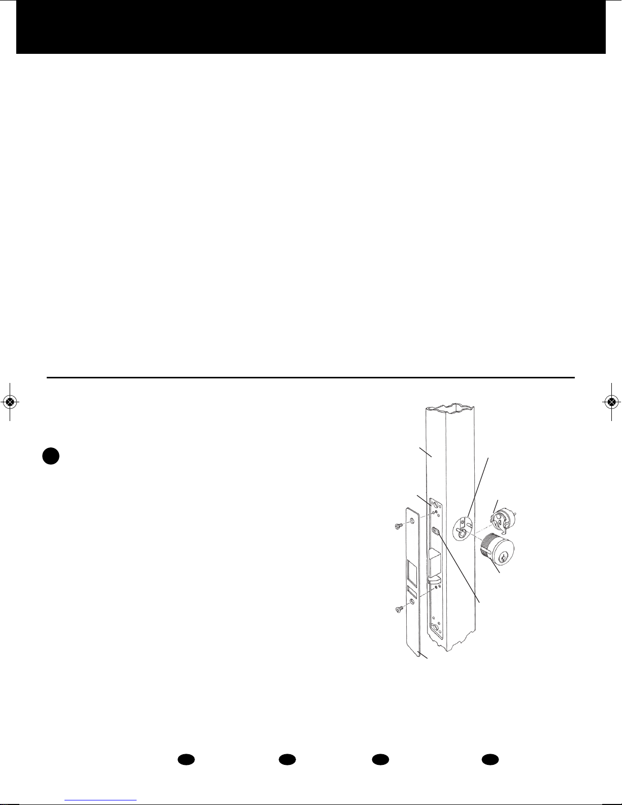
A HARDWARE DISASSEMBLY
A-1 Remove face plate from edge of door exposing
the cylinder set screws (See Figure 1).
A-2 Loosen the cylinder set screw (securing key
cylinder to latch) and remove the cylinder from
the dead latch assembly (See Figure 1).
A-3 With the exception of the dead latch assembly,
remove all other hardware from door: knob,
handle, etc (See Figure 1).
FIGURE 1
Narrow
Stile
Dead Latch
Assembly
Face Plate
Cam Plug in
Cylinder Hole
Cam Plug
Mortise
Cylindrical
Cylindrical
Set Screw
Page 2
Simplex Digital Lock
S
implex 3000 Drive Assembly - Instructions
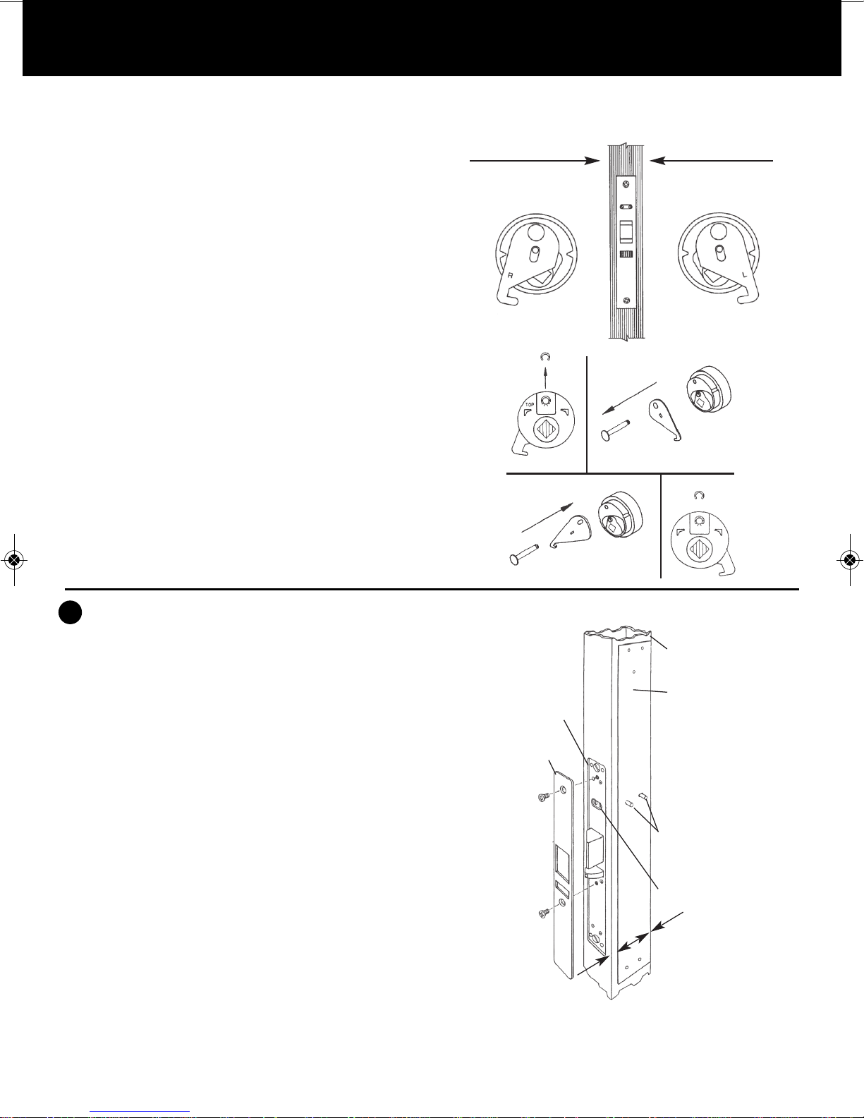
FIGURE 2
IF IT IS TO BE
THIS SIDE
THE CAM DISC
SHOULD BE HANDED
AS SHOWN BELOW
IF IT IS TO BE
THIS SIDE
THE CAM DISC
SHOULD BE HANDED
AS SHOWN BELOW
A
B
C
D
CAM PLUG HANDLING
A-4 Determine the required handing of cam disc on cam
plug (See Figure 2). Looking at the edge of the
door, determine on which side the lock is to be
installed.
If the cam disc handing needs to be changed,
proceed with steps A to D.
If not, proceed to Section B-1.
A. Remove the retainer clip from the pivot pin.
B. Pull the cam pivot pin out of the disc.
Note: Do not remove the driver piece.
C. Turn the cam over and push the cam pivot pin
through the cam and into the disc.
D. Reinstall the retainer clip onto the cam pivot pin.
B STILE PREPARATION FOR COMBINATION
SIDE OF DOOR
B-1 Install cam plug to the dead latch. Snug tighten the
cylinder set screw. See Section D-1 for final screw
adjustment (See Figure 1).
B-2 Position the cardboard template (locate on cam plug
pins) as shown (See Figure 3). Align template such
that it is parallel to the stile of the door.
Note: It may be necessary to further loosen the
cylinder set screw referred to in Section A-2
allowing movement of the template. Secure
template to the stile using tape.
B-3 Center punch templates holes marked A, B and C
(See Figure 3).
B-4 Carefully remove cardboard template (to be used
again in Section C-1). Drill pilot holes marked A, B
and C using a .094 (
3
⁄32") diameter drill bit (See
Figure 4).
Note: Drill through lock side of door only.
(Wear safety goggles when drilling).
FIGURE 3
Narrow
Stile
Dead Latch
Assembly
Face Plate
1 1⁄8" B.S.—R.H.
Part #64143
Cam Plug
Cardboard Template
31
⁄32" B.S.—R.H.
Part #64145
31
⁄32" B.S.— L.H.
Part #64146
1
⁄8" B.S.—L.H.
Part #64144
Cylindrical
Set Screw
Cardboard
Template
Parallel to
Stile
Combination Lock Side
A
A
Page 3

Simplex Digital Lock
S
implex 3000 Drive Assembly - Instructions
F
IGURE 4
N
Combination Lock Side
A
A
Narrow
Stile
Dead Latch
Assembly
Face Plate
Cam Plug
.094
3
⁄32"
Clear Drilled
Pilot Holes
.094
3
⁄32"
Clear Drilled
Pilot Holes
Cylindrical
Set Screw
FIGURE 5
Narrow
Stile
C
C
B
Trim Plate Side
Cam Plug Pins
Cylindrical
Set Screw
Cardboard
Template
Parallel to
Stile
A
A
C STILE PREPARATION OF TRIM PLATE SIDE OF
DOOR
(Trim plate assembly is included in lock housing box
marked 3001 or 3002).
C-1 Secure cam plug to the trim plate side of the dead latch
assembly.
Note: Installation of this cam plug will require the
opposite handing as used on the combination lock
side of the door. In the event opposite handing is
required, reverse cams as detailed in Section A.
C-2 Align and center punch holes using the cardboard
template as done in Sections B-2 and B-3 on the
combination lock side. Position the cardboard template
as shown (See Figure 5). (Make sure the inside trimplate
imprint of template is exposed.) Center punch A, B and C
holes. If obstructing hardware exist, cut cardboard
template to allow for flush seating against stile.
C-3 Remove cardboard template. Drill pilot holes marked A, B
and C using a .094 (
3
⁄32") diameter drill bit (See Figure
6).
D DRILL LOCK AND TRIM PLATE MOUNTING HOLES
D-1 Remove cam plug(s) and dead latch assembly from door
(See Figure 7). (This will prevent chips from entering the
latch.)
D-2 You are now ready to enlarge pilot holes marked A, B and
C on both sides of stile. Enlarge holes to sizes as follows:
(See Figure 7). Enlarge 2, holes marked A and 2 holes
marked C to a .375 diameter (
3
⁄8") drill bit (See Figure 5
& 6). Enlarge 1 hole marked B (See Figure 5 & 6) to a
.875 (
7
⁄8") drill bit. Make sure that all holes are deburred
prior to hardware assembly.
E HARDWARE ASSEMBLY
E-1 Re-install dead latch assembly. Re-install cam plug or
plugs (Do not tighten cylinder set screw) (See Figure 1).
E-2 Locate the drive assembly on lock side of door over the
pins on the cam plug. Secure lower portion of drive
assembly using two threaded sex bolts, two mounting
bushings and two 10-24 thd. x 13⁄4" (See Figure 8).
Tighten the cylinder set screw. Make sure the drive moves
freely up and down when holding latch depressed. Drive
should return freely to original position without the help
of the latch spring.
Page 4

Simplex Digital Lock
S
implex 3000 Drive Assembly - Instructions
01202 676 2 6 2
0 1 2 0 2 6 8 0 1 0 1
alp ro@iecl td.co.u k
w w w. a l p r o . c o . u k
T
F
E
W
IEC Limited
Harwell Road Nuffield Estate Poole Dorset BH17 0BD Great Britain
Registered in England & Wales 1925537
© June 2009 IEC. All rights reserved.
All dimensions are nominal and subject to tolerances
FIGURE 6
FIGURE 5
Narrow
Stile
A
A
C
C
B
C
C
B
Trim Plate Side
Trim Plate Side
Cam Plug Pins
.094
3
⁄32"
Pilot Holes
.094
3
⁄32"
Pilot Holes
7
⁄8" Clear
Drilled Hole
3
⁄8" Clear
Drilled Hole
Cylindrical
Set Screw
Cylindrical
Set Screw
Cardboard
Template
P
arallel to
Stile
A
A
FIGURE 7
A
A
C
C
B
.094
3
⁄32"
P
ilot Holes
.094
3
⁄32"
P
ilot Holes
.250
1
⁄4"
Clear
Drilled
Holes
7
⁄8" Clear
Drilled Hole
3
⁄8"
Clear
Drilled Hole
Combination Lock Side
F
IGURE 7
FIGURE 8
A
A
C
C
B
.
094
3
⁄32"
Pilot Holes
.094
3
⁄32"
Pilot Holes
.
250
1
⁄4"
C
lear
Drilled
H
oles
7
⁄8" Clear
D
rilled Hole
3
⁄8" Clear
Drilled Hole
Housing
Locator
Stud
Dead Latch
Assembly
Face Plate
Cam Plug
Pins
#74xxx
Drive Assembly
(Sample
Illustration)
Mounting
Bushings (2)
Mounting Screws
As shown on each Drive Assembly
•
31
⁄32" B.S.—L.H. Drive
Assembly Part #74422
•
31
⁄32" B.S.—R.H. Drive
Assembly Part #74420
• 1
1
⁄8" B.S.—L.H. Drive
Assembly Part #74418
• 1
1
⁄8" B.S.—R.H. Drive
Assembly Part #74416
Cylindrical
Set Screw
Threaded
Sex Nuts (2)
Combination Lock Side
Combination Lock Side
 Loading...