

Page 1
Page 2
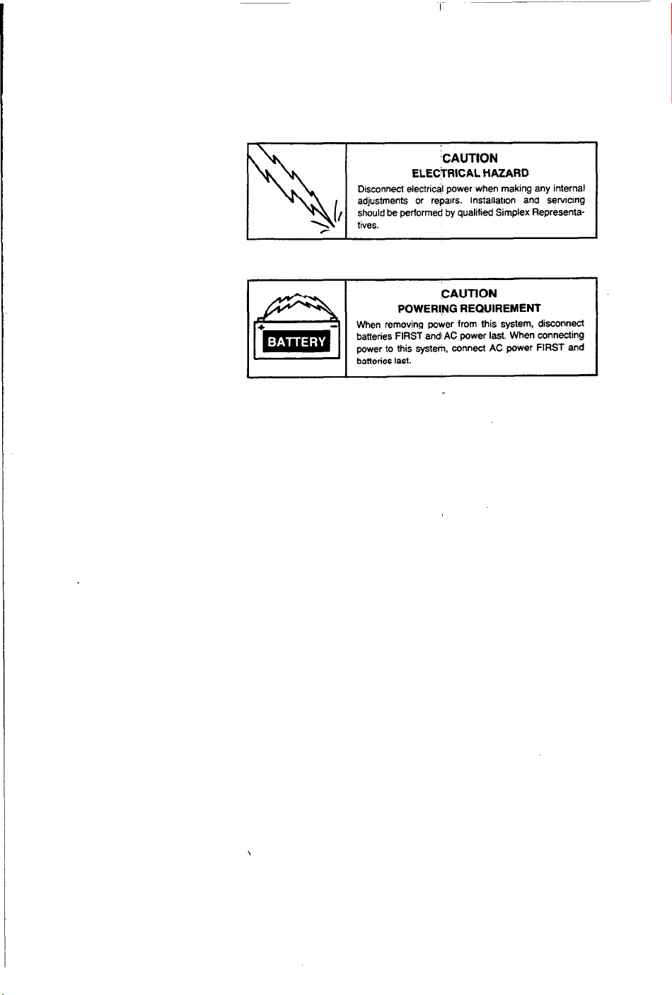
CAUTION
ELECiRlCAL HAZARD
Disconnect electrical power when making any internal
adjustments or rebairs. Installation and servicing
should be performed by qualified Simplex Representatives.
CAUTION
POWERING REQUIREMENT
When removing payer from this system, disconnect
batteries FIRST and1 AC power last. When connecting
power to this system. connect AC power FIRST and
batteries last.
Page 3
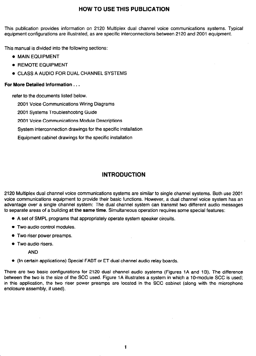
HOW TO USE THIS PUBLICATION
This publication provides information on 2120 Multiplex dual channel voice communications systems. Typical
equipment configurations are illustrated, as are specific interconnections between 2120 and 2001 equipment.
This manual is divided into the following sections:
l
MAIN EQUIPMENT
l
REMOTE EQUIPMENT
l
CLASS A AUDIO FOR DUAL CHANNEL SYSTEMS
For More Detailed lnformation . . .
refer to the documents listed below.
2001 Voice Communications Wiring Diagrams
2001 Systems Troubleshooting Guide
2001 Voice Communications Module Descriptions
System interconnection drawings for the specific installation
Equipment cabinet drawings for the specific installation
INTRODUCTION
2120 Multiplex dual channel voice communications systems are similar to single channel systems. Both use 2001
voice communications equipment to provide their basic functions. However, a dual channel voice system has an
advantage over a single channel system: The dual channel system can transmit two different audio messages
to separate areas of a building at the same time. Simultaneous operation requires some special features:
l
A set of SMPL programs that appropriately operate system speaker circuits.
l
Two audio control modules.
l
Two riser power preamps.
l
Two audio risers.
AND
l
(In certain applications) Special FABT or ET dual channel audio relay boards.
There are two basic configurations for 2120 dual channel audio systems (Figures 1A and 1B). The difference
between the two is the size of the SCC used. Figure 1A illustrates a system in which a lo-module SCC is used;
in this application, the two riser power preamps are located in the SCC cabinet (along with the microphone
enclosure assembly, if used).
Page 4

-w------------w------,
r
I
,I sf$;ES TRANSFORMER 1 ,
-----------------
r
AUDIO IN TO EACH
lNOlVlDUALAUDlORELAV
I I
FABT
CONTROLLER
BOARD
AUDIO
RELAY
BOARD
INTERFACE
I
REMOTE
AMPLIFIER
I I
1
I
TO OTHER
VPBTS IN
L
-THE SAME
L--------------------4
CABINET
I
CABINET
COMMUNICATIONS II
SPEAKER
CIRCUITS
BMUX AND SCC CABINETS
CLOSE-NIPPLED (SIDE BY SIDE).
BMUX see
DUAL VOICE
EOUIPMENT
n
‘1’
. AUDIO
HARNESS
TYPE t
TRAiSFORMER
CABINET (VPBT)
CABINET
-----
r
I
EVACUATE ALERT
POWER POWER
PREAMP PREAMP
EVACUATE
AUDIO
RISER
"
17
{’
ALERT
AUDIO
RISER
2120 Dual Channel Voice Communications Block Diagram
(1 O-Module SCC Only)
FIGURE 1 A
2
Page 5

Figure 1B illustrates an application in which a 30-module SCC is used. If that SCC contains a microphone
enclosure assembly, then the two riser power preamps must be mounted in a close-nippled transponder cabinet.
_--_-__--------
r-
_______ ----------,
l-
I
I
L---------------------
CABWET
-----1
I
.i
2120 Dual Channel Voice Communications Block Diagram
(304odule SCC Only)
FIGURE 1 B
Let’s look at the various components of the 2120 dual channel audio system. We’ll start with the main equipment.
Throughout this publication we will use 2001 product identification numbers for voice
communication equipment to make it easier for you to cross-reference 2001 voice
communications documentation.
I
3
Page 6
MAIN EQUIPMENT
This section discusses the dual channel audio equipment used in the BMUX, SCC, and riser preamp cabinets,
and the interconnections between that equipment and 2120 equipment.
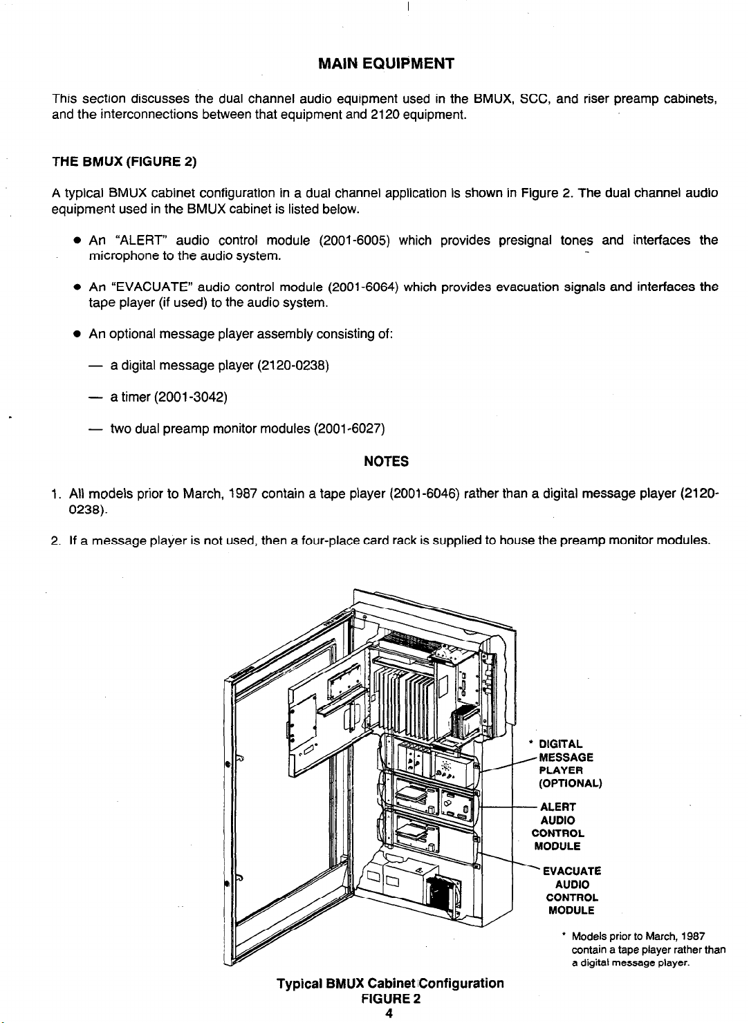
THE BMUX (FIGURE 2)
A typical BMUX cabinet configuration in a dual channel application is shown in Figure 2. The dual channel audio
equipment used in the BMUX cabinet is listed below.
l
An “ALERT” audio control module (2001-6005) which provides presignal tones and interfaces the
microphone to the audio system.
l
An “EVACUATE” audio control module (2001-6064) which provides evacuation signals and interfaces the
tape player (if used) to the audio system.
l
An optional message player assembly consisting of:
- a digital message player (2120-0238)
- a timer (2001-3042)
- two dual preamp monitor modules (2001-6027)
NOTES
1. All models prior to March, 1987 contain a tape player (2001-6046) rather than a digital message player (2120-
0238).
2. If a message player is not used, then a four-place card rack is supplied to house the preamp monitor modules.
l
DIGITAL
, MESSAGE
PLAYER
(OPTIONAL)
- ALERT
AUDIO
CONTROL
MODULE
’ EVACUATE
AUDIO
CONTROL
MODULE
Typical BMUX Cabinet iconfiguration
FIGURE 2
4
l
Models prior to March, 1987
contain a tape player rather than
a digital message player.
Page 7

Figures 3 through 5 illustrate the interconnections between each dual channel audio component and the BMUX
equipment. Notice that the local BT is u&d to implement various audio functions, just as it is in the single channel
audio system.
AUDIO SYSTEM TROUBLE
FROM PREAMP MONITORS
TO LOCAL BT MONITOR
>
POINT 7
EVAC PREAMP
MONITOR
1
ALERT (TALK)
PREAMP MONITOR
+V IN FOR
AUDIO TROUBLE
RESET FROM
OSCILLATOR
CONTROL SWITCH
MODULE IN SCC
CABINET
+ V IN FROM
LOCAL BT CONTROL
POINT 1 TO ACTIVATE
I
AUDIO SYSTEM -
l-l-
Pl
TIMER
2
3 4
EVAC AUDIO CONTROL MODULE
OV FOR & J STOP TO
MESSAGE
(OR TAPE)
PLAYER
_, MESSAGE (OR TAPE)
1.
AJDIO
OUT
TOEVACUATE
AUDIO CONTROL
MODULE
MESSAGE (OR TAPE) RESET
FROM LOCAL BT
CONTROL POINT 2
Note: Refer to 2001 Systems
Troubleshooting Guide
and BMUX cabinet
drawing for 2001
module interconnections
not shown here.
Message Player Assembly
FIGURE 3
Page 8
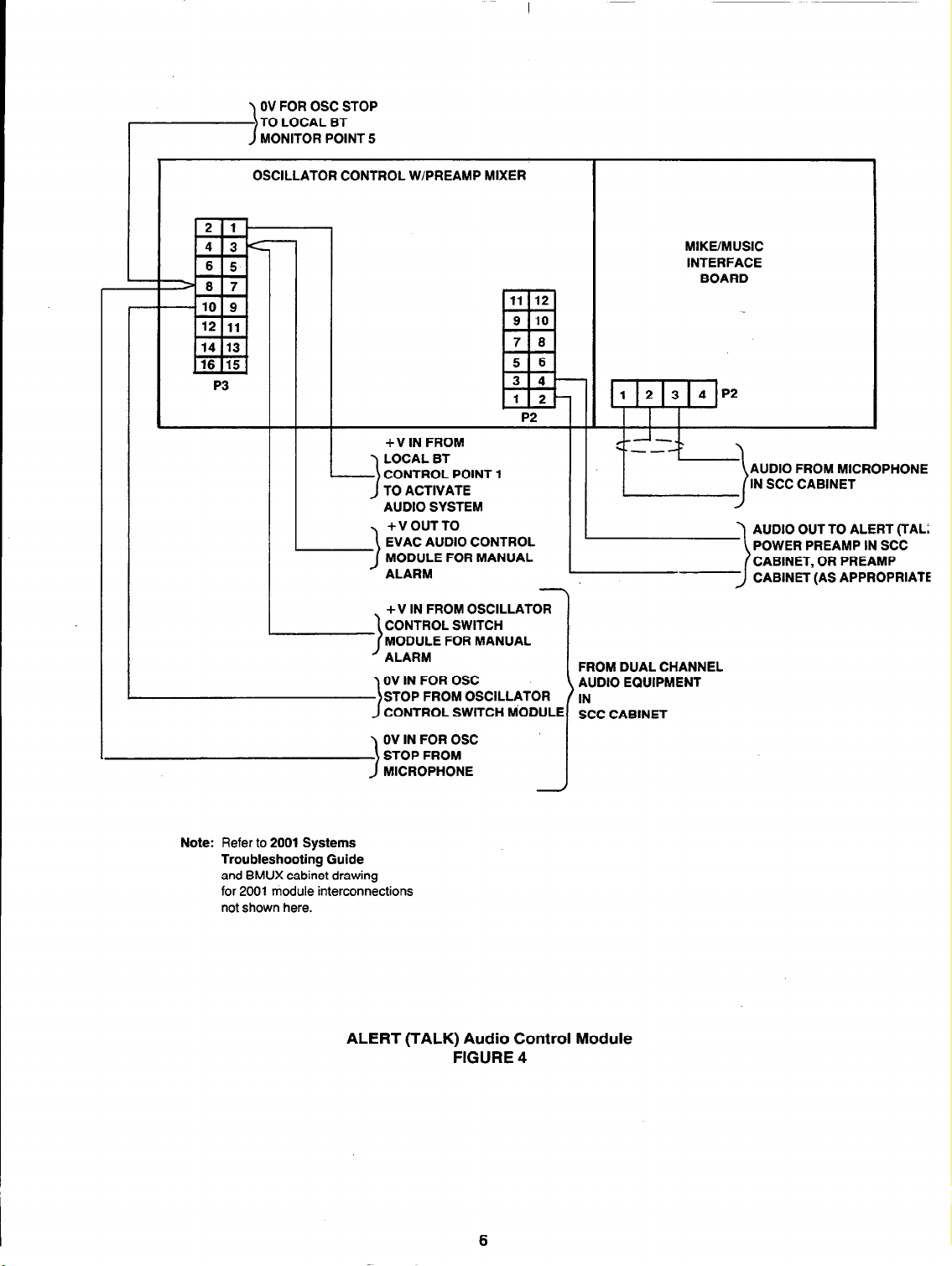
OV FOR OSC STOP
TO LOCAL BT
MONITOR POINT 5
>
OSCILLATOR CONTROL WlPREAMP MIXER
P3
MIKE/MUSIC
INTERFACE
BOARD
I
I
Note: Refer to 2001 Systems
Troubleshooting Guide
and BMUX cabinet drawing
for 2001 module interconnections
not shown here.
P2
. +V IN FROM OSCILLATOR
CONTROL SWITCH
MODULE FOR MANUAL
’ ALARM
OV IN FOR OSC
STOP FROM OSCILLATOR
CONTROL SWITCH MODULE
>
OV IN FOR OSC
STOP FROM
MICROPHONE
I I I I
I I
-
FROM DUAL CHANNEL
AUDIO EQUIPMENT
IN
SCC CABINET
CABINET, OR PREAMP
CABINET (AS APPROPRIATE
ALERT (TALK) Audio Control Module
FIGURE 4
6
Page 9

OSCILLATOR CONTROL W/PREAMP MIXER
.-I,-~
6 5
10 9
12 11
14 13 -
16 15
-8 7
P3
+ V IN TO ACTIVATE
AUDIO SYSTEM FROM LOCAL BT
CONTROL POINT 1
+ V IN FOR MANUAL ALARM
FROM OSCILLATOR CONTROL SWITCH MODULE
IN SCC CABINET (VIA ALERT AUDIO CONTROL MODULE)
11 12
9 10
7 8
5 6
3 4
1 2
EL-
P2
+V IN FROM AUX. 1 TONE
FROM OSCILLATOR CONTROL
SWITCH MODULE
AUDIO OUT TO
EVAC POWER
APPROPRIATE)
Note: Refer to 2001 Systems
Troubleshooting Guide and
BMUX cabinet drawing
for 2001 module interconnections
not shown here.
+ V IN FOR AUX. 2 TONE
FROM OSCILLATOR CONTROL
SWITCH MODULE
OV IN FOR OSC STOP
FROM OSCILLATOR CONTROI
SWITCH MODULE
>
OV IN FOR OSC STOP
FROM MESSAGE (OR TAPE) PLAYER
>
EVACUATE Audio Control Module
FIGURE 5
FROM DUAL CHANNEL
AUDIO EQUIPMENT
IN SCC CABINET
c
Page 10

Figure 6 shows two typical transponder specification sheets for the local BT, listing the functions of local BT
monitor and control points in a dual channel audio system.
SSimplex
TRANSPONDER SPECIFICATION WORKSHEET
NO ll-2)-
NDER NO ,1-63~-
NDER TYPE ,PROD ID!
I CHANNEL No ~1.21~
2 TRANSPONDER NO 11.631-
da) 11 ;;N’ 11 CUSTOM LABE
2120 TRANSPONDER CONTINUATION SPECIFICATION SHEET
channe
Typical Transponder Specification Worksheets
for Local BT Dual Channel Voice Comm. Functions
FIGURE 6
8
Page 11

THE SCC (FIGURE 7)
The typical SCC cabinet configuration in a 2120 dual channel voice communications system is shown in Figure
7. The dual channel audio equipment used in the SCC cabinet is listed below.
l
A dual power preamp assembly (2001-6063).
0 A microphone enclosure assembly (2001-6030), consisting of a microphone panel and an oscillator control
switch module for dual channel audio applications (2001-6065). (Instead of an ALL CIRCUITS switch, this
oscillator control switch module has a three-position ALL TALK/OFF/ALL EVAC switch.)
0 One or more three-position maintained SCC switch modules (2120-731 l), used for speaker circuit selection
(center position = automatic; up position = ALERT; down position = EVACUATE).
Note: If a fire fighter’s phone is used in a 30-module SCC, then the dual preamp assembly mounts in a close-
nippled transponder cabinet. Interconnections, however, remain the same.
Typical SCC Cabinet Configuration
FIGURE 7
FIRE FIGHTER’S
,TELEPHONE
ASSEMBLY
MICROPHONE
.ENCLOSURE
ASSEMBLY
9
Page 12
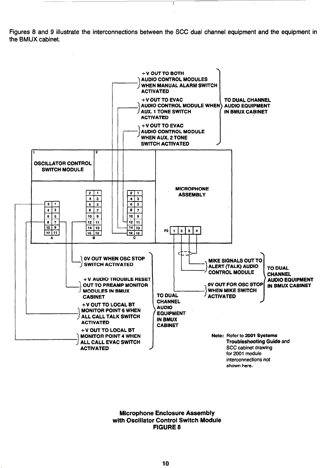
Figures 8 and 9 illustrate the interconnections between the’ SCC dual channel equipment and the equipment in
the BMUX cabinet.
+ V OUT TO BOTH
AUDIO CONTROL MODULES
WHEN MANUAL ALARM SWlTCH
ACTIVATED
+ V OUT TO EVAC
AUDIO CONTROL MODULE WHEI
AUX. 1 TONE SWITCH
ACTIVATED
+ V OUT TO EVAC
AUDIO CONTROL MODULE
WHEN AUX. 2 TONE
SWITCH ACTIVATED
OSCILLATOR CONTROL
SWITCH MODULE
I III
MICROPHONE
ASSEMBLY
1
TO DUAL CHANNEL
AUDIO EQUIPMENT
IN BMUX CABINET
/
OV OUT WHEN OSC STOP
SWITCH ACTIVATED
+ V AUDIO TROUBLE RESEl
OUT TO PREAMP MONITOR
MODULES IN BMUX
CABINET
+ V OUT TO LOCAL BT
MONITOR POINT 6 WHEN
ALL CALL TALK SWlTCH
>
ACTIVATED
+ V OUT TO LOCAL BT
f%YEzzll~:
ACTIVATED
Microphone Enclosure Assembly
with Oscillator Control Switch Module
lN BMUX CABINET
AUDIO
EQUIPMENT
IN BMUX
CABINET
Note: Refer to 2001 Systems
Troubleshooting Guide and
SCC cabinet drawing
for 2001 module
interconnections not
shown here.
FIGURE 8
10
Page 13

l-7
AUDIO SIGNAL IN
FROM TALK AUDIO
CONTROL MODULE IN
BMUX CABINET
AUDIO SIGNAL IN FROM
EVAC AUDIO CONTROL
MODULE IN BMUX CABINET
PREAMP
TBl
\I
TALK AUDIO RISER
OUT TO TRANSPONDERS
VIA CONTRACTOR
TERMINAL BLOCK
1. Refer to your system’s interconnection diagram for
2. Riser preamps only mount in lo-module SCCs; if a
3. Refer to 2001 Systems Troubleshooting Guide
ALERT
(TALK)
RISER
p\ __
Ii __-
1
I ’
NOTES
audio riser terminations.
30-module SCC is used, then the preamps mount
in a separate cabinet close-nippled to the SCC or
BMUX cabinet.
and appropriate cabinet drawing for 2001 module
interconnections not shown here.
SIG IN
-0v
. -0v
+24-
2
1
TBl
I
EVAC AUDIO RISER
OUT TO TRANSPONDERS
VIA CONTRACTOR
TERMINAL BLOCK
EVACUATE
RISER
PREAMP
TALK and EVACUATE Riser Preamps
FIGURE 9
11
Page 14

REMOTE EQUIi’MENT
This section deals with the dual channel voice communications equipment used in FABT and ET cabinets and how
that equipment is tied into the two 2120 audio risers. There are two FABT and ET cabinet configurations in dual
channel audio systems.
TYPE 1 TRANSPONDER CABINETS
All speaker circuits in a Type 1 transponder cabinet use either the “ALERT” audio signal or the “EVACUATE”
audio signal -
(A) Contain one or more VPBTs.
(B) Consist of an ET containing standard audio relay boards.
Note: The abbreviation “VPBT” (voice/phone basic transponder) refers to an FABT containing standard audio
relay boards.
The VPBT
VPBTs in a Type 1 configuration are almost identical to VPBTs in a standard audio application. Two extra
components are used in the Type 1 VPBT cabinet:
BUT NOT BOTH. A Type 1 transponder cabinet could either:
OR
l
An audio interface transformer/relay switcher (617-221), which performs two functions:
-
It interfaces the incoming audio signal to the cabinet’s audio amplifier.
AND
-
It selects which audio riser signal will be used by the speaker circuits in the associated VPBT(s). (The
switching relay is operated by a transponder control point via SMPL programming.)
l
An audio riser monitor (562-125) and associated mounting hardware, The monitor is required only when a
Type 1 VPBT cabinet is electrically the last in line on the audio risers. The audio riser monitor supervises
the ALERT riser for opens or shorts. A transponder monitor point is used to supervise the audio riser
monitor’s trouble output.
Except for these two differences, VPBTs in standard and Type 1 applications are identical. Figure 10 shows how
the audio interface transformer/relay switcher and the audio riser monitor tie into the dual channel audio risers.
The ET
ETs in a Type 1 configuration are almost identical to ETs in a standard audio application. The difference between
the two are the same as the differences that exist between the standard and Type 1 VPBTs. In fact, both the Type
1 VPBT and Type 1 ET use the same dual channel audio components. Figure 10 shows how the audio interface
transformer/relay switcher and the audio riser monitor tie into the dual channel audio risers.
12
Page 15

r
I I.. I
\ FROM TALK
AUDIO RISER
(SEE NOTE)
I@ Mz II I A
II I+24
1
REMOTE
AUDIO
AMPLIFIER
I
!i
I
I
i lEtI
TO VPBT OR
ET CONTROL
POINT VIA
. . . -...-I1
FROM EVAC
AUDIO
>
RISER
AUDIO INTERFACE
\
TRANSFORMER/RELAY
SWlTCHER
Note: In the last Type 1 VPBT or ET cabinet in the
system, the TALK audio riser will be
supervised by an audio riser monitor. In such
cases, the TALK audio riser will be factotywired to the audio riser monitor and from there
connected to the interface transformer/relay
switcher.
Remote Amplifier Connections
FIGURE 10
13
Page 16
TYPE 2 TRANSPONDER CABINETS
The speaker circuits in a Type 2 transponder cabinet use the signals on both audio risers to provide “ALERT”
and “EVACUATE” tones to different building areas simultaneously. For example, suppose the speaker circuits for
floors 1, 2, and 3 in a building were controlled by equipment in a Type 2 transponder cabinet. An EVACUATE
signal could then be sent out over the second floor speaker circuit, and an ALERT signal could be sent out on
the first and third floor speaker circuits AT THE SAME TIME. Appropriate equipment and SMPL programming
make the system work as required.
A Type 2 transponder cabinet could either:
(A) Contain one or more DABTs.
OR
(B) Consist of an ET containing simultaneous audio relay boards.
Note: The abbreviation “DABT” (dual audio basic transponder) refers to an FABT that uses a dual audio relay
board.
The DABT (Figure 11)
The DABT is quite different from any VPBT because it is designed for a Type 2 application. It uses equipment
different from that used in a VPBT. The typical DABT cabinet contains the equipment listed below.
l
A dual 50W amplifier (2001-6063) one amplifier for each audio riser.
l
Two audio interface transformers (2001-6056) one for each audio amplifier.
l
One or more dual audio relay boards (562-590).
Each DABT in a Type 2 cabinet provides:
l
Five monitor points.
l
A smoke reset output (for resetting 4-wire smoke detectors).
l
One simultaneous audio control point.
l
One control point used for selecting ALERT or EVACUATE signals.
0 One auxiliary control point.
Note: The auxiliary control point provides normally open dry contacts. It can be used as another simultaneous
audio control point, but both simultaneous audio control points on the same DABT must use the same
signal (either ALERT or EVACUATE) if two speaker circuits per floor are necessary.
Figure 12 illustrates how the DABT voice communications equipment is tied into each audio riser.
14
Page 17

TALK REMOTE
AMPLIFIER WlTH
AUDIO INTERFACE
TRANSFORMER
EVACUATE REMOTE
AMPLIFIER WITH
-AUDIO INTERFACE
TRANSFORMER
Typical DABT Cabinet Configuration
FIGURE 11
15
Page 18

TALK
AUDIO
RISER
EVAC
AUDIO
RISER
‘
I
J&
TALK
Al ,n,rr
rn”Yl”
RISER
OUT
AUDIO
INTERFACE Muy’” “:‘:
TRANSFORMER
AI #ml,.
DUAL AUDIO RELAY
BOARD (DABTS,
SIMULTANEOUS
AUDIO RELAY BOARD
(ETS, 562406)
/I
13
562-590)
OR
TALK AMP
I
+ V OUT FOR
AMP TBL; TO DABT
OR ET MONITOR POINT
FOR TROUBLE REPORT
AUUK
- “-‘-I SIGNAL OUT
DUAL AUDIO RELAY
BOARD (DABTS,
SIMULTANEOUS
AUDIO RELAY BOARD
_--_
TO
562~i90)
OR
(ETS, 562-506)
EVAC AMP
IN DABT
OR ET
CARINFT
I
+ V OUT FOR
AMP TBL; TO DABT
OR ET MONITOR POINT
FOR TROUBLE REPORT
d-J
J
I I
I I
\c
EVAC
AUDIO
RISER
ml1
--.
Dual Amplifier Connectlons
FIGURE 12
Page 19

The ET (Figure 13)
The ET in a Type 2 application is shown in Figure 13. The dual channel audio equipment used in the Type 2 ET
cabinet is listed below.
l
A dual 50W amplifier (2001-6063), one amplifier for each audio riser.
l
Two audio interface transformers (2001-6056) one for each audio amplifier.
l
One or more simultaneous audio relay I/O boards (562-508).
Figure 12 illustrates how the ET voice communications equipment is tied into each audio riser.
TALK REMOTE
AMPLIFIER WITH
AUDIO INTERFACETRANSFORMER
EVAC REMOTE
AMPLIFIER WITH
AUDIO INTERFACE
TRANSFORMER
Page 20

CLASS A AUDIO FOR DUAL CHANNEL SYSTEMS
This section discusses how we provide Class A audio operation for 2120 dual channel audio systems.
To provide Class A operation, all we need do is add a Class A audio monitor (562-125, Figure 14) for each of
our audio risers. There are two versions of the Class A audio monitor; the only difference between the two is the
way in which they are mounted. Both Class A audio monitors mount in the SCC cabinet as shown in Figure 15.
Class A Audio Monitor, 562-l 25
FIGURE 14
Figure 16 illustrates in block diagram form how the Class A monitor works. (For clarity, only one audio riser is
shown.) Each audio monitor simply “looks at” the end of its audio riser to ensure that the audio signal is being
received by all remote amplifiers. A break in the audio riser results in a loss of audio at the audio monitor, and
so its internal relay (Kl) simply deenergizes to allow the audio signal to be fed from both ends of the audio riser.
Thus, all remote amplifiers still receive the audio signal. Local BT monitor point 3 is used to supervise the audio
monitors and report Class A activation.
The interconnections for each Class A audio monitor are shown in Figure 17.
16
Page 21

MOUNTING LOCATION
FOR EVACUATE CLASS A
AUDIO MONITOR
(SAME AS AUDIO
INTERFACE TRANSFORMER
ON REMOTE AMPLIFIERS).
CONTRACTOR CONNECTOR
BLOCK AND BRACKET
WHERE CLASS A AUDIO
-MONlTOR FOR THE
ALERT AUDIO RISER
MOUNTS*
‘IF DUAL PREAMPS
ARE IN A SEPARATE
CABINET, THE CLASS A
AUDIO MONITORS WILL
BE LOCATED THERE.
SCC Cabinet,
Class A Audio Monitor Mounting Location
FIGURE 15
19
Page 22

I
I
CLASS
A
AUDIO
MONITOR
I
Note: Only one monitor and audio
riser shown for clarity.
1
lr--j ii&z
1
Class A Audio Block Diagram
REMOTE
REMOTE
AMP ,,
I I
I I
FIGURE 16
END OF
AUDIO_l?ISER
,
+ 24V
AUDIO RESET
FROM MIKE
ENCLOSURE
ASSEMBLY IN
BMUX (VIA HARNESS
Note: Only evacuate monitor is shown here; connections for alert monitor are identical.
-)
(
9
TBL OUT TO LOCAL BT
TBl
B
POWER
PREAMP
AUDIO OUT
1
c
TO RISER
)I VIA CONTRACTOR
TERMINAL BLOCK
Class A Audio Monitor
Interconnections
FIGURE 17
20
Page 23

Page 24

Y
Ed 3 87
I
Simplex Time Recorder Co.. 0 Simplex Plaza l Gardner. Massachusetts 01441-0001 U.S.A.
MUX2-11-004
 Loading...