

Simplex 2100, 2120 Installation Instructions Manual
-a
,Simplex
210012120
Multiplex Interface
Installation Instructions
DESCRIPTION
Printed Circuit Boards
A 2100/2120 interface Kit is required for each 2100 transponder which will be required to communicate with a
2120 BMUX. This kit consists of two printed circuit boards which will replace the 2100 Transmission and the
Controller boards in the 2100 transponder. The new Communications board can be identified by two yellow and
one red LED on the outside edge of the board. The new Controller board has a single green LED on it and also
contains an 87C51 microcontroller IC.
Transient Protection
A Simplex Model 2081-9027 Isolated Loop Circuit Protector is required on both sides of any communications line
that leaves the building.
Distance Restrktions
If the 2100 transponder is located more than 10,000 feet (1.9 miles) from the BMUX, a DC repeater or a modem
is required.
Related Documents
1. 2100 Multiplex Transponder Parts List MUX1 -81-002
2. 2100 Multiplex Installation Instructions 575-544
INSTALLATION PROCEDURES
Transponder Preparation
1.
2.
3.
4.
5.
Disconnect the AC power and batteries from all
transponders.
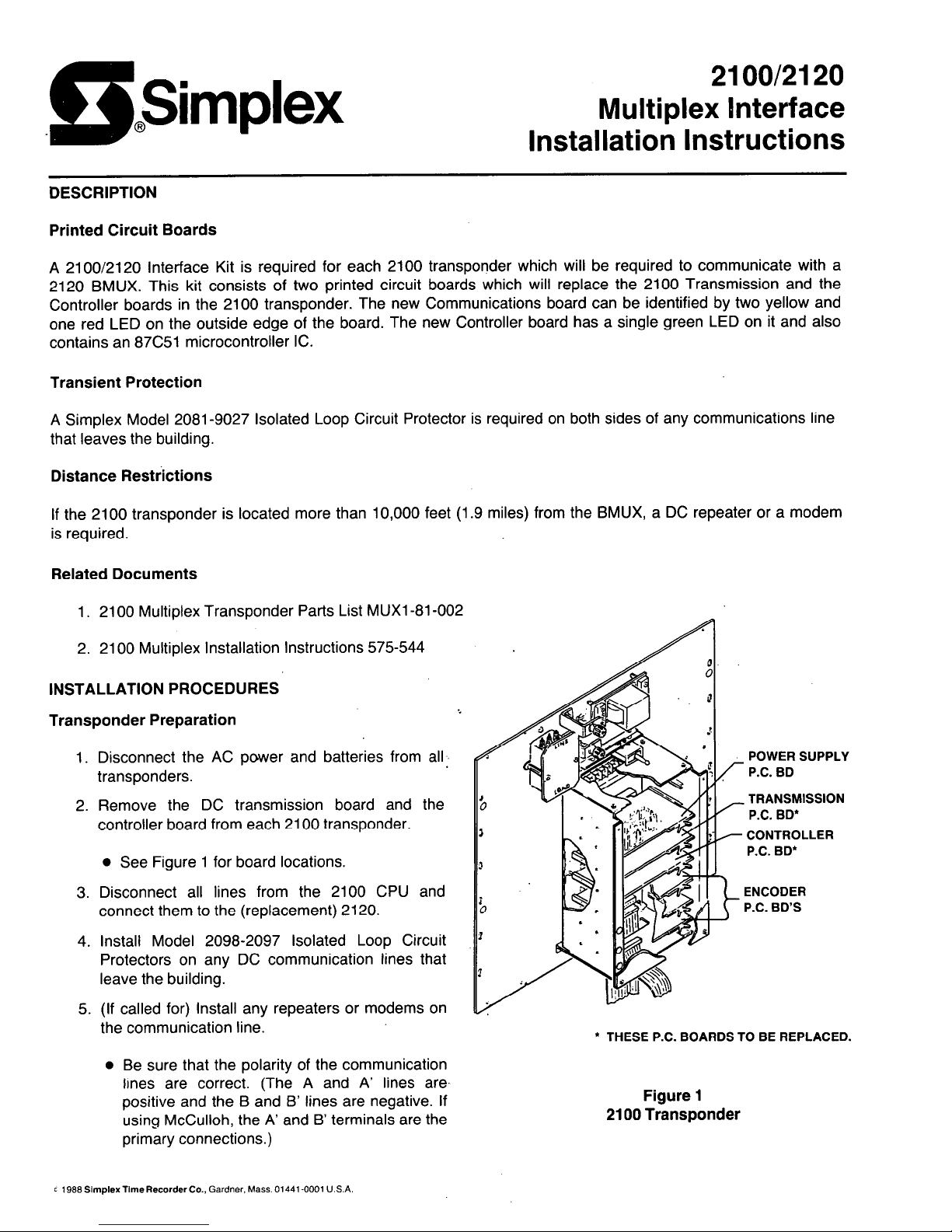
Remove the DC transmission board and the
controller board from each 2100 transponder.
l
See Figure 1 for board locations.
Disconnect all lines from the 2100 CPU and
connect them to the (replacement) 2120.
Install Model 2098-2097 Isolated Loop Circuit
Protectors on any DC communication lines that
leave the building.
(If called for) Install any repeaters or modems on
the communication line.
l
Be sure that the polarity of the communication
lines are correct. (The A and A’ lines are
positive and the B and B’ lines are negative. If
using McCulloh, the A’ and B’ terminals are the
primary connections.)
POWER SUPPLY
P.C. BD
TRANSMISSION
P.C. BD”
CONTROLLER
P.C. BD*
ENCODER
P.C. BD’S
l
THESE P.C. BOARDS TO BE REPLACED.
Figure 1
2100 Transponder
c 1999SimplexTime Recorder Co., Gardner. Mass. 01441-0001 U.S.A.
Technical Manuals Online! - http://www.tech-man.com
PC Board Preparation
IMPORTANT: Use the Anti-static Kit (Part No. 553-503) when handling these boards.
Communications Board
If not operated in McCulloh (style 7) no alterations need to be made to the board. If operated in style 7, contact
Service Support at Headquarters.
Controller Board
There are three banks of dip switches on the controller board which must be configured properly for the
transponder to operate. These switch banks are read and stored by the microcontroller upon power up or when
the RESET button is pressed. If the settings are changed once the transponder is powered up, the RESET
button must be pressed or the power must be removed and re-applied for the new settings to be read and
stored.
Encoder Card Address Switch Settings (SW1 and SW2)
Dip switches on switch banks SW1 and SW2 are numbered 0 to 15 and are set ON if their number corresponds
to an encoder card address present in the transponder. These addresses are found by either (a) looking them up
on the 2100 TRANSPONDER SPECIFICATION SHEETS for the particular job being converted or by (b) reading
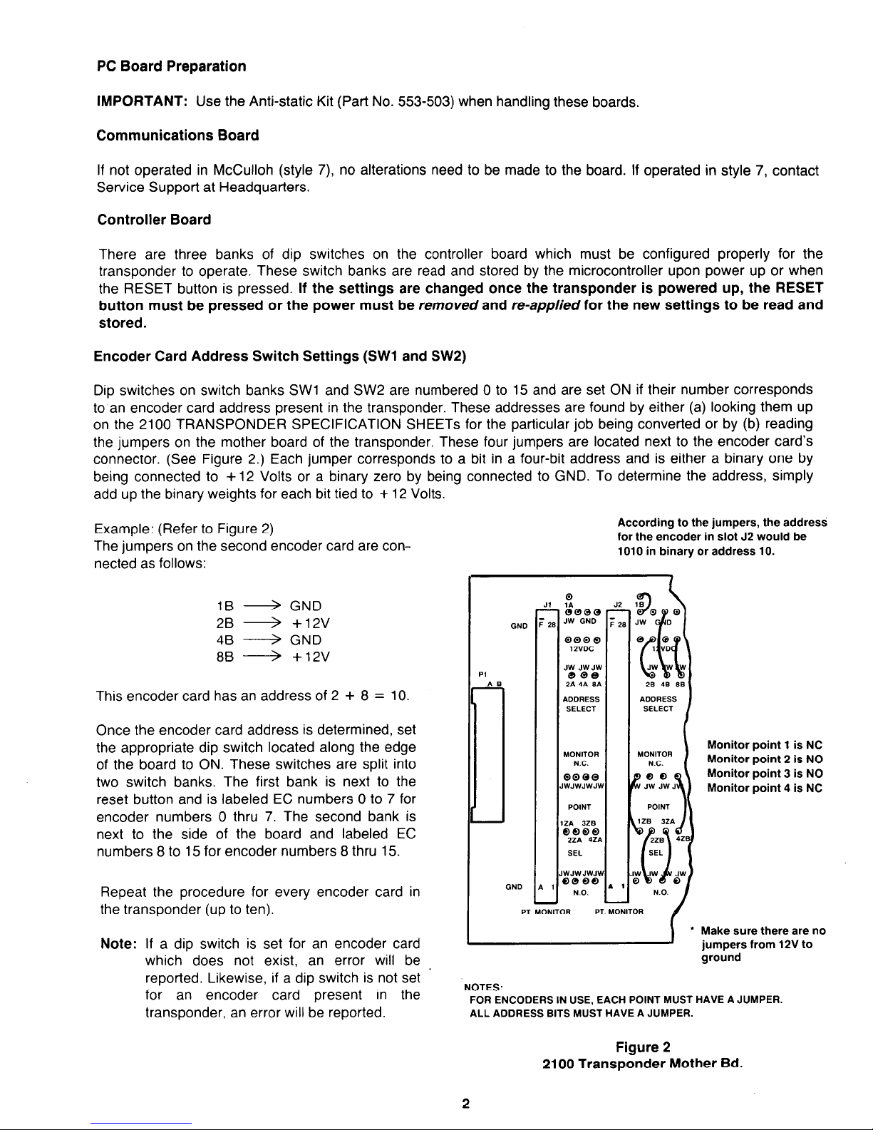
the jumpers on the mother board of the transponder. These four jumpers are located next to the encoder card’s
connector. (See Figure 2.) Each jumper corresponds to a bit in a four-bit address and is either a binary one by
being connected to + 12 Volts or a binary zero by being connected to GND. To determine the address, simply
add up the binary weights for each bit tied to + 12 Volts.
Example: (Refer to Figure 2)
The jumpers on the second encoder card are con-
nected as follows:
1B 4 GND
28 + +12V
48 --+ GND
88 --+ +12v
This encoder card has an address of 2 + 8 = 10.
Once the encoder card address is determined, set
the appropriate dip switch located along the edge
of the board to ON. These switches are split into
two switch banks. The first bank is next to the
reset button and is labeled EC numbers 0 to 7 for
encoder numbers 0 thru 7. The second bank is
next to the side of the board and labeled EC
numbers 8 to 15 for encoder numbers 8 thru 15.
Repeat the procedure for every encoder card in
the transponder (up to ten).
Note: If a dip switch is set for an encoder card
which does not exist, an error will be
reported. Likewise, if a dip switch is not set ’
for an encoder card present in the
transponder, an error will be reported.
According to the jumpers, the address
for the encoder in slot J2 would be
1010 in binary or address 10.
ON0
J1
. 28
1
QQQQ
1 NOC
MONITOR
NC.
QQQQ
~WJWJV~JV
POINT
IZA 328
66QQ
2ZA 4241
SEL
WJWJWJV
6088
NO.
Monitor point 1 is NC
Monitor point 2 is NO
Monitor point 3 is NO
Monitor point 4 is NC
* Make sure there are no
jumpers from 12V to
ground
NOTES:
FOR ENCODERS IN USE, EACH POINT MUST HAVE A JUMPER.
ALL ADDRESS BITS MUST HAVE A JUMPER.
Figure 2
2100 Transponder Mother Bd.
Technical Manuals Online! - http://www.tech-man.com
 Loading...