

Page 1
Zeus Ultra DMA Solid State Drive
Product Information Datasheet
The information in this document is private to SimpleTech, Inc., and shall not be used, copied, reproduced,
or disclosed, in whole or in part, without the written consent of SimpleTech, which can only be granted by
the Product Manager responsible for this product.
Page 2

Export Administration Regulation
This document may contain technical data controlled by the U.S. Export Administration Regulations, and
may be subject to the approval of the U.S. Department of Commerce prior to export. Any export, directly or
indirectly, in contravention of the U.S. Export Administration Regulation is prohibited.
Trademark Information
The SimpleTech name, logo and design are trademarks of SimpleTech, Inc. No right, license, or interest to
such trademarks is granted hereunder, and you agree that no such right, license, or interest shall be asserted
by you with respect to such trademark.
Other product and corporate names mentioned in this document are used for identification purposes only
and may be trademarks or registered trademarks of their respective companies.
Disclaimer of Liability
The performance information and specifications furnished in this document reflect SimpleTech’s
engineering development objectives and should be used for comparative analysis and reference purposes.
The content of this document is accurate as of the date of this publication; however, the information
contained herein, including but not limited to any instructions, descriptions and product specifications, is
subject to change without prior notice.
SIMPLETECH, INC. (SIMPLETECH) PROVIDES NO WARRANTY WITH REGARD TO THIS
DOCUMENT OR ANY OTHER INFORMATION CONTAINED HEREIN AND HEREBY
EXPRESSLY DISCLAIMS ANY IMPLIED WARRANTIES OF MERCHANTABILITY OR
FITNESS FOR ANY PARTICULAR PURPOSE WITH REGARD TO ANY OF THE FOREGOING.
SIMPLETECH ASSUMES NO LIABILITY FOR ANY DAMAGES INCURRED DIRECTLY OR
INDIRECTLY FROM ANY TECHNICAL OR TYPOGRAPHICAL ERRORS OR OMMISSIONS
CONTAINED HEREIN. IN NO EVENT SHALL SIMPLETECH BE LIABLE FOR ANY
INCIDENTAL, CONSEQUENTIAL, SPECIAL, OR EXEMPLARY DAMAGES, WHETHER
BASED ON TORT, CONTRACT OR OTHERWISE, ARISING OUT OF OR IN CONNECTION
WITH THIS DOCUMENT OR ANY OTHER INFORMATION CONTAINED HEREIN OR THE
USE THEREOF.
Copyright
©2005 by SimpleTech™, Inc. All rights reserved.
This guide is copyrighted by SimpleTech, Inc., with all rights reserved. Information contained in this
document, including but not limited to any instructions, descriptions and product specifications, is company
private to SimpleTech and shall not be modified, used, copied, reproduced or disclosed in whole or in part,
in any form or by any means, electronic or mechanical, for any purpose, without the written consent of
SimpleTech.
Conventions
The following icons are used throughout this document to identify additional information of
which the reader should be aware.
CAUTION: This icon indicates the existence of a hazard that could result in
equipment or property damage or equipment failure if the safety instruction is
not observed.
NOTE: This icon identifies information that relates to the safe operation of the
equipment or related items.
TIP: This icon identifies helpful hints and tips.
ii Zeus Ultra DMA Solid State Drives
Page 3

CONTENTS
Contents _______________________________________________________iii
List of Figures __________________________________________________ v
List of Tables ___________________________________________________vi
Product Description______________________________________________ 1
Overview............................................................................................................................................1
Compatibility ..............................................................................................................................2
Compliance and Conformity.......................................................................................................2
Standard Features.............................................................................................................................3
Optional Features..............................................................................................................................4
Physical Characteristics.....................................................................................................................5
Drive Assembly Exterior Dimensions .........................................................................................5
Drive Assembly Weight..............................................................................................................8
Environmental Characteristics...........................................................................................................8
Temperature, Humidity and Altitude ..........................................................................................8
Shock and Vibration...................................................................................................................9
Electrical Characteristics ...................................................................................................................9
Operating Voltage......................................................................................................................9
Power Consumption.................................................................................................................10
Operation and Performance Characteristics ....................................................................................10
ATA (IDE) Bus Modes..............................................................................................................10
Mount Time..............................................................................................................................10
Seek Time................................................................................................................................10
Data Transfer Rate ..................................................................................................................11
Endurance................................................................................................................................11
Reliability..................................................................................................................................11
Functional Description __________________________________________ 13
Zeus Ultra DMA Solid State Drives iii
Page 4

Zeus SSD Functional Blocks........................................................................................................... 13
ATA (IDE) Bus Interface Block................................................................................................13
SSD Control Block...................................................................................................................17
Flash Memory..........................................................................................................................18
Principles of Operation.................................................................................................................... 19
Operating Modes............................................................................................................................. 20
I/O Primary and Secondary ATA (IDE) Modes........................................................................ 20
ATA Commands.............................................................................................................................. 21
ATA Command Flow................................................................................................................21
Standard ATA Commands.......................................................................................................22
Optional ATA Command Support............................................................................................23
Vendor-Specific ATA Commands............................................................................................25
Installation ____________________________________________________27
System Requirements.....................................................................................................................27
Drive Configuration..........................................................................................................................27
Configuring 2.5-inch Form Factor Zeus SSD...........................................................................28
Configuring 3.5-inch Form Factor Zeus SSD...........................................................................29
Installing Zeus SSDs....................................................................................................................... 30
Formatting Zeus SSDs for Windows, Linux and Other OS Environments...............................30
Upgrading Zeus SSD Firmware....................................................................................................... 30
Contact and Ordering Information _________________________________ 31
Contacting SimpleTech................................................................................................................... 31
Ordering Information........................................................................................................................ 31
Acronyms and Abbreviations _____________________________________ 33
Index _________________________________________________________37
Certification and Warranty _________________________ Inside Back Cover
Confidential: The information in this document shall not be used, copied, reproduced, or disclosed, in whole or in part, without the written consent of SimpleTech, Inc.
iv Zeus Ultra DMA Solid State Drives
Page 5

LIST OF FIGURES
1. 2.5-inch Zeus SSD Assembly Drawing...........................................................................6
2. 3.5-inch Zeus SSD Assembly Drawing...........................................................................7
3. 44-pin ATA (IDE) Bus Connector..................................................................................13
4. 40-pin ATA (IDE) Bus/DC Power Combination Connector...........................................14
5. Master/Slave Setting for 2.5-inch Zeus SSDs ..............................................................28
6. Master/Slave Setting for 3.5-inch Zeus SSDs ..............................................................29
Zeus Ultra DMA Solid State Drives v
Page 6

LIST OF TABLES
1. 2.5 and 3.5-inch Drive Assembly Dimensions................................................................ 5
2. Environmental Conditions............................................................................................... 8
3. Zeus SSD Typical Power Consumption (watts/mA) .....................................................10
4. ATA (IDE) Connector Pinout Configuration.................................................................. 14
5. Zeus SSD Capacity...................................................................................................... 18
6. ATA (IDE) Bus Addressing Modes............................................................................... 21
7. Supported ATA Commands..........................................................................................22
8. SSD Identify Drive Information..................................................................................... 23
9. Sanitize Standards Compliance ................................................................................... 26
10. ATA (IDE) Cable Requirements ................................................................................... 27
vi Zeus Ultra DMA Solid State Drives
Page 7

Overview Product Description
1 PRODUCT DESCRIPTION
1.1 OVERVIEW
SimpleTech’s Zeus Ultra DMA Solid State Drives (SSDs) incorporate advanced SingleLevel Cell (SLC) NAND flash memory technology to deliver state-of-the-art, non-volatile
mass storage devices. Additional software device drivers are not required. Zeus SSDs
are available in both 2.5-inch and 3.5-inch form factors, with standard 44 and 40 pin IDE/
ATA interfaces, respectively. Zeus SSDs are fully ATA-5 compliant and conform to the
same mechanical and mounting requirements as standard rotating drives—making Zeus
SSDs easy-to-install, drop-in replacements for standard IDE/ATA-compliant hard disk
drives (HDDs).
At the heart of the Zeus SSD is the Zeus controller IC—providing the ATA interface to the
host, and the IDE interface to the drive’s local flash storage media. The Zeus controller’s
integrated DMA controller interfaces with system memory to facilitate the seamless
transfer of data between the host and the SSD.
Zeus Ultra DMA Solid State Drives 1
Page 8

Product Description Overview
Standard Zeus SSDs are available with unformatted memory capacities ranging from 4
to 128 GB. Designed to operate in harsh environments, Zeus SSDs excel in ruggedness,
reliability, compatibility and portability, and are ideal for applications that require high
reliability and high tolerance to shock, vibration, humidity, altitude and temperature. And
since there are no moving parts, Zeus SSDs are completely maintenance-free.
Zeus SSDs can operate at sustained data transfer rates of up to 60 MB per second. With
power consumption kept to a minimum, Zeus SSDs can be powered from a single 5 volt
source. The drive’s solid state design eliminates electromechanical noise and delay
inherent in traditional magnetic rotating media. Utilizing SimpleTech’s patent-pending
wear-leveling and bad-block mapping algorithms, Zeus SSDs ensure the consistency,
accuracy, and integrity of user data. Superior data reliability is achieved through
embedded error detection and correction code (EDC/ECC). The non-recoverable error
rate of Zeus SSDs is less than 1 error per 1014 bits read.
Zeus SSDs offer powerful user-customizable data sanitization (purge) features.
Supporting both sanitized erase/fill and non-recoverable sanitization options, Zeus SSDs
can be configured to remove data from the drive, freeing storage space for later reuse,
or to remove data and destroy the storage media—making the SSD unusable and data
retrieval impossible. The drives’s data security features comply with Department of
Defense (DoD) and US military data security standards, including AFSSI 5020, AR 38019, NAVSO P-5239-26, NISPOM DoD 5220.22-M and NSA 130-2.
1.1.1 Compatibility
Zeus SSDs can be installed in any machine running an operating system supporting ATA
(IDE) bus specification standards.
1.1.2 Compliance and Conformity
The Zeus SSDs comply, in whole or in part, with the following standards:
Commercial AS/NZS 3548 Class B, BSMI CNS 13438 Class B, CAN/CSA-V3/
2001.04 (VCCI), CE (Conformite Europenne), CISPR 22 Class B,
EN 55022 Class B, EN 61000-3-2, EN 61000-3-3, FCC Part 15
Class B, UL(Underwriter’s Laboratory), NEBS Level 3, IEC
61000-4-2, IEC 61000-4-3, IEC 61000-4-4, IEC 61000-4-5, IEC
61000-4-6, IEC61000-4-8, IEC 61000-4-11
Military DoD 5220.22-M, MIL-STD-810F, NSA 130-2, AR 380-19, AFSSI
5020, Navso-P5239, NEBSLevel 3
2 Zeus Ultra DMA Solid State Drives
Page 9

Standard Features Product Description
1.2 STANDARD FEATURES
ATA/IDE Interface
• Conforms to ATA-5 Specification Standard
Performance
• Fast initialization
• Supports PIO modes 0 through 4
• Supports Ultra DMA modes 0 through 4
• Burst read/write performance up to 66 MB/sec
• Sustained read/write performance up to 60 MB/sec
• Field upgradeable firmware
Reliability
• Solid state design
• 10-year data retention
• Manual and automatic self-diagnostic tests
• Embedded EDC/ECC (Error Detection and Error Correction)
• SMART (Self-Monitoring, Analysis and Reporting Technology) endurance and
reliability monitoring
• Dependable operation under unstable power conditions
• ATA bus connectors rated for over 10,000 insertions
• Rugged, impact-resistant casing
• 7 year warranty
Zeus Ultra DMA Solid State Drives 3
Page 10

Product Description Optional Features
Endurance
• Supports 2,000,000 write/erase cycles
• Supports unlimited read cycles
• Patent-pending wear-leveling algorithms
• Bad-block mapping algorithms
Physical
• 2GB to 128GB storage capacities available (unformatted)
• Industry standard 2.5-inch and 3.5-inch HDD form factors
• Compact design — only 9.5 mm thick (all models/capacities)
Environmental
• Meets or exceeds commercial and industrial temperature, humidity and altitude
requirements
• Complies with MIL-STD 810F requirements for shock and vibration
Compliance
• Meets NEBS Level 3 requirements for telco electrical environments
• Meets U.S. Army, Navy, Air Force and DoD security erase and sanitization (purge)
guidelines
1.3 OPTIONAL FEATURES
• SMART status monitoring (see “SMART (Self-Monitoring, Analysis and Reporting
Technology)” on page23)
• Sanitization (see “Sanitize Erase/Fill” on page25)
4 Zeus Ultra DMA Solid State Drives
Page 11

Physical Characteristics Product Description
1.4 PHYSICAL CHARACTERISTICS
1.4.1 Drive Assembly Exterior Dimensions
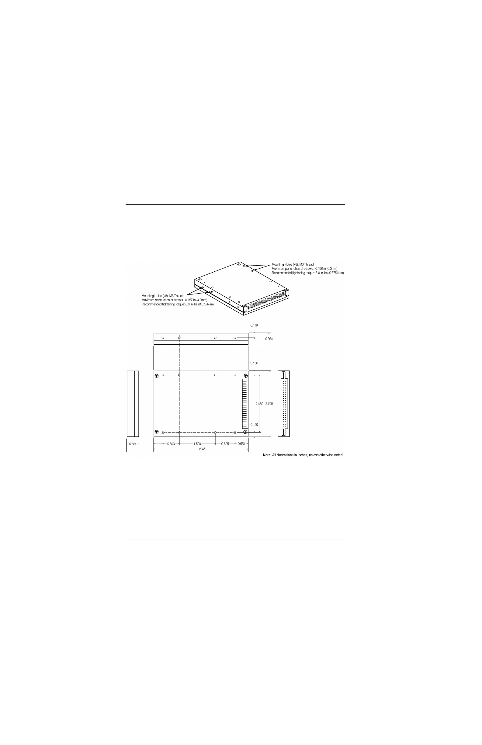
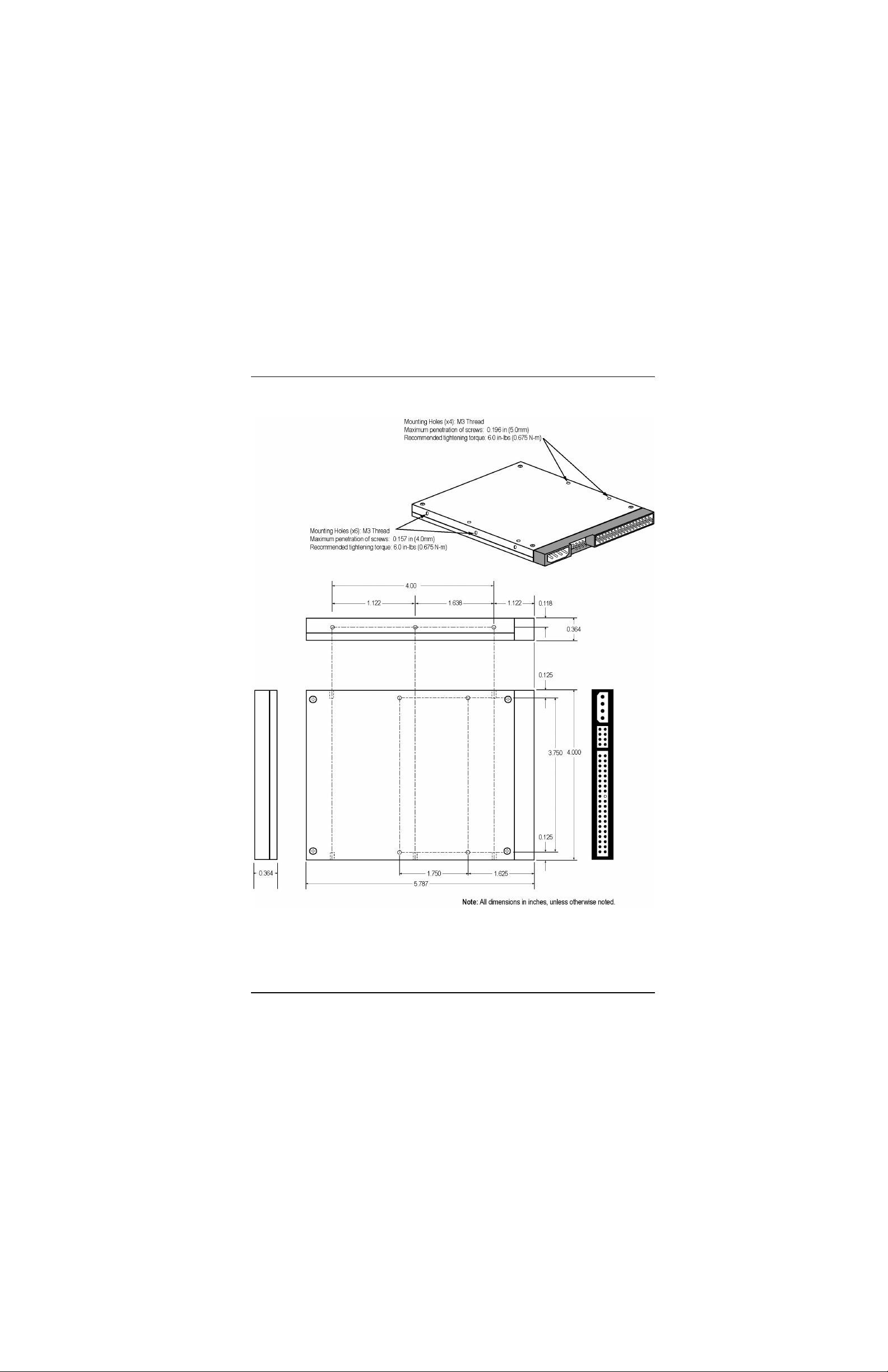
Zeus SSD internal components are housed in precision machined aluminum alloy
enclosures. The outside dimensions of 2.5-inch and 3.5-inch form factor drives are
provided in Table1. The 2.5-inch drive assembly is illustrated in Figure1 on page6. The
3.5-inch drive assembly is illustrated in Figure2 on page7.
Table 1. 2.5 and 3.5-inch Drive Assembly Dimensions
2.5-inch SSD 3.5-inch SSD
Thickness 0.0374 in (9.5 mm) 0.0374 in (9.5 mm)
Width 2.75 in (69.8 mm) 4.00 in (101.60 mm)
Length (maximum) 3.94 in (100.2 mm) 5.79 in (147 mm)
Zeus Ultra DMA Solid State Drives 5
Page 12
Product Description Physical Characteristics
Figure 1. 2.5-inch Zeus SSD Assembly Drawing
6 Zeus Ultra DMA Solid State Drives
Page 13
Physical Characteristics Product Description
Figure 2. 3.5-inch Zeus SSD Assembly Drawing
Zeus Ultra DMA Solid State Drives 7
Page 14

Product Description Environmental Characteristics
1.4.2 Drive Assembly Weight
The weight of a Zeus SSD varies, depending on the specific set of design characteristics
of the drive. A standard 32GB, 2.5-inch Zeus SSD weighs approximately 0.322 lb
(0.120Kg). A 72 GB SSD weighs 0.670 lb (0.250Kg). The following characteristics must
be taken into consideration in order to determine the exact weight of a drive.
• Storage capacity
• IC stacking technology (if used)
• Flash controller/memory configuration
• Form factor
1.5 ENVIRONMENTAL CHARACTERISTICS
To validate the SSD’s portability and suitability for operation in harsh mobile
environments, Zeus SSDs are subjected to a series of environmental tests.
1.5.1 Temperature, Humidity and Altitude
Zeus SSDs (all models) operate without degradation within the ambient temperature,
relative humidity and altitude ranges specified in Table2.
Table 2. Environmental Conditions
Operating Temperature
Commercial: 0° to 70° C (32° to 158° F)
Industrial: -40° to 85° C (-40° to 185° F)
Storage: -55° to 95° C (-67° to 203° F)
Relative Humidity
Altitude
8 Zeus Ultra DMA Solid State Drives
5 - 95%, non-condensing
80,000 ft.
Page 15

Electrical Characteristics Product Description
1.5.2 Shock and Vibration
In setting the initial baseline for shock and vibration test levels, the Zeus SSD was
exposed to increasingly harsh levels of stress until the drive’s failure levels were
determined. The tests were then repeated using the stress levels thereby established, to
verify that the SSD would meet these specifications consistently. This process
established the shock and vibration levels that have been used in subsequent shock and
vibration testing.
1.5.2.1 Mechanical Shock
Zeus SSDs are shock-tested in accordance with MIL-STD-810F and operate as
specified, without degradation, when subjected to the following:
Test Condition: Three 50G shocks (peak value, 11 ms duration, half-sine
waveform) along the x, y and z axes.
Test Result: 1,500G operating shock
1.5.2.2 Random Vibration
SimpleTech Zeus SSDs are vibration-tested in accordance with MIL-STD-810F and
operate as specified, without degradation, when subjected to the following:
Test Condition: Random vibration, between 20Hz and 2,000Hz along the x,
y and z axes.
Test Result: 16.3G operating vibration
1.6 ELECTRICAL CHARACTERISTICS
1.6.1 Operating Voltage
Zeus SSDs require an input voltage of +5.0 Vdc + 5% (4.75 - 5.25 Vdc).
Zeus Ultra DMA Solid State Drives 9
Page 16

Product Description Operation and Performance Characteristics
1.6.2 Power Consumption
The amount of power consumed by Zeus SSDs is determined by the storage (memory)
capacity of the drive, and the flash controller/memory configuration of the drive. Table3
lists (by capacity) the power consumption of Zeus SSDs during typical operations at 5
Vdc.
Table 3. Zeus SSD Typical Power Consumption (watts/mA)
Sustained Read/
Write
Sanitized Erase/Fill
(running low power option)
a. 10-40 MB/sec
b. 10-60 MB/sec
c. Estimated value
a
8 GB
2.50 watts/
431mA
3.00 watts/
600mA
a
16 GB
2.15 watts/
431mA
2.92 watts/
583mA
a
24 GB
2.15 watts/
431mA
3.38 watts/
675mA
32 G
2.15 watts/
502mA
3.71 watts/
741mA
1.7 OPERATION AND PERFORMANCE
CHARACTERISTICS
1.7.1 ATA (IDE) Bus Modes
Zeus SSDs support the following ATA operating modes:
• PIO Modes 0 through 4
• Ultra DMA Modes 0 through 4
1.7.2 Mount Time
a
b
72 GB
3.63 watts/
c
726mA
7.43 watts/
1485mA
c
The amount of time required to initialize and mount a Zeus SSD varies, depending on the
operating system (Windows®, Linux®, etc.) in which the SSD is running and the storage
capacity of the drive.
1.7.3 Seek Time
Unlike a magnetic rotating disk, the Zeus SSD has no moving head or platter. There is
no seek time or rotational latency issues to contend with. Zeus SSDs dramatically
improve transaction throughput, particularly for applications that are configured to take
advantage of the characteristics of the drive.
10 Zeus Ultra DMA Solid State Drives
Page 17

Operation and Performance Characteristics Product Description
1.7.4 Data Transfer Rate
The data transfer rate of Zeus SSDs depends on the flash controller/flash memory
configuration of the drive. The drive’s scalable architecture is capable of accommodating
sustained and burst data transfer rates as follows:
Sustained Read/Write Rates: 20, 30, 40 and 60 MB/sec
Burst Read/Write Rate: 66 MB/sec
1.7.5 Endurance
The useful life of a flash media is limited by the number of write/erase operations that can
be performed on the media. Typically, the write/erase cycles for flash media ranges
between 100,000 and 300,000. To extend the useful life of Zeus SSDs, special wearleveling and bad-block mapping algorithms are integrated in the drive’s firmware—
increasing the drive’s overall endurance rating to 2,000,000 write/erase cycles.
1.7.5.1 Wear-Leveling
The dynamic wear-leveling algorithm integrated in the Zeus SSD’s firmware guarantees
that erase/write cycles are evenly distributed across all of the drive’s flash memory block
locations. Wear-leveling eliminates repeated writes to the same physical flash memory
location, thereby preventing blocks from wearing out prematurely.
1.7.5.2 Bad-block Management
The Zeus SSD’s bad-block mapping algorithm, replaces bad blocks with new ones from
available spares. Onepercent (1%) of the Zeus SSD’s flash memory is held in reserve
(spare block) for bad block replacement. Bad blocks in the media are flagged when
detected. The next time an attempt is made to access a flagged block, it is immediately
replaced by a spare block. The drive’s bad block mapping function enables data to be
automatically transferred from a bad sector to an available spare block.
1.7.5.3 Data Retention
Data stored on Zeus SSDs remains valid for 10 years without requiring power support.
1.7.6 Reliability
1.7.6.1 Mean Time Between Failure (MTBF)
The average time Zeus SSDs work without failure is typically greater than 2,300,000
hours.
Zeus Ultra DMA Solid State Drives 11
Page 18

Product Description Operation and Performance Characteristics
1.7.6.2 Error Detection and Correction
The SSD’s error detection code and error correcting code (EDC/ECC) helps maintain
data integrity by allowing single or multiple bit corrections to the data stored in the drive’s
flash array. If the data in the flash array is corrupted due to aging or during the
programming process, EDC/ECC will compensate for the errors to ensure the delivery of
accurate data to the host computer. The EDC/ECC engine on the Zeus SSD is capable
of correcting up to two bytes in error and detecting up to 3 bytes in error. An extensive
retry algorithm is also implemented on all Zeus SSDs, so that single event disturbances
such as ESD or EMF occurring during a read operation can be readily overcome.
1.7.6.3 Built-in Self Test
During power-up, the SSD’s micro controller tests Zeus controller memory, and then
performs a back-end status check to verify proper flash memory controller operations. If
a fault condition is detected in the flash memory controller, the SSD’s status is reported
as failed.
12 Zeus Ultra DMA Solid State Drives
Page 19

Zeus SSD Functional Blocks Functional Description
2 FUNCTIONAL DESCRIPTION
2.1 ZEUS SSD FUNCTIONAL BLOCKS
SimpleTech™ Zeus series solid state drives comprise the following primary functional
component blocks:
• ATA (IDE) Bus Interface
• SSD Control
• Flash Memory
2.1.1 ATA (IDE) Bus Interface Block
This section provides information on the ATA (IDE) Bus interface connectors used with
2.5-inch and 3.5-inch Zeus SSD.
SimpleTech Zeus SSDs have a plastic key to block pin 20 on the ATA bus
(IDE) interface connector. Blocking pin20 prevents possible damage to
the SSD by making it impossible to connect to the drive improperly.
2.1.1.1 44-pin ATA Bus Connector
The 2.5-inch Zeus-series SSDs are equipped with a 44-pin ATA bus connector
(Figure3), located on the rear of the drive. DC power and IDE bus traffic is supplied
through a non-shielded 44-conductor I/O cable.
ATA standards require 80-conductor cables to be used for UltraDMA
modes 3 through 5. The length of the cable shall not exceed 18 inches.
Figure 3. 44-pin ATA (IDE) Bus Connector
Zeus Ultra DMA Solid State Drives 13
Page 20

Functional Description Zeus SSD Functional Blocks
2.1.1.2 3.5-inch SSD ATA Interface and Power Connectors
The 3.5-inch Zeus-series SSDs are equipped with a 40-pin, DC power/ATA bus
combination connector (Figure4), located at the rear of the drive. IDE bus traffic is
supplied through a non-shielded 40-conductor I/O cable. DC power is supplied through
a separate 4-conductor power cable.
ATA standards require 80-conductor cables to be used for UltraDMA
modes 3 through 5. The length of the cable shall not exceed 18 inches.
Figure 4. 40-pin ATA (IDE) Bus/DC Power Combination Connector
2.1.1.3 IDE Interface Connector Pinout Configuration
Table4 provides the signal assignment for each pin (electronic contact) on the ATA (IDE)
bus connectors used on Zeus SSDs. Except as noted, the table applies to both the 44pin ATA bus connectors (Figure3 on page13) on used 2.5-inch drives, and the 40-pin
ATA bus/DCpower combination connectors (Figure 4 above) used on 3.5-inch drives.
Table 4. ATA (IDE) Connector Pinout Configuration
Pin Pin Type Signal Symbol Signal Name Signal Description
1 I -RESET HOST RESET Reset signal from the host. Reset is active
on power up and inactive thereafter.
2 Ground GND — Ground
Continued
14 Zeus Ultra DMA Solid State Drives
Page 21

Zeus SSD Functional Blocks Functional Description
Table 4. ATA (IDE) Connector Pinout Configuration (Continued)
Pin Pin Type Signal Symbol Signal Name Signal Description
3 I/O D07 HOST DATA 7 Pins 3 through 18 (16 lines (15-0)) carry the
4 I/O D08 HOST DATA 8
5 I/O D06 HOST DATA 6
6 I/O D09 HOST DATA 9
data between the controller and the host.
The low 8 lines transfer commands and the
ECC information between the host and the
controller.
7 I/O D05 HOST DATA 5
8 I/O D10 HOST DATA 10
9 I/O D04 HOST DATA 4
10 I/O D11 HOST DATA 11
11 I/O D03 HOST DATA 03
12 I/O D12 HOST DATA 12
13 I/O D02 HOST DATA 02
14 I/O D13 HOST DATA 13
15 I/O D01 HOST DATA 01
16 I/O D14 HOST DATA 14
17 I/O D00 HOST DATA 0
18 I/O D15 HOST DATA 15
19 Ground GND — Ground
20 — — — No connection. Reserved for connector key.
21 O DREQ DMA REQUEST Not used
22 Ground GND — Ground
23 I -IOWR I/O WRITE This I/O Write strobe pulse is used to clock
I/O data or commands on the drive data bus
into the Drive controller registers when the
drive is configured to use the I/O interface.
The clocking will occur on the negative to
positive edge of the signal (trailing edge).
24 Ground GND — Ground
25 I -IORD I/O READ This is a Read strobe generated by the host.
The signal gates I/O data or status on the
host bus and strobes the data from the
controller into the host on the low to high
transition (trailing edge).
26 Ground GND — Ground
Continued
Zeus Ultra DMA Solid State Drives 15
Page 22

Functional Description Zeus SSD Functional Blocks
Table 4. ATA (IDE) Connector Pinout Configuration (Continued)
Pin Pin Type Signal Symbol Signal Name Signal Description
27 I IORDY I/O READY Not used, and pulled up to Vcc through a
4.7k ohm resistor.
28 I -CSEL CABLE SELECT This internally pulled up signal is used to
configure the drives as the Master or the
Slave device. When the pin is grounded, the
device is configured as a Master. When the
pin is open, the device is configured as a
Slave.
29 I -DACK DMA ACKNOWLEDGE Not used
30 Ground GND — Ground
31 O INTRQ INTERRUPT REQUEST This is an interrupt request from the
controller to the host, asking for service.
This signal is the active high Interrupt
Request to the host.
32 O -IOS16 I/O SELECT 16 Not used
33 I A1 HOST ADDRESS 1 This address line (A1) is used to select one
of eight registers in the controller Task File.
34 I/O -PDIAG After an Executive diagnostic command to
indicate to the Master it has passed its
diagnostics, this bi-directional open drain
signal is asserted by the Slave.
35 I A0 HOST ADDRESS 0 These address lines (A0 and A2) are used to
36 I A2 HOST ADDRESS 2
37 I -CS1 HOST CHIP SELECT 1 The chip select signal used to select the
38 I -CS2 HOST CHIP SELECT 2 The chip select signal used to select the
39 I/O -DASP DISK ACTIVE/SLAVE
PRESENT
40 Ground GND — Ground
41* — V
42* — V
CC
CC
Supply Voltage 5V power supply
Supply Voltage 5V power supply
43* Ground GND — Ground
44* — — — No connection
* Applies to 44-pin, 2.5-inch SSD only
select one of eight registers in the controller
Task File.
Task File register.
Alternate Status register and the Device
Control register.
This input/output is the Disk Active/Slave
Present signal in the Master/Slave
handshake protocol.
16 Zeus Ultra DMA Solid State Drives
Page 23

Zeus SSD Functional Blocks Functional Description
2.1.2 SSD Control Block
The Zeus SSD’s control block comprises three integrated components:
• SimpleTech Zeus SSD controller
• RISC Microcontroller
• NAND SLC flash memory
SimpleTech’s Zeus FPGA (Field Programmable Gate Array) controller is the heart of the
Zeus SSD. The Zeus controller provides the drive’s ATA interface to the host, and the
IDE interface to the drive’s local flash memory. The Zeus controller’s integrated DMA
controller interfaces with system memory to facilitate data transfer between the host and
the SSD’s local flash memory.
An integrated microcontroller is responsible for initiating and controlling all activity within
the Zeus ATA controller. The microcontroller features more than 1Mbit of on-chip SRAM
and a wide range of peripheral functions, with 8Mbits of flash memory into a single
compact 120-ball BGA package, providing a powerful and flexible solution for the SSD’s
embedded control applications. The SSD’s embedded microcontroller is a highperformance processor with a high-density instruction set and very low power
consumption. In addition, a large number of internally banked registers provide very fast
exception handling—making it ideal for the real-time application control requirements of
the SSD. The 8-level priority-vectored interrupt controller, together with the Peripheral
Data Controller, significantly enhance the SSD’s real-time performance.
The SSD’s flash memory controller architecture requires only minimal external
component support. The SSD’s flash controller works with flash memory devices from
Samsung® and Toshiba®, as well as a number of compatible flash memory devices from
other manufacturers.
Features of the drive’s flash memory controller include:
• Built-in 3.3V voltage regulator for flash memory supply
• Data transfer rates up to 60 MB/sec (controller to flash memory)
• True-IDE mode support
• Embedded ECC unit
• Wear-leveling and bad-block mapping software
Zeus Ultra DMA Solid State Drives 17
Page 24

Functional Description Zeus SSD Functional Blocks
2.1.3 Flash Memory
The Zeus SSD’s local storage subsystem uses Single-Level Cell (SLC) NAND, nonvolatile flash memory. Having only two states and one bit of data stored, SLC NAND flash
control logic on the SSD is able to conserve energy when managing the electrical charge
during operations.
2.1.3.1 Storage Capacity
Table5 on page18, provides a representative list of the various capacities in which
SimpleTech’s Zeus SSDs are available, along with associated LBA (Logical Bit
Addressing) and CHS (Cylinder, Head, Sector) information.
Table 5. Zeus SSD Capacity
Logical Bit Addressing (LBA) Data Cylinder, Head, Sector (CHS) Data
Capacity (GB)
(unformatted)
8 16090112 16089696 15962 16 63
16 32196608 16514064 16383 16 63
24 48302080 16514064 16383 16 63
32 64408576 16514064 16383 16 63
72 144919296 16514064 16383 16 63
a. Expressed as LBA sectors
User-Addressable
LBA Sectors
CHS
Capacity
a
Logical
Cylinders
Logical
Heads
Logical
Sectors
18 Zeus Ultra DMA Solid State Drives
Page 25

Principles of Operation Functional Description
2.2 PRINCIPLES OF OPERATION
The Zeus SSD comprises three primary functional blocks—the ATA (IDE) interface
connector, Zeus SSD controller and NAND flash memory. A description of each drive
component is provided in “Zeus SSD Functional Blocks” on page13.
All read/write data transfer requests are initiated by the host via the ATA (IDE) bus
interface. Once received, the Zeus controller, under the control of the SSD’s
microcontroller, processes the request.
The SSD’s microcontroller is responsible for initiating and controlling
all activity within the Zeus controller—including bad block mapping and
executing the wear-leveling algorithms.
The Zeus controller decodes an incoming host command, and sets up
the appropriate interrupts and status for the local microprocessor to
handle various ATA commands. For read and write transfer commands,
the hardware can handle the initial handshake with the host
automatically. If firmware enables full auto mode, read and write
transfers can be fully handled by hardware with minimum firmware
support.
Commands that do not require data to be read from or written to the flash memory
controller are typically handled by the Zeus controller. Some commands may require the
Zeus controller to use external circuitry (for example, Intelligent Destructive Purge™),
which do not involve the flash memory controller.
When a write operation is requested and data is received, the Zeus controller uses
integrated DMA controllers to transfer the data from host memory to the SSD’s flash
memory controller. Through a standard ATA (IDE) interface, the flash memory controller
transfers the data from the Zeus controller to available locations in the SSD’s local flash
memory. Depending on drive configuration, Zeus SSD storage capacity can range
between from 2GB to 128GB, with internal IDE transfer rates ranging from 10 to 60 MB
per second. After the write operation completes, the Zeus controller notifies the host.
If a read request is received, the Zeus controller retrieves the data from the local flash
memory via the flash memory controller. If the Zeus controller is responding to a PIO read
operation, it presents the data to the ATA bus. If it is responding to a UDMA read request,
the Zeus controller writes the data directly to system memory on the host. Regardless of
the type of operation (PIO or UDMA), the Zeus controller notifies the host when the data
is ready for transmission.
Zeus Ultra DMA Solid State Drives 19
Page 26

Functional Description Operating Modes
2.3 OPERATING MODES
The Zeus SSD is configured as a high-performance I/O device, supporting the following
operating modes:
• Primary drive address at system ATA I/O address 1F0h - 1F7h and 3F6h - 3F7h. The
host must provide chip-enable #CS0 and #CS1. The SSD decodes addresses DA0
- DA2.
• Secondary drive address at system ATA I/O address 170h - 177h and 376h - 377h.
The host must provide chip-enable #CS0 and #CS1. The SSD decodes addresses
DA0 - DA2.
2.3.1 I/O Primary and Secondary ATA (IDE) Modes
Primary and secondary drive addressing modes allow hosts to use the ATA-standard’s
reserved disk drive I/O addresses. This provides computer system designers with the
simplest way to accommodate ATA-protocol devices.
2.3.1.1 Addressing Modes
Zeus SSDs, on a command by command basis, can operate in either CHS or LBA
addressing modes. Identify Drive Information (see “Identify Drive Information” on
page23) tells the host whether the drive supports LBA mode. The host selects LBA
mode via the Drive/Head register. Sector Number, Cylinder Low, Cylinder High, and
Drive/Head register bits HS3=0 contain the zero-based LBA. The drive's sectors are
linearly mapped with: LBA = 0 => Cylinder 0, head 0, sector 1. Regardless of the
translation mode, a sector LBA address does not change. LBA = (Cylinder * no of heads
+ Head) * (sectors/track) + (Sector - 1). Table6 on page21 lists the supported IDE
addressing modes.
20 Zeus Ultra DMA Solid State Drives
Page 27

ATA Commands Functional Description
Table 6. ATA (IDE) Bus Addressing Modes
#CS0 #CS1 DA2 DA1 DA0 #IORD = “0” #IOWR - “0”
1 1 X X X Hi-Z Not Used
1 0 0 X X Hi-Z Not Used
1 0 1 0 X Hi-Z Not Used
0 0 X X X Invalid Invalid
1 0 1 1 0 Alternate status Device Control
1 0 1 1 1 Device address Not Used
0 1 0 0 0 Data Data
0 1 0 0 1 Error Feature
0 1 0 1 0 Sector Count Sector Count
0 1 0 1 1 Sector Number Sector Number
0 1 1 0 0 Cylinder Low Cylinder Low
0 1 1 0 1 Cylinder High Cylinder High
0 1 1 1 0 Drive/Head Drive/Head
0 1 1 1 1 Status Command
2.4 ATA COMMANDS
This section provides information on the ATA commands supported on the Zeus SSD.
The commands are issued to the ATA by loading the required registers in the command
block with the supplied parameter, and then writing the command code to the register.
2.4.1 ATA Command Flow
1 Write the necessary parameter to the related Task File registers and by writing the
command in the Command register, the command is issued.
2 Upon the receipt of the command, the device sets the BSY bit within 400 n/sec.
3 If a data transfer command (e.g., Read command, Write command) was called, the
DRQ bit in the Status register will come up, indication that the transfer can begin.
Zeus Ultra DMA Solid State Drives 21
Page 28

Functional Description ATA Commands
2.4.2 Standard ATA Commands
Table7 lists each command along with its respective command code and registers
accessed by the command. For detailed descriptions of the ATA commands, refer to the
ATA-5 specification.
Table 7. Supported ATA Commands
Command
Command
Code (Hex)
Feature
Register
Sector
Count
Register
Sector
Number
Register
Cylinder
High/Low
Register
CHECK POWER MODE 98 or E5 No Yes No No
ERASE SECTOR C0 No Yes Yes Yes
EXECUTE DRIVE
90 No No No No
DIAGNOSTIC
FORMAT TRACK 50 No Yes No Yes
IDENTIFY DRIVE EC Yes No No No
IDLE 97, E3 No Y No No
IDLE IMMEDIATE 95, E1 No No No No
INITIALIZE DRIVE
91 No Yes No No
PARAMETERS
READ MULTIPLE C4 No Yes Yes Yes
READ SECTOR(S) 20 No Yes Yes Yes
READ VERIFY SECTOR(S) 40 No Yes Yes Yes
RECALIBRATE 10 No No No No
SEEK 70 - 7F No No Yes Yes
SET FEATURES EF No Yes Yes Yes
SET MULTIPLE MODE C6 No Yes No No
SET SLEEP MODE 99 or E6 No No No No
STANDBY 96 or E2 No Yes No No
STANDBY IMMEDIATE 94 or E0 No No No No
WRITE MULTIPLE C5 No Yes Yes Yes
WRITE SECTOR(S) 30 No Yes Yes Yes
a. Only drive parameters are valid.
b. Drive and head parameters are valid.
c. Address to drive 0 (zero). When executed, Both drives (master and slave) execute this command).
Drive/Head
Number
Register
a
Yes
b
Yes
c
Yes
(b)
Yes
(a)
Yes
(a)
Yes
(a)
Yes
(b)
Yes
(b)
Yes
(b)
Yes
(b)
Yes
(a)
Yes
(b)
Yes
(b)
Yes
(a)
Yes
(a)
Yes
(a)
Yes
(a)
Yes
(b)
Yes
(b)
Yes
22 Zeus Ultra DMA Solid State Drives
Page 29

ATA Commands Functional Description
2.4.3 Optional ATA Command Support
2.4.3.1 SMART (Self-Monitoring, Analysis and Reporting
Technology)
Zeus SSDs are designed to operate in mission-critical systems where remote monitoring
of the drives’s internal status is required, but removal of the drive for status checking is
unacceptable. To provide remote monitoring support, Zeus SSDs can be programmed
with the optional SMART feature. SMART enables the SSD to perform internal system
monitoring, and report on the status of the drive. SMART is also used to analyze the
SSD’s bad-block status. The total number of bad blocks accumulated from the date of
manufacture; relative to the disk total capacity, is returned as status information.
Monitoring accumulated bad blocks over time provides an indication of drive reliability
and the expected life span of the drive in the system in which the it is installed.
2.4.3.2 Identify Drive Information
The Identify Drive command enables the host to receive parameter information from the
SSD. When the Identify Drive command executes, the SSD sets the BSY bit, prepares
to transfer the 256 words of SSD identification data to the host, sets the DRQ bit, clears
the BSY bit, and then generates an interrupt. The host can then transfer the data by
reading the Data register. All reserved bits or words are all zero. Table8 contains typical
Identify Drive Information for the Zeus SSD.
Table 8. SSD Identify Drive Information
(a)
(a)
(a)
(a)
(a)
(a)
Total
Bytes
a
2 Default number of cylinders
2 Default number of heads
2 Number of unformatted bytes per track (not used)
2 Number of unformatted bytes per sector (not used)
2 Default number of sectors per track
4 Number of sectors per drive (Word7 = MSW, Word8 = LSW)
20 Serial number
Description
continued
Word Data
0 8040h 2 General configuration bit-significant information (value fixed by CFA)
1
2 0000h 2 Reserved
3
4
5
6
7-8
9 0000h 2 Reserved
10-19
Zeus Ultra DMA Solid State Drives 23
XXXXh
XXXXh
XXXXh
XXXXh
XXXXh
XXXXh
XXXXh
Page 30

Functional Description ATA Commands
Table 8. SSD Identify Drive Information (Continued)
(a)
(a)
(a)
(a)
Total
Bytes
Description
2 Buffer type (dual ported, multi-sector, with read cache)
2 Buffer size (in 512 byte increments)
2 Number of ECC bytes passed on Read/Write Long Sector commands
48 Firmware version and model number in ASCII
Word Data
20
21
22
23-46
XXXXh
XXXXh
XXXXh
XXXXh
47 8001h 2 Maximum sector count = 1 on Read/Write Multiple commands
48 0000h 2 Double word not supported
49 2F00h 2 Capabilities: DMA not supported (bit 8); LBA supported (bit 9)
50 0000h 2 Reserved
51 0200h 2 PIO data transfer cycle timing mode
52 0200h 2 Single word DMA data transfer cycle timing mode (not supported)
53 0007h 2 Words 54 - 58 and 64 - 70 are valid
54
55
56
57
58
XXXXh
XXXXh
XXXXh
XXXXh
XXXXh
(a)
(a)
(a)
(a)
(a)
2 Number of current cylinders
2 Number of current heads
2 Number of current sectors per track
2 LSW of the current capacity in sectors
2 MSW of the current capacity in sectors
59 0000h 2 Current setting for block count = 1 for Read/Write Multiple commands
60-61
XXXXh
(a)
4 Total number of user addressable sectors in LBA Mode
62 0000h 2 Single word DMA data transfer cycle timing mode not supported
63 0000h 2 Multi-word DMA modes active; modes 0 - 2 supported
64 0003h 2 Advanced PIO modes supported (modes 3 and 4)
65 0078h 2 Minimum multi-word DMA transfer cycle time per word (ns)
66 0078h 2 Recommended multi-word DMA transfer cycle time per word (ns)
67 00F0h 2 Minimum PIO transfer without flow control
68 0078h 2 Minimum PIO transfer with IORDY flow control
69-255 0000h 388 Reserved
a. Value varies depending on drive storage capacity.
24 Zeus Ultra DMA Solid State Drives
Page 31

ATA Commands Functional Description
2.4.4 Vendor-Specific ATA Commands
As with standard ATA command, the software requirements and syntax of the vendorspecific ATA commands the host issues to the Zeus SSD are issued to the ATA by
loading the required registers in the command block with the supplied parameters, and
then writing the command code to the register.
For additional information on proprietary SimpleTech ATA commands, contact your
SimpleTech representative. Contact information is provided in “Contact and Ordering
Information” on page31.
2.4.4.1 Sanitize Erase/Fill
Zeus SSDs offer optional destructive and non-destructive sanitization (purge) features.
Non-destructive security erase removes the drive’s data, then overwrites (fills) each
addressable block of memory with a predetermined pattern, as specified by the
sanitization specification, such as DoD 5220.22M, to which the SSD complies.The
destructive security erase feature removes the drive’s data, and then destroys the flash
media—making the SSD totally unusable and data retrieval impossible. SimpleTech’s
non-destructive and patent-pending destructive security erase algorithms monitor and
confirm completion of the sanitization process.
Both security erase features support Low Power and Fast Erase options. The Low Power
option accesses each addressable memory block sequentially to conserve power. The
Fast Erase option accesses all addressable blocks simultaneously, forgoing power
conservation for speed.
Zeus Ultra DMA Solid State Drives 25
Page 32

Functional Description ATA Commands
2.4.4.2 Sanitization Standards
Zeus SSDs comply with the sanitization requirements described in Table9.
Table 9. Sanitize Standards Compliance
Specification Document Description/Comment
USA DoD 5220.22-M
National Industrial Security Program
Operation Manual (NISOM)
January 1995
NSA 130-2
Media Declassification and Destruction
Manual
November 2000
AR 380-19
Information Systems Security (ISS)
27 March 1998
AFSSI 5020
USA Air Force System Security
Instruction (AFSSI) 5020
20 August 1996
Navso P-5239-26
Information Systems Security (INFOSEC)
Program Guidelines
Specifies the sanitization process for various media types in
order to be considered declassified.
Specifies the sanitization procedure for semiconductor memory
devices.
Provides the security requirements for systems processing
Special Access Program (SAP) information and describes the
ISS policy as it applies to security in hardware, software
procedures, telecommunication, personal use, physical
environment, networks and firmware.
Section VII, Automated Information System Media, Section 2-20,
describes cleaning, purging, declassifying and destroying media.
Appendix F-2 describes how to sanitize flash memory.
Specifies the sanitization procedure for confidential media.
Chapter 5, Semiconductor Devices, describes the security
procedure for all types of semiconductor media. Paragraph 5.3
describes the procedure for sanitizing flash memory.
Provides policy, guidelines, and procedures for clearing and
purging computer system memory and other storage media for
release outside of and for reuse within controlled environments.
It pertains to both classified and sensitive unclassified
information. Implements DOD 5200.28-M and CSC-STD-005-85.
Chapter 3 describes the cleaning and purging of data storage
media.
26 Zeus Ultra DMA Solid State Drives
Page 33

System Requirements Installation
3 INSTALLATION
3.1 SYSTEM REQUIREMENTS
Before installing the Zeus SSD in your system, make sure you have the following items:
• Mounting hardware (as required)
• ATA (IDE) bus interface cable (as specified in Table10, below)
• For 3.5-inch Zeus SSD; available 5V power source (4-pin connector)
Table 10. ATA (IDE) Cable Requirements
Drive (form factor) ATA (IDE) Interface Operating Mode
2.5-inch Zeus SSD 44-pin; 44 conductor PIO modes 0, 1, 2, 3 and 4
44-pin 80-conductor Ultra DMA modes 3 and 4
3.5-inch Zeus SSD 40-pin; 40 conductor PIO modes 0, 1, 2, 3 and 4
40-pin; 80 conductor Ultra DMA modes 3 and 4
3.2 DRIVE CONFIGURATION
Before installing the SSD, the drive must be configured to operate as either the Master
or Slave IDE device. The Master/Slave setting represents the ordering of electronic
devices on an IDE channel. If the Zeus SSD is the only ATA (IDE) drive installed in the
system, set up the drive as the master device. If two drives are installed in the machine,
one device must be configured as the master and the other as the slave. Jumpers located
at the rear of the Zeus SSD allow you to configure the drive as either the Master or the
Slave device.
Ultra DMA modes 0, 1 and 2
Ultra DMA modes 0, 1 and 2
Zeus Ultra DMA Solid State Drives 27
Page 34

Installation Drive Configuration
3.2.1 Configuring 2.5-inch Form Factor Zeus SSD
Zeus SSDs conforming to the 2.5-inch form factor, use a 44-pin ATA bus connector. To
configure the SSD as either the Master or Slave device, place a jumper across the
appropriate pins (A-D) as illustrated in Figure5 on page28.
In systems with multiple drives, it may be necessary to configure disk
storage in a Master/Slave configuration. To accomplish this, boot the
computer using IDE HDD Auto Detection available in the CMOS setup.
Figure 5. Master/Slave Setting for 2.5-inch Zeus SSDs
28 Zeus Ultra DMA Solid State Drives
Page 35

Drive Configuration Installation
3.2.2 Configuring 3.5-inch Form Factor Zeus SSD
Zeus SSDs conforming to the 3.5-inch form factor, use a 40-pin ATA bus/DC power
combination connector. To configure the SSD as either the Master or Slave device, place
a jumper across the appropriate pins (1-8) as illustrated in Figure6 on page29.
In systems with multiple drives, it may be necessary to configure disk
storage in a Master/Slave configuration. To accomplish this, boot the
computer using IDE HDD Auto Detection available in the CMOS setup.
Figure 6. Master/Slave Setting for 3.5-inch Zeus SSDs
Zeus Ultra DMA Solid State Drives 29
Page 36

Installation Installing Zeus SSDs
3.3 INSTALLING ZEUS SSDS
To install the Zeus SSD in a personal computer (PC) or host system, complete the
following steps:
1 Power down the computer and remove the access cover.
2 Configure the Zeus SSD as the master or slave device in accordance with the
information provided in “Drive Configuration” on page27.
3 Connect one end of an ATA (IDE) cable to the Zeus SSD and the other end of the
cable to the IDE adapter on the host. Orient the cable so that pin 1 on the Zeus SSD
connects to pin 1 on the host adapter.
ATA standards require 80-conductor cables to be used for UltraDMA
modes 3 through 5. The length of the cable shall not exceed 18 inches.
4 If installing a 3.5-inch SSD, connect a power cable from the computer’s power source
to the 4-pin power connector located on the rear of the SSD.
5 Position the Zeus SSD in an unused drive bay and secure it in place using six (6)
machine screws. Apply sufficient torque to ensure that the drive is secure.
6 Replace the access cover and power on the computer.
3.3.1 Formatting Zeus SSDs for Windows, Linux and Other OS
Environments
After installing the Zeus SSD (see section “Installing Zeus SSDs” on page30), it is ready
for use. Zeus SSDs do not require special driver installation, adjustments or
modifications.
Zeus SSDs are low-level formatted at the factory. However, the SSD
must be partitioned and high-level formatted.
3.4 UPGRADING ZEUS SSD FIRMWARE
The firmware on the Zeus SSD is field upgradeable.
30 Zeus Ultra DMA Solid State Drives
Page 37

Upgrading Zeus SSD Firmware Contact and Ordering Information
CONTACT AND ORDERING INFORMATION
CONTACTING SIMPLETECH
For more information on Zeus Ultra DMA Solid State Drives, contact the SimpleTech
Solid State Drive Team.
Phone: 800-796-4645 (Toll free; US and Canada only); (949) 260-8345
Fax: (949) 851-2756
Email: ssd@simpletech.com
ORDERING INFORMATION
How to read the SSD’s part number:
Part Number Description
Z x xx xx xxx x xx xxxx
(for example, Z2A2A16C4BA)
Customer identifier (optional; SimpleTech internal use)
Build information (optional; SimpleTech internal use)
Temperature Rating:
C = Commercial
I = Industrial
Storage Capacity:
2 = 2 GB
128 = 128 GB
Sustained Data Transfer Rate:
2A = 20 MB/s
3A = 30 MB/s
4A = 40 MB/s
6A = 60 MB/s
Interface:
A = ATA
S = Serial ATA (SATA)
Form Factor:
0 = Custom
2 = 2.5 inch
3 = 3.0 inch
Controller type:
Z = Zeus
Zeus Ultra DMA Solid State Drives 31
Page 38

Contact and Ordering Information Upgrading Zeus SSD Firmware
32 Zeus Ultra DMA Solid State Drives
Page 39

Acronyms and Abbreviations
ACRONYMS A ND ABBREVIATIONS
A
ARM (Advanced RISC Machine) <processor> (ARM,
Originally Acorn RISC Machine). A series of lowcost, power-efficient 32-bit RISC microprocessors for
embedded control, computing, digital signal
processing, games, consumer multimedia and
portable applications.
ATA (AT Attachment) The IDE interface is officially
known as the ATA specification. ATA-2 (Fast ATA)
defined the faster transfer rates used in Enhanced
IDE (EIDE). ATA-3 added interface improvements,
including the ability to report potential problems (see
S.M.A.R.T.). Starting with ATA-4, either the word
“Ultra” or the transfer rate was added to the name in
various combinations. For example, at 33 MBytes/
sec, terms such as Ultra ATA and ATA-33 have been
used. In addition, Ultra ATA-33, DMA-33 and Ultra
DMA-33 are also found.
C
CFA (Computer Fraud and Abuse Act of 1986) The
CFA was a significant step forward in criminalizing
unauthorized access to computer systems and
networks. The Act applies to “federal interest
computers” which include systems used by the U.S.
government, as well as most financial institutions.
The Act makes unauthorized penetration or other
damage to such systems a felony.
CHS Cylinder, Head, Sector A disc-drive system and
method for generating logical zones that each have
an approximate number of spare sectors, and that
are used to translate logical block addresses.
CISC (Complex Instruction Set Computer)
Pronounced “sisk.” The traditional architecture of a
computer which uses microcode to execute very
comprehensive instructions. Instructions may be
variable in length and use all addressing modes,
requiring complex circuitry to decode them.
D
DMA (Direct Memory Access) Specialized circuitry
or a dedicated microprocessor that transfers data
from memory to memory without using the CPU.
Although DMA may periodically steal cycles from the
CPU, data are transferred much faster than using the
CPU for every byte of transfer.
DoD (Department of Defense) The military branch of
the U.S. government, which is under the direction of
the Secretary of Defense, the primary defense policy
adviser to the President.
DSL (Digital Subscriber Line) A technology that
dramatically increases the digital capacity of ordinary
telephone lines (the local loops) into the home or
office. DSL speeds are tied to the distance between
the customer and the telco central office (CO). DSL
is geared to two types of usage. Asymmetric DSL
(ADSL) is for Internet access, where fast
downstream is required, but slow upstream is
acceptable. Symmetric DSL (SDSL, HDSL, etc.) is
designed for short haul connections that require high
speed in both directions.
DSLAM (DSL Access Multiplexer) A central office
(CO) device for ADSL service that combines voice
traffic and DSL traffic onto a customer's DSL line. It
also separates incoming phone and data signals and
directs them onto the appropriate carriers network.
E
EDC/ECC (Error Detection Code/Error Correction
Code) A memory system that tests for and corrects
errors automatically, very often without the operating
system being aware of it. When writing the data into
memory, ECC circuitry generates checksums from
the binary sequences in the bytes and stores them in
an additional seven bits of memory for 32-bit data
paths or eight bits for 64-bit paths. When data are
retrieved from memory, the checksum is recomputed
to determine if any data bits have been corrupted.
Such systems can typically detect and automatically
correct errors of one bit per word and can detect, but
not correct, errors greater than one bit.
Zeus Ultra DMA Solid State Drives 33
Page 40

Acronyms and Abbreviations
F
FPGA (Field Programmable Gate Array) A type of
gate array that is programmed in the field rather than
in a semiconductor fabrication facility. Containing up
to hundreds of thousands of gates, there are a
variety of FPGA architectures on the market. Some
are very sophisticated, including not only
programmable logic blocks, but programmable
interconnects and switches between the blocks. The
interconnects take up a lot of FPGA real estate,
resulting in a chip with very low gate density
compared to other technologies.
H
HDD (Hard Disk Drive) The primary computer
storage medium, made of one or more aluminum or
glass platters, coated with a ferromagnetic material.
Most hard disks are “fixed disks,” which have platters
that reside permanently in the drive.
I
I/O (Input/Output) Transferring data between the
CPU and a peripheral device. Every transfer is an
output from one device and an input into another.
IDE (Integrated Drive Electronics) A type of
hardware interface widely used to connect hard
disks, CD-ROMs and tape drives to a PC. IDE was
always the more economical interface, compared to
SCSI. Starting out with 40MB capacities years ago,
20GB IDE hard disks have become entry level,
costing a fraction of a cent per megabyte.
IO (Input/Output; see I/O)
L
LSW (Least Significant Word) “Word” denotes
sequence of 4 bytes, or 32 bits, with the left-most
being the least significant, and the right-most being
the most significant. “Double-word” denotes
sequence of two words, or 64bits, with the left most
word being the least significant, and the right-most the most significant. Note, that the definition of
“word” defines a little-endian scheme, so for bigendian platforms, or network applications, special
steps need to be taken to reorder the bytes form the
input stream.
M
MLC (Multi-Level Cell) A flash memory technology
that stores more than one bit of data per cell.
Traditional flash memory defines a 0 or 1 bit, based
on a single voltage threshold. The patterns of two bits
(0-0, 0-1, 1-0, and 1-1) can be achieved with four
voltage levels and eight levels of voltage can yield all
the combinations in three bits.
MSB (Most Significant) “byte” defines a sequence of
8-bits, with the right-most bit being the least
significant and the left-most bit being the mostsignificant.
MSW (Most Significant Word) “Word” denotes
sequence of 4 bytes, or 32 bits, with the left-most
being the least significant, and the right-most being
the most significant. “Double-word” denotes
sequence of two words, or 64bits, with the left most
word being the least significant, and the right-most the most significant. Note, that the definition of
“word” defines a little-endian scheme, so for bigendian platforms, or network applications, special
steps need to be taken to reorder the bytes form the
input stream.
LBA (Logical Block Addressing) A method used to
support IDE hard disks larger than 504MB
(528,482,304 bytes) on PCs. LBA provides the
necessary address conversion in the BIOS to
support drives up to 8GB. BIOS after mid-1994,
which are sometimes called “Enhanced BIOS,”
generally provide LBA conversion. LBA support is
required for compatibility with the FAT32 directory.
LSB (Least Significant Byte) “Byte” defines a
sequence of 8-bits, with the right-most bit being the
least significant and the left-most bit being the mostsignificant.
N
NAND (Not AND) A Boolean logic operation that is
true if any single input is false. Two-input NAND
gates are often used as the sole logic element on
gate array chips, because all Boolean operations can
be created from NAND gates.
P
PIO (Programmed Input/Output) The data transfer
mode used by IDE drives. PIO modes use the CPU’s
registers for data transfer in contrast with DMA,
which transfers directly between main memory and
the peripheral device.
34 Zeus Ultra DMA Solid State Drives
Page 41

R
RISC (Reduced Instruction Set Computer) A
computer architecture that reduces chip complexity
by using simpler instructions. RISC compilers have
to generate software routines to perform complex
instructions that were previously done in hardware
by CISC computers. In RISC, the microcode layer
and associated overhead is eliminated.
S
SLC Single-Level Cell A flash memory technology
that stores one bit of data per memory cell;
supporting only two states: erased (1) or
programmed (0).
SMART (Self-Monitoring Analysis and Reporting
Technology) An “early warning system” for
anticipating pending drive problems. The drive’s
integrated controller works with various sensors to
monitor several aspects of the drive's performance.
Using this status information, SMART determines if
the drive is behaving normally or not, and then
makes the information available to software that
probes the drive.
SSD (Solid State Disk) Disk drive that uses memory
chips instead of rotating platters for data storage.
Used in battery-powered handheld devices as well
as desktop computers and servers, solid state disks
(SSDs) are faster than regular disks because there is
zero latency (there is no read/write head to move).
They are also more rugged than hard disks and offer
greater protection in hostile environments.
T
Acronyms and Abbreviations
True-IDE Flash memory devices (such as CF cards)
have a pin that when connected to the proper voltage
at power-up selects the “True-IDE” mode of
operation instead of the “PC-CARD-ATA” mode of
operation. This is the mode used in the interface.
U
Ultra ATA An enhanced version of the IDE interface
that transfers data at 33, 66 or 100 Mbytes/sec.
These enhancements are also called “Ultra DMA,”
“UDMA,” “ATA-33,” “ATA-66,” “ATA-100,” “DMA-33,”
“DMA-66” and “DMA-100.”
Ultra DMA (see Ultra ATA)
Zeus Ultra DMA Solid State Drives 35
Page 42

Acronyms and Abbreviations
36 Zeus Ultra DMA Solid State Drives
Page 43

Index
INDEX
Numerics
40-pin, DC power/ATA bus combination connector 14
44-pin ATA Bus Connector 13
A
addressing modes 20
altitude, operating 8
ATA (IDE) bus interface connectors 13
ATA (IDE) bus modes 10
ATA commands
command codes list 22
flow 21
Identify Drive 23
ATA commands, supported 21
ATA/IDE interface 3
B
bad-block mapping, endurance
bad-block mapping 11
BITS (Built-In Self Test) 12
C
capacity, storage 18
certification and warranty 41
compatibility 2
compliance and conformity 2
configuring 2.5-in drives 28
configuring 3.5-in drives 29
connector, 40-pin, DC power/ATA bus combination
14
connector, 44-pin ATA bus 13
connector, ATA (IDE) bus interface 13
D
data retention 11
data transfer rate 11
description
40-pin, DC power/ATA bus combination
connector 14
44-pin ATA bus connector 13
ATA (IDE) bus interface connectors 13
functional blocks 13
product 1
description, functional 13
drive assembly 5, 6
drive configuration 27
E
Electrical Characteristics
operating voltage 9
electrical characteristics 9
power consumption 10
endurance 4, 11
data retention 11
wear-leveling 11
environmental characteristics 4, 8
shock 9
shock and vibration 9
temperature, humidity and altitude 8
vibration 9
error detection and correction 12
Export Administration Regulation ii
F
FCC compliance 41
FCC Declaration 41
Zeus Ultra DMA Solid State Drives 37
Page 44

Index
features 3
ATA/IDE interface 3
endurance 4
optional (proprietary) 4
performance 3
physical characteristics 4
reliability 3
SMART 23
firmware upgrades 30
flash memory 18
formatting the Zeus SSD 30
functional blocks 13
functional description 13
H
humidity, operating 8
I
I/O Primary and Secondary ATA (IDE) Modes 20
IDE connector pinout 14
Identify Drive command 23
installation
drive configuration 27
Master/Slave configuration 27
system requirements 27
installing the SSD 30
interface connector
40-pin, DC power/ATA bus 14
44-pin ATA bus 13
ATA (IDE) bus 13
M
Master/Slave configuration 27
2.5-inch drives 28
3.5-inch drives 29
mechanical shock 9
memory, flash 18
modes, addressing 20
mount time 10
MTBF (mean time between failure 11
N
NAND-based flash memory 18
O
operating modes 20
I/O Primary and Secondary ATA (IDE)
Modes 20
operating voltage 9
optional features 4
SMART 23
P
performance 3
performance characteristics 10
ATA (IDE) bus modes 10
bad-block mapping 11
built-in self test (BITS) 12
data retention 11
data transfer rate 11
endurance 11
error detection and correction 12
mean time between failure (MTBF) 11
mount time 10
reliability 11
seek time 10
wear-leveling 11
physical characteristics 5
drive assembly 5, 6
physical characteristics, features
physical characteristics 4
pinout, IDE connector 14
power consumption 10
principles of operation 19
product description 1
proprietary features 4
38 Zeus Ultra DMA Solid State Drives
Page 45

R
random vibration 9
reliability 3, 11
BITS (Built-In Self Test) 12
error detection and correction 12
MTBF (mean time between failure) 11
S
sanitization standards 26
seek time 10
shock and vibration 9
shock, mechanical 9
SLC flash memory 18
SMART 23
standard features 3
storage capacity 18
system requirements 27
T
temperature, operating 8
Index
U
upgrading firmware 30
V
vibration, random 9
voltage, operating 9
W
warranty 41
wear leveling 11
Zeus Ultra DMA Solid State Drives 39
Page 46

Index
40 Zeus Ultra DMA Solid State Drives
Page 47

CERTIFICATION AND WARRANTY
FCC Declaration of Conformity
The Zeus Ultra DMA Solid State Drive carries the FCC-Mark in accordance with related Federal
Communications Commission (FCC)–USA directives. This device complies with Part 15 of the FCC
Rules. Operation is subject to the following two conditions:
• This device may not cause harmful interference.
• This device must accept any interference received, including interference that may cause undesired
operation.
This equipment has been tested and found to comply with the limits for a Class B digital device, pursuant to
Part 15 of the FCC Rules. These limits are designed to provide reasonable protection against harmful
interference in a residential installation. This equipment generates, uses and can radiate radio frequency
energy and, if not installed and used in accordance with the instructions, may cause harmful interference to
radio communications. However, there is no guarantee that interference will not occur in a particular installation.
If this equipment does cause harmful interference to radio or television reception, which can be determined by
turning the equipment off and on, the user is encouraged to try to correct the interference by one or more of the
following measures:
• Re-orient or relocate the receiving antenna.
• Increase the separation between the equipment and receiver.
• Connect the equipment into an outlet on a circuit different from that to which the receiver is connected.
• Consult the dealer or an experienced radio/television technician for help.
Modifications made to this device that are not approved by SimpleTech may void the authority granted to the
user by the FCC to operate this equipment.
Limited Warranty
SimpleTech, Inc., (“SimpleTech”) Ultra DMA Solid State Drives (“SSD”) are warranted against defects in material and
workmanship, and will operate in substantial conformance with their respective specifications under normal use and
service for a period of seven (7) years from the date of shipment. Subject to the conditions and limitations set forth below,
SimpleTech will, at its own option, either repair or replace any defective SSD Product that proves to be defective by
reasons of improper workmanship or materials, if Buyer notifies SimpleTech of such failure within the stated warranty
period. Products repaired or replaced during the applicable warranty period shall be covered by the foregoing warranties
for the remainder of the original warranty period or ninety (90) days from the date of reshipment, whichever is longer.
Parts used to repair Products or replacement Products may be provided by SimpleTech on an exchange basis, and will
be either new or refurbished to be functionally equivalent to new.
SIMPLETECH DISCLAIMS ALL OTHER WARRANTIES, EITHER EXPRESSED OR IMPLIED, INCLUDING BUT NOT
LIMITED TO IMPLIED WARRANTIES OF MERCHANTABILITY AND FITNESS FOR A PARTICULAR PURPOSE,
WITH RESPECT TO ITS PRODUCTS AND ANY ACCOMPANYING WRITTEN MATERIALS. FURTHER,
SIMPLETECH DOES NOT WARRANT THAT SOFTWARE WILL BE FREE FROM DEFECTS OR THAT ITS USE
WILL BE UNINTERRUPTED OR REGARDING THE USE, OR THE RESULTS OF THE USE OF THE SOFTWARE IN
TERMS OF CORRECTNESS, ACCURACY, RELIABILITY OR OTHERWISE.
SimpleTech is not responsible for updates or functionality of third-party software. Software is provided with notices and/
or licenses from third parties which govern your use.
Modifications
Any changes or modifications made to this device that are not expressly approved by SimpleTech, void the user’s
warranty. All wiring external to the product should follow the provisions of the current edition of the National Electrical
Code.
Zeus Ultra DMA Solid State Drives 41
Page 48

61000-03257-101; revision 2
2050r2
World Headquarters
SimpleTech, Inc.
3001 Daimler Street
Santa Ana, CA 92705 USA
Tel: 949.476.1180
Fax: 949.476.1209
Web: www.simpletech.com
 Loading...