

Page 1
1
LED Kit H/T
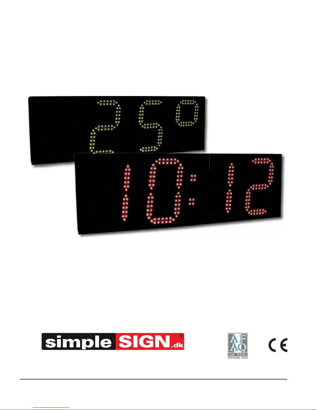
Time and Temperature Display Kit
Installation and Operating Manual
PO BOX
49340 TRÉMENTINES FRANCE
Tel. 33 (0)2 41 71 72 00
Fax 33 (0)2 41 71 72 02
www.bodet.com
Ref. 606252C
When receiving this product, check that it has not been damaged during transport and notify the carrier of any
reservations.
Bjødstrupvej 12A, DK 8410 Rønde
Tlf. +45 8637 3033 - [email protected]
Page 2
2
Table of contents
I - General description ...................................................................... 3
II - Electrical installation .................................................................... 4
III - Settings menu ............................................................................ 6
A - Main menu ....................................................................................................7
B - TIME menu : setting the time and date .........................................................8
C - PROG menu : adjusting brightness, temperature and alternation ................9
D - TECH menu : technician .............................................................................10
E - TEST menu : test and version display ........................................................14
IV - Technical specifications ........................................................... 15
V - Installation recommendations ................................................... 16
CAUTION : this equipment must be serviced by an approved technician. The guarantee
shall be cancelled if any modifications are made to this product.
This symbol means that you must consult this manual.
This symbol means that dangerous voltages are present.
Read the document concerning «General safety instructions and precautions for
the use of BODET products», in appendix, before installing this equipment.
Page 3
3
I - General description
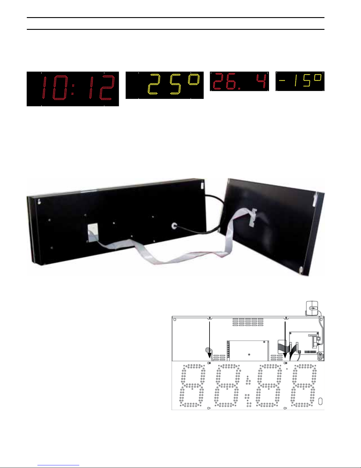
The LED kit H/T is a diode display unit showing the time, date and temperature as a
fixed or alternating display.
Four sizes are available with red or yellow LEDs : 30, 25, 20 and 15 cm.
This equipment can be fitted in single-side or double-side mode.
• The single-sided box includes the CPU board and the power unit. (This box is
thicker than the double-sided box).
• The double-sided box is supplied with the display unit only and with a flat cable to
be connected directly to the single-sided box.
The display kit must be integrated in
a sign with a protective pane on the
front.
Double-sided box
(the slimmer box)
Single-sided box
(the thicker box)
Rear view of the 2 boxes
Tip to open the box : release the screws of the
facade and put it on the 2 screws at the bottom
Page 4
4
II - Electrical installation
1. Open the box on the main face by removing the 4 screws to access the wiring of
the LED kit H/T.
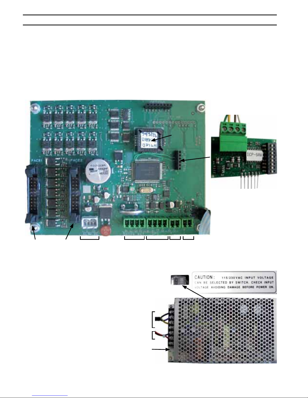
2. For double-sided operation, connect the flat cable to the connector for side 2 on the
CPU board.
3. Connect the peripheral devices to the CPU board (temperature probe, FI/DCF* and
GPS* synchronising antenna).
4. Connect the power unit to the mains power supply.
5. Close the box and reinstall the four screws.
(*) See the corresponding literature.
(**)The polarity of the power supply must conform with the screen-printed markings.
To side 1
main line
To power
unit **
To side 2
secondary
line
To external
option
To GPS
antenna
To FI/DCF
antenna
To
temperature
EPROM
CPU board
To HF receiver
Dips
HF receiver board
To 230 V or 110 V power supply
To CPU board
Power unit
Move the cursor to select the type of
mains power supply : 230V or 110V
The potentiometer setting must not
be modified in any circumstances.
Page 5
5
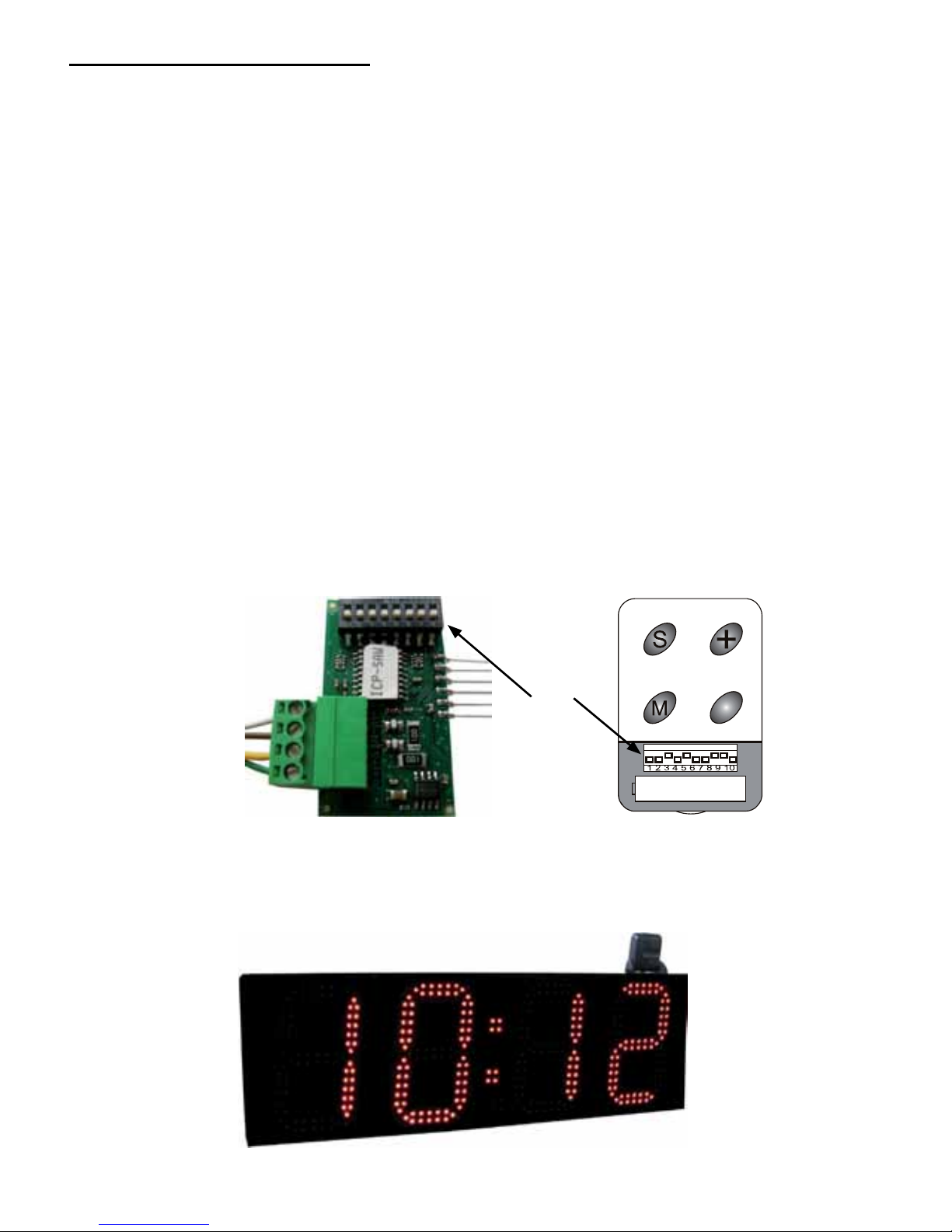
Wireless radio control console
The wireless radio control console is used for the remote control of the LED kit H/T
(within a range of 10 metres).
Setting the DIPs for HF receiver link and wireless console :
• Disconnect the power supply before performing this operation.
• Recognition between the console and the HF receiver on the board is established
via DIPs in order to avoid having the LED kit H/T controlled by another wireless
radio console that is not already recognised.
• Open the console. Position the first eight DIPs as desired on the HF receiver board
on the H/T LED board and the DIPs for the wireless console (placing them in the
same position as the eight DIPs on the two terminal blocks). DIPs 9 and 10 (on the
console only) must never be modified : position DIP 9 to ON and DIP 10 to OFF.
• Close the console and press a button. The HF receiver on the H/T LED board
is then configured so that it will only work with the console with the same DIP
configuration. This sequence is saved in memory even in case of a power failure.
• Change the console batteries every two years, on average : 12 V battery (type
A23).
• Note : a second HF radio control console may be used, in which case the DIPs on
the consoles and HF receiver board must be set to the same positions.
• Warning : the remote control may not function correctly in the presence of a strong
electromagnetic field.
(*) The HF radio receiver can be detached from the box to obtain better reception or to make it easier to
install the box. The HF radio receiver must not be moved further than 50 cm from the box. The receiver is
not watertight.
HF receiver board HF console
Dips
To HF
receiver*
HF receiver
Page 6
6
Temperature probe
The temperature probe must be placed in a well-ventilated location protected from the
sun and rain, preferably at the bottom of a totem. The position for the probe must always
be carefully selected to ensure that a correct temperature reading is obtained. Avoid
south-facing walls, metal parts and draughts. The temperature probe is supplied in
the box on the main face : it must be removed from the box.
The probe is factory adjusted to 20°C. (Caution : do not confuse degrees Celsius and
Fahrenheit). It may be necessary to modify, as follows, this setting depending on the
length of the cable :
• Place an accurate thermometer near the probe.
• Adjust the temperature, if necessary, using the offset function in technical menu.
III - Settings menu
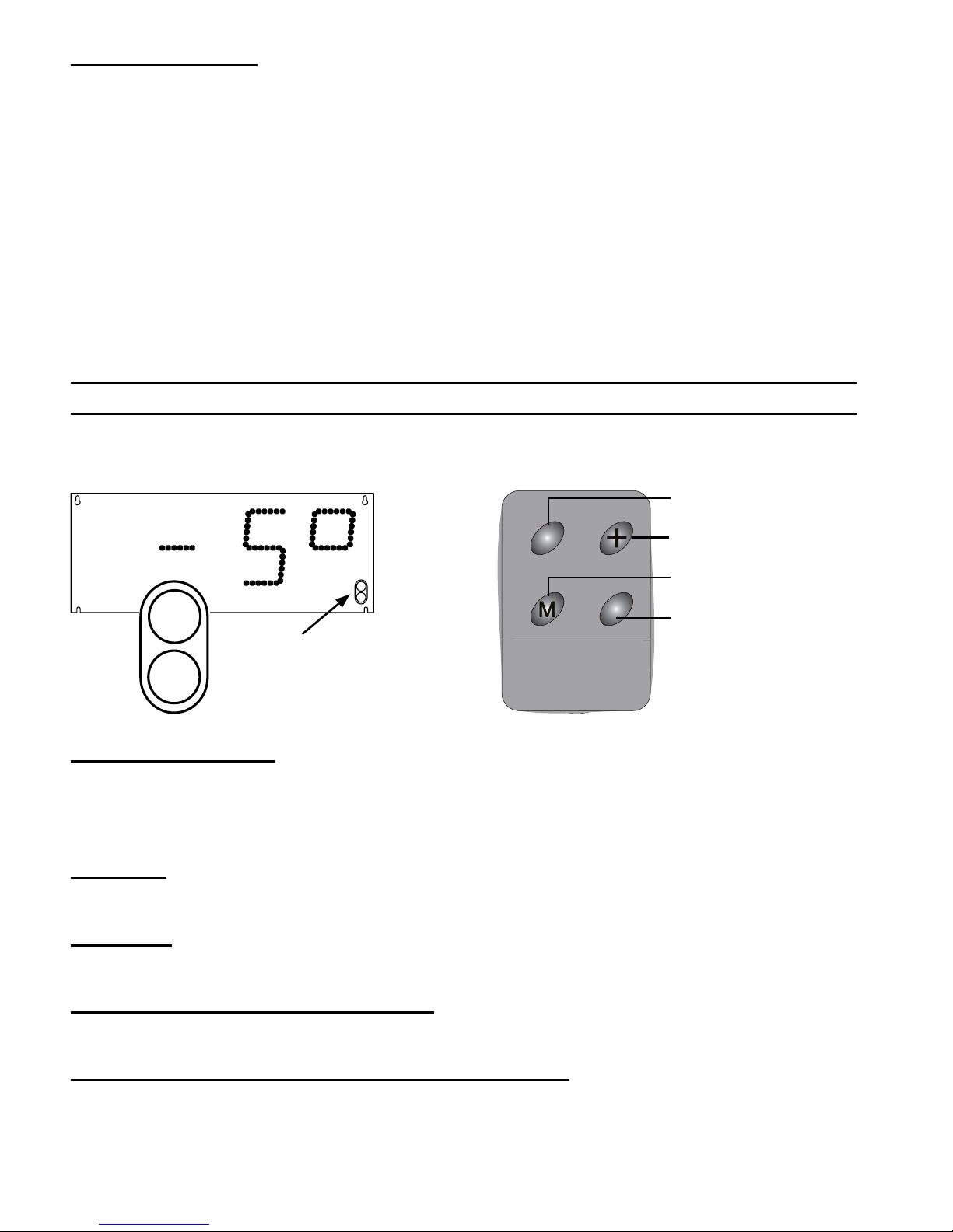
To define the LED kit H/T settings, use the two buttons on the front panel of the single
sided LED kit H/T or the HF radio control console.
[Select] or [S] button
- Long press (3 seconds) to access the programming menu (Time/Prog/Tech/Test).
- When in a menu, long press (3 seconds) to exit from the Prog menu.
- Short press to validate the previously selected menu or parameter.
[+] button
- Short press to select the next menu or parameter.
[M] button
- Short press to go straight to the first menu.
[ ] button (known as the blank button
- Perform a display test and display the EPROM version number.
General information on console and board buttons
- If no button is pressed for 30 seconds when entering data, the menu is exited
automatically without validating any modified parameter. A parameter is not
validated until the [S] button is pressed.
3
S : «S» button
+ :»+» button
M : menu button
: version / Test button
HF radio control console
Buttons on single-
sided box
SELECT
+
SELECT
+
Page 7
7
A - Main menu
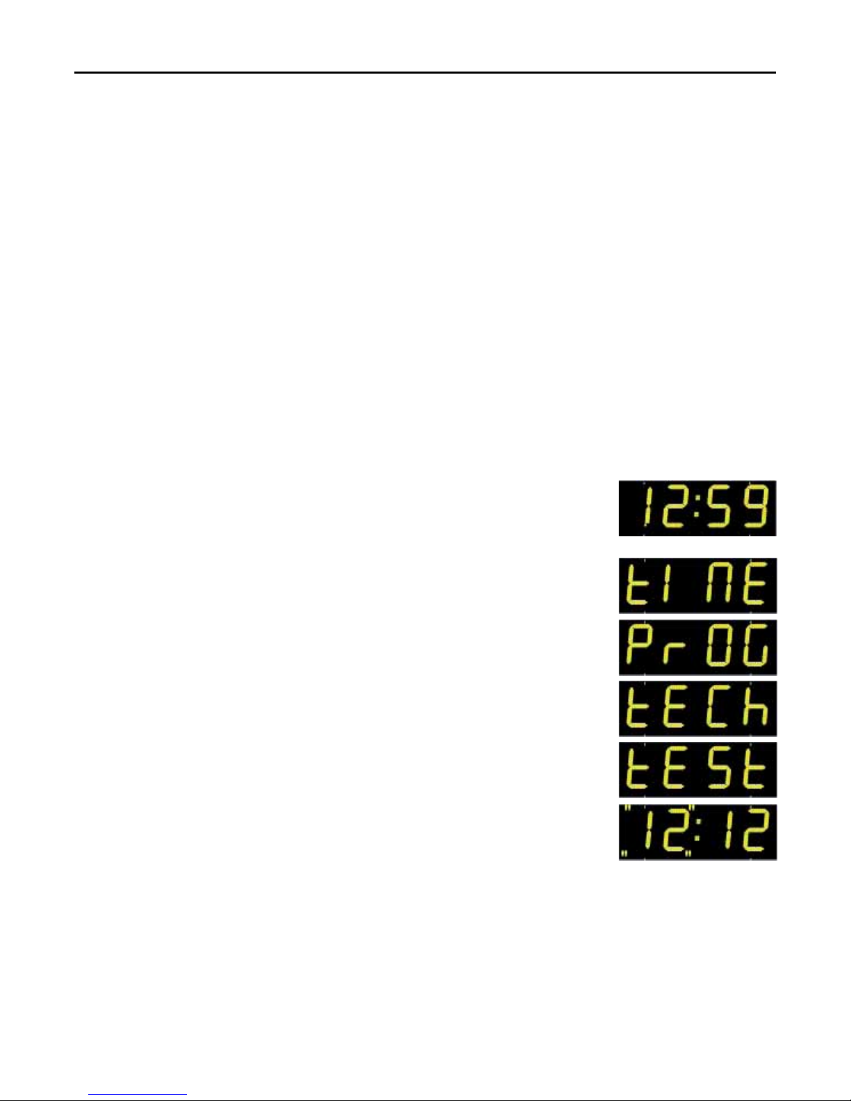
The main menu provides access to all the adjustment functions for the LED kit H/T
display unit. It contains four menus :
TIME : to set the time and date.
PROG : to adjust the LED brightness level on the display unit, add an offset value
to the temperature, or specify the information to be alternated on the
display unit.
TECH : to select 12/24 hour clock display mode, select the order of months/day
display (31.12 or 12.31), adjust the time synchronisation mode, adjust the
time difference and summer/winter time change options, modify the time
base and select the temperature unit : Celsius or Fahrenheit. Caution :
This menu is intended to be used by technicians only.
TEST : to test the display unit to check that each LED operates correctly and to
display the EPROM version number of the LED kit H/T.
1. The display unit is in rest mode, displaying the time,
temperature or date. Press the [S] button for 3 seconds (or
press [M] on the console).
2. The first menu to appear is the TIME menu. To go to the next
menu, press the [+] button*.
3. Press [S] to validate the choice of menu. Otherwise, press [S]
for 3 seconds to exit from the programming menu.
* Press the [ ] button to go directly to the TEST menu.
Page 8
8
B - TIME menu : setting the time and date
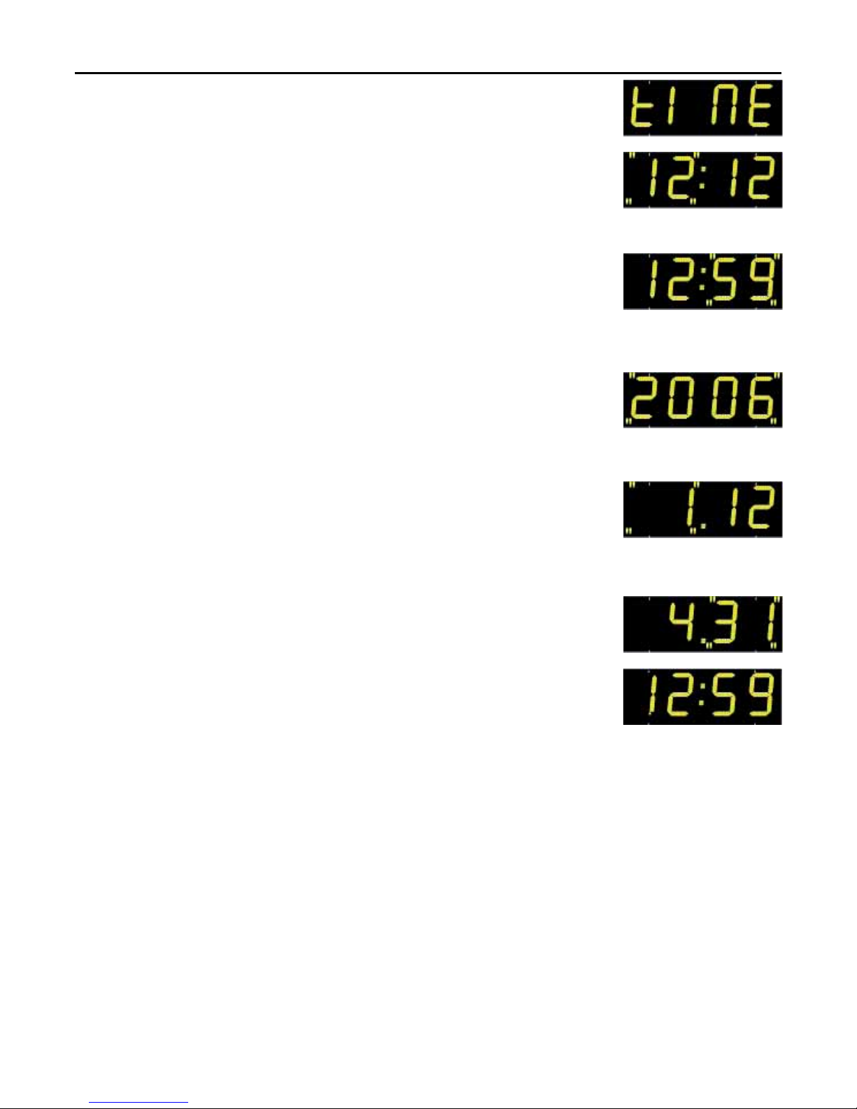
1. Enter the TIME menu (see page 6).
2. The hours blink (0 to 23). Modify with the [+] button.
3. Press the [S] button to validate the hours and to go on to the
adjustment of the minutes.
4. The minutes blink (0 to 59). Modify with the [+] button.
5. Press the [S] button to validate the minutes and to go on to
the adjustment of the year. The «seconds signal» (seconds
at 00) starts when the [S] button is released.
6. The year blinks (2000 to 2099). Modify with the [+] button.
7. Press the [S] button to validate the year and to go on to the
adjustment of the number of the day in the month.
8. The number for the day of the month blinks (from 0 to 31).
Modify with the [+] button.
9. Press the [S] button to validate the number and to go on to
the adjustment of the number for the month.
10. The number for the month blinks (0 to 12). Modify with the [+]
button.
11. Press the [S] button to validate the number for the month.
The display returns to normal mode with the newly modified
time and date.
Page 9
9
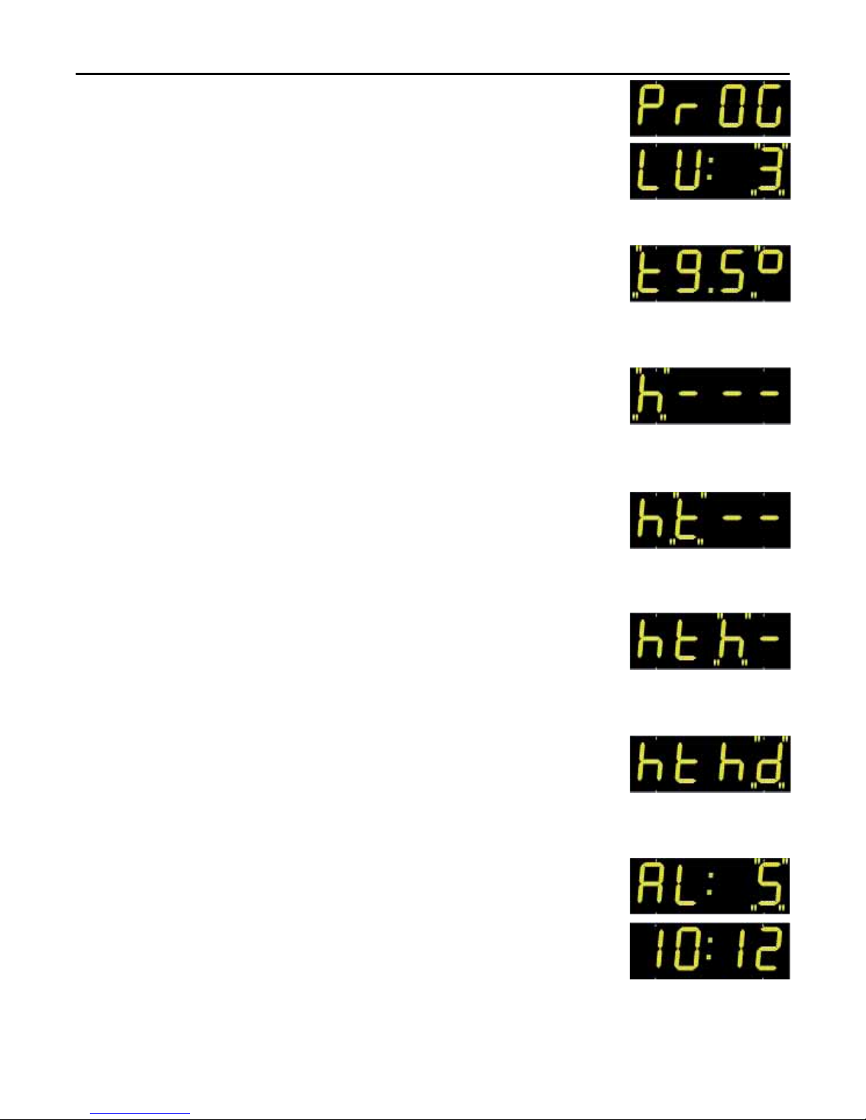
C - PROG menu : adjusting brightness, temperature and alternation
1. Enter the PROG menu (see page 6).
2. The brightness value blinks (from 1 to 3). Modify with the [+]
button. The brightness of the display is modified in real time.
3. Press the [S] button to validate the brightness and to go on to
the adjustment of the temperature offset.
4. The temperature offset blinks (from -9.5 to 9.5° in steps of
0.5°). Modify with the [+] button.
5. Press the [S] button to validate the offset and to go on to the
adjustment of the first alternation parameter.
6. The first alternation parameter blinks (h, t, d or -)*. Modify
with the [+] button.
7. Press the [S] button to validate the parameter and to go on to
the adjustment of the second alternation parameter.
8. The second alternation parameter blinks (h, t, d or -)*. Modify
with the [+] button.
9. Press the [S] button to validate the parameter and to go on to
the adjustment of the third alternation parameter.
10. The third alternation parameter blinks (h, t, d or -)*. Modify
with the [+] button.
1 1. Press the [S] button to validate the parameter and to go on to
the adjustment of the last alternation parameter.
12. The last parameter blinks (h, t, d or -)*. Modify with the [+]
button.
13. Press the [S] button to validate the parameter and to go on to
the adjustment of the alternation period.
14. The alternation period between information displays blinks
(from 2 to 6 seconds). Modify with the [+] button.
15. Press the [S] button to validate the alternation period. The
display returns to normal mode.
(*) h = time display t = temperature display date= date display - = no display.
Example of « h t d _ « setting : display of time, then temperature, then date, then return to time.
If «-» is selected, the next item of the information is displayed (no display in black). If the same letter is
entered twice in succession, the display time is doubled.
Page 10
10
D - TECH menu : technician
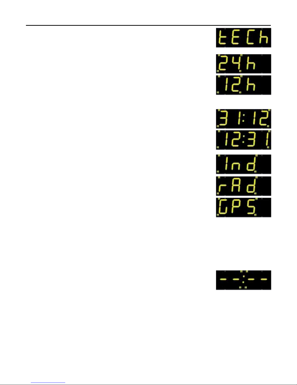
1. Enter the TECH menu (see page 6).
2. The 24 (or 12) hour clock time display mode blinks. Modify
with the [+] button.
3. Press the [S] button to validate the mode and to go on to the
adjustment of the day/month order.
4. The day/month or month/day order blinks. Modify with the [+]
button.
5. Press the [S] button to validate the order and to go on to the
selection of synchronisation mode.
6. The synchronisation mode blinks (independent «Ind», Radio
«rAd» or GPS «GPS»). Modify with the [+] button.
7. Press the [S] button to validate the synchronisation mode.
8. If rAd or GPS is selected, dynamic reception of the time is
displayed and constructed. If «Ind» is selected, this menu
does not appear.
9. Press the [S] button to validate dynamic reception and to go
on to the adjustment of time differences.
Page 11
11
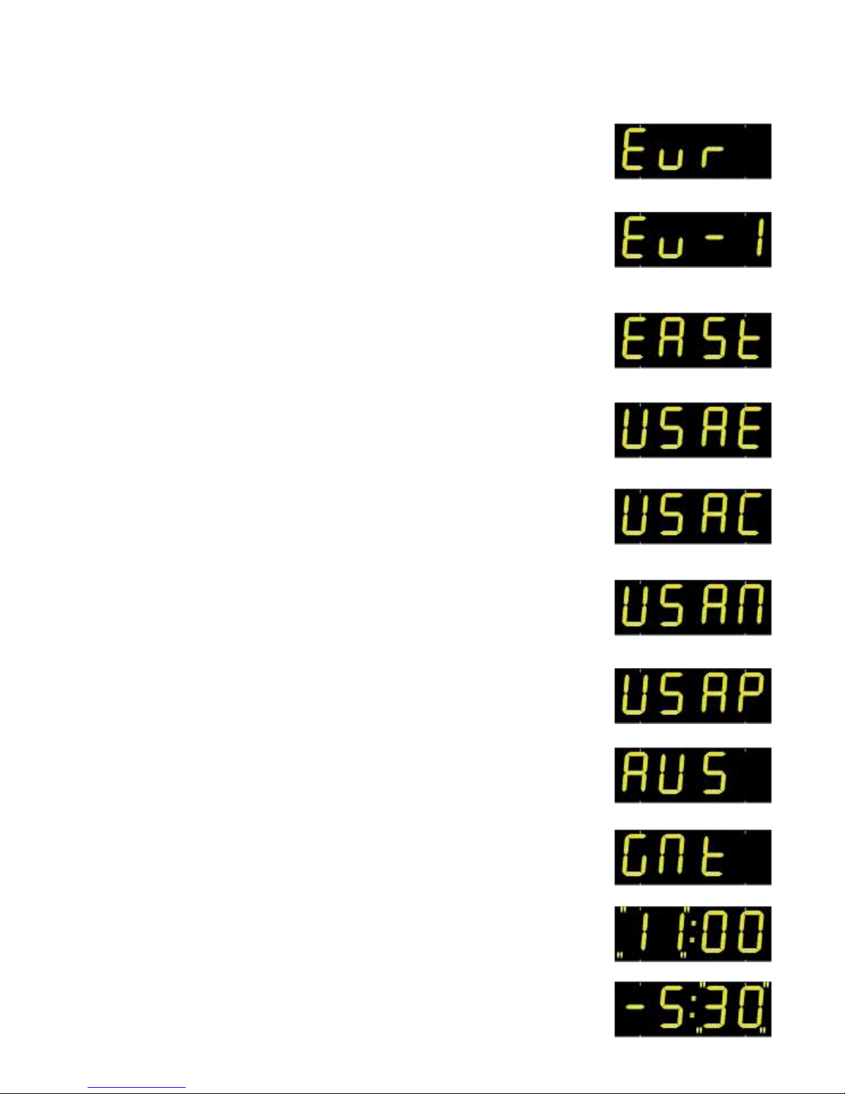
10. Choose a pre-recorded zone for time differences and summer/
winter time changes or choose programmable mode (Prog)
with the [+] button.
Central Europe zone “Eur” (France, Germany, etc.) (GMT +01 hour).
Winter to summer time = last Sunday in March at 2 a.m.
Summer to winter time = last Sunday in October at 3 a.m.
Western Europe zone “Eu_1” (Great Britain, Portugal, Republic of
Ireland) (GMT +00 hour).
Winter to summer time = last Sunday in March at 1 a.m.
Summer to winter time = last Sunday in October at 2 a.m.
Eastern Europe zone “EASt” (Greece, Finland, etc.) (GMT +02 hours).
Winter to summer time = last Sunday in March at 3 a.m.
Summer to winter time = last Sunday in October at 4 a.m.
USA Eastern zone “USAE” (New York, Toronto, etc.) (GMT -05 hours).
Winter to summer time = second Sunday in March at 2 a.m.
Summer to winter time = first Sunday in November at 2 a.m.
USA Central zone “USAC” (Chicago) (GMT -06 hours).
Winter to summer time = second Sunday in March at 2 a.m.
Summer to winter time = first Sunday in November at 2 a.m.
USA Mountain zone “USAM” (Denver) (GMT -07 hours).
Winter to summer time = second Sunday in March at 2 a.m.
Summer to winter time = first Sunday in November at 2 a.m.
USA Pacific zone “USAP” (Los Angeles) (GMT -08 hours).
Winter to summer time = second Sunday in March at 2 a.m.
Summer to winter time = first Sunday in November at 2 a.m.
Australia zone “AUS” (Sydney) (GMT +10 hours).
Winter to summer time = last Sunday in October at 2 a.m.
Summer to winter time = last Sunday in March at 3 a.m.
«GMt» programmable mode : mode to enter the time difference only. No
summer/winter time change is possible.
a. If GMT is selected, press the [S] button to validate.
b. The time difference hours blink (from -11 h to +11 h). Modify with
the [+] button.
c. Validate the time difference with the [S] button.
d. The minutes for the time difference blink (00 or 30). Modify with the
[+] button.
e. Validate the time difference with the [S] button.
Page 12
12
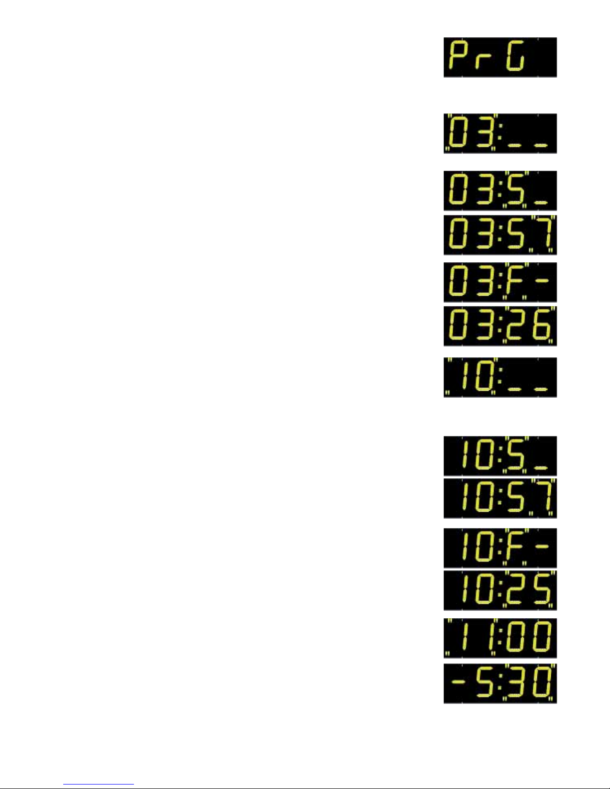
«PrG» programmable mode : mode to enter summer/winter and winter/
summer time change dates and time difference.
a. If the «PrG» menu is chosen, press the [S] button to validate.
b. The number of the month for the winter/summer time change blinks.
Modify with the [+] button.
c. Validate the month with the [S] button.
d. The third figure, corresponding to the day in the month for the
winter/summer time change blinks.
If the date is not fixed :
- Modify the third figure, corresponding to the number of the week
in the month (from 1 to 5) with the [+] button. Validate with [S].
- Modify the fourth figure, corresponding to the number of the day
in the week (from 1 to 7 : 1 Monday and 7 Sunday) with the [+]
button. Validate with [S].
If the date is fixed :
- Select F for the third figure with the [+] button. Validate with [S].
- Enter the number of the day in the month (from 1 to 31) with the
[+] button. Validate with [S].
e. The number of the month for the summer/winter time change blinks.
Modify with the [+] button.
f. Validate the month with the [S] button.
g. The third figure, corresponding to the day in the month for the
summer/winter time change, blinks.
If the date is not fixed :
- Modify the third figure, corresponding to the number of the week
in the month (from 1 to 5) with the [+] button. Validate with [S].
- Modify the fourth figure, corresponding to the number of the day
in the week (from 1 to 7 : 1 Monday and 7 Sunday) with the [+]
button. Validate with [S].
If the date is fixed :
- Select F for the third figure with the [+] button. Validate with [S].
- Enter the number of the day in the month (from 1 to 31) with the
[+] button. Validate with [S].
h. The hours of time difference blink. Modify with the [+] button (from
-11 h to +11 h). Validate with the [S] button.
j. The minutes blink. Modify with the [+] button (00 or 30). Validate
with the [S] button.
Page 13
13
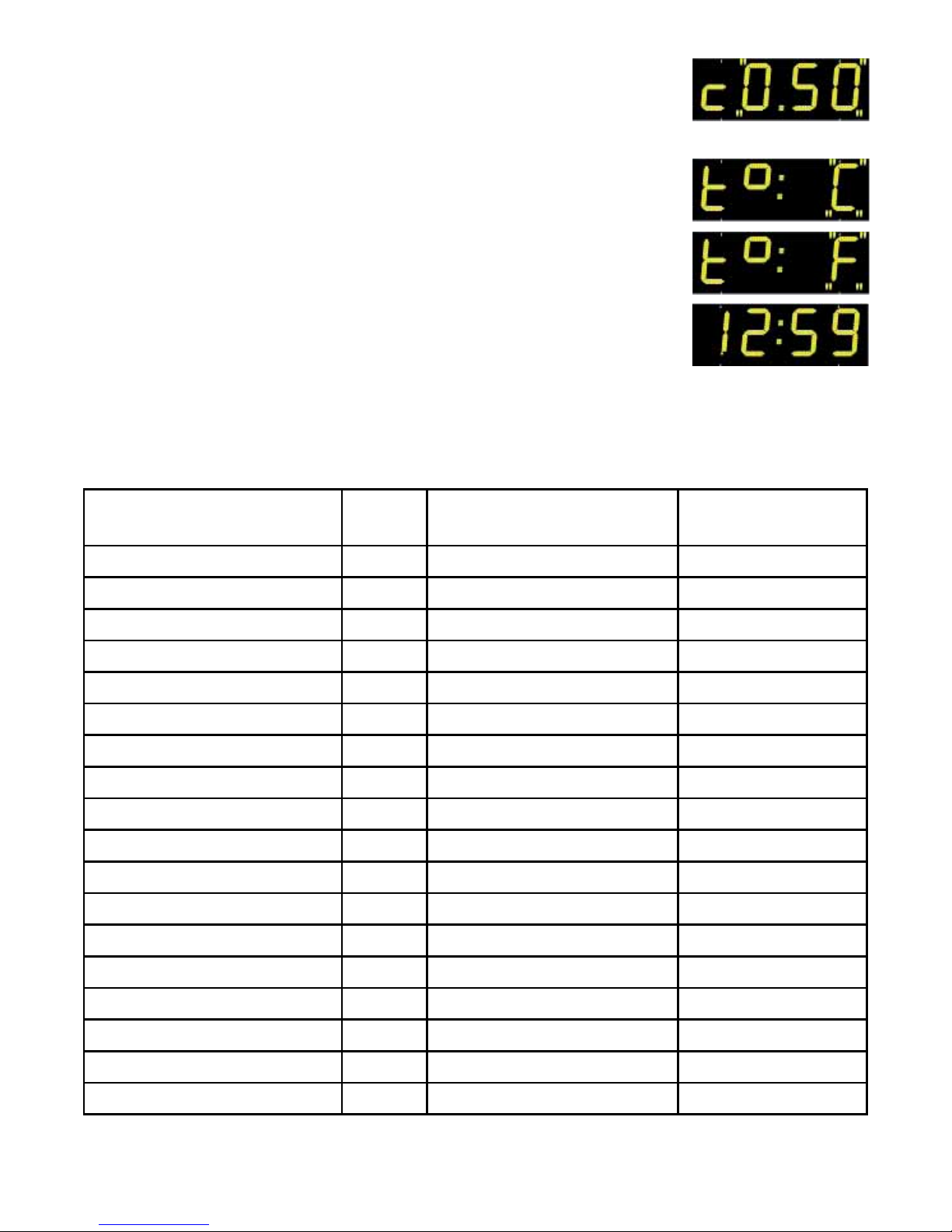
11. The time base correction value blinks (in steps of 50 ms).
Modify with the [+] button. The time difference is taken into
account whatever synchronisation mode is used (including
radio).
12. Press the [S] button to validate the difference and to go on to
the choice of synchronisation temperature unit.
13. The temperature unit, either degrees Celsius «C» or
Fahrenheit «F», blinks. Modify with the [+] button.
14 Press the [S] button to validate the temperature unit. The
display returns to normal mode.
Appendix for time differences
Select the reference country for summer/winter time changes and time difference according to the city whose
local time is to be displayed.
CITY Zone Reference zone Time difference /
GMT
LOS ANGELES USAP United States / Canada -08
MEXICO USAC United States / Canada -06
CHICAGO USAC United States / Canada -06
NEW YORK, TORONTO USAE United States / Canada -05
BUENOS AIRES GMT No change -03
RIO DE JANEIRO PRG Programmable mode -03
LONDRES EU_1 Europe 00
PARIS (*) EUR Europe +01
HELSINKI, A THÈNES EAST Europe +02
JOHANNESBURG GMT No change +02
MOSCOU EAST Europe +03
SINGAPOUR (**) GMT No change +08
TOKYO, SÉOUL GMT No change +09
SYDNEY AUS Programmable mode +10
WELLINGTON PRG Programmable mode +12
PARAGUAY PRG Fixed date (each year) -04
TÉHÉRAN PRG Fixed date (each year) +3.30
BOMBAY GMT No change +5.30
(*) Paris and the following cities: Frankfurt, Madrid, Stockholm, Oslo, Zurich, Milan, Amsterdam, etc.
(**) SINGAPORE, and the following cities: Taipei, Bangkok, Hong-Kong, Kuala Lumpur, Beijing, etc.
Page 14
14
E - TEST menu : test and version display
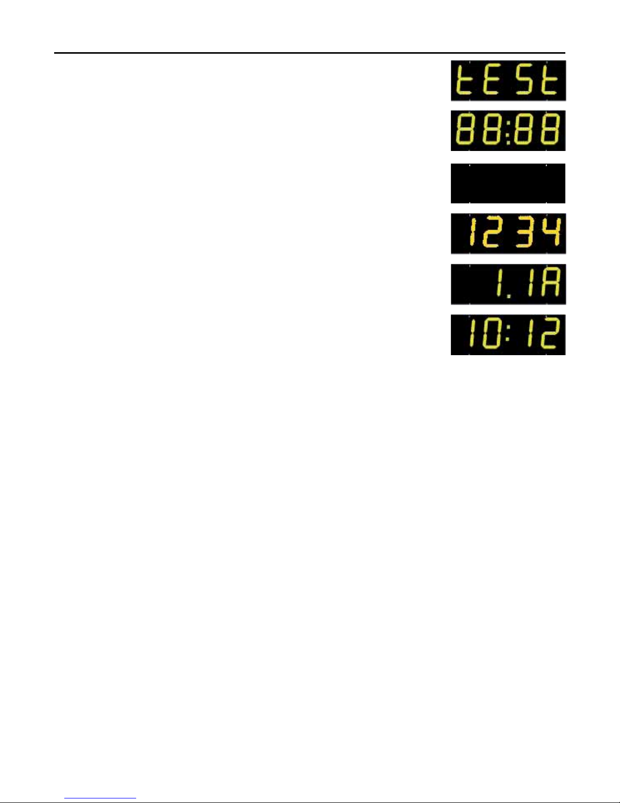
1. Enter the TEST menu (see page 6).
2. All the LEDs should light up.
3. Press the [S] or [ ] to go on to the next test.
4. All the LEDs should go out.
5. Press the [S] or [ ] button to display the version.
6. Display of the position of each digit.
7. Display the EPROM version number of the LED kit H/T.
8. Press the [S] or [ ] to return to normal mode.
Page 15
15
IV - Technical specifications
Models
• Single-sided display line (SS) with control by 2 buttons on the box.
• Secondary display line for double-sided mode (DS).
• Available in 15, 20, 25 or 30 cm sizes, in red or yellow, in SS or DS.
• Optional HF radio control console.
Features
• Fixed or alternating display of time, date or temperature.
• Adjustable alternation period (2 to 6 seconds).
• Automatic brightness adjustment for sun, cloud or night.
• Temperature probe supplied with 5 metres of cable.
• Optional radio synchronisation by France Inter , DCF or GPS antenna (independent
time base precision of 0.2 second/day).
• Power supply : 110/240 V 50/60 Hz.
• Black flush-fitting case including LED display units, power unit and control board.
The display kit must be fitted in a sign with a protective pane on the front.
• Indoor or outdoor operation in a watertight totem.
• Tropicalised PCBs.
• Operating temperature from -20 to 50°C.
Settings
• Time display in 12 or 24 hour clock mode.
• Temperature in degrees Celsius (°C) or Fahrenheit (°F).
• Automatic summer/winter time change.
• Display test menu.
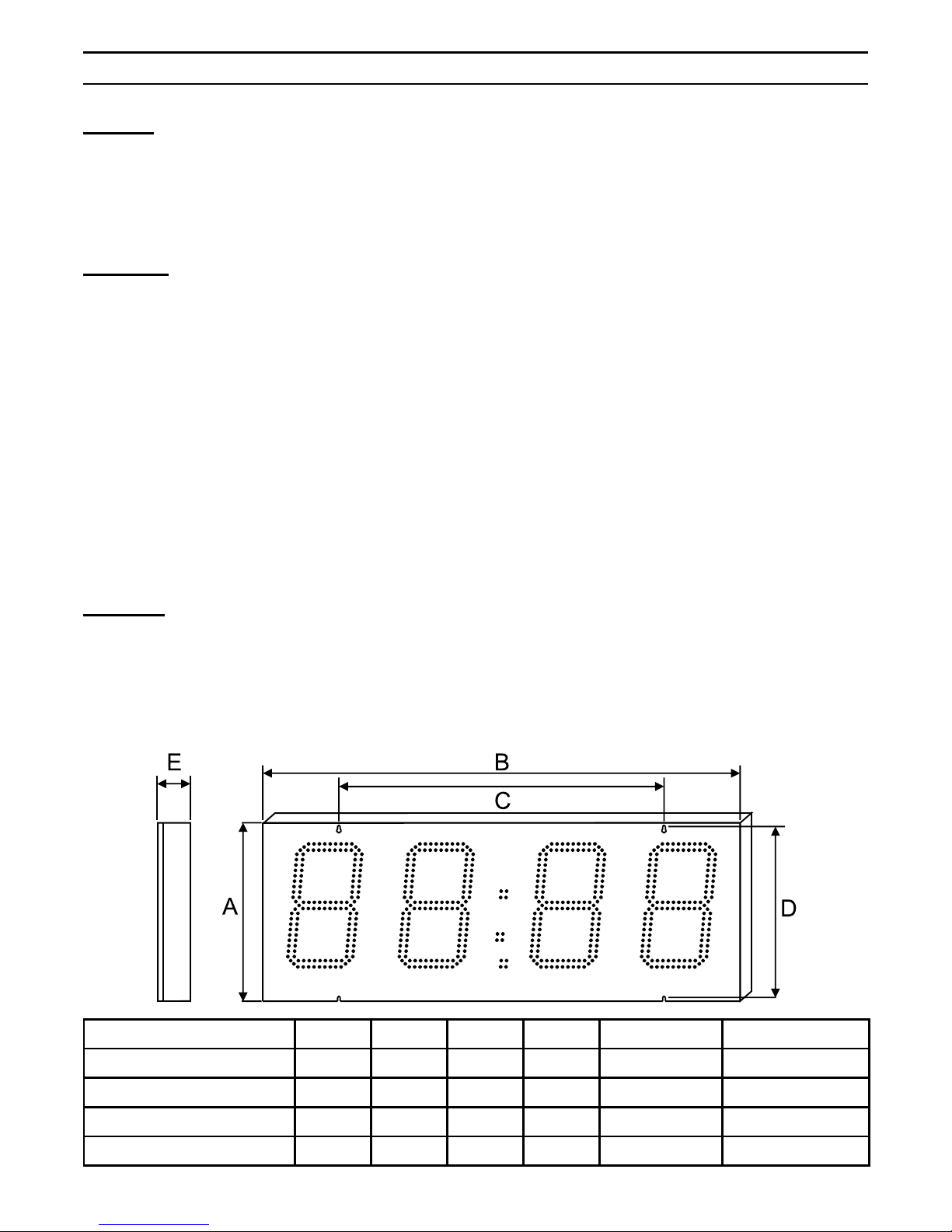
Dimensions in mm A B C D E (SF / DF) Visibility in m
Led kit H/T 15 cm 235 550 520 218 75 / 20 60
Led kit H/T 20 cm 235 730 700 218 75 / 20 80
Led kit H/T 25 cm 336 970 650 320 75 / 20 100
Led kit H/T 30 cm 428 1145 780 410 75 / 20 120
Page 16
16
V - Installation recommendations
A - Brightness
As far as possible, avoid placing the display unit near direct light sources (street lamps,
etc.) to avoid interference with the automatic brightness adjustment.
B - Installation principle
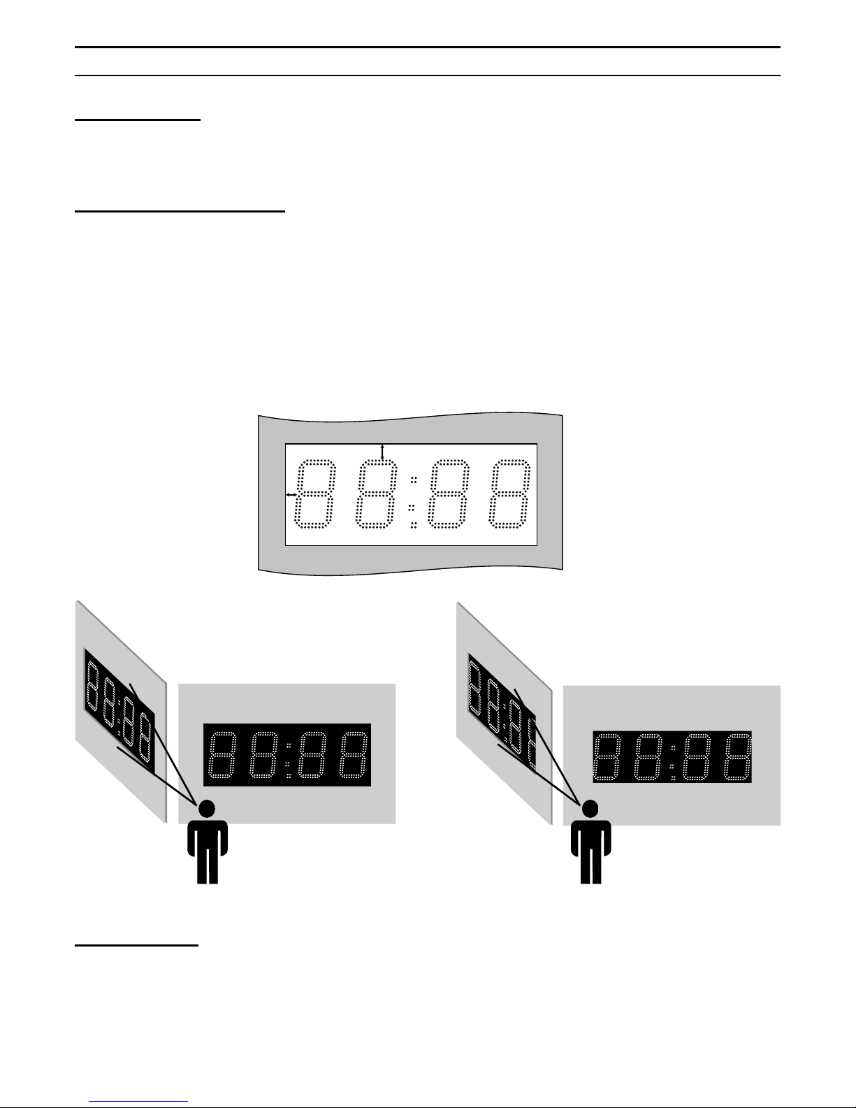
If a non-reflective pane is used in front of the LED kit H/T, it should be placed 2 or 3 cm
in front of the figures.
To ensure correct reading of all the figures, allowing for parallax errors, the distance
between the LED digits and the external structure must be properly calculated to allow
easy lateral and vertical reading. For cutouts, sufficient space must be allowed around
the digits (A) (about 2 cm).
C - Ventilation
As the LED kit H/T must be fitted in a water tight structure, it is important to provide for
ventilation in order to avoid condensation.
A
A
Correct cutout
Incorrect cutout
 Loading...