

Page 1
INSTALLATION INSTRUCTIONS
FOR THE MOTORIZED SIMPLE PUMP SYSTEM
(LINEAR BEARING LINK DRIVE OPTION)
LAST UPDATED: November 13, 2017
(The following instructions are very detailed, and should tell you everything you
need to know. If you have questions, please phone 775-265-1220.)
1140 Amarillo Drive, Gardnerville, Nevada 89460-7504
page 1 © Simple Pump Company
SIMPLE PUMP COMPANY
Phone: 877-492-8711 (toll free) or 775.265.1220
Mon-Fri: 8am-5pm PST
Fax: 888.826.1444 (toll-free)
[email protected] • www.simplepump.com
Page 2

TABLE OF CONTENTS
Introduction 2
Specifications 3
Recommended Operating Environment and Applications 3
Section 1: Unpacking and Tools required 5
Section 2: Unpacking & Inspection 5
Section 3: Preparing Your Existing Pump 6
Section 4: Installation 10
Section 5: Electrical Connection 13
Section 6: Operation 13
Section 7: Maintenance & Trouble-Shooting 13
Section 8: Warranty 14
INTRODUCTION! !
Thank you for purchasing a Simple Pump gear motor assembly. This Motorized Pump with Linear
Bearing Link Drive (LBLD) is designed for use with the Simple Pump model 100 and 125 hand pumps.
When assembled and installed on the Model 125, the gear motor is capable of delivering 2.0 gallons of
water per minute (GPM) from as deep as 175 feet. Installed on the Model 100, it delivers 1.3 GPM.
The motor is available in two models, 12 volt and 24 volt DC. These instructions cover both versions.
The linear bearing link drive translates the rotary action of the Simple Pump 12 or 24 volt DC gear
motor to move the pump rod up and down on a precision ground and polished stainless shaft guided
by two linear TEFLON bearing carriers.
page 2 © Simple Pump Company
Page 3

SPECIFICATIONS
WHEN POWERED WITH 12V DC
Motor Rating .140 HP continuous
Gear Ratio 30:1
Output Torque 154 in/lbs. continuous
Output Torque Maximum 175 in/lbs. @ 56RPM @ 16.3 amps
Nominal Output RPM 57%
Efficiency 59.5
Full Load Motor Current 14.6 amps
Allowable Voltage Range 11.5 to 15 VDC
Typical temperature of casing, operating
in 72˚F ambient 110˚ Fahrenheit
WHEN POWERED WITH 24V DC
Motor Rating .151 HP continuous
Gear Ratio 30:1 @ 91.0% efficiency
Output Torque 195 in/lbs. continuous
Output Torque Maximum 400 in/lbs. @ 45.9RPM @ 16.63 amps
Nominal Output RPM 60.1
Efficiency 64.24%
Full Load Motor Current 7.32 amps
Allowable Voltage Range 24 to 30 VDC
Typical temperature of casing, operating
in 72˚F ambient 110˚ Fahrenheit
RECOMMENDED OPERATING ENVIRONMENT AND APPLICATIONS
AMBIENT TEMPERATURE
DC motors operating in ambient temperatures above 100˚F lose operating efficiency -- the hotter the
ambient temperature, the less efficient. If the temperature at the planned site regularly peaks above
100˚F, we recommend operation of the motor in shade.
CONSISTENT SOURCE OF DC POWER
As with any DC motor, precaution must be taken to prevent operation under low voltage conditions -below 11.5V with the 12VDC model, 23.5V with the 24VDC model.
IDEAL APPLICATION TO MINIMIZE WEAR
Ideally, when pumping from any significant depth, you should not operate the Motorized System (LBLD
Option) configured to pump into a pressurized system. The most difficult part of delivering water to a
page 3 © Simple Pump Company
Page 4

pressurized system is moving it out of the well. Once at ground level, the water can be delivered by a
booster pump available at a fraction of the cost of the Motorized System (LBLD Option). The only
other additional cost is the tank for ambient storage, i.e., not under pressure.
The water lifted out of the well is pumped into the ambient storage tank by the Motorized System.
Booster pumps designed specifically to pump into a pressure tank are available from a number of
vendors, e.g. Dankoff, Surflo and Jabsco. Many such pumps cost less than $150.
Configuring like this also raises the overall reliability of the system. Most notably, booster pumps
include an integrated pressure sensor. It signals the booster pump to turns the pump on and off,
according to a target pressure, when water is demanded from the pressure tank.
By contrast, any Simple Pump provides water with a pulsed delivery, and therefore varying pressure,
making the task of regulating flow to the pressure tank more difficult.
UNSUPPORTED APPLICATIONS
Operating the Motorized System (LBLD Option) in certain configurations voids its warranty.
‣ Pumping into pressure greater than 50 psi.
‣ Directly connected to batteries without a low voltage disconnect that prevents the supply of current
below 11.5V or 23.5V, depending on whether the motor accepts 12VDC or 24VDC as input.
SUPPLYING POWER RELIABLY
The task of supplying power above the 11.5V and 23.5V (for 12VDC and 24VDC systems) thresholds is
more complex than many anticipate, particularly with solar-powered systems. Because most
configurations using the Simple Pump Motorized System are powered using solar panels, only solar is
discussed in this section.
Keeping voltage above 11.5 or 23.5 volts seems simple: Provide enough power, with a device to
regulate its delivery. However, a number of factors influence what constitutes “enough power” when
considering how to configure an off-grid application:
‣ Days of autonomy: The total number of days the system must provide power without sunny days, in the
worst-case scenario. For example, if the system will be used throughout the year, with expected water
usage the same throughout the year, the radiation expected on the winter solstice is used to for the
worst-case calculation.
‣ Solar radiance: Factor in both how far north (latitude) and expected cloud cover.
‣ Daily water used. If more water is used when radiation levels are higher -- e.g., more for gardening
starting in March -- then projected water consumption must be compared against expected radiation at
multiple points in time throughout the year.
‣ Location: Separate from how much solar radiance a location receives, those north of 45˚N (about as far
north as Columbus, Ohio, should should also have a system that can be pivoted manually, to account for
the sun’s much lower angle in the sky in winter.
‣ Distance between power source and consuming machine.
‣ Worst-case cold: If batteries are used, requirements can jump up to 1.6 times more than would be
required in a warm climate.
page 4 © Simple Pump Company
Page 5

PROFESSIONAL HELP?
If this is more complex than you planned, there are alternatives.
Anyone with NABCEP (North American Board of Energy Practitioners) certification, and experience
configuring off-grid systems, is almost certainly qualified to help. However, while all NABCEP-certified
professionals must learn about off-grid systems, most pursue grid-tie solar systems -- a very different
field. This is why it is important to ask about recent experience.
SECTION 1: UNPACKING AND TOOLS REQUIRED
CONTENTS OF BOX
LBLD mechanism with cover, delivered as one piece.
White protective over wrap on cover to be removed before installation
(6) 8-32x1/2 SS socket head cap screws (SHCS) fasten cover on mounting plate
(1) 3/4" x 36" stainless steel rod
(4) 1/4-20x3/4" SS SHCS mounting bolts
(3) 25A ATO/ATC automotive-style fuses (for 12V system), OR
(3) 15A ATO/ATC automotive-style fuses (for 24V system)
TOOLS REQUIRED
(4) Allen wrenches: 9/64", 3/16", 1/4", 5/16"
(2) Channel locks
(1) Medium Phillips screwdriver
SECTION 2: UNPACKING & INSPECTION
Carefully remove the LBLD mechanism, rod, bolts (in poly bag) and fuses from the shipping box.
Using the 9/64" Allen wrench, remove the six screws that attach the cover. Remove the white
protective over wrap from the cover.
page 5 © Simple Pump Company
Page 6
SECTION 3: PREPARING YOUR EXISTING PUMP
Your Simple Hand Pump should already be installed and pumping water without any binding and with
an overall smooth operation prior to attempting to install this gear motor.
You should confirm that your pump is delivering at least one gallon of water with approximately 25
strokes with the lever handle system (model 100L). If you have the model 125L, your pump should be
delivering about one gallon of water in approximately 14 complete strokes.
Starting with a fully-functional lever-arm pump, what follows are the step-by-step installation
instructions.
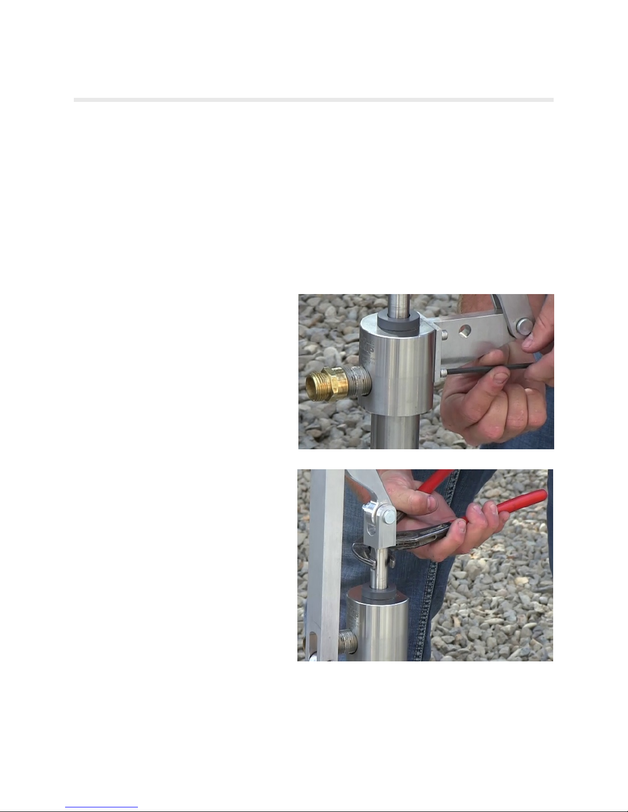
REMOVE THE LEVER ARM MECHANISM
Using the 3/16" Allen wrench, remove each
of the four fasteners holding the lever arm
mechanism to the pump head.
Remove the lever arm bracket and lever
(they should still be connected) from the
3/4" stainless rod. The direction you screw is
the opposite of normal -- turn clockwise to
remove, rather than the normal
counterclockwise.
page 6 © Simple Pump Company
Page 7
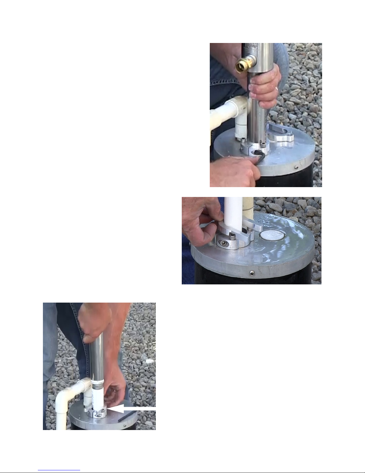
Using the 3/16" Allen wrench, loosen the pinch bolt and
the 3 mounting bolts on the split flange enough to pull the
pump head (including riser tube) up out of the well.
While holding the pump head by the riser tube,
seat the safety tool securely in the split flange.
page 7 © Simple Pump Company
Then, slowly lower the bell end of the top drop pipe into
the safety tool (left).
Page 8
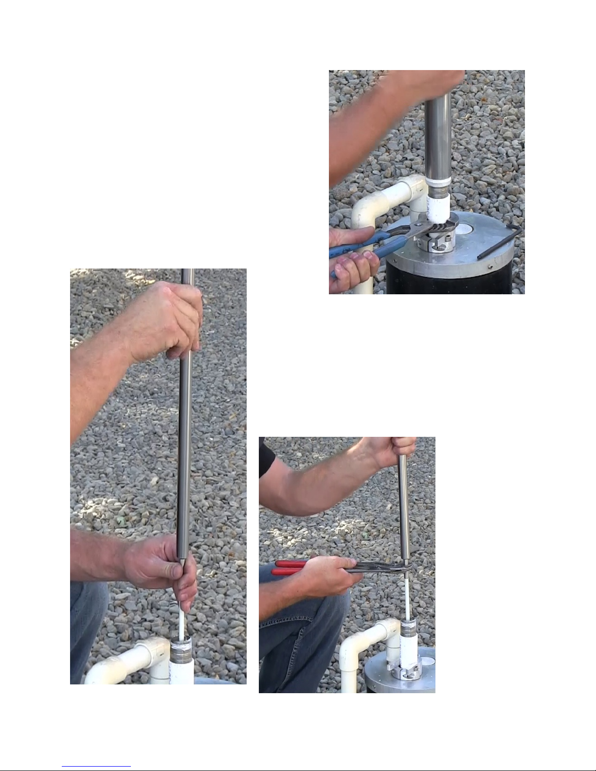
Use a channel lock to remove the riser tube and pump
head. This allows access to the 3/4" stainless rod.
Do not remove the stainless nipple.
Disconnect the 3/4" stainless rod from the topmost sucker
rod (left).
The stainless rod shipped with this Motorized Pump with
Linear Bearing Link Drive is longer than the lever arm
stainless rod just removed. Attach the longer 36" rod to the
top sucker rod.
page 8 © Simple Pump Company
Page 9
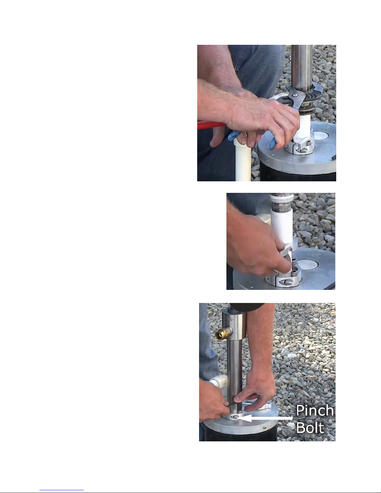
Reinstall the pump head and riser tube. Secure it
firmly on the stainless nipple that is attached to
the topmost drop pipe.
Lift the riser tube (and pump head), and then remove the
safety tool.
Lower the riser tube so that at least 6 inches of
riser tube are below the split flange on the cap.
Tighten the pinch bolt and 3 mounting bolts (right).
page 9 © Simple Pump Company
Page 10
SECTION 4: INSTALLATION
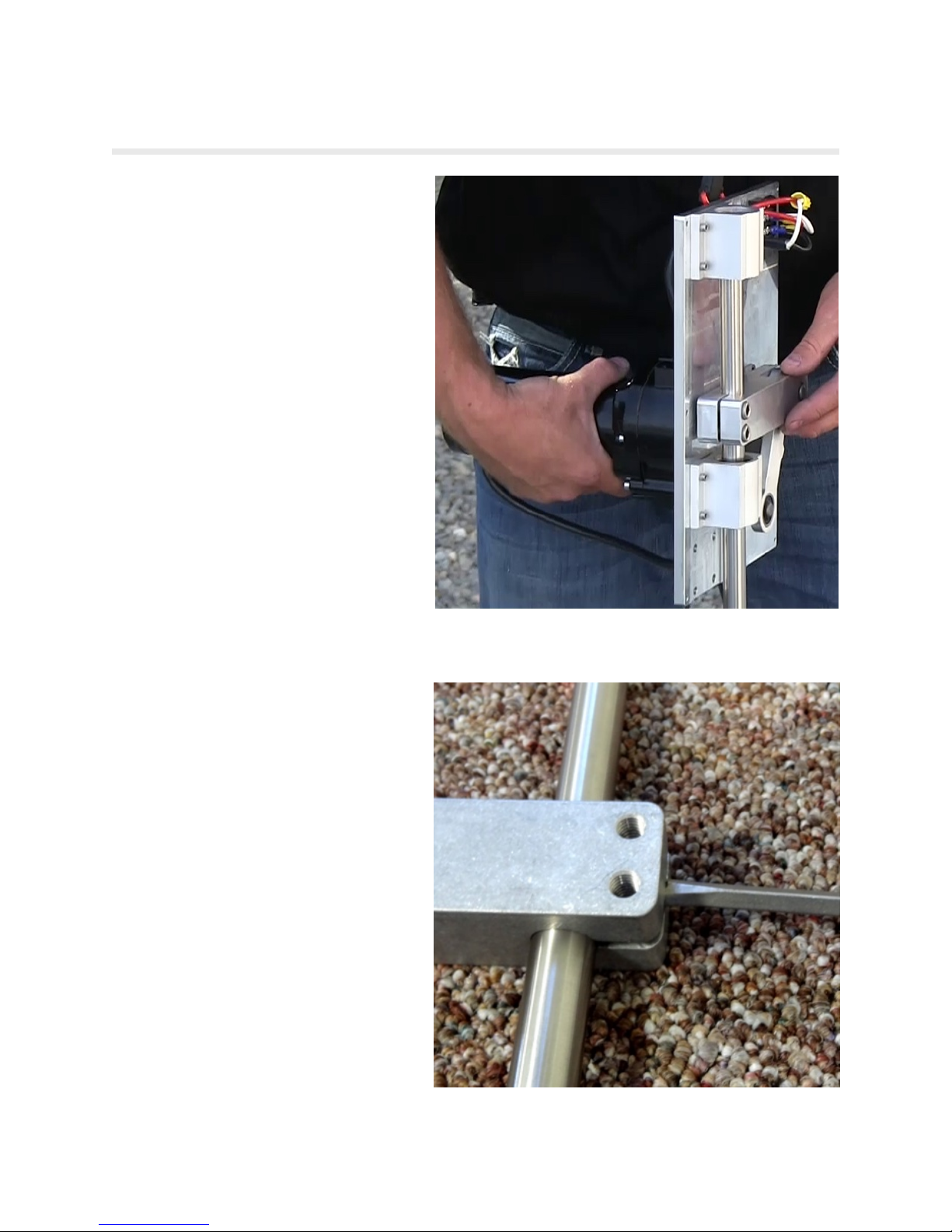
Lower the Linear Bearing Link Drive
Mechanism (LBLD) so that the stainless
rod is inserted into 3 openings.
‣ Orientation: When you lower the LBLD
onto the stainless rod, the electric
terminals are on the top side.!
‣ The DC motor faces away from the pump
head.
As the mechanism is lowered down, the
stainless rod moves through, in order:
‣ The lower linear bearing.
‣ The yoke.
‣ The top linear bearing.
The tolerances are tight between the yoke
ID and shaft OD. You MAY need to splay
the gap in the yoke slightly, as shown in
the photo.
page 10 © Simple Pump Company
Page 11
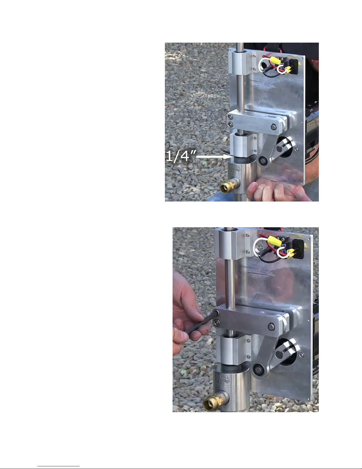
Rotate the Linear Bearing Link Drive
Mechanism around the pump head until
the holes for the four mounting bolts are
aligned.
There is 1/4" of space between the
bearing housing and the top of the rod
gland when the holes are aligned. The rod
gland is the topmost exposed component
on the pump head.
Screw the four 1/4-20x3/4" SS SHCS
mounting bolts through the holes just
aligned, fastening the mounting plate to
the pump head.
Lift up the 3/4" diameter SS pump rod 2
inches to make sure that the piston is not
sitting on the ball at the bottom of the pump
cylinder.
Then using a 5/16" Allen wrench, tighten the
two stainless steel socket head cap screws on
the yoke.
This pinches the yoke so it is fastened to the
stainless rod.
page 11 © Simple Pump Company
Page 12
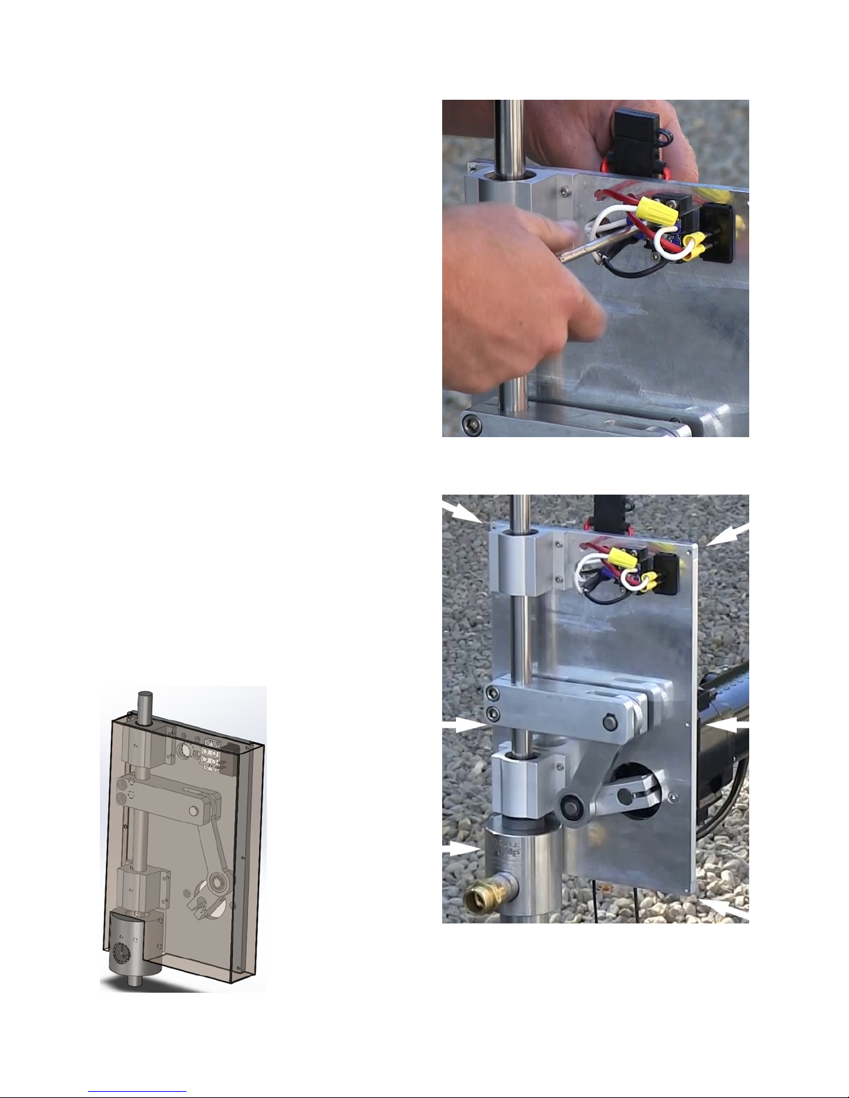
Attach your 12V or 24V power source to the
terminal strip.
Attach the cover to the LBLD mechanism.
Use your 9/64" Allen wrench for the (6) 8-32 SS
SHCS that attached the cover the the mechanism’s
mounting plate.
Diagram below shows how the cover fits onto the
mounting plate.
page 12 © Simple Pump Company
Page 13

SECTION 5: ELECTRICAL CONNECTION
The two wires coming out the bottom of the gear motor are to be supplied with 12 VDC or 24 VDC
power. Make sure that your supply wiring is at least 16 gauge and can maintain a minimum of 11.5
volts with the motor at a full load of 15 Amps. Note that the greater the distance to the power source,
the higher gauge wire required. Determining what you need may require a professional.
The white wire is the positive (+) power lead and the black is the negative (-). When working on the
power connection, put the switch next to the motor in the off position by pushing the button on the
bottom side and remove the fuse by pushing and turning it counter-clockwise.
CAUTION: Provisions need to be made in your power supply to prevent operation of the motor when
voltage is below 11.5 volts, such as when the battery is nearly discharged. This is up to you or to the
professional you hire.
SECTION 6: OPERATION
Once the power has been connected, install the fuse and attach the cover. During the break-in period,
leave the pump outlet open or pump through a drinking-water quality garden hose unrestricted. We
recommend a break-in period of 6 hours.
SECTION 7: MAINTENANCE & TROUBLE-SHOOTING
PROTECTION FROM WEATHER
In the standalone motor assembly, the DRIVE has a cover. The motor should also be provided some
protection. Alternatives could be
- a small roof with open sides
- a small pump "house" that just covers the well head and pump
- a full-sized pump house
FUSE
As long as the gear motor system is pumping correctly and not causing the motor to overload, no
maintenance is required. If the mechanism experiences a bearing failure for any reason, the motor
protection fuse will blow. It is extremely important to replace the fuse with only a 25 amp ATO/ATC
automotive style fuse (if 12VDC version) or 15 amp ATO/ATC automotive style fuse (if 24VDC version).
Using a higher amperage fuse will overheat the motor and damage the gears. The motor normally
operates at around 100-110º F.
page 13 © Simple Pump Company
Page 14

If the fuse has blown for any reason, remove the cover. Lift the stainless rod up and down, by hand.
How freely it moves is an indication of what the motor is working against. The typical reason for
difficult movement is pump binding.
Remove the motor mechanism and stroke the pump rod by hand. It should require about 40 lbs. of
lifting effort for each 100 feet of static water level depth. If the effort is any more than this, remove
the pump head and try again to determine if the problem is in the head.
If you suspect your system is not behaving as it should, do not hesitate to call Simple Pump.
(877.492.8711)
ONGOING MAINTENANCE
As long as the Motorized System with the LBLD is pumping correctly and not causing the motor to
overload, no maintenance is required for the LBLD motor component that is the subject of this
manual.
The pump’s seals must be replaced periodically -- typically every 3 to 7 years. (It can be more
frequent for industrial applications, or any application pumping water with a significantly non-neutral
pH, or high particulate levels.) Note that all of these are those that must be replaced on any Simple
Pump system, no matter what configuration -- driven by hand, or motor. If the flow rate of your pump
starts to fall, replacing the seals may well be the solution. Information about the periodic replacement
of seals can be found in the INSTALLATION AND MAINTENANCE manual for the hand-operated system.
There is no requirement to oil any of the LDBD system components. Optionally, if you have the cover
off, you can apply a bit of lubricating oil on the two points where ball bearings in the drive move
during operation. However, do not under any circumstances apply oil to the linear bearings, or the
3/4" x 36" stainless steel rod that moves up and down within those two linear bearings. Also, there is
no need to lubricate any component or surface on the motor itself.
SECTION 8: WARRANTY
The gear motor assembly is warranted against defective materials and workmanship for a period of 1
year from the date of purchase. The motor load must not be exceeded, and all instructions must be
adhered to.
page 14 © Simple Pump Company
 Loading...