

Simple Motors Kit 9, Kit 8 Assembly Instructions Manual
Assembly Instructions: Kit #9
Kit #9 is essentially Kit #8 where with a simple turn of the knob you can switch between four
differ ent motors:
• R – Regular reed switch motor
• T – Reed switch motor with the transistor
• H – Hall Effect motor
• O – Motor with optical control
If you are adding the switch to already assembled Kit #8 please note the revised steps on
attaching the Hall Effect switch and the resistors.
1. Insert the T-pin into one of the caps.
Assembly instructions for kit #9
All rights reserved. 2013 Simple Motors, LLC ♦ www.simplemotor.com ♦
1
2. Insert the ro tor core into the sam e cap as show n below. Apply some pr essur e to push the
rotor core approximately 1/2" (10-12 mm) into the cap.
3. Put in the w ooden insert.
4. Insert the pushpin into the other cap until it is fully seated and the end of the pushpin sticks
out approximately 1/4" (6-7 mm). You may need to push it hard.
5. Put everything together as shown below. Push the caps towards each other until they
cannot move any more. The T-pin mus t be secured firmly. This process may require some
strength. Be careful not to bend the T-pin or po ke yourself.
Assembly instructions for kit #9
All rights reserved. 2013 Simple Motors, LLC ♦ www.simplemotor.com ♦
2
6. Glue the magnets to the flat sur faces of the rotor core with the let ter ‘S’ facing outside (or a
dimple facing inside). Yo ur kit in cludes 4 magnets. If you want to try 2 magnets first, glue
them to the opposite sides. Straighten the T-pin if necessary. You can check it by spinning
the rotor between your thumb and index finger. Again, be very careful.
All kits have magnets with one of the poles marked with either a letter ‘S’ on the South pole
or a dimple on the North pole. If you want South side to look better, you may cut out the
white glossy round labels that are provided and paste them. You may do it before attaching
the magnets to the rotor. It is recommended to use regular white glue or a glue stick on the
labels for better results.
7. Cut out the disk (supplied with the kit). Poke a hole in the center, which is marked by a
cross. Apply some glue to the middle of the disk and glue it to the cap with a shorter axle
(with the pushpin). Slide two sequins as shown below. The sequins act as a spacer between
the disk and the stand and work better if their convex surfaces face outwards. You may use
only one seq uin with convex surface facing the stand.
8. Insert the rotor into the stands marked with b lue and silver stars as shown be low. Hold the
stands and test to see if rotor spins freely. Make final adjustments to the T-pin if necessary.
9. IMPORTANT: If you plan to attach propeller to your motor try to glue the stand with the
blue star as close to the edge as possible. You may need to shift the whole rotor assembly.
Glue the sta nd with the silver star to the board. Try to cover the corresponding star
completely. Align the marks on the stand with the line on the board as shown below. Note
that the star's position and the marks are approximate, sometimes you need to move the
stands sligh tly to achieve the lowest friction. Keep i n mind that super glue bonds insta ntly,
so try to be as accurate as possible in these procedures.
Assembly instructions for kit #9
All rights reserved. 2013 Simple Motors, LLC ♦ www.simplemotor.com ♦
3
10.Insert the roto r into the stand marked with the blue star. Glue it to the board the same way
as the first stand. Leave a gap of about 1/16" (1/32", or 0.8 mm on each side) between the
rotor and the stands. Test again to see if the rotor spins freely. At this time, or later, you
may take the rubber plug and fix it as shown below. You can glue different things to the
outer flat surface of the plug. Try to be accurate, redo this step if necessary.
11.If you purchased the wire comparison kit, instead of steps 11-13 for this kit, follow
instructions for wire compa rison kit. After that, please, continue the assemb ly instructions
from step 14.
Otherwise, insert the nail into the stand with the green star. If i t is loose you may apply
glue as shown below.
Assembly instructions for kit #9
All rights reserved. 2013 Simple Motors, LLC ♦ www.simplemotor.com ♦
4
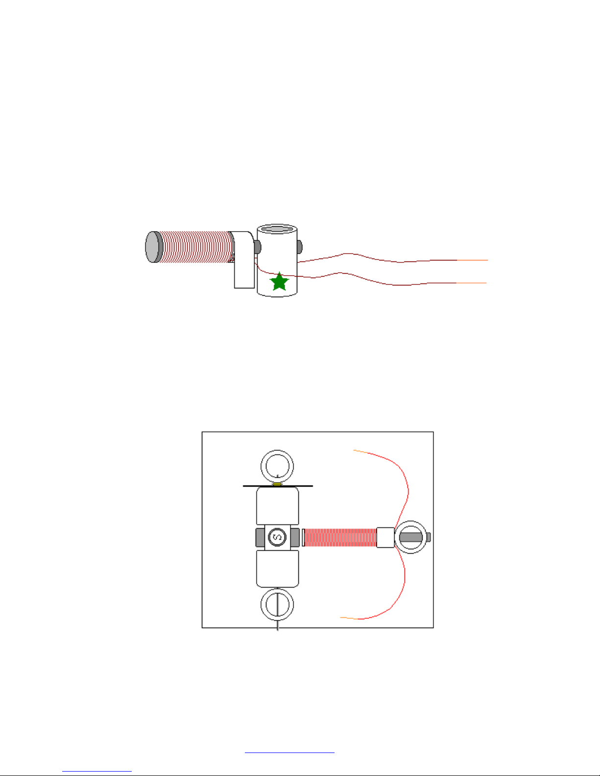
12.Cut two pieces of wire 9" (22-23 cm) long. Leave them for now - they will be used for
connecting the reed switch. All remaining wire on the spo ol should be used to wrap around
the area between the tape a nd the head of the nail.
o Tape one end of wire leaving about 6" (15 cm) open. You may use the tape that is
already on the nail.
o Wind all the wire in one rotational direction (either clockwise or counterclockwise)
moving back and forth along t he nail. Try to be as accurate as possible. Do not let
the wire slide off the end of the electromagnet.
o Tape the second end of the wire using the same tape. Both open ends of wire should
be about 6" (15 cm) long.
o Clean about 3/8" (10 mm) of the wire tips with fine sandpaper (included) or a sharp
knife to remove the insulation.
Test the electromagnet! Connect one wire to "+" and another wire to "-" of the battery. If
electromagnet is assembled correctly the head of the nail should attract metal objects such
as paper clips, small na ils, knife blade, etc.
13.Glue the electromagnet to the board as shown below. Turn the rotor slowly to see if the
magnets hit the electromagnet. If one or more do, move the electromagnet back until there
is a 1/16" (1.5 mm) gap between the electromagnet and the closest magnet on the rotor.
Assembly instructions for kit #9
All rights reserved. 2013 Simple Motors, LLC ♦ www.simplemotor.com ♦
5
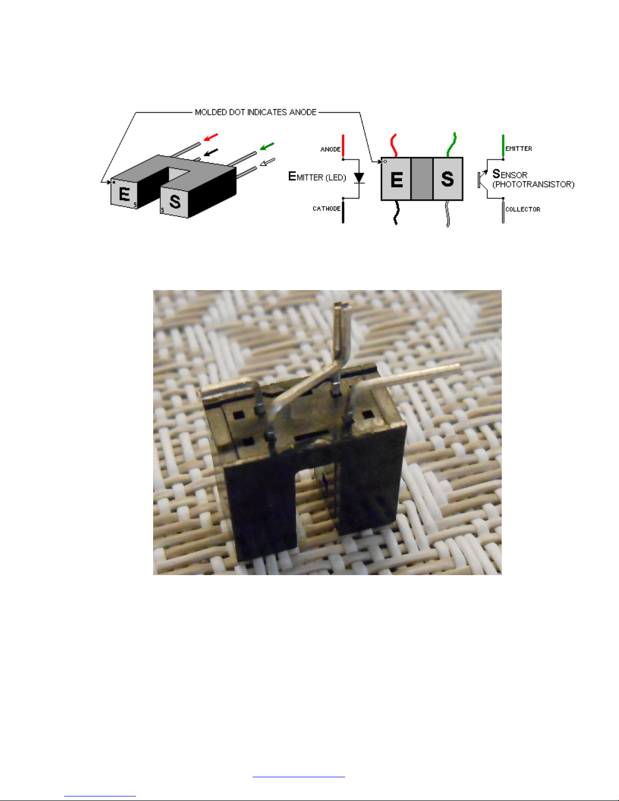
14.Locate the optointerrupter pins as shown on the following picture. It is very important to
identify all four pins properly. Wrong connection in the motor will destroy the
optointerrupter.
Bend and trim optointerrupter pins as shown below (view from non-branded side). Tweezers
or needle-nose pliers may be very helpful. You may use scissors for trimming.
Locate the 270 Ohm a nd 4.7 K (4700 Ohm) resistors. The 270 O hm resistor has red, violet,
brown and gold color bands. The 4.7 K resistor has yellow, violet, red and gold color bands.
Bend the leads of the resistors as shown below.
Solder these resistors together and to the optointerrupter as shown in the ne xt picture. See
the Links page at our web site for tips on soldering if you do not have enough experience in
this procedure.
IMPORTANT: D o not overheat the optointerrupter when you solder it. The solde ring iron
heat may destroy this sensitive device. If you were unable to attach the wire in 3 seconds,
let the optointerrupter cool off, and then try it again.
Assembly instructions for kit #9
All rights reserved. 2013 Simple Motors, LLC ♦ www.simplemotor.com ♦
6
 Loading...