

Page 1
SimpleComTools, LLC COM1000 – User Manual
User Manual
&
Command Reference Guide
SimpleComTools, LLC 1
May 2006
Page 2

SimpleComTools, LLC COM1000 – User Manual
Copyright © 2003-2006 SimpleComTools, LLC
All rights reserved. January 2006.
The information in this document is subject to change without notice. The statements, configurations,
technical data, and recommendations in this document are believed to be accurate and reliable, but are
presented without express or implied warranty. Users must take full responsibility for their applications of any
products specified in this document. The information in this document is proprietary to SimpleComTools, LLC.
Trademarks
SimpleComTools, the SimpleComTools logo, COM1000, and the COM1000 logo are trademarks of
SimpleComTools, LLC.
Statement of conditions
In the interest of improving internal design, operational function, and/or reliability, SimpleComTools, LLC
reserves the right to make changes to the products described in this document without notice.
SimpleComTools, LLC does not assume any liability that may occur due to the use or application of the
product(s) or circuit layout(s) described herein.
USA requirements only
Federal Communications Commission (FCC) Compliance Notice: Radio Frequency Notice
This device complies with Part 15 of the FCC Rules. Operation is subject to the following two conditions:
• This device may not cause harmful interference.
• This device must accept any interference received, including interference that may cause undesired operation.
Note: This equipment has been tested and found to comply with the limits for a Class B digital device,
pursuant to Part 15 of the FCC Rules. These limits are designed to provide reasonable protection against
harmful interference in a residential installation. This equipment generates, uses and can radiate radio
frequency energy and, if not installed and used in accordance with the instructions, may cause harmful
interference to radio communications. However, there is no guarantee that interference will not occur in a
particular installation. If this equipment does cause harmful interference to radio or television reception, which
can be determined by turning the equipment off and on, the user is encouraged to try to correct the
interference by one or more of the following measures:
• Reorient or relocate the receiving antenna.
• Increase the separation between the equipment and receiver.
• Connect the equipment into an outlet on a circuit different from that to which the receiver is connected.
• Consult the dealer or an experienced radio/TV technician for help.
European requirements only
EN 55 022 statement
This is to certify that the SimpleComTools COM1000 is shielded against the generation of radio interference
in accordance with the application of Council Directive 89/336/EEC, Article 4a. Conformity is declared by the
application of EN 55 022 Class B (CISPR 22).
Canada requirements only
Canadian Department of Communications Radio Interference Regulations
This digital apparatus does not exceed the Class B limits for radio-noise emissions from digital apparatus as
set out in the Radio Interference Regulations of the Canadian Department of Communications.
Règlement sur le brouillage radioélectrique du ministère des Communications
Cet appareil numérique respecte les limites de bruits radioélectriques visant les appareils numériques de
classe B prescrites dans le Règlement sur le brouillage radioélectrique du ministère des Communications du
Canada.
SimpleComTools, LLC 2
Page 3

SimpleComTools, LLC COM1000 – User Manual
Preface
The COM1000 is part of the SimpleComTools Industrial Internet Appliance family. The COM1000 supports
secure, reliable serial and IP communications and Internet Messaging applications in a single, integrated
hardware device. In this guide, the COM1000 may also be referred to as ‘the device’.
This guide provides instructions on how to install the COM1000, and how to install and replace other devices
that may interface with the various inputs or interfaces available in the COM1000. This guide also includes
technical specifications.
Before you begin
This guide is intended for qualified service personnel who are installing the COM1000 for the first time or who
need to install a switch, gauge, modem, or other device to an existing COM1000. However, before you install
anything related to the COM1000, make sure that the proper cables have been selected and/or the required
network cabling has been installed using standard cable system p ra ctice s.
Acronyms
This guide uses the following acronyms:
CTS clear to send
DCD data carrier detect
DCE data communications equipment
DSR data set ready
DTE data terminal equipment
DTR data terminal ready
GND ground
IP Internet Protocol
LAN local area network
LED light emitting diode
MAC media access control
NC normally closed
NO normally open
PPP point-to-point protocol
PSTN public switched telephone network
RTS ready to send
RX receive data
TX transmit data
URL uniform resource locator
VPN virtual private network
WAN wide area network
SimpleComTools, LLC 3
Page 4
SimpleComTools, LLC COM1000 – User Manual
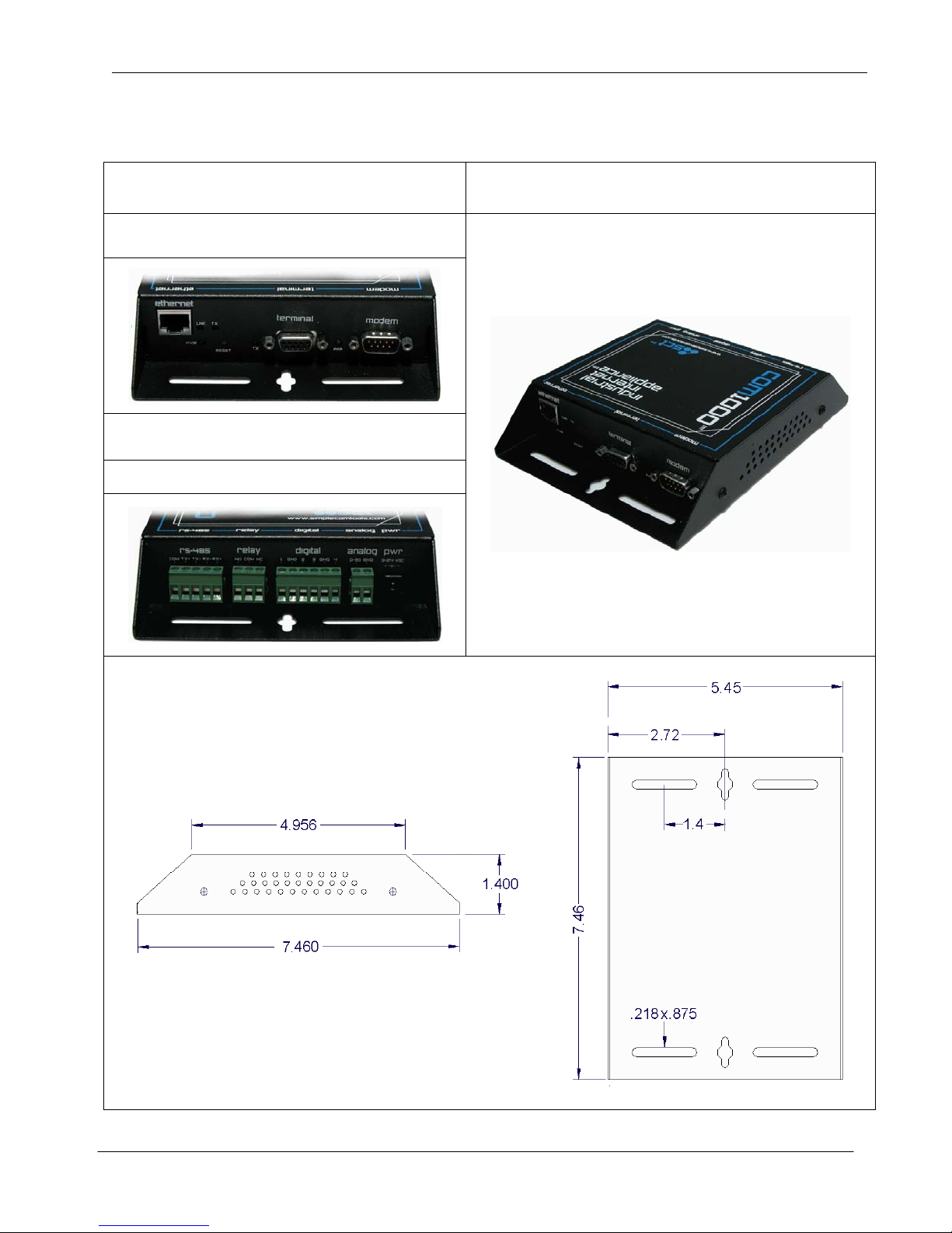
Hardware Overview
Front Side Top Side
(‘Front’ = Side that has Ethernet and Serial Interfaces)
Back Side
(‘Back’ = Side that has Terminal Strips and Power
Input)
SimpleComTools, LLC 4
Page 5
SimpleComTools, LLC COM1000 – User Manual
Front Panel LEDs
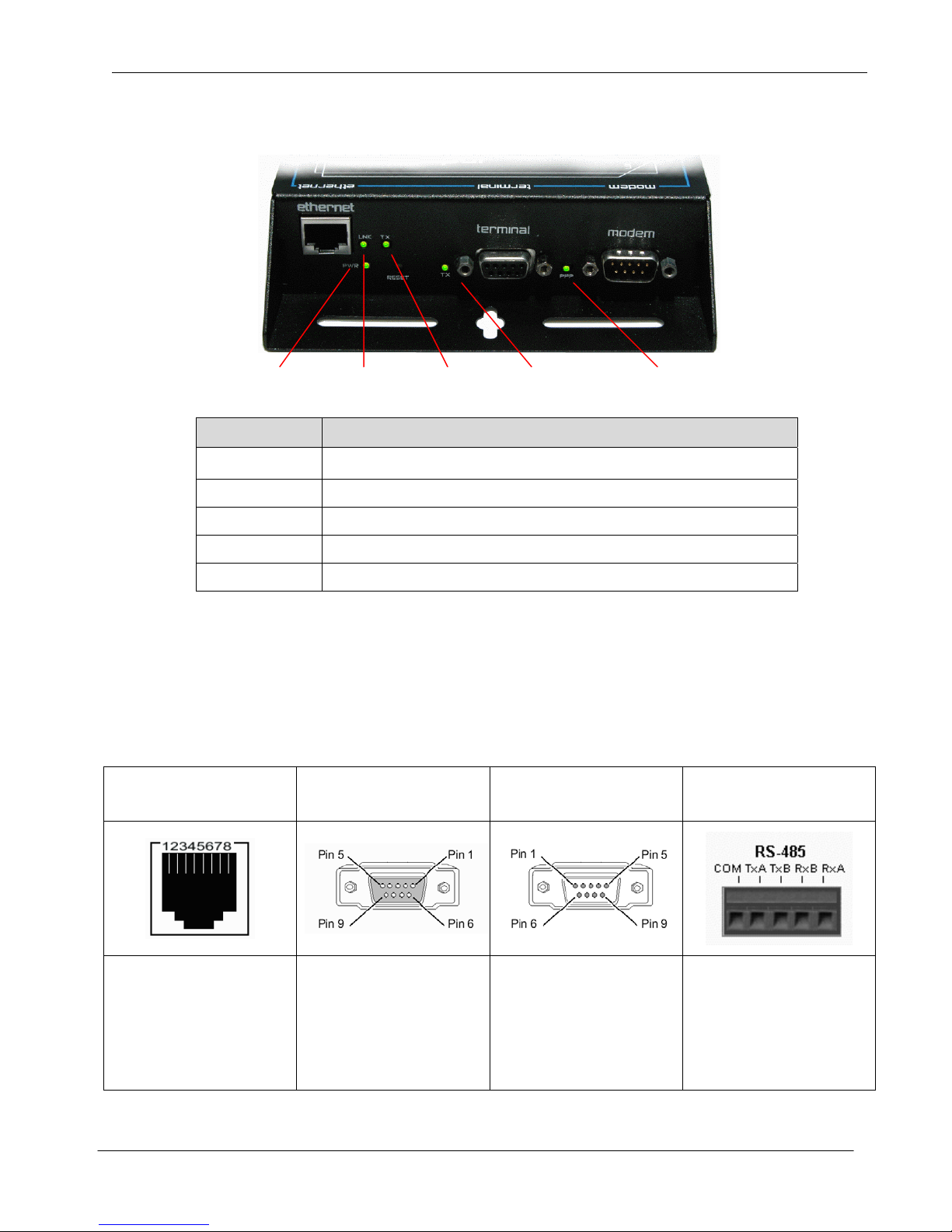
The front side of the COM1000 has (5) LEDs that indicate the status of the unit.
Power Ethernet Link Ethernet Tx Serial Tx PPP Connection
LED Description
Power
Ethernet LNK
Ethernet TX
Serial TX
PPP
Unit is currently powered on.
Unit is currently connected to an Ethernet network or device.
Unit is currently transmitting Ethernet traffic
Unit is currently communicating with a serial device on the Terminal Port
Unit is currently engaged in an active PPP session on the Modem Port
Communication interfaces
The COM1000 provides the following communication interfaces:
• One 10 BASE-TX Ethernet interface
• One RS232 Serial Terminal Port
• One RS232 Serial Modem Port
• One RS485 Port
Ethernet Port
(10 Base TX)
Female DB9
RS232 DCE Port
(Terminal Port)
RS232 DTE Port
(Modem Port)
Male DB9
RS485
This port is used to connect
to an LAN HUB or Switch.
To connect to LANs, use a
regular Ethernet cable. To
connect direct to a PC, you
will need a crossover cable.
This port is used to connect
to a computer or terminal
To connect a PC, you will
need a regular serial cable.
To connect a DCE, you will
need to use a null adapter.
SimpleComTools, LLC 5
This port is used to connect
to a modem or DCE.
To connect a modem, you
will need a regular serial
cable. To connect a PC, you
will need a null adapter.
Located on the BACK side,
this port is for RS485 only.
Supports 2 or 4-wire master
or slave connections.
Wiring requirements differ
based upon device network.
Page 6
SimpleComTools, LLC COM1000 – User Manual
Hardware interfaces
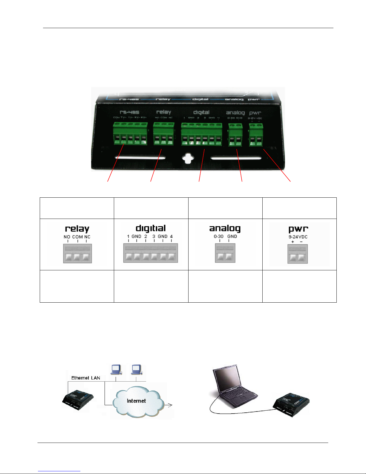
The COM1000 provides the following hardware interfaces:
• One Analog Input
• Four Digital Inputs
• One Relay Input
RS-485 Port Relay (4) Digital Inputs (1) Analog Input DC Power
Relay Outputs Digital Inputs Analog Inputs
This interface is used to
connect a device that you
want to turn on and off.
This interface is used to
connect simple contact
closure switches.
This interface is used to
connect simple analog
measurement gauges.
Power Input
This interface is used
to connect to a 9-30 VDC
power source.
LAN interface connections
The 10 BASE-TX connection is used for connections to any Ethernet LAN. This type of installation requires
the use of Category 5 twisted-pair wire. The 10BASE-TX interface complies with the EIA 568 wiring standard.
Sample Ethernet Connections
COM1000 connected to an Ethernet LAN COM1000 connected to a PC using a crossover cable
SimpleComTools, LLC 6
Page 7
SimpleComTools, LLC COM1000 – User Manual
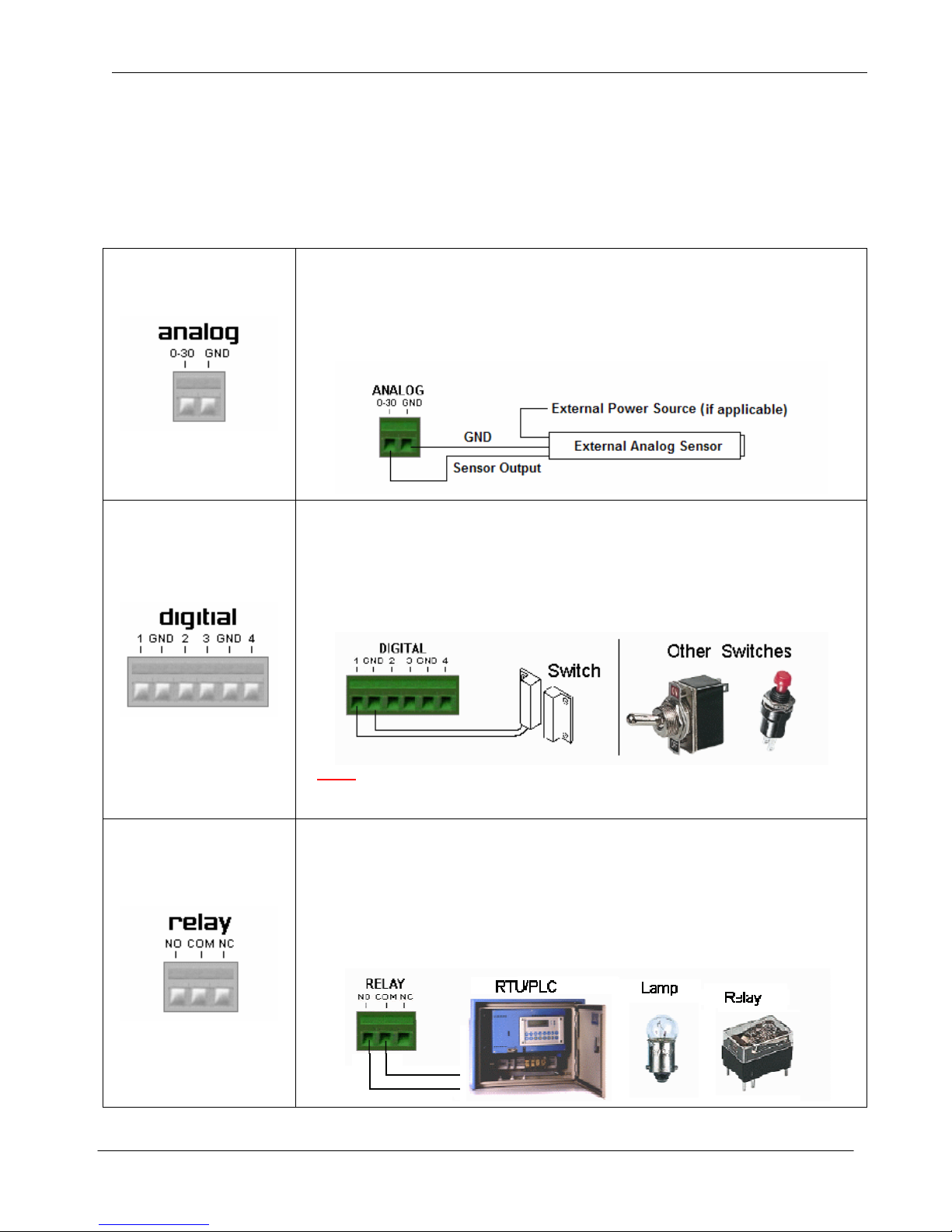
Connecting Sensors, Switches, or Devices
The COM1000 provides the following hardware interfaces:
• One Analog Input
• Four Digital Inputs
The following describes how to wire sensors, switches or controls to these inputs.
• One Relay Input
The ANALOG interface has the ability to accept any sensor with a DC voltage
output ranging between 0 and 30 volts. (Examples of acceptable sensor ranges
would include 1-5, 0-10, 0-12, 0-30, etc). The analog interface has two inputs;
the leftmost input (labeled 0-30) is where you place the sensor’s POSITIVE or
OUTPUT line. The rightmost input (labeled GND) is where you connect the
sensor’s ground wire.
The DIGITAL interface is designed to connect up to (4) dry contact closures.
The interface provides (6) wire inputs; (4) switch inputs and (2) grounds (GND).
Switches are connected across any of the inputs (labeled with numbers 1,2,3,4).
The grounds (labeled with GND) are used as commons, and are where you
connect the second switch wire. The reasons for only (2) commons is because
you can share the GND inputs between switches 1 and 2 or switches 3 and 4.
The following is a wiring example:
NOTE:
The digital inputs are self powered and require dry contact closures.
Applying voltage to the inputs may result in permanent damage to the unit.
The RELAY is designed to switch currents (120VAC/1A, 24VDC/2A).
In a sense, the RELAY can act as a contact closure or switch for any external
device. It can be used to trigger another device with a digital input, or even
another relay. The relay connections are labeled as Normally Open (NO),
Common (COM), and Normally Closed (NC). When wiring, connect your wires
to the NO and COM if you want the switched circuit to be CLOSED when the
relay is ACTIVATED. Connect your wires to NC and COM if you want the
switched circuit to be OPEN when the relay is ACTIVATED.
SimpleComTools, LLC 7
Page 8
SimpleComTools, LLC COM1000 – User Manual
Installation Requirements and Instructions
Mounting: The COM1000 has (4) slotted mounting holes and (2) oval mounting holes for easy
mounting and installation. You can use either wood or sheet metal screens, hooks, or
other common fasteners to mount or hang the device.
The (4) slotted mounting holes and (2) oval mounting holes may be mounted to sheet
metal, wood, or plastic. Simply place or hang the COM1000 on a flat surface and
insert your fastener of choice through any of these base-mounting holes.
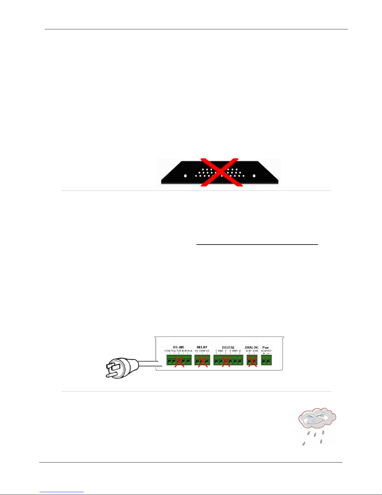
Do NOT insert any fasteners, string, wire, line, or rope into the holes on the sides of
the COM1000, as this may damage internal electrical components.
Power: The COM1000 comes equipped with a 110-12VDC-power adapter. However, for
direct wire requirements, the COM1000 will accept 9-30VDC. The power interface is
a standard 2-wire (+ and -) terminal strip.
Disconnect the 2-lead terminal strip insert plug from the Com1000 power interface.
With a power adapter or wire that is not yet connected to a power supply
positive wire into the left (+) side access hole of the insert plug and tighten the
retaining screw. Next, insert the ground wire into the right (-) side access hole of the
terminal strip and tighten the second retaining screw. Plug the terminal strip plug into
the COM1000 power interface. Finally, connect the other end of the wire or the power
supply to your power source. The PWR light on the front of the COM1000 should now
be lit. If it is not, check the power source to make sure it is connected or turned on.
You may also want to check the make sure the (+) and (-) leads are wired correctly.
Do NOT insert live power leads directly into the Analog, Digital, Relay or RS-485
inputs, as this may severely damage the COM1000. Failure to comply with this
warning will void any and all existing product warranties or service agreements.
, insert the
Environment: The COM1000 is NOT waterproof or weatherproof.
Installation should include an enclosure to protect electronics.
Preferably a NMEA-4 type enclosure to ensure protection from
water and humidity.
SimpleComTools, LLC 8
Page 9
SimpleComTools, LLC COM1000 – User Manual
RS485 Configuration and Wiring
The COM1000 RS485 port is an unaddressed transparent interface designed to support any RS-485
equipment. It supports both Full and Half-Duplex communications, so it can be used to interface a single
device or a multi-drop network of devices.
Applications
The COM1000 RS485-port can be configured to perform a number of applications, including acting as a UDP
or TCP device server or client, data redirecting via SMTP or FTP, and data arrival event logging. The choice
of applications is detailed in the COM1000 Configuration Utility section under the RS485 tab.
TCP/UDP Servers
The most common use for the RS485 port is as a TCP or UDP
device server. In this application, the COM1000 provides the
ability to reach RS485 connected devices or device networks
from any remote IP host via a standard RAW TCP or UDP
socket. Since the COM1000 is a transparent IP to serial
bridge, there are no limitations on the data protocol. Any ASCII
or Binary protocol will be passed seamlessly to the end device.
Communication Drivers
The COM1000 IP-to-serial application is a raw socket connection. Therefore there are no driver requirements
to establish your connection. As long as your host-end application has the ability to encapsulate the ASCII or
Binary data stream into a TCP or UDP packet, you will be able to make the connection. If you host end
application does not have that ability, you may need to employ the use of a serial to IP COM Port Redirector.
The purpose of the redirector is to make the virtual COM port exhibit behavior that closely resembles that of a
"real" COM port, i.e., a COM port driver for local serial port hardware. A virtual COM port itself is a relatively
simple software mechanism that can be implemented by driver software similar to that of a conventional COM
port driver. The redirector will typically permit creation of many (at least 256) virtual COM ports, and provide
the ability to assign or bind a remote IP address of a device server to that virtual port. This, in order to reach a
remote device, the host application simply opens the virtual com port associated with that remote device and
the connection is automatically established.
There are a number of such applications on the market, available from companies such as Serial/IP from
Tactical Software (www.tacticalsoftware.com
HW Group (www.hwgroup.cz
that provide Virtual Com Port to UDP redirection only (www.simplecomtools.com/virtualcomudp.html
Port Configuration
The COM1000 is capable of supporting a variety of baud rate options, ranging from 1200 – 115200kbps.
In addition, the 485 interface supports both full-duplex and half-duplex installations. By default, the COM1000
is setup in Half-duplex mode. In order to support full-duplex, the RS485 Mode register needs to be set.
(RS485Mode=1). See the RS485 command list for more details on configuring the 485 port o ptions.
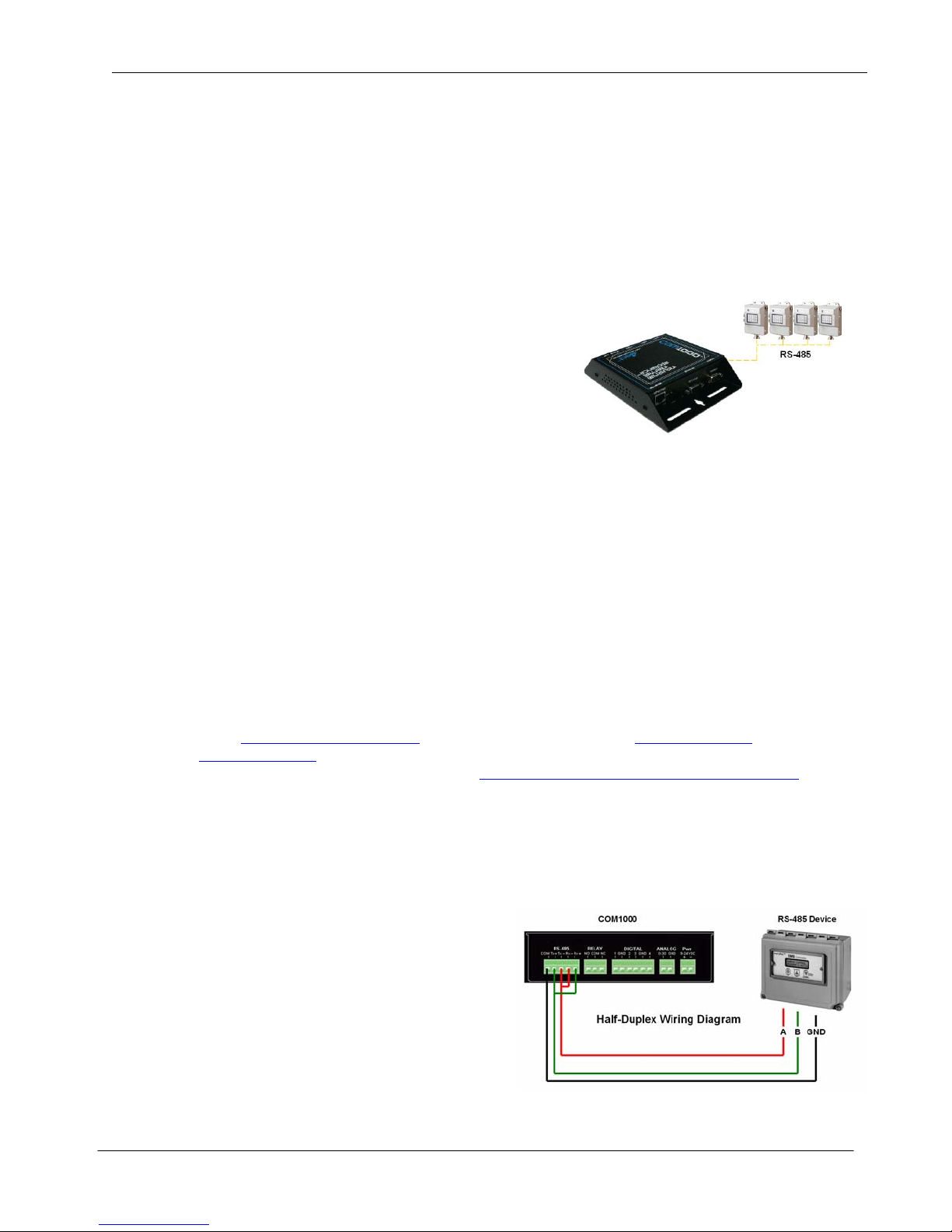
Wiring
The COM1000 RS485 interface has 5 terminals:
COMMON (GND), TX+/TX- and RX+ and RX-. When
used in full-duplex mode, wiring should follow the
specifications set forth by the equipment vendor. The
RS485mode selection needs to be set to (1).
When used in half-duplex mode, the COM1000 will need
to have the TX+/RX+ and TX-/RX- terminals jumpered
as show in the diagram at right.
). Simple Com Tools also offers a similar application called Virtual-COM UDP
), TCP-COM from TalTech (www.taltech.com) and VSP from
)
SimpleComTools, LLC 9
Page 10

SimpleComTools, LLC COM1000 – User Manual
COM1000
Configuration
Utility
SimpleComTools, LLC 10
Page 11
SimpleComTools, LLC COM1000 – User Manual
COM1000 Setup and Configuration
To make setup and configuration easy, the COM1000 comes with a MS Windows based Configuration Utility.
This makes getting the device up and running quick and easy..
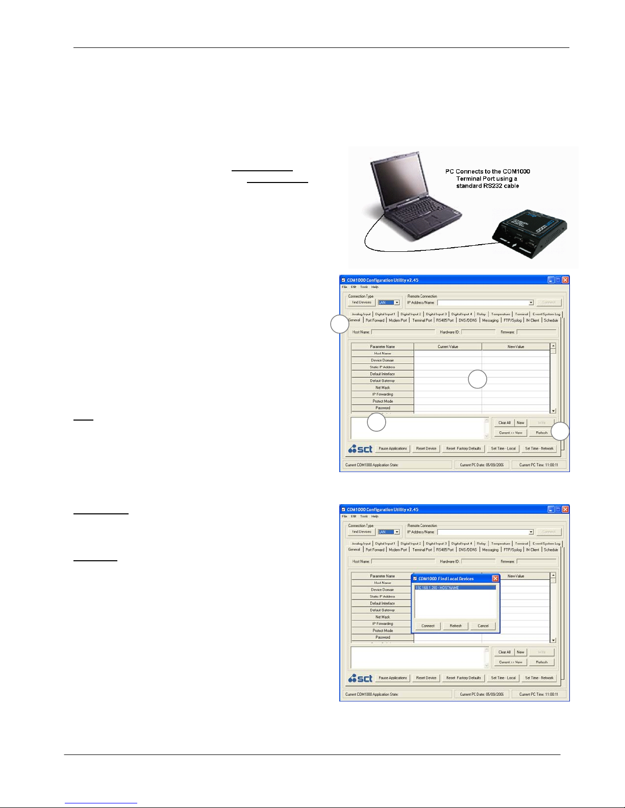
Connection Steps
Step 1:
Connect your PC to the COM1000 Terminal Port
any standard RS232 serial cable. The Terminal Port is a
DCE, so there is no need for a null adapter. Any standard
serial cable will work just fine .
You may also choose to connect the COM1000 to an
Ethernet hub or directly to an Ethernet card via a
crossover cable.
Step 2:
Launch the COM1000 Configuration Utility. You will see
that the applications is divided into (4) sections:
1. Locating/Connecting Devices
2. Viewing/Editing Settings
3. Setting Notes
4. Setting Controls
Step 3:
Locate the device you wan to configure by selecting the
desired method of communication.
LAN
Any COM1000 located on your Local Area Network can
be found using this utility. Select LAN, enter the device
Password, and click on the Find Devices button. You
will see a popup box display the names of the devices
found on the local network. Highlight the device you wish
to configure, and select Connect.
COM PORT
Selected a COM PORT, click Find Devices and select
your device from the popup box.
REMOTE
Select REMOTE, enter the device password, enter the
IP Address or Domain Name, and select Connect. This
feature can also be used to make a direct connection to
a device where the IP or name is known.
Step 4:
Once connected to your device, you will see a splash
screen, and the application will load all the parameters
for the device for display.
Clicking on any of the Parameters Names. This will
display details for that parameter in the Notes box.
using
1
2
3
4
SimpleComTools, LLC 11
Page 12
SimpleComTools, LLC COM1000 – User Manual
Configuration Utility Basics
Making changes
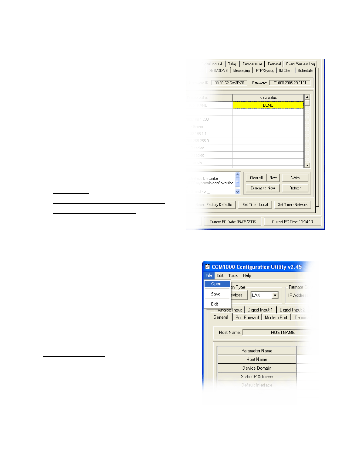
Making changes to the device is done by
entering the change in the New Value side.
Changes can be entered use text or by
selecting items from the drop-down menu.
Hit ENTER when entering the new value.
Unwritten changes are shown in Yellow.
Writing changes
The bottom buttons make it easy to navigate.
Here are the basic button functions:
• WRITE sends all changes to the device.
• REFRESH updates the current display.
• CLEAR NEW clears the New Value area.
• RESET DEVICE will restart the COM1000.
• RESET FACTORY DEFAULTS will return
the device to its original factory defaults
Using Templates
In order to save a device configuration for future use
or to make copies of a working device, the configuration
utility provides a TEMPLATE function.
Here are the basic options:
Saving a configuration
1. Select the Current >> New button to copy the
current configuration to the New Value side.
2. Select the File/Template/Save and give the file
a name and save it with a .tpl extension.
Opening a configuration
1. Select File/Template/Open and select the
configuration file you want to use. When opened,
the settings will populate the New Value side.
2. Edit values if appropriate.
3. Select WRITE to send changes to the device.
SimpleComTools, LLC 12
Page 13
SimpleComTools, LLC COM1000 – User Manual
Configuration Utility Register Descriptions
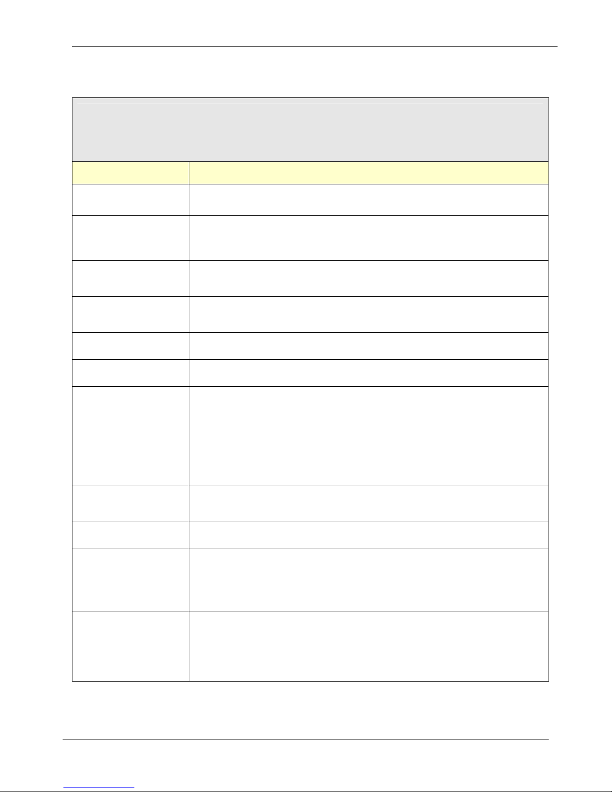
GENERAL
The General tab is for configuring parameters related to the general operation of the device. This is where you begin
to configure a device name, network settings, and security. This is also where you configure the ho w data files will
be saved, how packets will be formatted, and whether you will want to have the device DEBUG turned o n or not.
Parameter Name Description
Hostname
Device Domain
Static IP Address
Default Interface
Default Gateway IP address of the router that forwards traffic to a destination outside of the subnet.
Net Mask IP address subnet mask used to determine what subnet an IP address belongs.
IP Forwarding
Protect Mode
Name used as Internet HOST and NETBIOS NAME for MS Windows Networks.
Accepts up to 50 alphanumeric characters.
Name consists of a sequence of two or more groups of characters separated by periods
and includes the top-level, 2nd, or 3rd level domain names.
Examples: 'mydomain.com' or 'east.mydomain.com'.
Static IP address to be assigned to the Ethernet interface. This is the address to be
used every time the device is powered up. DEFAULT ADDRESS = 192.168.1.200
This is the default interface to be used by the device for sending data.
Options: 0 = Ethernet (DEFAULT)
1 = Modem
This value is used to enable forwarding of IP packets between the Ethernet and serial
(PPP) interfaces. Forwarding is only provided from the 'PRIVATE' Ethernet IP address
to a 'PRIVATE' serial (PPP) IP address. Forwarding packets to and from a public
(Internet) link requires a modem or ISP to provide Network Address Translation (NAT).
Options: 0 = Disabled (DEFAULT)
1 = Enabled
NOTE: Consult the IP Forwarding addendum for specific information on how to
configure the Ethernet and PPP interface addresses for IP Forwarding.
Protected Mode restricts access to the device.
Options: 0 = Disabled (DEFAULT)
1 = Enabled
Password Sets the device password. DEFAULT is ‘simple’.
Character used to separate the data elements in text files.
Options: 0 = space (DEFAULT)
Output Delimiter
Packet Format
1 = comma (,)
2 = semicolon (;)
3 = colon (:)
Select a packet format for UDP/TCP application messages.
Options: 0 = Data Only (DEFAULT)
1 = Message Only
2 = HostName, Data
3 = HostName, Date/Time, Data
4 = HostName, Date/Time, Message, Data
SimpleComTools, LLC 13
Page 14

SimpleComTools, LLC COM1000 – User Manual
Configures interface values to be displayed by the 'STATUS' command.
This includes Analog Input, Digital Inputs, Relay State, and Modem status. Multiple
values are separated by commas; ie 1,2,3,4,5,6)
Example: 'AT*STATUSFORMAT=2,3,4,5' would dis play the state of all 4 Digital Inputs.
Options: Options: 0 = None (DEFAULT)
1 = Host Name
2 = Date & Time
3 = Digital Input 1 State
4 = Digital Input 2 State
5 = Digital Input 3 State
6 = Digital Input 4 State
Status Format
7 = Digital Input 1 Count
8 = Digital Input 2 Count
9 = Digital Input 3 Count
10 = Digital Input 4 Count
11 = Analog Input Value
12 = Temperature Value (Celsius/Fahrenheit)
13 = Relay State
14 = Relay Control Button
15 = Ethernet and PPP Address
NOTE:
Order of values can be in any order you wish.
Web Server Enabled - Turn on or off the device web server
Web Server
Web Server Port
PING IP Address
PING Retires
PING Timer
Time Sets the device date. Use the format MM/DD/YYYY.
Options: 0 = Disabled (DEFAULT)
1 = Enabled
Set Web Server Port
nnnnn = (5 digit value with range between 1 and 65535). (Default value = 80)
Destination IP Address of a remote Destination IP or Domain where the COM1000 will
send a PING in order to test for network connectivity. Accepts numeric IP Address or
fully qualified domain name (abc.123.com). (Accepts up to 50 characters).
Default = 206.124.64.253
Number of times to PING the remote destination IP or Domain during a PING attempt.
This number should be tuned to guarantee at least one PING success during an event.
(5 digit value with range between 0 and 65535)
Number of minutes to wait between PING attempts.
Options: 0 = No PINGS will be sent (DEFAULT)
1-65535 = number of minutes between attempts (60 = one attempt per hr)
NOTE: A PING attempt is the entire number of PING retries. Not just a single PING.
Date Sets the device time. Use the format HH:MM:SS.
SNTP Server IP or Domain of Simple Network Time Protocol (SNTP) server.
SimpleComTools, LLC 14
Page 15

SimpleComTools, LLC COM1000 – User Manual
Sets the update interval for real-time clock updates from SNTP server.
SNTP Update Interval
Time Zone
Daylight Savings Time
Options: 0 = not active (DEFAULT)
1-8760 = number of hours between updates
Sets the time zone where the device will be located.
Enter integer value between -12 and +13 to indicate the offset from Greenwich Mean
Time (GMT).
Sample values are as follows:
-12:00 = GMT-12 – Eniwetok
-11:00 = GMT-11 – Samoa
-10:00 = GMT-10 – Hawaii
-09:00 = GMT- 9 – Alaska
-08:00 = GMT- 8 – US Pacific Time
-07:00 = GMT- 7 – US Mountain Time
-06:00 = GMT- 6 – US Central Time
-05:00 = GMT- 5 – US Eastern Time
-04:00 = GMT- 4 – Atlantic Time
-03:00 = GMT- 3 – Greenland
-02:00 = GMT- 2 – Mid-Atlantic
-01:00 = GMT- 1 – Azores
00:00 = GMT – Greenwich Mean Time
Daylight savings time enabled:
Options: 0 = not enabled (DEFAULT)
1 = US Standard Enabled (Change Time at 0200 Hours)
2 = EU Standard Enabled (Change Time at 0100 Hours GMT)
+01:00 = GMT+ 1 – Berlin, Rome, Paris
+02:00 = GMT+ 2 – Jerusalem, Helsinki
+03:00 = GMT+ 3 – Moscow, Nairobi
+04:00 = GMT+ 4 – Abu Dhabi
+05:00 = GMT+ 5 – Karachi
+06:00 = GMT+ 6 – Astana
+07:00 = GMT+ 7 – Bangkok
+08:00 = GMT+ 8 – Hong Kong, Singapore
+09:00 = GMT+ 9 – Tokyo
+10:00 = GMT+10 – Guam
+11:00 = GMT+11 – New Caledonia
+12:00 = GMT+12 – Fiji
+13:00 = GMT+13 – Nuku’alofa
SimpleComTools, LLC 15
Page 16
SimpleComTools, LLC COM1000 – User Manual
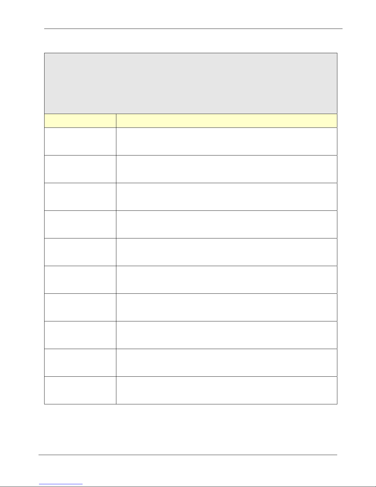
PORT FORWARDING
Port Forwarding allows you to route specific types of inbound application packets coming in over the PPP interface to
specific IPs on the LAN side of the device. Enter the expected port number, or range of ports, and the LAN IP
address where those packets need to be forwarded. For one specific port number, enter the same port number twice.
Examples for the use of this feature may include a web server on Port 80 or FTP server on Port 21, etc. Entries will
include both TCP and UDP. There is no support for individual packets types.
Parameter Name Description
Application Port Forwarding Rule #1. Allows you to route specific types of inbound
Application Port 1
Application Port 2
Application Port 3
application packets coming in over the PPP interface to specific IPs on the LAN.
Enter the expected port number, or range of ports, and the desired LAN IP address.
Application Port Forwarding Rule #2. Allows you to route specific types of inbound
application packets coming in over the PPP interface to specific IPs on the LAN.
Enter the expected port number, or range of ports, and the desired LAN IP address.
Application Port Forwarding Rule #3. Allows you to route specific types of inbound
application packets coming in over the PPP interface to specific IPs on the LAN.
Enter the expected port number, or range of ports, and the desired LAN IP address.
Application Port 4
Application Port 5
Application Port 6
Application Port 7
Application Port 8
Application Port 9
Application Port 10
Application Port Forwarding Rule #4. Allows you to route specific types of inbound
application packets coming in over the PPP interface to specific IPs on the LAN.
Enter the expected port number, or range of ports, and the desired LAN IP address.
Application Port Forwarding Rule #5. Allows you to route specific types of inbound
application packets coming in over the PPP interface to specific IPs on the LAN.
Enter the expected port number, or range of ports, and the desired LAN IP address.
Application Port Forwarding Rule #6. Allows you to route specific types of inbound
application packets coming in over the PPP interface to specific IPs on the LAN.
Enter the expected port number, or range of ports, and the desired LAN IP address.
Application Port Forwarding Rule #7. Allows you to route specific types of inbound
application packets coming in over the PPP interface to specific IPs on the LAN.
Enter the expected port number, or range of ports, and the desired LAN IP address.
Application Port Forwarding Rule #8. Allows you to route specific types of inbound
application packets coming in over the PPP interface to specific IPs on the LAN.
Enter the expected port number, or range of ports, and the desired LAN IP address.
Application Port Forwarding Rule #9. Allows you to route specific types of inbound
application packets coming in over the PPP interface to specific IPs on the LAN.
Enter the expected port number, or range of ports, and the desired LAN IP address.
Application Port Forwarding Rule #10. Allows you to route specific types of inbound
application packets coming in over the PPP interface to specific IPs on the LAN.
Enter the expected port number, or range of ports, and the desired LAN IP address.
SimpleComTools, LLC 16
Page 17
SimpleComTools, LLC COM1000 – User Manual
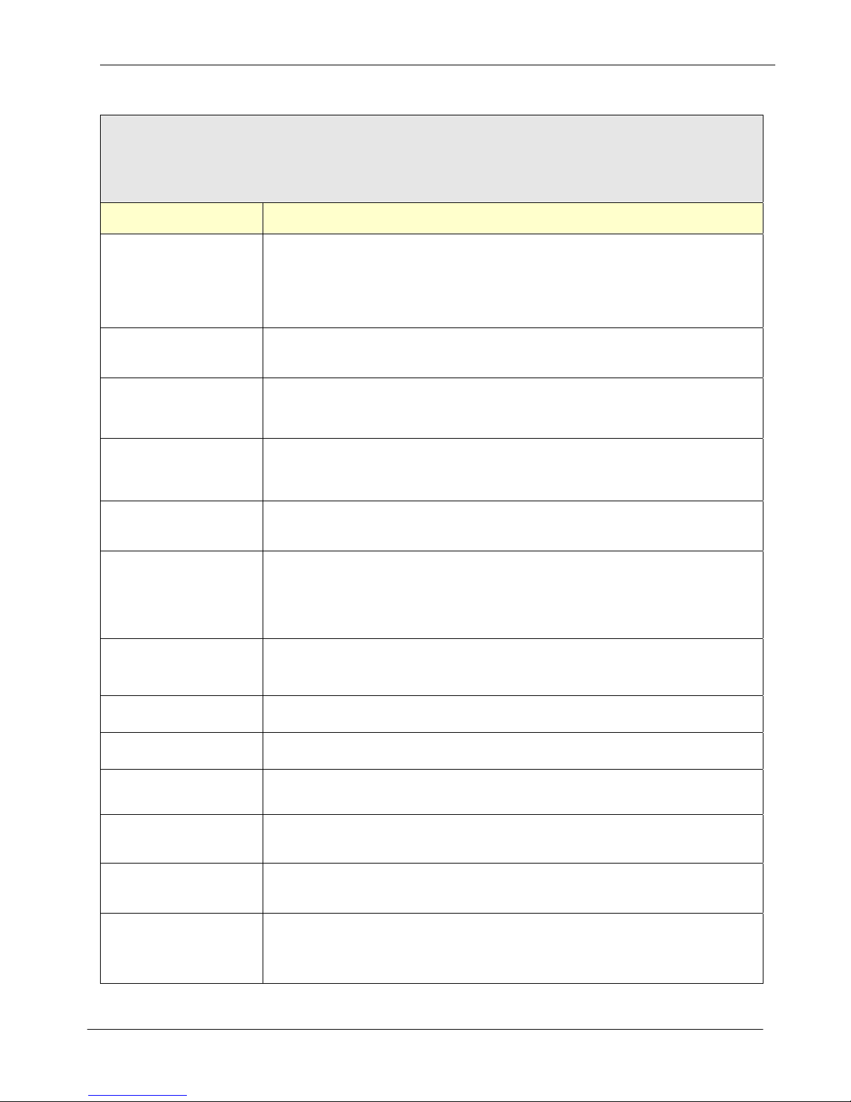
MODEM PORT
The Modem Port tab is for configuring parameters related to the Modem (DTE) Port. This is where you begin to
configure a device to work with a landline or wireless modem. You will setup parameters such as initialization string,
dial string, hangup string, signal control, mode connection options.
Parameter Name Description
Sets Modem Port Baud Rate, Data Bits, Parity and Stop Bits.
Example: 19200,8N1 (DEFAULT = 115200,8N1)
Port Settings
DCD Control
DTR Control
Flow Control
Local Echo
Baud Rate Options: 1200, 2400, 4800, 9600, 18200, 38400, 57600, 115200
Data Bits Options: 7 or 8 Data Bits
Parity Options: None, Even, Odd
Stop Bit Options: 1 or 2 Stop Bits
Sets how the COM1000 uses the DCD signal from the modem.
Options: 0 = Ignore DCD (Send data regardless of DCD state) (DEFAULT)
1 = Use DCD (Look for DCD before dialing or sending data)
Sets how the COM1000 uses the DTR to control the modem.
Options: 0 = Disable DTR (Do not assert DTR at any time)
1 = Assert DTR for connection control (DEFAULT)
2 = Always assert DTR regardless of modem state
Sets how the COM1000 uses Flow Control.
Options: 0 = Disable Flow Control
1 = Hardware Flow Control (DEFAULT)
2 = Xon/Xoff
Echo typed characters back locally.
Options: 0 = Echo Off
1 = Echo On (DEFAULT)
Modem Mode of Operation
Options: 0 = Never Connect
Modem Mode
Modem Mode Timer
Modem Setup String Sets modem setup string. Accepts alpha numeric value up to 50 characters
Modem Init String Sets modem initialization string. Accepts alphanumeric value up to 20 characters.
Modem Dial String
Modem Escape String
Modem Hangup String
Line Termination
Character
1 = Dial on Demand (DEFAULT)
2 = Always maintain connection
3 = PPP Server
Modem Connection Timer
Options: 0 = No specific time; hang up after transaction (DEFAULT)
1 – 65535 = (Timer in seconds)
Sets modem dial string. Accepts alphanumeric value up to 20 characters
Used for setting both dial prefix (ATD, ATDT, etc) and phone number.
Sets modem escape string. Used for setting the value required by the modem to
escape from a session. Accepts alphanumeric value up to 20 characters (+++)
Sets modem hangup string. Accepts alphanumeric value up to 20 characters
Used for setting the value required by the modem to hangup a session. (ATH)
Sets line termination sequence used when sending command strings to a modem.
Options: 0 = CR (Send a Carriage Return after sending string) (DEFAULT)
1 = LF (Send a Line Feed after sending string)
2 = CR+LF (Send a Carriage Return + Line Feed after sending string)
SimpleComTools, LLC 17
Page 18

SimpleComTools, LLC COM1000 – User Manual
Username
Password
PPP Server (Peer) IP
PPP Client IP
Dialup or PPP Account Username. (Accepts up to 50 characters).
Example: jonhdoe
Dialup or PPP Account Password. (Accepts up to 50 characters).
Example: password123
PPP SERVER IP. The IP Address that COM1000 will use as it’s internal address when
used as Remote Access/PPP Server. Accepts numeric IP Address only.
PPP CLIENT IP: The IP Address that COM1000 will assign to the user or machine
making a dial-in/PPP connection to the PPP Server. Accepts numeric IP Address only.
SimpleComTools, LLC 18
Page 19
SimpleComTools, LLC COM1000 – User Manual
TERMINAL PORT
The Terminal Port tab is for configuring parameters related to the Terminal (DCE) Port. This is where you begin to
configure a device to work with a PC, data terminal, RTU, PLC, or data logger. You will setup parameters such as
port speed, signal control, application options, etc.
Parameter Name Description
Sets Terminal Port Baud Rate, Data Bits, Parity and Stop Bits.
Example: 19200,8N1 (DEFAULT = 115200,8N1)
Port Settings
DCD Control
Baud Rate Options: 1200, 2400, 4800, 9600, 18200, 38400, 57600, 115200
Data Bits Options: 7 or 8 Data Bits
Parity Options: None, Even, Odd
Stop Bit Options: 1 or 2 Stop Bits
Sets how the COM1000 uses DCD to control the Terminal.
Options: 0 = Always assert DCD (DEFAULT)
1 = DCD used for connection control
- active when IP network is available
- inactive when network connection drops
DTR Control
DSR Control
Local Echo
Quiet Mode
Sets how the COM1000 responds to DTR from the Terminal.
Options: 0 = Ignore DTR transitions (DEFAULT)
1 = Respond to DTR transitions, leave modem connected
2 = Respond to DTR transitions, reset modem
3 = Respond to DTR transitions, reset device, return to start mode
Sets how the COM1000 uses DCD to control the Terminal.
Sets how the COM1000 uses DSR to control the Terminal.
Options: 0 = Always assert DSR and accept data regardless of DTR status
1 = DSR used for connection control (DEFAULT)
- active when IP network is available
- inactive when network connection drops
Echo typed characters back locally.
Options: 0 = Echo Off
1 = Echo On (DEFAULT)
NOTE:
Typed characters will only be echoed when terminal port is NOT engaged in an
application. Once port is configured for TAPP1, TAPP2, TAPP3 or used as a UDP or
TCP device server, ECHO no longer functions. In order to communicate to the device,
you will need to reset/power-cycle the device. At that point you will have (20) seco nds
in which to communicate. In order to continue communications past that 20 second
period, you will need to PAUSE the device and stop it from engaging the applications.
This is done using the PAUSE APPLICATIONS button located at the at the bottom left
corner of the GENERAL tab.
Suppress status or command response output.
Options: 0 = Off (DEFAULT)
1 = On
Sets how the COM1000 uses Flow Control.
Flow Control
Options: 0 = Disable Flow Control
1 = Hardware Flow Control (DEFAULT)
2 = Xon/Xoff
SimpleComTools, LLC 19
Page 20

SimpleComTools, LLC COM1000 – User Manual
Sets the first of 3 applications to run on the Terminal Port. Enter the value representing
how you want the Terminal Port to handle incoming serial data.
Options:
0 = No Action
1 = Serial Stream UDP
(Sends incoming data to remote IP via UDP packet)
2 = Serial Stream TCP
(Sends incoming data to remote IP via TCP packet)
3 = Serial Stream SMTP
(Sends incoming data to remote user via SMTP message)
4 = Serial Stream SMS
(Sends incoming data to remote user via SMS message )
Application 1
5 = Serial Stream FTP
(Uploads incoming data to remote server via FTP)
6 = Serial Stream SYSLOG
(Uploads incoming data to remote server via Syslog Messages)
7 = Serial Stream Relay ON
(Open/energize relay when data comes in on terminal port)
8 = Serial Stream Relay OFF
(Close/de-energize rel ay when data comes in on terminal port)
9 = Serial Stream Logger
(Store data that comes in on terminal port)
10 = Serial Stream MPort
(Route data that comes in on terminal port directly to modem port)
11 = Serial Stream RS485
(Route data that comes in on terminal port directly to RS485 port)
Application 2
Application 3
Trigger 1
Trigger 2
Trigger 3
Sets the 2nd of 3 applications to run on the Terminal Port. Enter the value representing
how you want the Terminal Port to handle incoming serial data.
Options: Same as Application 1
Sets the 3rd of 3 applications to run on the Terminal Port. Enter the value representing
how you want the Terminal Port to handle incoming serial data.
Options: Same as Application 1
Sets the trigger that will initiate the Application #1 event.
Enter the value representing how you want the application to start.
Options:
0 = No Action
1 = Timer
(Send inbound data every 'n' minutes (*TTIMER1)
2 = Intercharacter Timer (ICT)
(Send inbound data after pause between characters (*TICT)
3 = Serial Stream Value
(Send data based on specif ic serial stream characters (*TSTREAM1)
4 = Buffer Limit
(Send data after reaching a specific data limit (*TBUFFER)
Sets the trigger that will initiate the Application #1 event.
Enter the value representing how you want the application to start.
Options: Same as Trigger 1
Sets the trigger that will initiate the Application #1 event.
Enter the value representing how you want the application to start.
Options: Same as Trigger 1
SimpleComTools, LLC 20
Page 21

SimpleComTools, LLC COM1000 – User Manual
Terminal Port Application #1 Timer Trigger. Value 'n' is in minutes. This is the period of
Elapsed Timer 1
Elapsed Timer 2
Elapsed Timer 3
Data Stream 1
Data Stream 2
time to wait before executing *TAPP1. This value requires that TERMINAL PORT APP
#1 TRIGGER be set to 1 (Timer).
Terminal Port Application #2 Timer Trigger. Value 'n' is in minutes. This is the period of
time to wait before executing *TAPP1. This value requires that TERMINAL PORT APP
#2 TRIGGER be set to 1 (Timer).
Terminal Port Application #3 Timer Trigger. Value 'n' is in minutes. This is the period of
time to wait before executing *TAPP1. This value requires that TERMINAL PORT APP
#3 TRIGGER be set to 1 (Timer).
Serial Data Stream used to trigger events (Up to 20 characters). This is the exact text
being filtered before executing any of the *TAPP selections. This value requires that
TERMINAL PORT APP #1 TRIGGER be set to 3 (Stream).
Serial Data Stream used to trigger events (Up to 20 characters). This is the exact text
being filtered before executing any of the *TAPP selections. This value requires that
TERMINAL PORT APP #2 TRIGGER be set to 3 (Stream).
Data Stream 3
Inter Character Timer
Buffer Size
UDP Destination IP
UDP Destination Port
UDP Server Enabled
Serial Data Stream used to trigger events (Up to 20 characters). This is the exact text
being filtered before executing any of the *TAPP selections. This value requires that
TERMINAL PORT APP #3 TRIGGER be set to 3 (Stream).
Terminal Port Inter-Character Timer. (n = 1-5000 milliseconds). This is the length of the
pause between characters in the serial data stream before executing any of the *T APP
selections. This value requires that TERMINAL PORT APP #1, 2 or 3 TRIGGER be set
to 2 (Inter-character Timer).
Terminal Port Application Buffer. Value 'n' is in BYTES. This is the amount of data
being stored in the buffer before executing any of the *TAPP selections. This value
requires that TERMINAL PORT APP #1, 2 or 3 TRIGGER be set to 4 (Buffer).
Destination IP Address of remote UDP Server.
Accepts numeric IP Address or fully qualified domain name (abc.123.com).
(Accepts up to 50 characters)
Destination port of remote UDP Server.
nnnnn = (5 digit value with range between 1 and 65535)
Local UDP/Device Server Application.
Options: 0 = Not Enabled (DEFAULT)
1 = Enabled
UDP Server Port
Local UDP/Device Server application port used to receive incoming
UDP connections. nnnnn = (5 digit value with range between 1 and 65535)
SimpleComTools, LLC 21
Page 22

SimpleComTools, LLC COM1000 – User Manual
Destination IP Address of remote TCP Server.
TCP Destination IP
Accepts numeric IP Address or fully qualified domain name (abc.123.com).
(Accepts up to 50 characters)
TCP Destination Port
TCP Connect Retries
TCP Inacti vity Timer
TCP Session Timer
TCP Server Enabled
TCP Server Port
TCP Server
Inactivity Timer
Destination port of remote TCP Server.
nnnnn = (5 digit value with range between 1 and 65535)
TCP Connection Retries = number of times to retry making a connection to the
TTCPDESTIP remote IP address after a failed connection attempt.
Connection attempts will occur every 30 seconds.
Options: 0 = none (Do Not Retry)
1-255 = number of retries
TCP inactivity timer. Device will drop TCP connection if there is no data flow for the
stated period of time. (n =0-255 Seconds)
TCP Session connection timer. TCP Client will drop TCP connection after the stated
period of time. (n = 0-255 Seconds)
Local TCP/Device Server Application.
Options: 0 = Not Enabled (DEFAULT)
1 = Enabled
Local TCP/Device Server application port used to receive incoming
TCP connections. nnnnn = (5 digit value with range between 1 and 65535)
TCP/Device Server inactivity timer. Device Server will drop TCP connection if there is
no data flow for the stated period of time. (n =0-255 Seconds)
Customizable Terminal Port message text. This is a free-text field to be used when the
Event Message
Recipients
Escape String
Hangup String
Terminal Port Applications (*TAPP) are set to #3 or #4 (SMTP or SMS). This text will be
seen as the message SUBJECT field.
(Accepts to 20 characters)
Desired message recipient(s) as detailed in Message Config registers.
(Comma separation for multiple, ie 1,2,3,4,5,6,7,8) Max number = 8.
Sets terminal port escape string. Accepts alphanumeric value up to 20 characters.
Used for setting the value required by the COM1000 to escape from a session.
Example: +++
Sets terminal port hangup string. Accepts alphanumeric value up to 20 characters.
Used for setting the value required by the COM1000 to hangup a session.
Example: ATH
SimpleComTools, LLC 22
Page 23
SimpleComTools, LLC COM1000 – User Manual
RS-485 PORT
The RS485 Port tab is for configuring parameters related to the RS-485 Port. This is where you begin to configure a
device to work with an RTU, PLC, or data logger. You will setup parameters such as port speed, signal control,
application options, etc.
Parameter Name Description
Baud rate
485 Mode
Application 1
Sets RS485 Port Baud Rate. (DEFAULT = 115200)
Baud Rate Options: 1200, 2400, 4800, 9600, 18200, 38400, 57600, 115200
Sets RS485 Mode (Full or Half Duplex).
Options: 0 = Half-Duplex Mode (DEFAULT)
1 = Full-Duplex Mode
Sets the first of 3 applications to run on the RS-485 Port. Enter the value representing
how you want the RS-485 Port to handle incoming serial data.
Options:
0 = No Action
1 = Serial Stream UDP
(Sends incoming data to remote IP via UDP packet)
2 = Serial Stream TCP
(Sends incoming data to remote IP via TCP packet)
3 = Serial Stream SMTP
(Sends incoming data to remote user via SMTP message)
4 = Serial Stream SMS
(Sends incoming data to remote user via SMS message )
5 = Serial Stream FTP
(Uploads incoming data to remote server via FTP)
6 = Serial Stream SYSLOG
(Uploads incoming data to remote server via Syslog Messages)
7 = Serial Stream Relay OPEN
(Open/energize relay when data comes in on RS-485 Port)
8 = Serial Stream Relay CLOSE
(Close/de-energize rel ay when data comes in on RS-485 Port)
9 = Serial Stream Logger
(Store data that comes in on RS-485 Port)
10 = Serial Stream MPort
(Route data that comes in on RS-485 Port directly to modem port)
11 = Serial Stream RS485
(Route data that comes in on RS-485 Port directly to RS485 port)
Sets the 2nd of 3 applications to run on the RS-485 Port. Enter the value representing
Application 2
Application 3
how you want the RS-485 Port to handle incoming serial data.
Options: Same as Application 1
Sets the 3rd of 3 applications to run on the RS-485 Port. Enter the value representing
how you want the RS-485 Port to handle incoming serial data.
Options: Same as Application 1
SimpleComTools, LLC 23
Page 24

SimpleComTools, LLC COM1000 – User Manual
Sets the trigger that will initiate the Application #1 event.
Enter the value representing how you want the application to start.
Options: 0 = No Action
1 = Timer
(Send inbound data every 'n' minutes (*TTIMER1)
Trigger 1
Trigger 2
Trigger 3
Elapsed Timer 1
2 = Intercharacter Timer (ICT)
(Send inbound data after pause between characters (*TICT)
3 = Serial Stream Value
(Send data based on specific serial stream characters (*TSTREAM1)
4 = Buffer Limit
(Send data after reaching a specific data limit (*TBUFFER)
Sets the trigger that will initiate the Application #1 event.
Enter the value representing how you want the application to start.
Options: Same as Trigger 1
Sets the trigger that will initiate the Application #1 event.
Enter the value representing how you want the application to start.
Options: Same as Trigger 1
RS-485 Port Application #1 Timer Trigger. Value 'n' is in minutes. This is the period of
time to wait before executing *TAPP1. This value requires that RS-485 PORT APP #1
TRIGGER be set to 1 (Timer).
Elapsed Timer 2
Elapsed Timer 3
Data Stream 1
Data Stream 2
Data Stream 3
Inter Character Timer
RS-485 Port Application #2 Timer Trigger. Value 'n' is in minutes. This is the period of
time to wait before executing *TAPP1. This value requires that RS-485 PORT APP #2
TRIGGER be set to 1 (Timer).
RS-485 Port Application #3 Timer Trigger. Value 'n' is in minutes. This is the period of
time to wait before executing *TAPP1. This value requires that RS-485 PORT APP #3
TRIGGER be set to 1 (Timer).
Serial Data Stream used to trigger events (Up to 20 characters). This is the exact text
being filtered before executing any of the *TAPP selections. This value requires that
RS-485 PORT APP #1 TRIGGER be set to 3 (Stream).
Serial Data Stream used to trigger events (Up to 20 characters). This is the exact text
being filtered before executing any of the *TAPP selections. This value requires that
RS-485 PORT APP #2 TRIGGER be set to 3 (Stream).
Serial Data Stream used to trigger events (Up to 20 characters). This is the exact text
being filtered before executing any of the *TAPP selections. This value requires that
RS-485 PORT APP #3 TRIGGER be set to 3 (Stream).
RS-485 Port Inter-Character Timer. (n = 1-5000 milliseconds). This is the length of the
pause between characters in the serial data stream before executing any of the *T APP
selections. This value requires that RS-485 PORT APP #1, 2 or 3 TRIGGER be set to 2
(Inter-character Timer).
SimpleComTools, LLC 24
Page 25

SimpleComTools, LLC COM1000 – User Manual
RS-485 Port Application Buffer. Value 'n' is in BYTES. This is the amount of data being
Buffer Size
UDP Destination IP
stored in the buffer before executing any of the *TAPP selections. This value requires
that RS-485 PORT APP #1, 2 or 3 TRIGGER be set to 4 (Buffer).
Destination IP Address of remote UDP Server.
Accepts numeric IP Address or fully qualified domain name (abc.123.com).
(Accepts up to 50 characters)
UDP Destination Port
UDP Server Enabled
UDP Server Port
TCP Destination IP
TCP Destination Port
TCP Connect Retries
TCP Inacti vity Timer
Destination port of remote UDP Server.
nnnnn = (5 digit value with range between 1 and 65535)
Local UDP/Device Server Application.
Options: 0 = Not Enabled (DEFAULT)
1 = Enabled
Local UDP/Device Server application port used to receive incoming
UDP connections. nnnnn = (5 digit value with range between 1 and 65535)
Destination IP Address of remote TCP Server.
Accepts numeric IP Address or fully qualified domain name (abc.123.com).
(Accepts up to 50 characters)
Destination port of remote TCP Server.
nnnnn = (5 digit value with range between 1 and 65535)
TCP Connection Retries = number of times to retry making a connection to the
TTCPDESTIP remote IP address after a failed connection attempt.
Connection attempts will occur every 30 seconds.
Options: 0 = none (Do Not Retry)
1-255 = number of retries
TCP inactivity timer. Device will drop TCP connection if there is no data flow for the
stated period of time. (n =0-255 Seconds)
TCP Session Timer
TCP Server Enabled
TCP Server Port
TCP Server
Inactivity Timer
TCP Session connection timer. TCP Client will drop TCP connection after the stated
period of time. (n = 0-255 Seconds)
Local TCP/Device Server Application.
Options: 0 = Not Enabled (DEFAULT)
1 = Enabled
Local TCP/Device Server application port used to receive incoming
TCP connections. nnnnn = (5 digit value with range between 1 and 65535)
TCP/Device Server inactivity timer. Device Server will drop TCP connection if there is
no data flow for the stated period of time. (n =0-255 Seconds)
SimpleComTools, LLC 25
Page 26
SimpleComTools, LLC COM1000 – User Manual
Customizable RS-485 Port message text. This is a free-text field to be used when the
Event Message
RS-485 Port Applications (*TAPP) are set to #3 or #4 (SMTP or SMS). This text will be
seen as the message SUBJECT field.
(Accepts to 20 characters)
Recipients
Escape String
Hangup String
DNS/DDNS
The DNS/DDNS (DNS or Dynamic DNS) tab is for configuring parameters related to the use of DNS to resolve
names and for the device to be able to have its name resolved as well. DNS Servers may be assigned manually or
automatically via PPP.
The use of DDNS means that you would like to have the device addressable via a fully qualified domain name, and
will be using a third party service to help with that task. Services such as this are perfect for resolving issues
associated with dynamic public IP addresses, such as those used on many 3G wireless networks.
Parameter Name Description
Primary DNS
Desired message recipient(s) as detailed in Message Config registers.
(Comma separation for multiple, ie 1,2,3,4,5,6,7,8) Max number = 8.
Sets RS-485 Port escape string. Accepts alphanumeric value up to 20 characters.
Used for setting the value required by the COM1000 to escape from a session.
Example: +++
Sets RS-485 Port hangup string. Accepts alphanumeric value up to 20 characters.
Used for setting the value required by the COM1000 to hangup a session.
Example: ATH
IP or Domain Name of Primary Domain Name System (DNS) Server.
Accepts n.n.n.n or abc.123.com (Up to 50 characters)
Secondary DNS
DDNS Server Type
DDNS Server IP
DDNS User Name
DDNS Password
DDNS Update Interval
IP or Domain Name of Secondary Domain Name System (DNS) Server.
Accepts n.n.n.n or abc.123.com (Up to 50 characters)
Dynamic DNS Server Protocol or Service.
Options: 0 = DDNS Not Used
1 = DTDNS.COM
2 = SITESOLUTIONS.COM
3 = DYNDNS.ORG-DYNAMIC
4 = DYNDNS.ORG-CUSTOM
5 = DYNDNS.ORG-STATIC
IP or Domain Name of Dynamic Domain Name System (DDNS) Server.
Accepts n.n.n.n or abc.123.com (Up to 50 characters)
DDNS Account Username. (Accepts up to 20 characters).
Example: johndoe
DDNS Account Password. (Accepts up to 20 characters).
Example: password123
Sets the update interval update interval for timed updates to DDNS server
Options: 0 = not active (DEFAULT)
1-65535 = # of minutes between updates (44640 min = 1 month)
SimpleComTools, LLC 26
Page 27
SimpleComTools, LLC COM1000 – User Manual
MESSAGING
The Messaging tab is for configuring COM1000 message methods, timing parameters, and message recipi ents.
COM1000 “messages’ are either SMS/text messages or SMTP/email messages, so you will need to select a method
(SMS or Email) and then complete the other parameters necessary to make sure messages are sent correctly.
Parameter Name Description
Outbound Message Notification Method.
Message Method
Active Message
Frequency
Options: 0 = None (Default)
1 = SMS
2 = SMTP.
Frequency of Repeat ACTIVE Event Messages. This value controls the behavior when
a Digital Input state or Analog Input value has not changed, and a repeat message is
about to be sent. Default is once every 30 MINUTES.
Options: 0 = Unlimited (Repeat messages will occur indefinitely; [5 seconds])
1 = Once (Repeat messages suppressed, no repeats)
2 = 1 MIN (Repeat messages sent once every 1 MIN)
3 = 30 MIN (Repeat messages sent once every 30 MIN)
4 = 60 MIN (Repeat messages sent once every 60 MIN)
5 = 4 HRS (Repeat messages sent once every 4 HRS)
6 = 8 HRS (Repeat messages sent once every 8 HRS)
7 = 24 HRS (Repeat messages sent once every 24 HRS)
8 = WEEKLY (Repeat messages sent once every 7 DAYS)
9 = MONTHLY (Repeat messages sent o nce on 1
st
DAY or Month)
Inactive Message
Frequency
SMTP Server IP
SMTP Server Port
Use Authentication
Email for Authentication
User Name
Password
Frequency of Repeat ACTIVE Event Messages. This value controls the behavior when
a Digital Input state or Analog Input value has not changed, and a repeat message is
about to be sent. Default is once every 30 MINUTES.
Options: 0 = Unlimited (Repeat messages will occur indefinitely; [5 seconds])
1 = Once (Repeat messages suppressed, no repeats)
2 = 1 MIN (Repeat messages sent once every 1 MIN)
3 = 30 MIN (Repeat messages sent once every 30 MIN)
4 = 60 MIN (Repeat messages sent once every 60 MIN)
5 = 4 HRS (Repeat messages sent once every 4 HRS)
6 = 8 HRS (Repeat messages sent once every 8 HRS)
7 = 24 HRS (Repeat messages sent once every 24 HRS)
8 = WEEKLY (Repeat messages sent once every 7 DAYS)
9 = MONTHLY (Repeat messages sent o nce on 1st DAY or Month)
IP or Domain Name of SMTP Server.
Accepts n.n.n.n or abc.123.com (Up to 50 characters)
SMTP Server Port.
nnnnn = (5 digit value with range between 1 and 65535). (Default value = 25)
SMTP Server Uses Authentication
Options: 0 = Authentication Disabled (Default)
1 = Authentication Enabled
EMAIL to be used for SMTP Authentication. Format is [email protected].
Accepts up to 20 characters.
SMTP Account Username. Accepts up to 20 characters.
Example: johndoe
SMTP Account Password. Accepts up to 20 characters.
Example: password123
SimpleComTools, LLC 27
Page 28

SimpleComTools, LLC COM1000 – User Manual
Dynamic DNS Server Protocol or Service.
Options: 0 = No SMS Service Used
1 = AirLink Redwing CDMA
SMS Modem Type
Recipients (1-8)
Scheduled
Message Type
2 = AirLink Redwing GPRS
3 = AnyData iPort
4 = Nokia GSM
5 = Siemens M20
6 = Wavecom Fastrack
RECIPIENT #1 for all DIGITAL INPUT events, ANALOG events, RELAY status,
TERMINAL and RS485 port data streams, and scheduled status messages.
Accepts a 50 character alphanumeric value formatted as PHONE NUMBER or EMAIL
ADDRESS. Example: '2125551212' or '[email protected]'
Scheduled MESSAGE Event data type
Options: 0 = None (DEFAULT)
1 = Status (The STATUS events specified in the General Tab)
2 = Log (Individual event LOG)
Message Timer
Scheduled
Scheduled MESSAGE Event time (in minutes)
Options: 0 = not active (DEFAULT)
1-65535 = # of minutes between updates (44640 min = 1 month)
SimpleComTools, LLC 28
Page 29
SimpleComTools, LLC COM1000 – User Manual
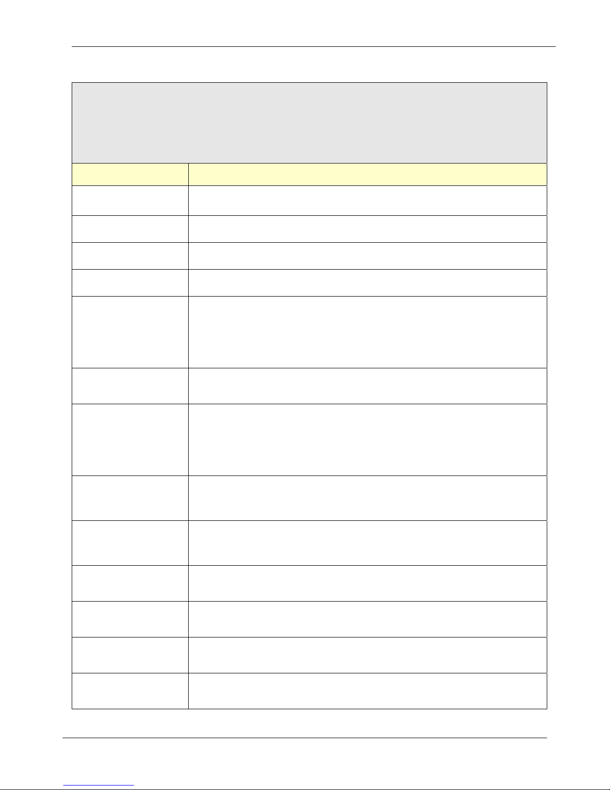
FTP / SYSLOG
The FTP and SYSLOG clients embedded in the COM1000 are used for transporting files and messages created
during event captures. Parameters for FTP and SYSLOG client connections and file naming conventions are
configured on this tab.
Parameter Name Description
FTP Server IP
FTP Server Port
Username
Password
Passive Mode
Directory/Path
File Name
Scheduled FTP Type
IP or Domain Name of destination FTP Server.
Accepts n.n.n.n or abc.123.com (Up to 50 characters)
FTP Server Port. (DEFAULT = 21)
nnnnn = (5 digit value with range between 1 and 65535).
FTP Account Username. (Accepts up to 20 characters).
Example: johndoe
FTP Account Password. (Accepts up to 20 characters).
Example: password123
By default, FTP data connections are initiated by an FTP client but actually established
by the FTP server. Passive Mode forces the data connections to be established by the
client. Passive mode may be required for users who are behind some types of routerbased firewalls or behind a gateway requiring passive transfers.
Options: 0 = Passive Mode Disabled (Default)
1 = Passive Mode Enabled
Sets the Initial Remote Host Directory on the FTP server.
Syntax dictates that you must start the directory path with a slash '/'.
Example: /com1000 (DEFAULT = No path <root>)
FTP Remote File Name Syntax.
Options: 0 = HOSTNAME.txt (Name of device) (DEFAULT)
1 = HOSTNAME_n.txt (Name of device + incrementing number)
2 = HOSTNAME_DATE.txt (Name of device + date)
3 = HOSTNAME_DATE_n.txt (Name of device + date + number)
4 = HOSTNAME_DATE_TIME.txt (Name of device + date + time)
Scheduled FTP Event data type
Options: 0 = None (DEFAULT)
1 = Status (The STATUS events specified in the General Tab)
2 = Log (Individual event LOG)
Scheduled FTP Event time (in minutes)
Scheduled FTP Timer
SYSLOG Server IP
SYSLOG Server Port
Scheduled
SYSLOG Type
Scheduled
SYSLOG Timer
Options: 0 = not active (DEFAULT)
1-65535 = # of minutes between updates (44640 min = 1 month)
IP or Domain Name of destination SYSLOG Server.
Accepts n.n.n.n or abc.123.com (Up to 50 characters)
SYSLOG Server Port. (DEFAULT = 514)
nnnnn = (5 digit value with range between 1 and 65535).
Scheduled SYSLOG Event data type
Options: 0 = None (DEFAULT)
1 = Status (The STATUS events specified in the General Tab)
Scheduled SYSLOG Event time (in minutes)
Options: 0 = not active (DEFAULT)
1-65535 = # of minutes between updates (44640 min = 1 month)
SimpleComTools, LLC 29
Page 30
SimpleComTools, LLC COM1000 – User Manual
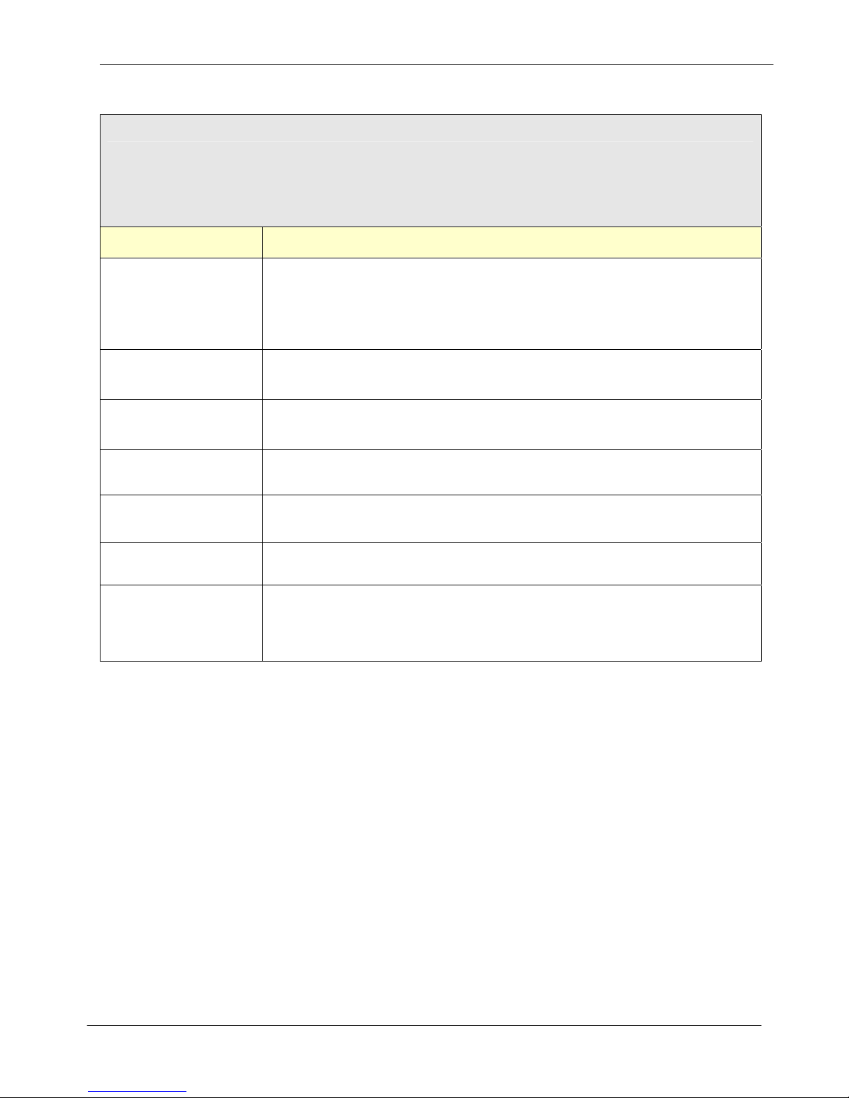
INSTANT MESSAGE
The IM client embedded in the COM1000 is used for transporting status messages.
IM Client connection parameters and message recipients are configured on this tab.
Parameter Name Description
Outbound Message Notification Method.
Options: 0 = None (Default)
IM Protocol
1 = AOL Instant Messenger (AIM)
2 = ICQ
3 = MSN Messenger
IM Server IP
IM Server Port
Username
Password
Nickname
Buddy (1-8)
IP or Domain Name of Instant Message Server.
Accepts n.n.n.n or abc.123.com (Up to 50 characters)
Instant message Server Port.
nnnnn = (5 digit value with range between 1 and 65535). (Default value = 9090)
Instant Message Account Username. Accepts up to 20 characters).
Example: johnedoe
Instant Message Account Password. (Accepts up to 20 characters).
Example: password123
Instant Message Account Nickname.
Accepts up to 20 characters.
Buddies are IM users who will receive ALERT and STATUS messages.
At least one IM BUDDY entry is required for the device IM application to function.
Accepts a 50 character alphanumeric value, including email addresses.
Example: [email protected].
SimpleComTools, LLC 30
Page 31
SimpleComTools, LLC COM1000 – User Manual
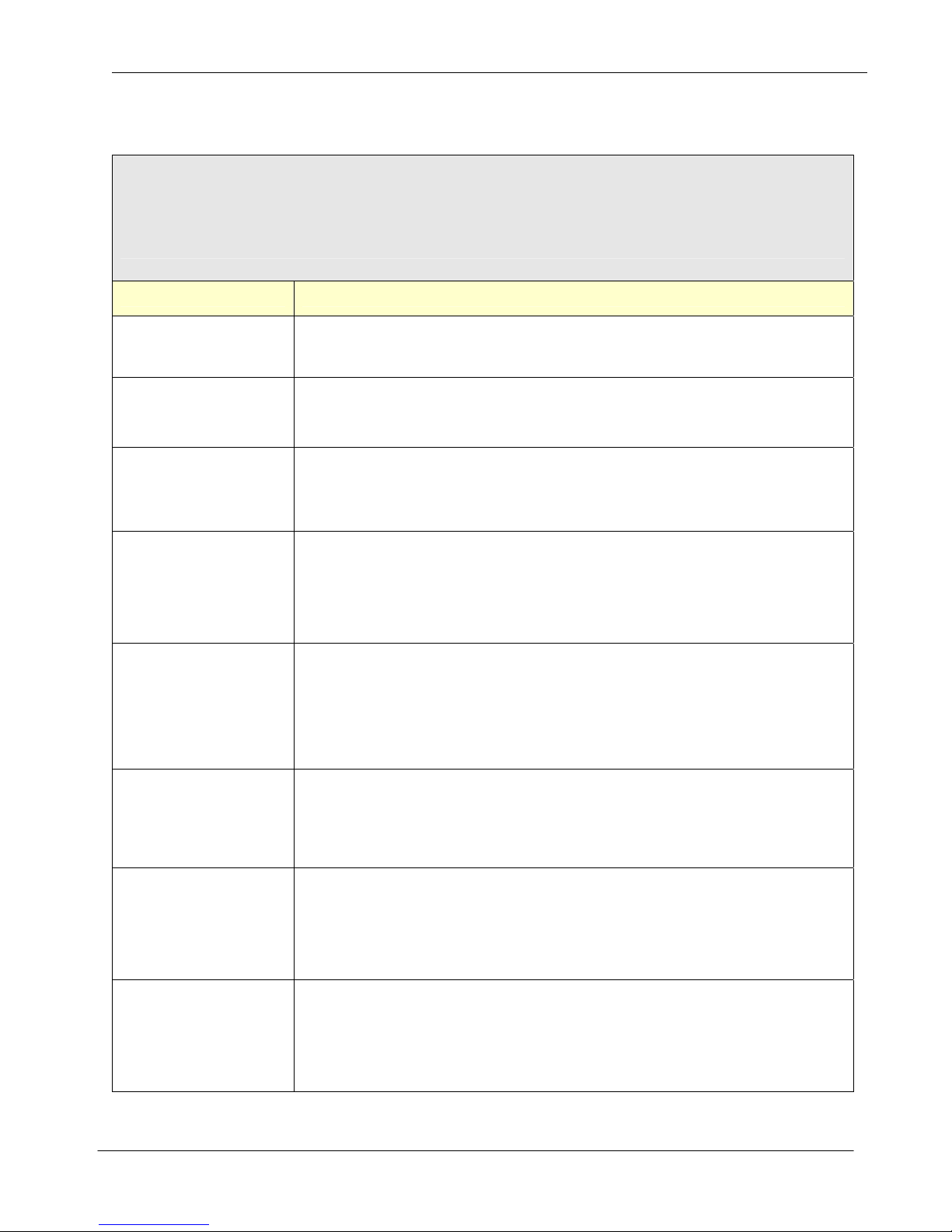
SCHEDULER
The SCHEDULER tab is for configuring the parameters related to scheduled event logging. These options will allow
the scheduled capture of INPUT COUNTS and/or EVENT details. Schedule options include capturing data
persistently (every x minutes) either every day or on a scheduled basis dai ly, weekly, or monthly basis.
Parameter Name Description
Sets the TYPE of log entries being created.
Scheduled Event Type
Schedule Event Timer
Options: 0 = Count Input Events (DEFAULT)
1 = Log Input Event Details
Sets time interval between recurring log entries made within the same 24-hour period.
Options: 0 = no logging (DEFAULT)
1-1440 = number of minutes between log entries
Scheduled Time of Day
Scheduled Day of Week
Scheduled Day or Month
Poll Message
Poll Message
Line Termination
Sets the TIME OF DAY for regularly scheduled logging.
Set the time value using the
format HH:MM. Must enter value in Military time. (Example: 4PM = 16:00)
Options: 00:00 = Midnight (DEFAULT)
Note: Requires that the value DAY OF WEEK or DAY OF MONTH be set as well.
Sets the DAY OF WEEK for regularly scheduled EVENT logging. Set this value if you
want the log to be appended every day. Otherwise, the default value of 0 will ensure
that event data is added to the log daily.
Options: 0 = Every Day (DEFAULT)
1-7 = Day of the Week starting with Sunday. (Sun=1, Mon=2, Tue=3, etc)
Note: Requires that the value DAY OF WEEK or DAY OF MONTH be set as well.
Sets the DAY OF MONTH for regularly scheduled EVENT logging. Set this value if you
do NOT want the log to be appended every day. Otherwise, the default value of 0 will
ensure that event data is added to the log daily.
Options: 0 = Every Day (DEFAULT)
1-31 = Day of the Month. (1=1st day, 2=2nd day, etc)
Note: Triggering once-per-month requires that DAY OF WEEK be set to ‘0’.
The Poll Message is a string of text to be sent out of the RS232 Port. It is designed to
communicate to an external device connected to the Terminal Port. Primarily for
triggering the device to provide a response or data output. This is a one-time command,
and not a complete SEND/EXPECT protocol. (Accepts up to 50 characters)
Poll Message Line Termination. Sets line termination sequence used when sending a
Poll Message string to a device on the Terminal Port.
Options: 0 = CR (Send a Carriage Return after sending string) (DEFAULT)
1 = LF (Send a Line Feed after sending string)
2 = CR+LF (Send a Carriage Return + Line Feed after sending string)
Poll Message string type.
Poll Type
Options: 0 = None
1 = ASCII Text
2 = HEX
SimpleComTools, LLC 31
Page 32
SimpleComTools, LLC COM1000 – User Manual
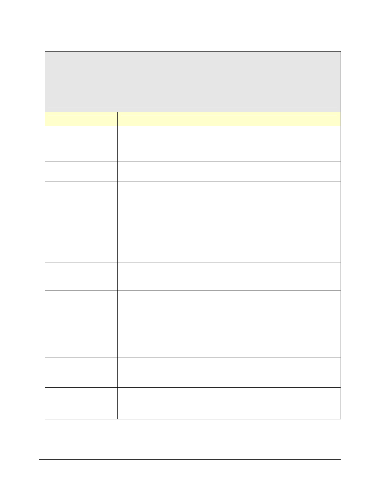
ANALOG INPUT
The Analog Input tab configures the desired Warning and Alarm values (Set Points) for the Analog Input.
Options include High Alarm Set Point, High Warning Set Point, Low Warning Set Point and Low Alarm Set Point:.
Actions include sending data out of the serial port, to sending IP packets, SMS or SMTP or IM messages.
The tab makes it simple to configure the analog set points, the warning and alarm messages, as well as the inten ded
message recipients.
Parameter Name Description
Customized ANALOG Interface Name. A free-text field for the NAME of the interface
Name
Current Value Displays the current Analog value.
which will be used in all UDP, TCP, and SMTP alerts. For SMTP and SMS alerts, this
will be seen as the FROM field. Accepts up to 20 characters.
Example: analoginterface
High Alarm Count
High Warning Count
Low Warning Count
Low Alarm Count
High Alarm Set Point
High Warning Set Point
Low Warning Set Point
Displays the current High Alarm Count.
This is the number of times that this particular Set Point has been reached.
Displays the current High Warning Count.
This is the number of times that this particular Set Point has been reached.
Displays the current Low Warning Count.
This is the number of times that this particular Set Point has been reached.
Displays the current Low Alarm Count.
This is the number of times that this particular Set Point has been reached.
High Alarm Set Point is the highest analog value you wish to allow.
Reaching this value will trigger the selected HIGH ALARM ACTION(S).
Acceptable values range from 0.0 - 30.0, with .1 increments.
(Example: 26.5).
High Warning Set Point is a higher analog value you wish to be warned about.
Reaching this value will trigger the selected HIGH ALARM ACTION(S).
Acceptable values range from 0.0 - 30.0, with .1 increments.
(Example: 20.2).
Low Warning Set Point is a lower analog value you wish to be warned about.
Reaching this value will trigger the selected LOW WARNING ACTION(S).
Acceptable values range from 0.0 - 30.0, with .1 increments.
(Example: 5.2).
Low Alarm Set Point is the lowest analog value you wish to allow.
Low Alarm Set Point
Reaching this value will trigger the selected LOW ALARM ACTION(S).
Acceptable values range from 0.0 - 30.0, with .1 increments.
(Example: 1.5).
SimpleComTools, LLC 32
Page 33

SimpleComTools, LLC COM1000 – User Manual
High Alarm Action = action taken when HIGH ALARM value is reached.
Options: 0 = No Action
1 = Terminal Port (ASCII Data Stream)
2 = RS485 Port (ASCII Data Stream)
3 = UDP Alert
High Alarm Action
High Warning Action
4 = TCP Alert
5 = Send Message
6 = FTP
7 = Relay OPEN
8 = Relay CLOSE
9 = COUNT events
10 = LOG events
(Use a comma for separation of multiple selections.)
High Warning Action = action taken when HIGH WARNING value is reached.
Options: 0 = No Action
1 = Terminal Port (ASCII Data Stream)
2 = RS485 Port (ASCII Data Stream)
3 = UDP Alert
4 = TCP Alert
5 = Send Message
6 = FTP
7 = Relay OPEN
8 = Relay CLOSE
9 = COUNT events
10 = LOG events
(Use a comma for separation of multiple selections.)
Low Warning Action
Low Alarm Action
Low Warning Action = action taken when LOW WARNING value is reached.
Options: 0 = No Action
1 = Terminal Port (ASCII Data Stream)
2 = RS485 Port (ASCII Data Stream)
3 = UDP Alert
4 = TCP Alert
5 = Send Message
6 = FTP
7 = Relay OPEN
8 = Relay CLOSE
9 = COUNT events
10 = LOG events
(Use a comma for separation of multiple selections.)
Low Alarm Action = action taken when LOW ALARM value is reached.
Options: 0 = No Action
1 = Terminal Port (ASCII Data Stream)
2 = RS485 Port (ASCII Data Stream)
3 = UDP Alert
4 = TCP Alert
5 = Send Message
6 = FTP
7 = Relay OPEN
8 = Relay CLOSE
9 = COUNT events
10 = LOG events
(Use a comma for separation of multiple selections.)
SimpleComTools, LLC 33
Page 34

SimpleComTools, LLC COM1000 – User Manual
Customizable High Alarm Message text. This is a free-text field to be used when the
High Alarm Message
High Warning Message
Low Warning Message
Low Alarm Message
High Alarm Action (*AHIGHALARMACT) is set to #1, 2, or 3. This text will be seen as
the message SUBJECT field in SMS or SMTP messages. (Accepts to 20 characters).
Example: site 1 high alarm
Customizable High Warn Message text. This is a free-text field to be used when the
High Warn Action (*AHIGHWARNACT) is set to #1, 2, or 3. This text will be seen as the
message SUBJECT field in SMS or SMTP messages. (Accepts to 20 characters).
Example: site 1 high warn
Customizable Low Warn Message text. This is a free-text field to be used when the Low
Warn Action (*ALOWWARNACT) is set to #1, 2, or 3. This text will be seen as the
message SUBJECT field in SMS or SMTP messages. (Accepts to 20 characters).
Example: site 1 low warn
Customizable Low Alarm Message text. This is a free-text field to be used when the
Low Alarm Action (*ALOWALARMACT) is set to #1, 2, or 3. This text will be seen as
the message SUBJECT field in SMS or SMTP messages. (Accepts to 20 characters).
Example: site 1 low alarm
Event Recipients
UDP Destination IP
UDP Destination Port
TCP Destination IP
TCP Destination Port
Reset Counters
Minimum Analog Voltage
Desired message recipient(s) as detailed in the MESSAGING configuration registers.
(Comma separation for multiple, ie 1,2,3,4,5,6,7,8) Max number = 8.
Destination IP Address of remote UDP Server that will receive Analog messages.
Accepts numeric IP Address or fully qualified domain name (abc.123.com).
(Accepts up to 50 characters)
Destination port of remote UDP Server receiving Analog messages.
nnnnn = (5 digit value with range between 1 and 65535)
Destination IP Address of remote TCP Server receiving Analog messages.
Accepts numeric IP Address or fully qualified domain name (abc.123.com).
(Accepts up to 50 characters)
Destination port of remote TCP Server receiving Analog messages.
nnnnn = (5 digit value with range between 1 and 65535)
Reset the ANALOG COUNTER value after reporting of the counters.
Options: 0 = Disabled (DEFAULT)
1 = Enabled
Minimum voltage output of the chosen sensor. Typically ‘0’, but this may be 1 or 5.
Check the sensor specifications for details..
Maximum Analog Voltage
Maximum voltage output of the chosen sensor. May not be greater than 30 VDC.
Check the sensor specifications for details.
SimpleComTools, LLC 34
Page 35

SimpleComTools, LLC COM1000 – User Manual
Lowest range value of the chosen sensor. This is the lower end of whatever range you
Minimum Output Display
Maximum Output Display
Output Display Extension
Calibration
are trying to measure within. If you were using a temperature probe that had the abilit y
to measure from 32°F-212°F, you would enter the value 32.
Highest range value of the chosen sensor. This is the higher end of whatever rang e you
are trying to measure within. If you were using a temperature probe that had the abilit y
to measure from 32°F-212°F, you would enter the value 212.
Free text extension appended to the analog value output.
Examples of text you may want to enter include:
If you are measuring…. You may want to enter the word…
Temperature Degrees° F
Pressure PSI
Speed MPH
Flow GPM (Gallons p/minute)
Brewery Output Glasses of Beer
Calibrates the COM1000 to match the actual current sensor reading.
If you know the ACTUAL value being measured, you would enter that real value. The
COM1000 will take its current reading, and perform a calculation to come up with the
offset so as to give you a more accurate reading going forward.
Example:
The COM1000 sees the temperature in the room as 76°F.
You believe that the temperature of the room is 74°F.
You would enter the value of ‘74 and the COM1000 would use an offset of ‘2’.
The temperature would now show the reading as 74°F.
SimpleComTools, LLC 35
Page 36
SimpleComTools, LLC COM1000 – User Manual
DIGITAL INPUT (1-4)
The (4) Digital Inputs provide the ability to capture contact closures, log those events and/ or send message
notifications that an event has occurred. The (4) Digital Input tabs are used to configure these inputs with unique
Active and Inactive state names and actions. Options include naming the interfaces, selecting contact closure/switch
types, as well as selecting Actions such as sending data out of the serial port, to sending IP packets, SMS or SMTP
or IM messages.
Parameter Name Description
Customized Digital Input Name. A free-text field for the NAME of the interface which will
Name
Current Value Displays the current Digital Inp ut value.
Current Count Displays the current Digital Input count.
be used in all UDP, TCP, and SMTP alerts. For SMTP and SMS alerts, this will be seen
as the FROM field. Accepts up to 20 characters.
Example: west_door
Switch Type
Active State Action
Inactive State Action
Digital Input Switch Type. The chosen selection will be considered the INACTIVE
STATE for all of the events and messages. For example, if the switch is Normally
Open, then an open switch is INACTIVE. When the switch is closed, it becomes
ACTIVE. The same is true for the reverse. If the switch is Normally Closed, then a
closed switch is INACTIVE and open is considered ACTIVE.
Options: 0 = Normally Closed
1 = Normally Open
Digital Input ACTIVE switch state action. Event that will be triggered when the switch
connected to the digital input changes to the ACTIVE state.
Options: 0 = No Action
1 = Terminal Port (ASCII Data Stream)
2 = RS485 Port (ASCII Data Stream)
3 = UDP Alert
4 = TCP Alert
5 = Send Message
6 = FTP
7 = Relay OPEN
8 = Relay CLOSE
9 = COUNT events
10 = LOG events
(Use comma separation for multiple selections; ie 1,3,7)
Digital Input INACTIVE switch state action. Event that will be triggered when the switch
connected to the digital input changes to the INACTIVE state.
Options: 0 = No Action
1 = Terminal Port (ASCII Data Stream)
2 = RS485 Port (ASCII Data Stream)
3 = UDP Alert
4 = TCP Alert
5 = Send Message
6 = FTP
7 = Relay OPEN
8 = Relay CLOSE
9 = COUNT events
10 = LOG events
(Use comma separation for multiple selections; ie 1,3,7).
SimpleComTools, LLC 36
Page 37

SimpleComTools, LLC COM1000 – User Manual
Customized Digital Input ACTIVE switch state name. A free-text field used when the
Active State Name
Inactive State Name
Active State Message
Inactive State Message
switch is in the ACTIVE state. Name will be used in all UDP, TCP, SMS, and SMTP
messages. For SMS and SMTP, this will be seen as the SUBJECT field.
(Accepts up to 20 characters)
Customized Digital Input INACTIVE switch state name. A free-text field used when the
switch is in the INACTIVE state. Name will be used in all UDP, TCP, SMS, and SMTP
messages. For SMS and SMTP, this will be seen as the SUBJECT field.
(Accepts up to 20 characters)
Customized Digital Input #1 ACTIVE switch state message. A free-text field used when
the switch is in the ACTIVE state. Text is used in all UDP, TCP, SMS, and SMTP
messages. For SMS and SMTP, this will be seen as the SUBJECT field.
(Accepts up to 20 characters)
Customized Digital Input #1 INACTIVE switch state message. A free-text field used
when the switch is in the ACTIVE state. Text is used in all UDP, TCP, SMS, and SMTP
messages. For SMS and SMTP, this will be seen as the SUBJECT field.
(Accepts up to 20 characters)
Event Recipients
UDP Destination IP
UDP Destination Port
TCP Destination IP
TCP Destination Port
Reset Counters
Desired message recipient(s) as detailed in the MESSAGING configuration registers.
(Comma separation for multiple, ie 1,2,3,4,5,6,7,8) Max number = 8.
Destination IP Address of remote UDP Server that will receive Digital Input messages.
Accepts numeric IP Address or fully qualified domain name (abc.123.com).
(Accepts up to 50 characters)
Destination port of remote UDP Server receiving Analog messages.
nnnnn = (5 digit value with range between 1 and 65535)
Destination IP Address of remote TCP Server receiving Digital Input messages.
Accepts numeric IP Address or fully qualified domain name (abc.123.com).
(Accepts up to 50 characters)
Destination port of remote TCP Server receiving Analog messages.
nnnnn = (5 digit value with range between 1 and 65535)
Reset the Digital Input value after reporting of the counters.
Options: 0 = Disabled (DEFAULT)
1 = Enabled
SimpleComTools, LLC 37
Page 38
SimpleComTools, LLC COM1000 – User Manual
RELAY
The on-board relay provides the ability to Open and Close a circuit, giving the device the ability to control external
devices, such as lighting systems, motors, alarms, etc. The Relay tab is used to configure the state names as well
as sending SMS or SMTP or IM messages.
Parameter Name Description
Name
Current State
Relay ‘On’ Alias
Relay ‘Off’ Alias
Relay ‘On’ Message
Relay ‘Off’ Message
Recipients
Name used as Internet HOST and NETBIOS NAME for MS Windows Networks.
Accepts up to 50 alphanumeric characters.
Displays or changes current state of RELAY.
Command without '=n' will display state. Including '=n' will change the state.
Options: 0 = DE-ENERGIZE Relay (Turn it OFF)
1 = ENERGIZE Relay. (Turn it ON)
Customizable Relay ON command. This is a free-text field to be used to create a term
to be interpreted as the *RON AT Command. Example: entering the term ‘engine-on'
would allow for the term 'engine-on' to be used as a command to ENERGIZE the relay.
(Accepts up to 20 characters).
Customizable Relay OFF command. This is a free-text field to be used to create a term
to be interpreted as the *ROFF AT Command. Example: entering the term ‘engine-off'
would allow for the term 'engine-off' to be used as a command to DE-ENERGIZE the
relay. (Accepts up to 20 characters).
Customizable Relay ON (ENERGIZED) message. This is A free-text field used when
the Relay is in the active state. Text is used in all Serial, UDP, TCP, SMS, and SMTP
messages. For SMS and SMTP, this will be seen as the SUBJECT.
Example: :entering the term ‘Engine1-is-On' would allow for the term 'Engine1-is-On' to
be the message sent when the relay is ENERGIZED. (Accepts up to 20 characters)
Customizable Relay ON (ENERGIZED) message. This is A free-text field used when
the Relay is in the active state. Text is used in all Serial, UDP, TCP, SMS, and SMTP
messages. For SMS and SMTP, this will be seen as the SUBJECT.
Example: :entering the term ‘Engine1-is-Off' would allow for the term 'Engine1-is-Off' to
be the message sent when the relay is ENERGIZED. (Accepts up to 20 characters)
Desired Relay State message recipient(s) as detailed in the MESSAGING configuration
registers. (Comma separation for multiple, ie 1,3,8). Max number = 8.
Interval of timer the relay will stay energized after being turned on.
Relay Auto-Off Time
Scheduled Relay
Activation Timer
Scheduled Relay
Activation Time of Day
Scheduled Relay
Activation Day of Week
Scheduled Relay
Activation Day of Month
Options: 0 = not active (No auto-off feature)
1-65535 = number of seconds (65535 sec = 18.2 hours)
Sets the time interval for recurring relay triggering to take place within the same 24-hour
period. This requires that Relay Auto-Off Time
Options: 0 = no timer active (DEFAULT)
1-1440 = number of minutes between relay triggers
Sets the TIME OF DAY for regularly scheduled relay triggering.
using the format HH:MM. Must enter value in Military time.
Note: Requires that the value DAY OF WEEK or DAY OF MONTH be set as well.
Sets the DAY OF WEEK for regularly scheduled relay triggering. Only set this value if
you do NOT want the relay to be triggered every day.
Options: 0 = Every Day (DEFAULT)
1-7 = Day of the Week starting with Sunday. (Sun=1, Mon=2, Tue=3, etc)
Sets the DAY OF MONTH for regularly scheduled relay triggering. Set this value if you
do NOT want the relay to be triggered every day.
Options: 0 = Every Day (DEFAULT)
1-31 = Day of the Month. (1=1
SimpleComTools, LLC 38
also be set.
st
day, 2=2nd day, etc)
Set the time value
Page 39
SimpleComTools, LLC COM1000 – User Manual
TEMPERATURE
The Temperature tab configures the desired Warning and Alarm values (Set Points) for the COM1000s internal
Temperature sensor. Options include High Alarm Set Point, High Warning Set Point, Low Warning Set Point and
Low Alarm Set Point:. Actions include sending data out of the serial port, logging to a file, sending IP packets, SMS
or SMTP or IM messages, transporting data via FTP or sending Syslog messages.
The tab makes it simple to configure the analog set points, the warning and alarm messages, as well as the inten ded
message recipients.
Parameter Name Description
Customized Temperature Name. A free-text field for the NAME of the interface which
Name
Current Temperature Displays the current Temperature value.
will be used in all UDP, TCP, and SMTP alerts. For SMTP and SMS alerts, this will be
seen as the FROM field. Accepts up to 20 characters.
High Temp Alarm Count
High Temp
Warning Count
Low Temp
Warning Count
Low Temp
Alarm Count
High Temp Alarm
Set Point
High Temp Warning
Set Point
Low Temp Warning
Set Point
Displays the current High Temperature Alarm Count.
This is the number of times that this particular Set Point has been reached.
Displays the current High Temperature Warning Count.
This is the number of times that this particular Set Point has been reached.
Displays the current Low Temperature Warning Count.
This is the number of times that this particular Set Point has been reached.
Displays the current Low Temperature Alarm Count.
This is the number of times that this particular Set Point has been reached.
High Temperature Alarm Set Point is the highest Temperature value you wish to allow.
Reaching this value will trigger the selected HIGH ALARM ACTION(S).
Acceptable values range from 0.0 - 30.0, with .1 increments.
(Example: 26.5).
High Temperature Warning Set Point is a higher Temperature value you wish to be
warned about. Reaching this value will trigger the selected HIGH ALARM ACTION(S).
Acceptable values range from 0.0 - 30.0, with .1 increments.
(Example: 20.2).
Low Temperature Warning Set Point is a lower Temperature value you wish to be
warned about. Reaching this value will trigger the selected LOW WARNING
ACTION(S). Acceptable values range from 0.0 - 30.0, with .1 increments.
(Example: 5.2).
Low Temperature Alarm Set Point is the lowest Temperature value you wish to allow.
Low Temp Alarm
Set Point
Reaching this value will trigger the selected LOW ALARM ACTION(S).
Acceptable values range from 0.0 - 30.0, with .1 increments.
(Example: 1.5).
SimpleComTools, LLC 39
Page 40

SimpleComTools, LLC COM1000 – User Manual
High Temperature Alarm Action = action taken when HIGH ALARM value is reached.
Options: 0 = No Action
1 = Terminal Port (ASCII Data Stream)
2 = RS485 Port (ASCII Data Stream)
3 = UDP Alert
High Temp
Alarm Action
High Temp
Warning Action
4 = TCP Alert
5 = Send Message
6 = FTP
7 = Relay OPEN
8 = Relay CLOSE
9 = COUNT events
10 = LOG events
(Use a comma for separation of multiple selections.)
High Temperature Warning Action = action taken when HIGH WARNING value is
reached.
Options: 0 = No Action
1 = Terminal Port (ASCII Data Stream)
2 = RS485 Port (ASCII Data Stream)
3 = UDP Alert
4 = TCP Alert
5 = Send Message
6 = FTP
7 = Relay OPEN
8 = Relay CLOSE
9 = COUNT events
10 = LOG events
(Use a comma for separation of multiple selections.)
Low Temp
Warning Action
Low Temp
Alarm Action
Low Temperature Warning Action = action taken when LOW WARNING value is
reached.
Options: 0 = No Action
1 = Terminal Port (ASCII Data Stream)
2 = RS485 Port (ASCII Data Stream)
3 = UDP Alert
4 = TCP Alert
5 = Send Message
6 = FTP
7 = Relay OPEN
8 = Relay CLOSE
9 = COUNT events
10 = LOG events
(Use a comma for separation of multiple selections.)
Low Temperature Alarm Action = action taken when LOW ALARM value is reached.
Options: 0 = No Action
1 = Terminal Port (ASCII Data Stream)
2 = RS485 Port (ASCII Data Stream)
3 = UDP Alert
4 = TCP Alert
5 = Send Message
6 = FTP
7 = Relay OPEN
8 = Relay CLOSE
9 = COUNT events
10 = LOG events
(Use a comma for separation of multiple selections.)
SimpleComTools, LLC 40
Page 41

SimpleComTools, LLC COM1000 – User Manual
Customizable High Temperature Alarm Message text. This is a free-text field to be used
High Temp
Alarm Message
High Temp
Warning Message
Low Temp
Warning Message
Low Temp
Alarm Message
when the High Alarm Action (*AHIGHALARMACT) is set to #1, 2, or 3. This text will be
seen as the message SUBJECT field in SMS or SMTP messages. (Accepts to 20
characters). Example: site 1 high alarm
Customizable High Temperature Warn Message text. This is a free-text field to be used
when the High Warn Action (*AHIGHWARNACT) is set to #1, 2, or 3. This text will be
seen as the message SUBJECT field in SMS or SMTP messages. (Accepts to 20
characters). Example: site 1 high warn
Customizable Low Temperature Warning Message text. This is a free-text field to be
used when the Low Warn Action (*ALOWWARNACT) is set to #1, 2, or 3. This text will
be seen as the message SUBJECT field in SMS or SMTP messages. (Accepts to 20
characters). Example: site 1 low warn
Customizable Low Temperature Alarm Message text. This is a free-text field to be used
when the Low Alarm Action (*ALOWALARMACT) is set to #1, 2, or 3. This text will be
seen as the message SUBJECT field in SMS or SMTP messages. (Accepts to 20
characters). Example: site 1 low alarm
Event Recipients
UDP Destination IP
UDP Destination Port
TCP Destination IP
TCP Destination Port
Reset Counters
Temp Calibration
Desired message recipient(s) as detailed in the MESSAGING configuration registers.
(Comma separation for multiple, ie 1,2,3,4,5,6,7,8) Max number = 8.
Destination IP Address of remote UDP Server that will receive Analog messages.
Accepts numeric IP Address or fully qualified domain name (abc.123.com).
(Accepts up to 50 characters)
Destination port of remote UDP Server receiving Analog messages.
nnnnn = (5 digit value with range between 1 and 65535)
Destination IP Address of remote TCP Server receiving Analog messages.
Accepts numeric IP Address or fully qualified domain name (abc.123.com).
(Accepts up to 50 characters)
Destination port of remote TCP Server receiving Analog messages.
nnnnn = (5 digit value with range between 1 and 65535)
Reset the ANALOG COUNTER value after reporting of the counters.
Options: 0 = Disabled (DEFAULT)
1 = Enabled
Calibrates the COM1000 to match the reading of another TEMP sensor. (Accepts a '+'
or '-' 5 digit value between 1 and 32767). If you know the actual TEMP the COM1000
should be displaying in the Current Temperature field (AT*TEMP), then simply enter the
difference (or offset) between the real TEMP and the Current TEMP. The COM1000 will
use this offset to give the proper readings going forward.
Example: The COM1000 shows a TEMP of 78 degrees and another thermostat shows
a TEMP of 80 degrees, enter the value 2 as the offset. If the COM1000 shows a TEMP
of 80 degrees and a thermostat shows a TEMP of 78 degrees, enter the value -2 as the
offset.
SimpleComTools, LLC 41
Page 42
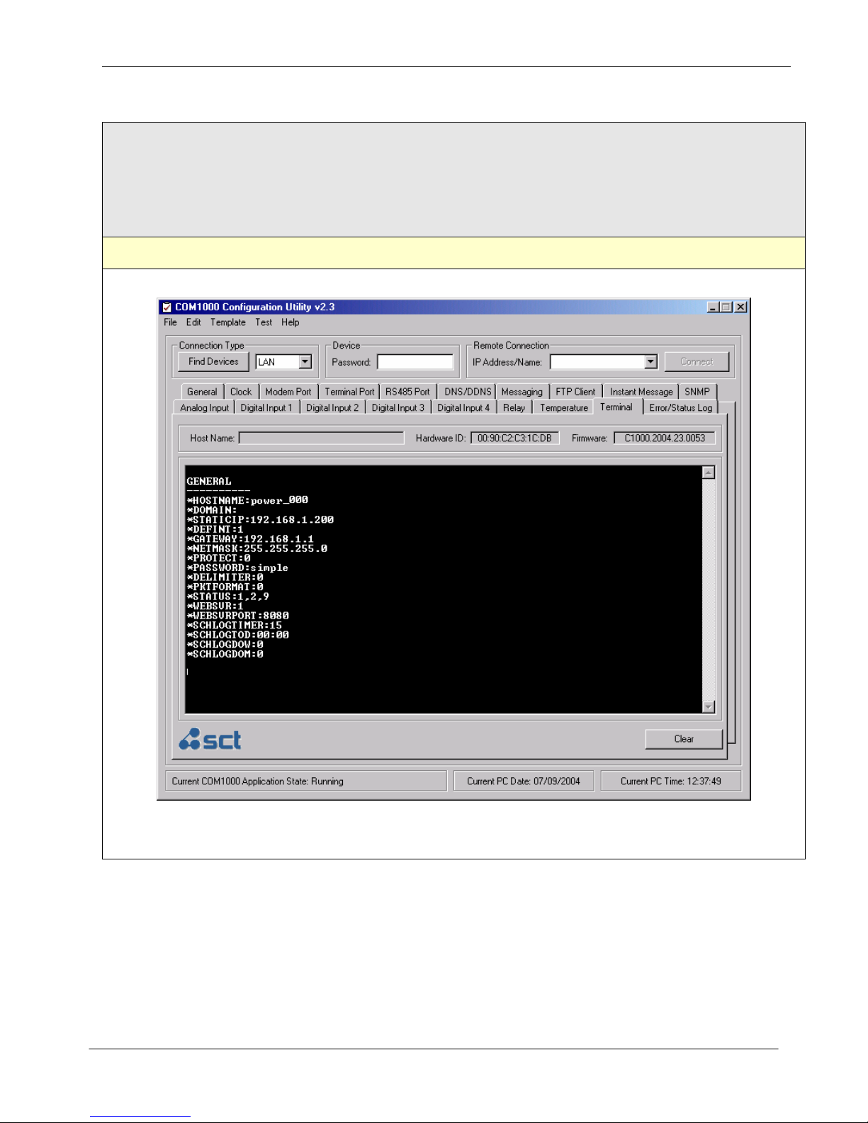
SimpleComTools, LLC COM1000 – User Manual
AT COMMAND TERMINAL
The AT Command Terminal provides a quick and easy way to access the COM1000 parameters via a command line
interface. By using a set of standard (and non-standard) AT Commands, experienced professionals can access individual
registers directly, without the need for a GUI. The interface also supports full Microsoft Windows Cut, Copy, and Paste
functionality.
SimpleComTools, LLC 42
Page 43
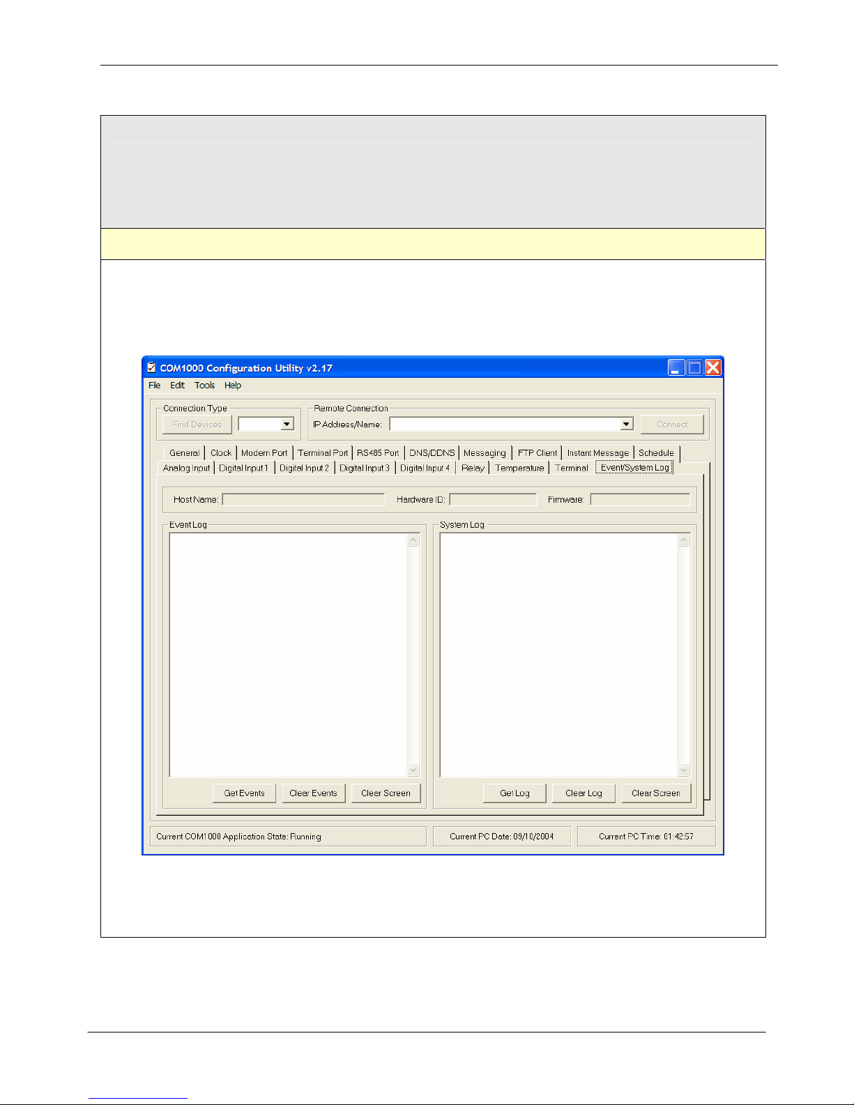
SimpleComTools, LLC COM1000 – User Manual
ERROR/EVENT WINDOW
The Error/Event Log window provides a real-time status indication of all running functions and process in a plain text
format. The interface also supports full Microsoft Windows Cut, Copy, and Paste functionality.
SimpleComTools, LLC 43
 Loading...