

Page 1
Installation Guide
Page 2

© 2017 EcoFactor, Inc.
Page 3
1
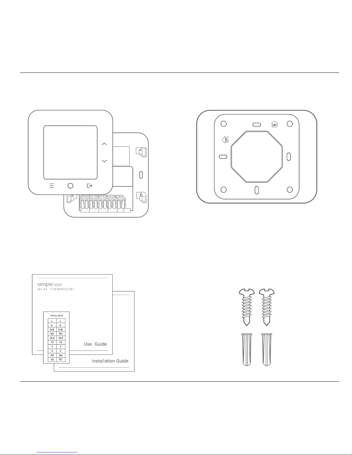
Thermostat and Wall Plate
Manuals and Wiring Labels
Screws and Wall Anchors
Trim Plate
The wall plate comes snapped into
the back of the thermostat.
The optional trim plate can
cover unnished areas under the
old thermostat. It can be used
horizontally or vertically.
In the Box
Page 4
2
For a Wi-Fi connected installation, visit install.thesimple.com to
sign up for an account and view on-line instructions.*
Installing this thermostat usually takes around 45 minutes, depending
on your existing thermostat and wiring requirements. A common wire
(C-wire) or other 24VAC power source is required.
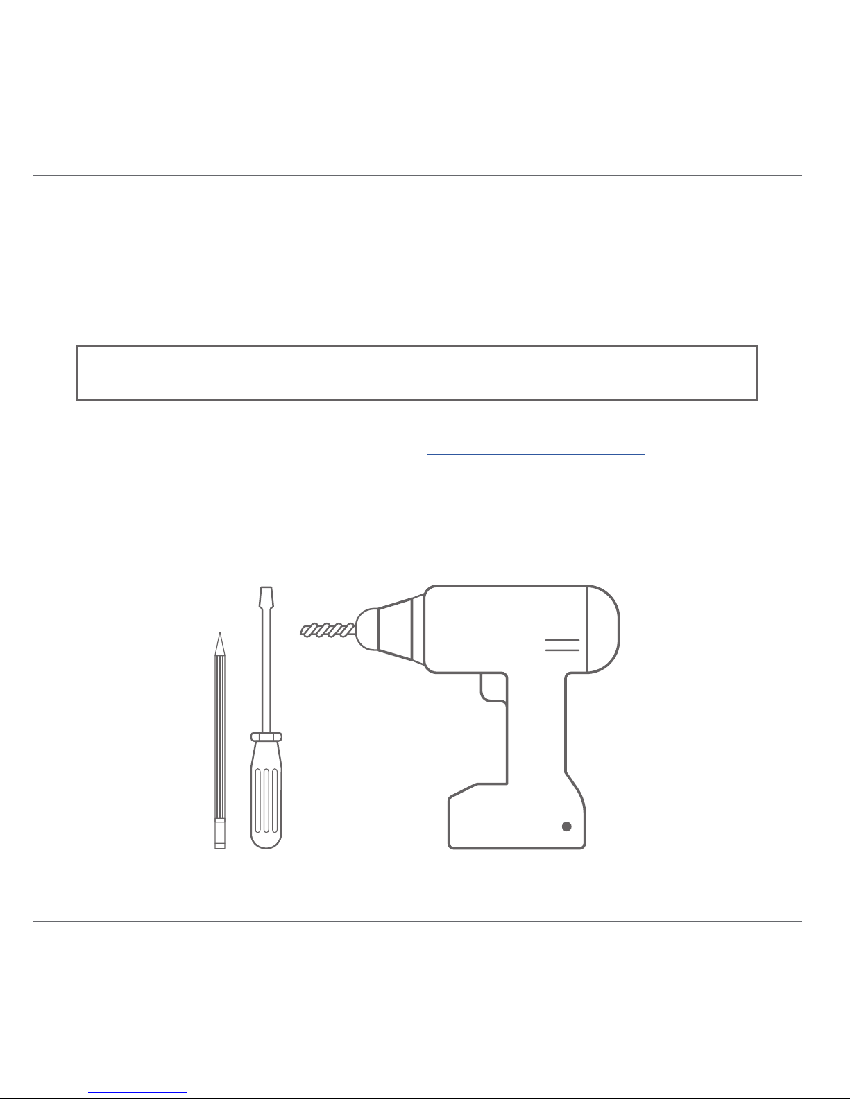
Recommended Tools
*
If you are eligible for professional installation, online install is not supported.
WARNING: Line voltage and millivolt systems are not supported.
Tools and Preparation
Page 5
3
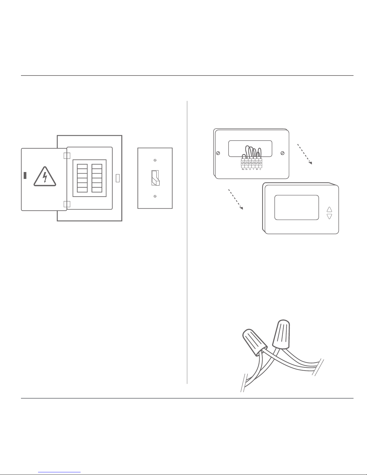
Step 1 – Remove power to the
system
Step 2 – Remove the existing
thermostat faceplate
Locate your breaker or master
power switch that controls your
heating and/or cooling system, and
turn off the power.
Take a picture of existing wiring
as a reference.
If you see thick wires and plastic
caps, then STOP. The S100 is not
compatible with 120V line voltage
systems.
Installation Steps
Page 6
4
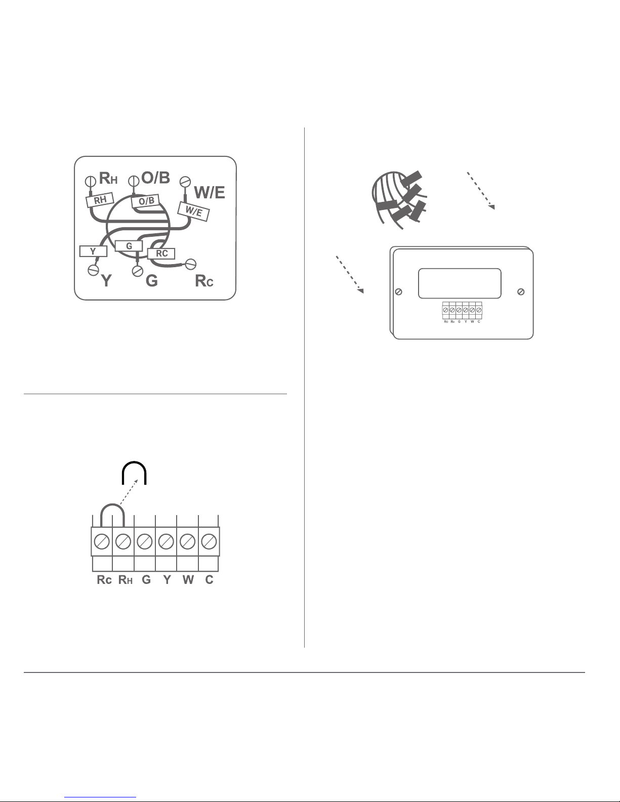
Step 3 – Attach wire labels
The jumper wire can be discarded.
Your thermostat has an internal
jumper.
Match the supplied wire labels to the
existing wiring. If there is no match,
consult the Wiring Guide after this
section.
Disconnect the existing wiring
before removing the wall plate.
You can wrap wires around a
pencil so they do not fall into the
wall.
Step 4 – Remove any existing RC or
RH jumper wire
Step 5 – Remove the existing
wall plate
Page 7
5
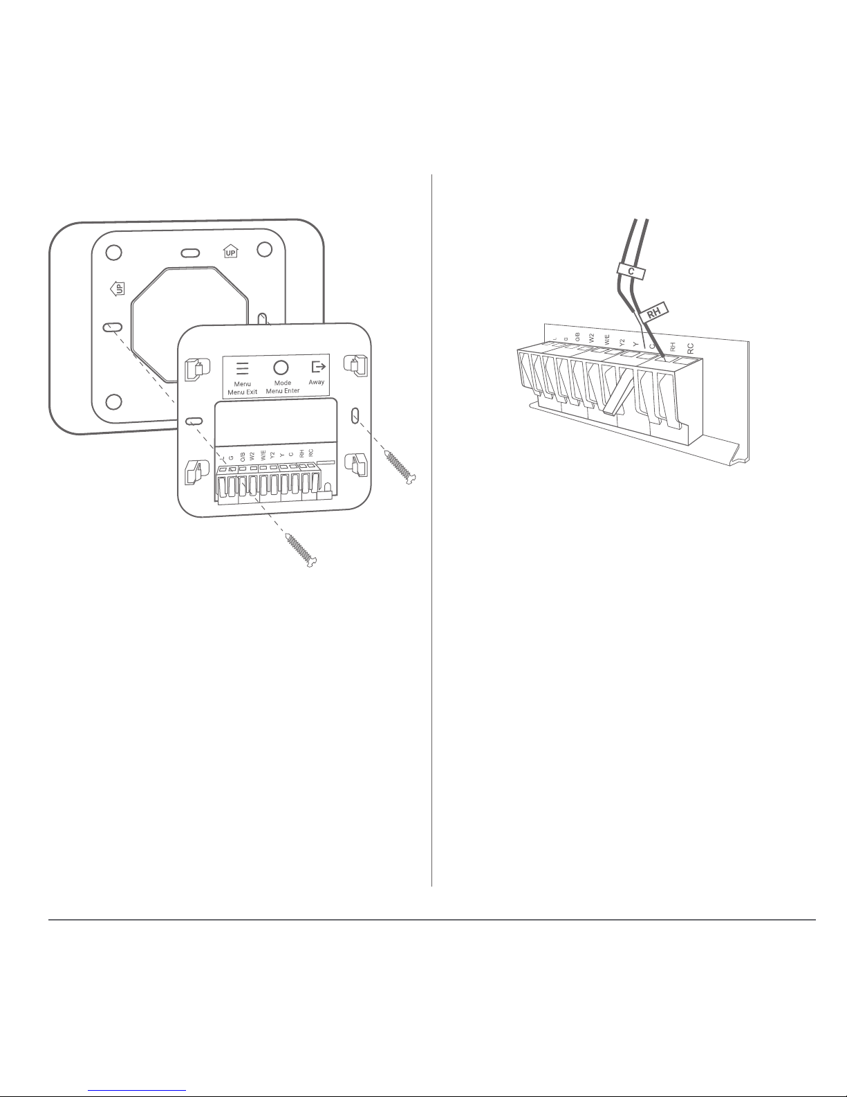
If the optional trim plate is needed,
place it between the wall plate and
the wall.
Match the wire labels to the
terminal names on the wall plate.
The wall plate has levers for each
terminal position. Lift the lever
before inserting the wire. Push the
lever back down to lock the wire in
place.
Step 6 – Mount the wall plate Step 7 – Connect the wires
Page 8
6
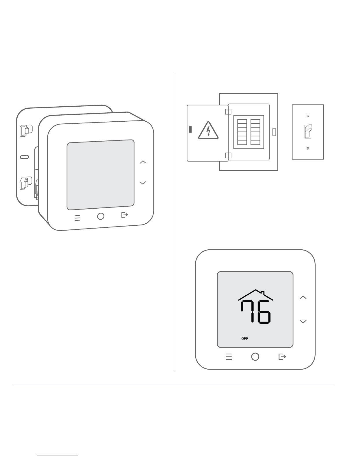
Ensure that all four corners are
snapped into place.
Verify that the thermostat display
turns on. The system will be OFF
when rst installed. Do not press
buttons or change system settings
until it has been fully congured.
Step 8 – Attach thermostat to wall
plate
Step 9 – Turn power back on
Page 9
7
Match your existing wiring to the S100 terminals using the table below.
Terminal Function
RC 24VAC for cooling.
RH 24VAC for heating. If there is only one R wire (R, RH, RC) then
connect it to RH. May be labeled V or VR for Lennox.
C Common wire. May be labeled X for Rheem, Ruud, or Lennox;
B for Trane, York.
Y 1st stage compressor, A/C or heat pump. May be labeled M
for Lennox.
Y2 2nd stage compressor, A/C or heat pump.
W/E 1st stage heating, or heat pump emergency heat. Some
heat pumps may designate emergency heat as E or X2, or
auxiliary heat as W1 or W2. May be labeled Y for Lennox.
W2 2nd stage heating. Not used for heat pumps.
O/B Heat pump changeover valve.
G Fan control. Optional for gas furnace, required for A/C and
electric heat strip or furnace. May be labeled F for Lennox.
L Fault detection for heat pumps.
Wiring Guide
Page 10
8
This thermostat is intended to be connected to your Wi-Fi network. However,
it is fully functional as a conventional thermostat when disconnected.
If you wish to use the thermostat as a disconnected device, the system
heating and cooling conguration must be congured using the Advanced
Menu before use.
If the thermostat was previously congured to use Wi-Fi, this connected
conguration must rst be cleared with a Factory Reset.
The default conguration for your thermostat is for conventional heating
and cooling. If you have a heat pump or other conguration, do not use the
MODE button until the thermostat has been congured.
Press and hold both the MENU tand MODE buttons for 5 seconds to enter the
Advanced Menu.
Press DOWN until RESET is shown.
Press MODE and CONFIRM will start ashing.
Hold MODE for 5 seconds to clear all settings.
Step 1: Factory Reset (if needed)
Disconnected Conguration
Page 11
9
Press and hold both the MENU and MODE buttons for 5 seconds to enter the
Advanced Menu.
Press DOWN until >HVAC is shown.
Press MODE to enter the HVAC conguration menu.
The following settings are available:
HVAC TYPE HEAT COOL
HEAT ONLY
COOL ONLY
HT PUMP
HT PUMP EMR
Type of system connected to this
thermostat.
This setting is read-only when Wi-Fi is
congured.
CHANGEOVER O – COOL ON
B – HEAT ON
Applies only to heat pumps.
Determines whether heat or cool is
active. Most heat pumps are O, but
Rheem/Ruud typically use B.
If your heat pump is heating when
it should be cooling, and vice-versa,
please change this setting.
FURNACE GAS
ELECTRIC
Applies only to forced air systems,
including heat pump emergency heat.
Step 2: Enter System Conguration
Page 12
10
The time and date must be set manually for timed features to work
properly. Daylight Savings Time changes must also be applied manually.
This is only necessary when not connected, because the time and date
of the thermostat are set automatically over the Internet when connected
to Wi-Fi.
Press MENU to enter the menu system.
Press DOWN until >SET TIME is shown.
Press MODE to enter the Set Time menu.
The following settings are available:
HOUR nn
Set the hour of the time. If the 12 hour clock,
then the choices are 1-12.
MINUTE nn
Set the minute of the time, 00-59.
AM/PM AM
PM
This choice is only shown for a 12 hour clock.
Step 3: Set Time and Date
Use MENU to exit from the >SET TIME menu.
Page 13
11
MONTH JAN JUL
FEB AUG
MAR SEP
APR OCT
MAY NOV
JUN DEC
Set the current month.
DAY nn
Set day, with range of 1 to last day of
current month.
YEAR nnnn
Set the year, with range of 2016 to
2100.
Press DOWN until >SET DATE is shown.
Press MODE to enter the Set Date menu.
The following settings are available:
Page 14
12
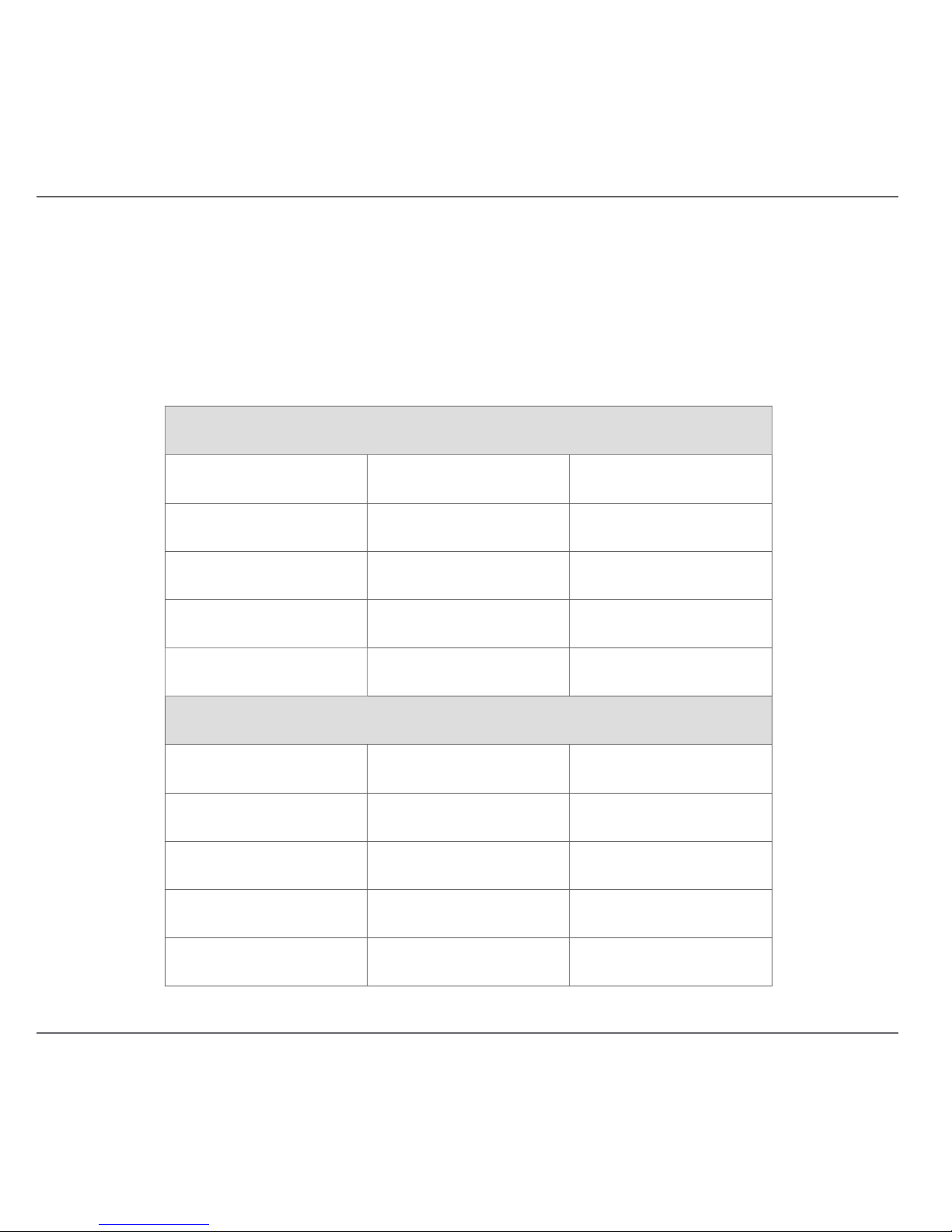
The thermostat has a built-in schedule that is used when disconnected.
This standard schedule is based on Energy Star 2009 guidelines.
You can use the menu to turn off the schedule, or you can connect your
thermostat to Wi-Fi and personalize your schedule.
Weekday (Mon-Fri)
Interval Heat Setpoint Cool Setpoint
6 am 70 F, 21.2 C 78 F, 25.6 C
8 am 62 F, 16.7 C 85 F, 29.4 C
6 pm 70 F, 21.2 C 78 F, 25.6 C
10 pm 62 F, 16.7 C 82 F, 27.8 C
Weekend (Sat-Sun)
Interval Heat Setpoint Cool Setpoint
7 am 70 F, 21.2 C 78 F, 25.6 C
10 am 62 F, 16.7 C 85 F, 29.4 C
6 pm 70 F, 21.2 C 78 F, 25.6 C
11 pm 62 F, 16.7 C 82 F, 27.8 C
Disconnected Schedule
Page 15

100.2-00-201704
 Loading...