

Page 1
TM
Photo phone
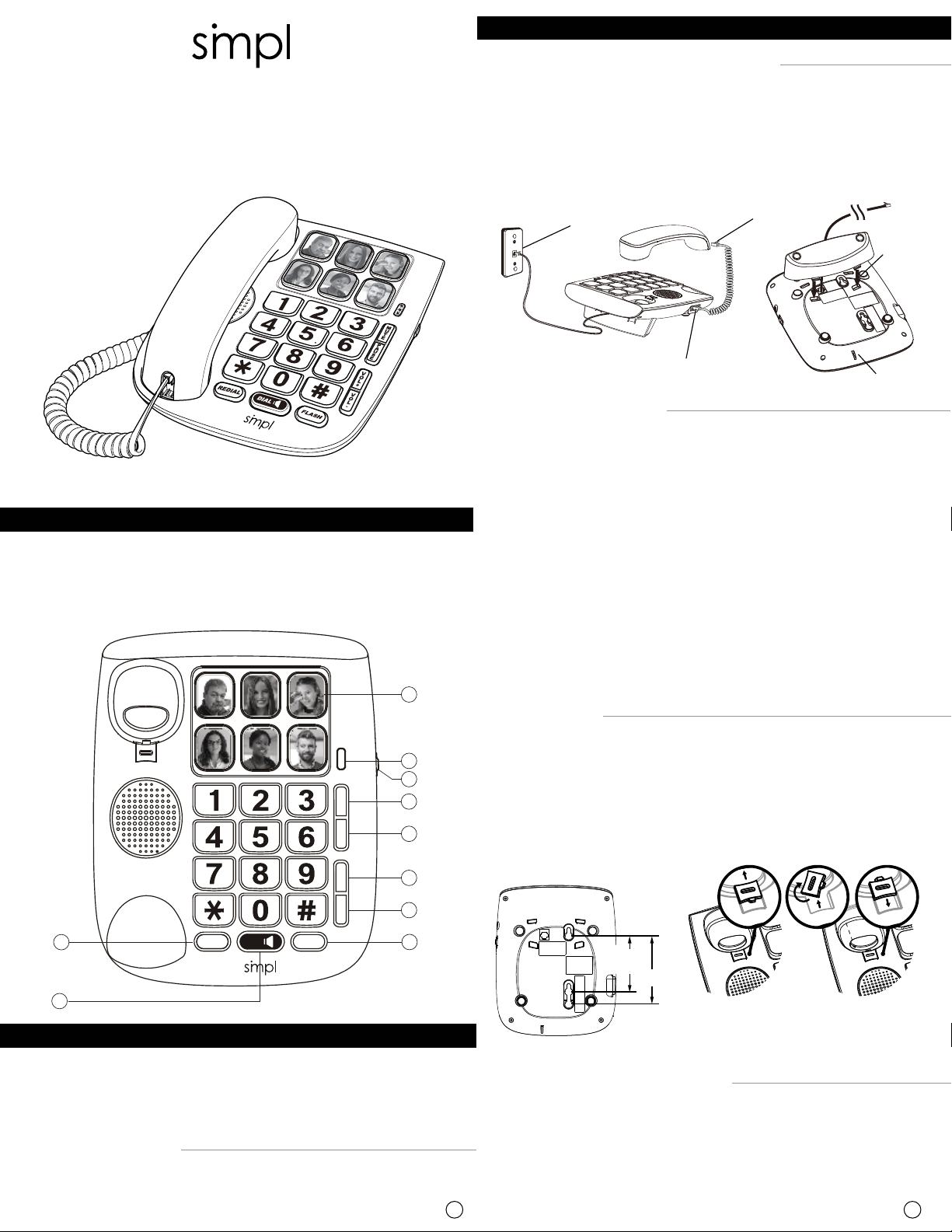
INSTALLING THE PHONE
Your phone should be placed on a level surface
- Plug one end of the spiral cord into the handset at (A), and the other end
into the socket on the left side of the phone (B). See Fig. 2
- Plug the telephone cord into the socket at the bottom of the set and into
the wall socket (C).
- For desktop position, always install the foot stand (D). See Fig. 3
ENGLISH
USER'S GUIDE
1
2
M
U
T
E
P
A
U
S
E
V
O
L
+
V
O
L
-
10
9
FLASHREDIAL DIAL
BOX INCLUDES
1. Phone Base 4. Handset cord (spiral)
2. Phone cord 5. Foot stand
3. Handset 6. User Guide
Connecting your phone:
- Connect the handset.
- Plug the telephone line into telephone socket.
3
4
5
6
7
8
Fig. 1
1 2
Fig. 2
(C)
Wall socket
(A)
Handset socket
(D)
(B)
Spiral cord socket
Microphone
BASE STATION KEYS (Fig. 1)
1: 6 memory photo keys
2: Light indicator - Mute on (microphone off)/ Ringer (incoming call)
3: Ringer volume switch
4: Mute key (microphone off)
5: Pause key
6: Handset volume increase
7: Handset volume decrease
8: Flash key - Switches between two calls on the same line
9: Dial Handsfree key - press the orange key to hear a dial tone, then
dial the number
10: Last number redial key
WALL MOUNTING
- Remove the foot stand.
- Turn over the wall mounting peg (small grooved plastic part) on the base.
- Drill two 0.25 inch (6 mm) holes 4 inch (10 cm) apart.
- Fit two wall plugs and screw in wood screws (3.5 mm in diameter and 30
mm long).
- Mount the base on the 2 screws by pulling it downwards.
Fig. 3
3.25"
(8.3 cm)
4" (1 cm)
Horizontal (i.e table)
(no adjustment required)
INSTALL PICTURES ON THE PHOTO BUTTONS
- Remove the clear button cap by pressing inward on the vertical edge while lifting
the cap upwards.
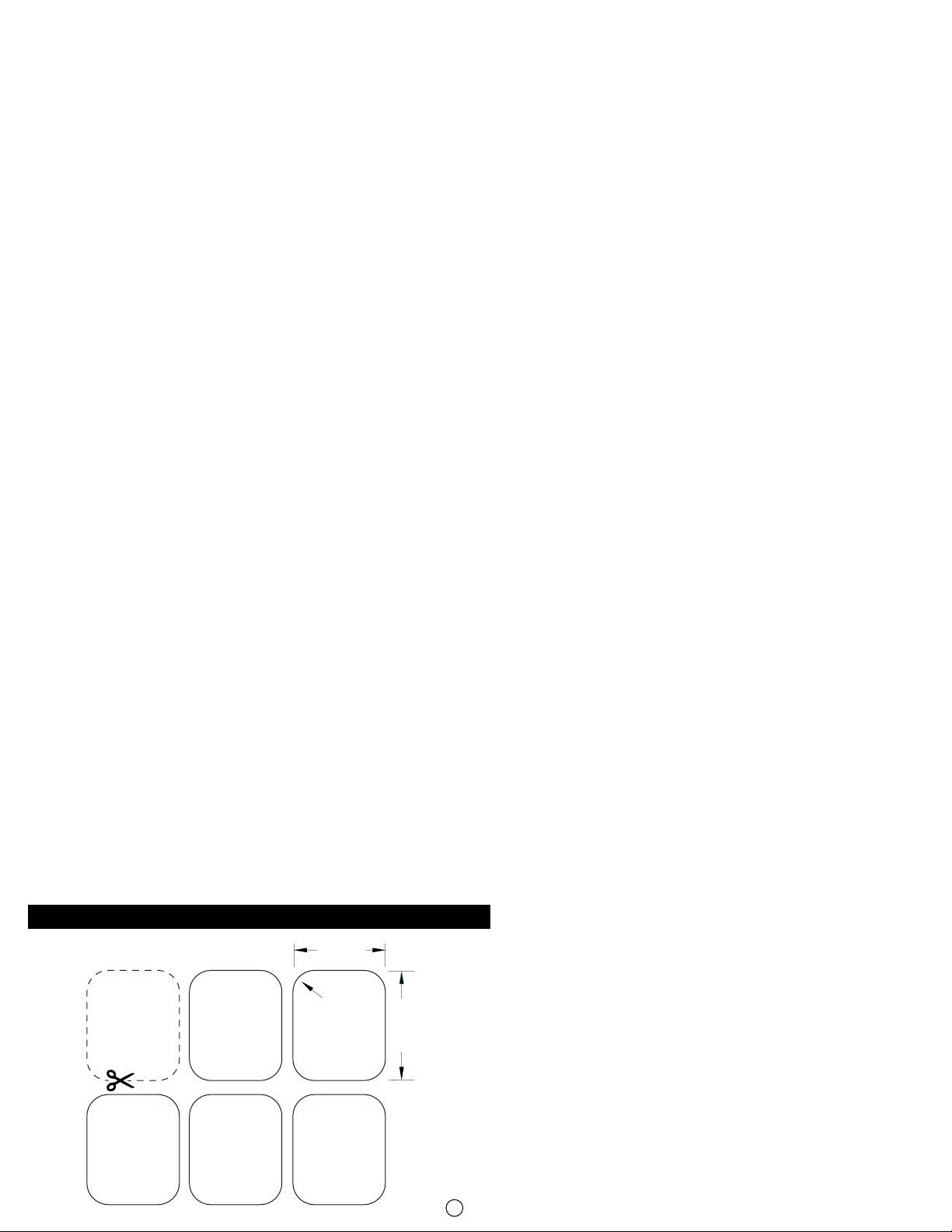
- Cut the picture using the template shown in the Photo Cutting Guide section at
end of this guide.
- Insert the picture inside the cap and then press the cap firmly downwards on top
of the black button.
Wall Mounted
(slide off tab and re-insert
so notch is protruding,
see 3 circled drawings)
Page 2
V
O
L
+
USING THE PHONE
SAFETY
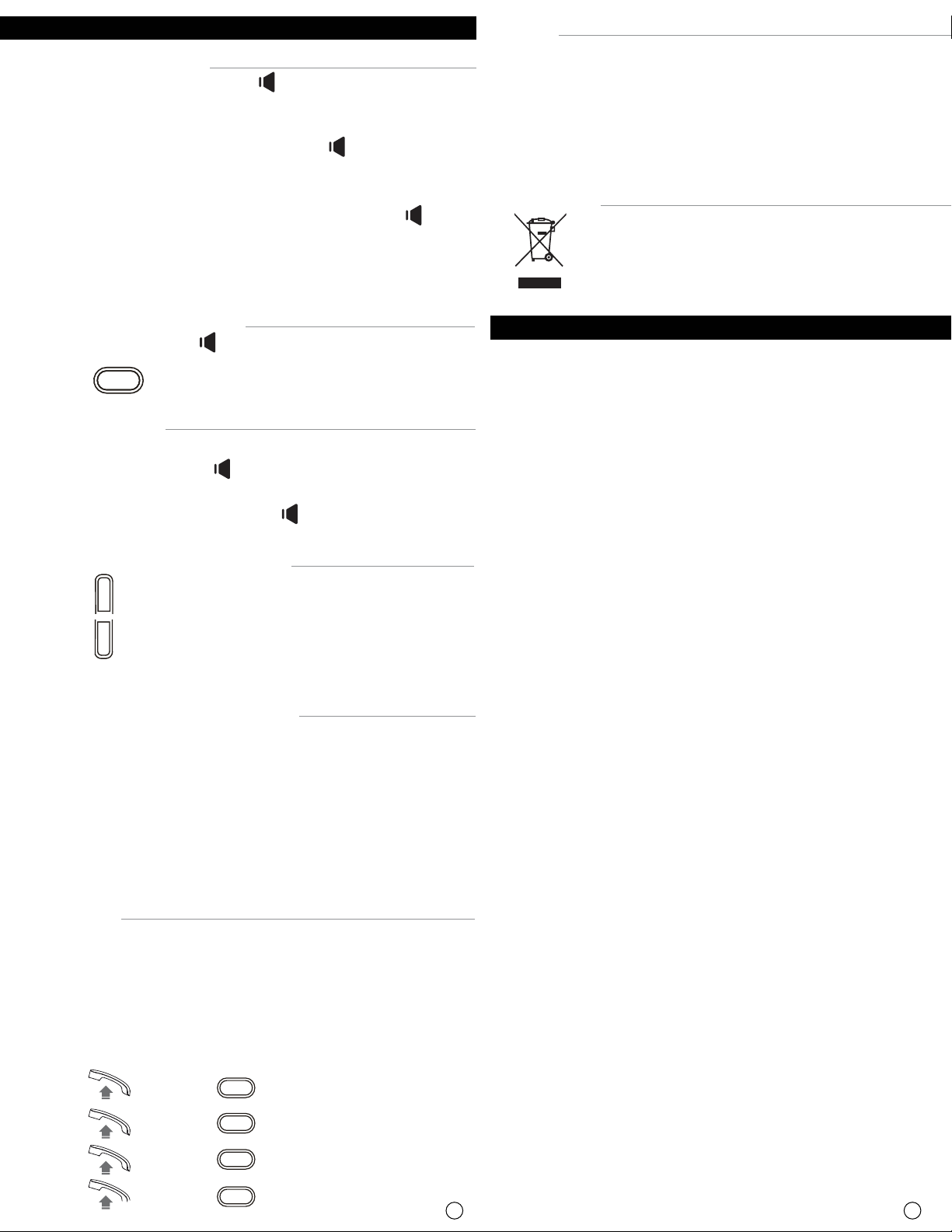
MAKE A CALL/ REDIAL
- Pick up the handset or press 'DIAL ' orange key.
- Dial the number or press one of the 6 Photo keys (with pictures). See
paragraph 'Store number'.
• If someone answered and you pressed DIAL button, then pick up
handset and have your conservation. (not for typical speakerphone
conversations - microphone works from less than 12 inches only)
Do not use your telephone to notify a gas leak or other potential explosion
hazard.
Do not open your device to avoid risk of electrical shock.
Your telephone must be located in a dry place away from hot, humid and
direct sunlight condition.
ENVIRONMENT
• If no one answered hangup the handset or press the DIAL button
again to hang up.
At the end of the communication:
- Hang up by replace the handset on its base
DIAL BACK AN OUTGOING NUMBER
REGULATORY COMPLIANCE
This symbol means that your inoperative appliance must be
collected separately and not mixed with the household waste.
Help us to protect the environment in which we live!
- Pick up handset or press key.
FCC Statement
- Press key.
ANSWERING A CALL
- To answer:
Pick up the handset or press key. (handsfree mode).
- To end a call:
Replace the handset on its base or press key.
HANDSET/EAR-PIECE VOLUME ADJUSTMENT
- Press to increase the volume level.
- Press to decrease the volume level.
- 4 levels selectable.
STORING NUMBERS FOR (6) PHOTO BUTTONS
- Pick up handset.
- Select one picture key, and long-press it for a few seconds until you
hear a 'beep'.
- Enter the number by using keypad. (3-second pause (one press) may be
required when entering a sequence of numbers for photo button dialing
in facilities.)
- Press again the same picture key.
The number is registered.
FLASH TIME
The Flash key engages the call waiting feature, if available form your
service provider, allowing you to accept a second incoming call. Flash
time is the amount time (under 1 second) to switch from one call to
another. Flash time adjustment may be required if installing the phone
in a facility. (based on system requirements).
If an adjustment is required:
REDIAL
V
O
L
+
V
O
L
-
- / *#*100 / = 100ms
- / *#*300 / = 300ms
- / *#*600 / = 600ms
- / *#*1000 / = 1000ms
FLASH
FLASH
FLASH
FLASH
This equipment has been tested and found to comply with the limits for a Class B
digital device, pursuant to part 15 of the FCC rules. These limits are designed to
provide reasonable protection against harmful interference in a residential
installation. This equipment generates, uses and can radiate radio frequency
energy and, if not installed and used in accordance with the instructions, may
cause harmful interference to radio communications. However, there is no
guarantee that interference will not occur in a particular installation. If this
equipment does cause harmful interference to radio or television reception, which
can be determined by turning the equipment off and on, the user is encouraged to
try to correct the interference by one or more of the following measures:
- Reorient or relocate the receiving antenna.
- Increase the separation between the equipment and receiver.
- Connect the equipment into an outlet on a circuit different from that to which
the receiver is connected.
- Consult the dealer or an experienced radio/TV technician for help.
To assure continued compliance, any changes or modifications not expressly
approved by the party responsible for compliance could void the user’s authority
to operate this equipment. (Example- use only shielded interface cables when
connecting to computer or peripheral devices).
This device complies with Part 15 of the FCC Rules. Operation is subject to the
following two conditions: (1) this device may not cause harmful interference, and
(2) this device must accept any interference received, including interference that
may cause undesired operation.
Caution! Any changes or modifications not expressly approved by the party
responsible for compliance could void the user's authority to operate the equipment.
FCC - PART 68
This equipment complies with Part 68 of the FCC rules and the requirements
adopted by the ACTA. On the bottom of this equipment is a label that contains,
among other information, a product identifier in the format US:C70-56010. If
requested, this number must be provided to the telephone company. This
equipment uses the following USOC jacks: RJ-11.
3 4
Page 3
REN (RINGER EQUIVALENT NUMBERS) STATEMENT Notice:
The Ringer Equivalence Number (REN) assigned to each terminal device provides
an indication of the maximum number of terminals allowed to be connected to a
telephone interface. The termination on an interface may consist of any
combination of devices subject only to the requirement that the sum of the Ringer
Equivalence Numbers of all the devices does not exceed 5.
ATTACHMENT LIMITATIONS STATEMENT
Notice: This equipment meets telecommunications network protective,
operational and safety requirements as prescribed in the appropriate Terminal
Equipment Technical Requirements document(s). This is confirmed by marking the
equipment with the Industry Canada certification number. The Department does
not guarantee the equipment will operate to the user's satisfaction. Before
installing this equipment, users should ensure that it is permissible to be
connected to the facilities of the local telecommunications company. The
equipment must also be installed using an acceptable method of connection. The
customer should be aware that compliance with the above conditions may not
prevent degradation of service in some situations. Repairs to certified equipment
should be coordinated by a representative designated by the supplier. Any repairs
or alterations made by the user to this equipment, or equipment malfunctions, may
give the telecommunications company cause to request the user to disconnect the
equipment. Users should ensure for their own protection that the electrical ground
connections of the power utility, telephone lines and internal metallic water pipe
system, if present, are connected together. This precaution may be particularly
important in rural areas. Caution: Users should not attempt to make such
connections themselves, but should contact the appropriate electric inspection
authority, or electrician, as appropriate.
WARNING: This product contains chemicals known to the
State of California to cause cancer and birth defects or other
reproductive harm.
TECHNICAL SUPPORT: DO NOT RETURN UNIT TO RE-SELLER.
Please call 1-833-237-4675 or email [email protected].
For WARRANTY SERVICE, contact us first.
USA: Simpl Technology, 340 Royal Poinciana Way,
Suite 317/317, Palm Beach, Florida 33480.
CANADA; 200 Vinyl Ct. 2’nd Floor Woodbridge, ON L4L 4A3.
PHOTO CUTTING GUIDE
13/16 inch
(21 mm)
3/16 inch
(4.9 mm)
1 inch
(25 mm)
5
 Loading...