

Page 1
Copyright © 2014 SimPhonics, Incorporated, All Rights Reserved
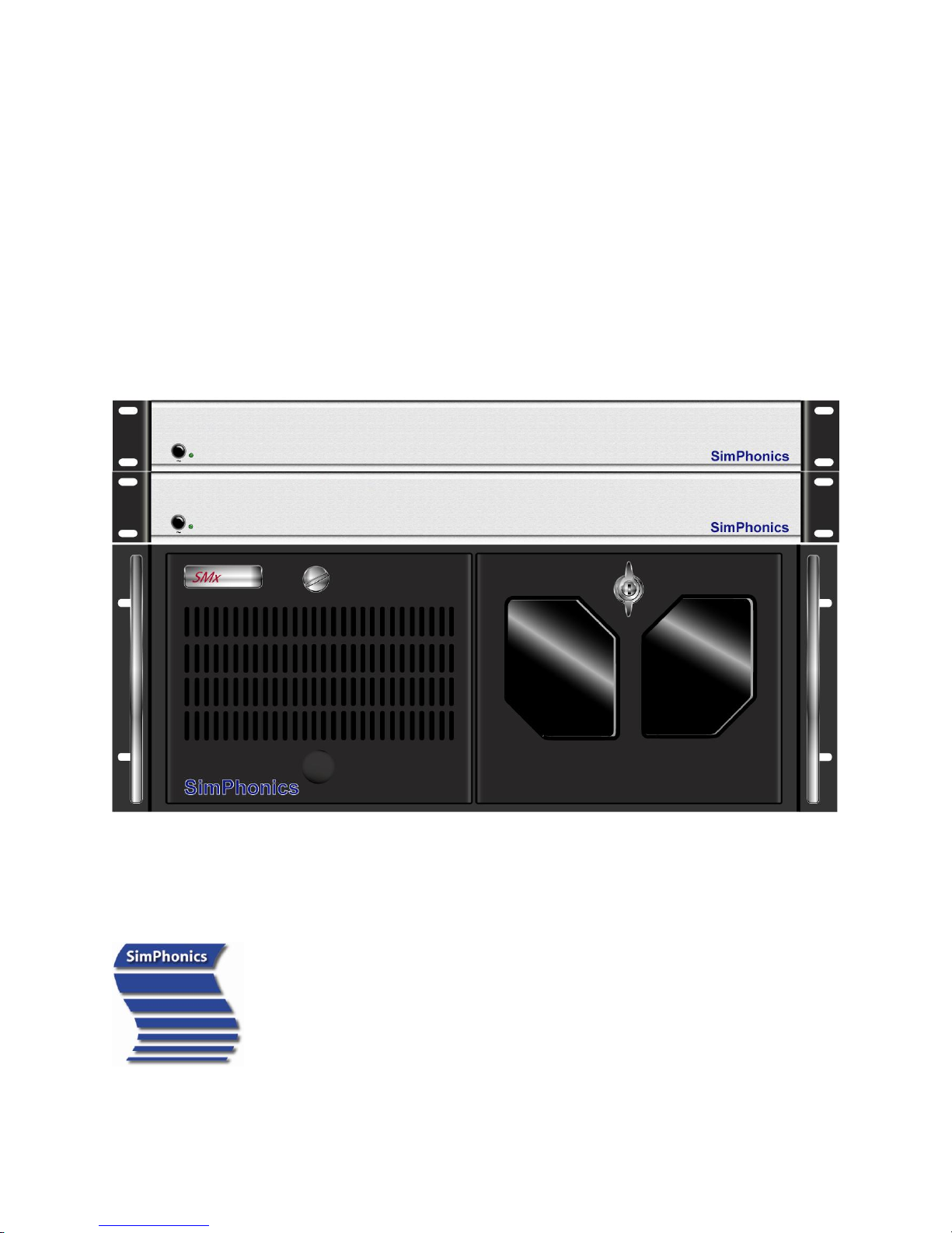
SMx Audio System
User’s Manual
Page 2

SMx Audio System User's Manual, V1.41
SimPhonics, Inc.
Page 2 of 77
Page 2 of 77
Copyright © 2014 SimPhonics, Incorporated, All Rights Reserved
Contents
1 Preface ............................................................................... 8
1.1 Trademarks and Copyrights ..................................................................... 8
1.2 Before Reading this Document ................................................................. 8
1.3 Revision History ..................................................................................... 9
1.4 Terms and Acronyms ............................................................................ 11
1.5 References .......................................................................................... 11
2 Introducing SMx ................................................................. 12
2.1 What is an SMx System? ....................................................................... 13
2.2 Complete Audio and I/O System Solution ................................................ 13
2.3 SMx Terminology ................................................................................. 13
3 System Architectu r e ............................................................ 13
3.1 Overall System Block Diagram ............................................................... 15
3.2 SMx Audio System ............................................................................... 16
3.3 SMx Super Mixer .................................................................................. 17
3.4 Individual Mixers .................................................................................. 18
3.5 Individual Mixer Module ........................................................................ 19
4 Hardware .......................................................................... 20
4.1 Specifications ...................................................................................... 20
4.2 Electrical Characteristics ....................................................................... 21
4.3 Audio Performance ............................................................................... 21
4.4 Transport Delay ................................................................................... 21
4.5 Reliability and Maintainability ................................................................ 21
4.6 CPU Chassis ........................................................................................ 22
4.7 Motherboard and Processor.................................................................... 23
4.8 Diskless Operation ................................................................................ 23
4.9 SMX Breakout box ................................................................................ 24
4.10 Cable Limitations ................................................................................. 24
4.11 Recommended Mating Connectors .......................................................... 25
4.12 SMX PCI DSP Card ................................................................................ 26
4.13 Simulated Hardware ............................................................................. 27
4.14 Sound Cards ........................................................................................ 27
4.14.1 Setting the Sample Rate Conversion Quality ............................................ 27
4.14.2 Controlling the Sound Cards .................................................................. 28
4.15 Power-up and down Sequence ............................................................... 29
4.15.1 Powering Up the System ....................................................................... 29
4.15.2 Powering Down the System ................................................................... 29
5 SMx System I n t e r c o nnect ..................................................... 29
5.1 SMx Breakout Box DIP Switch Settings ................................................... 30
5.1.1 Master/Slave DIP Switch ....................................................................... 30
5.1.2 Phantom Power Switches....................................................................... 31
5.2 Connecting SMx Cards to SMx Master Boxes ............................................ 32
5.3 8 Channel System ................................................................................ 33
5.4 16 Channel System .............................................................................. 34
5.5 24 Channel System .............................................................................. 35
5.6 32 Channel System .............................................................................. 36
5.7 40 Channel System .............................................................................. 37
Page 3

SMx Audio System User's Manual, V1.41
SimPhonics, Inc.
Page 3 of 77
Page 3 of 77
Copyright © 2014 SimPhonics, Incorporated, All Rights Reserved
5.8 48 Channel System .............................................................................. 38
5.9 56 Channel System .............................................................................. 39
5.10 64 Channel System .............................................................................. 40
6 Software Ins t a llation ........................................................... 41
6.1 Minimum Software Requirements ........................................................... 41
6.2 Installing V+ ....................................................................................... 41
6.3 Installing the SMx Audio System Software ............................................... 42
6.4 Updating the SMx Audio System Software ............................................... 43
6.5 Configuring SMx within V+ .................................................................... 44
7 Registry Settings ................................................................ 46
7.1 Changing Registry Settings.................................................................... 47
8 Using V+ with SMx .............................................................. 48
8.1 Application Examples ............................................................................ 48
8.2 The SMx Super Mixer ............................................................................ 49
8.3 SMx I/O Devices for the SMx Audio System ............................................. 49
8.3.1 SMx Analog In Gain Boost Device ........................................................... 50
8.3.2 SMx Analog In Meters Device ................................................................. 51
8.3.3 SMx Analog In to Analog Out Mixer Device .............................................. 52
8.3.4 SMx Analog Out Master Volume Device ................................................... 53
8.3.5 SMx Analog Out Meters Device ............................................................... 55
8.3.6 SMx Wave In Mixer Device .................................................................... 56
8.3.7 SMx Wave Out Meters Device................................................................. 57
8.3.8 SMx Wave out Mixer Device ................................................................... 58
8.3.9 SMx Wave Out to Wave in Mixer Device .................................................. 59
8.3.10 SMx Status Device ............................................................................... 60
8.3.11 Simulated Hardware Mode ..................................................................... 60
8.4 “2103 SMx W I/O Select to A I/O” Object ................................................ 63
8.4.1 “2103 SMx W I/O Select to A I/O” .......................................................... 63
8.5 “2023 SMx Local ICS” Object ................................................................. 64
8.5.1 Local ICS Only ..................................................................................... 64
8.5.2 Networked ICS versus Local ICS ............................................................. 64
8.5.3 Object 2023 ........................................................................................ 64
8.5.4 STATIC DATA ....................................................................................... 65
8.5.5 SIDETONE ........................................................................................... 65
8.5.6 BE CAREFUL WHEN SETTING UP THE AI AND AO CHANNELS ...................... 66
8.5.7 DO NOT USE MORE THAN ONE ICS WITH THE SAME PARAMETERS ............. 66
8.5.8 SAMPLE WORKSHEET ............................................................................ 66
8.5.9 PRACTICAL APPLICATION ...................................................................... 67
8.6 Super Mixer V+ Examples .................................................................... 68
8.6.1 Controlling the Super Mixer’s Master Gains .............................................. 68
8.6.2 Monitoring the Super Mixer’s Meters ....................................................... 69
8.6.3 Controlling the Super Mixer’s AI to AO Mixer ............................................ 71
8.6.4 Controlling the Super Mixer’s WO to AO Mixer .......................................... 72
8.6.5 Controlling the Super Mixer’s WO to WI Mixer .......................................... 73
8.6.6 Controlling the Super Mixer’s AI to WI Mixer ............................................ 74
8.7 Run-Time Messages .............................................................................. 75
9 Troubleshoot ing .................................................................. 75
9.1 Common Problems with Power ............................................................... 75
9.2 System Power Supply ........................................................................... 76
Page 4

SMx Audio System User's Manual, V1.41
SimPhonics, Inc.
Page 4 of 77
Page 4 of 77
Copyright © 2014 SimPhonics, Incorporated, All Rights Reserved
9.3 Safety ................................................................................................. 76
9.4 Handling Your System ........................................................................... 76
9.5 Warranty & RMA Information ................................................................. 76
9.5.1 Requesting an RMA Number .................................................................. 77
9.6 Contact Information ............................................................................. 77
Page 5

SMx Audio System User's Manual, V1.41
SimPhonics, Inc.
Page 5 of 77
Page 5 of 77
Copyright © 2014 SimPhonics, Incorporated, All Rights Reserved
List of Figures
Figure 1, SMx System Architecture ............................................................................. 14
Figure 2, Overall System Block Diagram ...................................................................... 15
Figure 3, SMx Audio System ...................................................................................... 16
Figure 4, SMx Super Mixer ......................................................................................... 17
Figure 5, SMx Mixer Matrix ........................................................................................ 18
Figure 6, Single SMx Mixer Module Showing all 4,096 Gain Controls ............................... 19
Figure 7, Typical SMx PC Chassis................................................................................ 22
Figure 8, SMXB0B-10 Front View ................................................................................ 24
Figure 9, SMXB0B-10 Rear View ................................................................................. 24
Figure 10, Switchcraft Plug Physical Dimensions ........................................................... 25
Figure 11, SMx DSP Card .......................................................................................... 26
Figure 12, Creative Sound Blaster PCI Card Control Panel .............................................. 28
Figure 13, SMx Playback Controls Exposed by Windows ................................................. 28
Figure 14, Breakout Box Master/Slave Dip Switch ......................................................... 30
Figure 15, Breakout Box Phantom Power Switches ........................................................ 31
Figure 16, Connecting SMx Cards to Master Boxes ........................................................ 32
Figure 17, 8 Channel SMx System Connection Diagram ................................................. 33
Figure 18, 16 Channel SMx System Connection Diagram ............................................... 34
Figure 19, 24 Channel SMx System Connection Diagram ............................................... 35
Figure 20, 32 Channel SMx System Connection Diagram ............................................... 36
Figure 21, 40 Channel SMx System Connection Diagram ............................................... 37
Figure 22, 48 Channel SMx System Connection Diagram ............................................... 38
Figure 23, 56 Channel SMx System Connection Diagram ............................................... 39
Figure 24, 64 Channel SMx System Connection Diagram ............................................... 40
Figure 25, V+ Platform Configure Window ................................................................... 44
Figure 26, SMx Configuration Window ......................................................................... 45
Figure 27, Run Dialog Box ......................................................................................... 47
Figure 28, SMx I/O Devices ....................................................................................... 49
Figure 29, SMx Analog in Gain Boost Device ................................................................ 50
Figure 30, SMx Analog in Meters Device ...................................................................... 51
Figure 31, SMx Analog In to Analog Out Mixer Device ................................................... 52
Figure 32, SMx 64 Master Attenuators (Volumes) ......................................................... 53
Figure 33, SMx Analog Out Master Volume Device ........................................................ 54
Figure 34, SMx Analog Out Meters Device ................................................................... 55
Figure 35, SMx Wave In Mixer Device ......................................................................... 56
Figure 36, SMx Wave Out Meters Device ..................................................................... 57
Figure 37, SMx Wave Out Mixer Device ....................................................................... 58
Figure 38, SMx Wave Out to Wave In Mixer Device ....................................................... 59
Figure 39, SMx Status Device .................................................................................... 60
Figure 40, SMx Simulated Hardware Mode Status Ports ................................................. 60
Figure 41, AI Gain Boost Example .............................................................................. 68
Figure 42, AO Master Volume Example ........................................................................ 68
Figure 43, AI VU Meter Example ................................................................................. 69
Figure 44, AO VU Meter Example ................................................................................ 70
Figure 45, WO VU Meter Example ............................................................................... 70
Figure 46, Analog In to Analog Out Mixer Example ....................................................... 71
Figure 47, Wave Out to Analog Out Mixer Example ....................................................... 72
Figure 48, Wave Out to Wave In Mixer Example ........................................................... 73
Figure 49, Analog In to Wave In Mixer Example ........................................................... 74
Figure 50, Run Time System Message Window ............................................................. 75
Page 6

SMx Audio System User's Manual, V1.41
SimPhonics, Inc.
Page 6 of 77
Page 6 of 77
Copyright © 2014 SimPhonics, Incorporated, All Rights Reserved
Page 7

SMx Audio System User's Manual, V1.41
SimPhonics, Inc.
Page 7 of 77
Page 7 of 77
Copyright © 2014 SimPhonics, Incorporated, All Rights Reserved
List of Tables
Table 1. SMx Physical Specifications .......................................................................... 20
Table 2. SMx Power Requirements ............................................................................. 20
Table 3. Operating and Storage Conditions ................................................................. 20
Table 4. Electrical Characteristics .............................................................................. 21
Table 5. Audio Performance Specifications .................................................................. 21
Table 6, Chassis Options ........................................................................................... 22
Table 7. Motherboard Minimum Performance Characteristics ......................................... 23
Table 8 Cable Limitations .......................................................................................... 24
Table 9, 8 Channel SMx System Parts List ................................................................... 33
Table 10. 16 Channel SMx System Parts List ............................................................... 34
Table 11. 24 Channel SMx System Parts List ............................................................... 35
Table 12. 32 Channel SMx System Parts List ............................................................... 36
Table 13. 40 Channel SMx System Parts List ............................................................... 37
Table 14. 48 Channel SMx System Parts List ............................................................... 38
Table 15, 56 Channel SMx System Parts List ............................................................... 39
Table 16. 64 Channel SMx System Parts List ............................................................... 40
Table 17, MISC Registry Key ...................................................................................... 47
Page 8
SMx Audio System User's Manual, V1.41
SimPhonics, Inc.
Page 8 of 77
Page 8 of 77
Copyright © 2014 SimPhonics, Incorporated, All Rights Reserved
1 Preface
1.1 Trademarks and Copyrights
SimPhonics, V+, VPLus, SMx, and/or other SimPhonics products referred to in this site are
either trademarks or registered trademarks of SimPhonics. Other products and company
names that are mentioned may be the trademarks of their respective owners. All rights not
expressly granted herein are reserved.
Copyright © 1998, 2005 SimPhonics Incorporated, Tampa Florida. All rights reserved. All
other trademarks are property of their respective owners with all rights reserved.
Any trademarks shown throughout this document are the property of their respective
owners. V+, V+, SMx are trademarks of SimPhonics, Incorporated.
This document was authored using Microsoft Word 2003 and is maintained at the
SimPhonics web site in .DOC format. This document may be copied freely for any purpose.
1.2 Before Reading this Document
The reader should be familiar with the V+ Visual
Programming System, in particular the use of I/O devices
and ports. The V+ Programming System User Manual is
available from at this URL and is the software engine for the
SMx system and is the only means of controlling the SMx
behavior. The SMx audio system is designed for use in
advanced applications requiring basic knowledge of digital
audio sampling theory, real-time systems, and a good
understanding of modern desktop PC architecture. There are
additional V+ I/O devices that may be attached to the SMx
system to extend the capabilities. To review these devices, click here.
Page 9

SMx Audio System User's Manual, V1.41
SimPhonics, Inc.
Page 9 of 77
Page 9 of 77
Copyright © 2014 SimPhonics, Incorporated, All Rights Reserved
Version
Revision Description
Date
0.1
Pre-release.
8 October 1998
1.0
Initial Release.
29 January 2002
1.1
Added information regarding front SMx panel phone jack and volume
control and updated system block diagram, pages 9 & 11.
15 April 2002
1.2
Changed to the new SMx mixer architecture. Version 2.0 Build 104 of
the SMx Audio System Driver.
26 July 2002
1.3
Updated minimum requirements for system computer.
01 August 2002
1.4
Added “Amplitude Modulation - Single Side Band Radios in V+” section.
11 September 2002
1.5
Added SMx drawings and “tested cable lengths” data. Added section
“Connecting SMx Cards to SMx Master Boxes.”
09 April 2003
1.6
Updated “cable limitations” section. Added section “Extending SMx
Master-to-Slave Connections.”
25 April 2003
1.7
Changed fiber optic cables on drawing – “Connecting SMx Cards to
Master Boxes.”
08 May 2003
1.8
Updated document to reference VComm.
19 May 2003
1.9
Removed “BAL” from rear of SMXB0B-10 channel labels; updated DIP
Switch Settings section.
23 July 2003
1.10
Updated SMx PCI card picture.
01 August 2003
1.11
Added virtual channel user interface.
21 August 2003
1.12
Updated recommended mating connector part numbers to “mono” ¼”
connectors. Added “single-ended” description to SMx input and output
channels
29 August 2003
1.13
Added “Operating and Storage Conditions” section.
28 September 2003
1.14
Corrected Error in WO and WI figures.
16 October 2003
1.15
Removed references to multimedia headsets.
15 March 2004
1.16
Replaced references to Cool Edit with Adobe Audition.
11 May 2004
1.17
Updated power, temperature & humidity specifications.
February 18, 2005
1.18
Formatting updates.
November 17, 2005
1.19
Added CE certification to Breakout Box power supply description.
December 13, 2005
1.20
Updated environmental and electrical characteristics.
June 2, 2006
1.21
Corrected electrical characteristics.
Updated dimension shown for 4U high chassis, page 15; did not rerelease version.
June 8, 2006
September 27, 2006
1.22
Added a section describing diskless boot.
October 25, 2006
1.23
Added specifications for SNR and Crosstalk.
December 1, 2006
1.24
Clarified cross talk specification.
June 14, 2007
1.25
Updated Graphics and Mother Board Specifications.
June 27, 2007
1.3 Revision History
Ensure that you have the latest release of this document before relying on this information.
Page 10

SMx Audio System User's Manual, V1.41
SimPhonics, Inc.
Page 10 of 77
Page 10 of 77
Copyright © 2014 SimPhonics, Incorporated, All Rights Reserved
Version
Revision Description
Date
1.26
Moved the section describing diskless operation to the Hardware
chapter.
July 26, 2007
1.27
Added warning for power disconnect of the breakout box.
August 10, 2007
1.28
Discussed the new SMx devices.
April 13, 2008
1.29
Added a section with instructions for updating the driver.
August 14, 2008
1.30
Moved the WaveOut Meters to just after the Windows Audio Mixer.
October 1, 2008
1.31
Updated Table 5 to read Analog Inputs (8 Single Ended TS).
February 23, 2009
1.32
Changed Table 3’s Humidity Operating Condition to have a lower limit of
20% (Non-condensing).
April 29, 2009
1.33
Updated the status device to report to the V+ Run Time System
message window.
October 12, 2009
1.34
Updated to show proper status port results when the system is in
simulated hardware mode. (No DSPs or BOBs)
2010-11-22
1.35
Updated to correct problem in echosmx.sys driver. Added the Object
2023 detailed information along with an example.
2011-02-05
1.36
Updated the scaling of the input meters.
2011-03-01
1.37
Updated the Troubleshooting section. Corrected formatting errors, did
not re-release.
2011-09-08
1.38
Added Object 2103 W I/O Select to A I/O (SWJ)
2012-08-04
1.39
Updated installation requirements for Build 503 and greater needing
Windows 7 32-bit versions only.
2013-06-13
1.40
Added registry section. (SWJ)
2013-06-25
1.41
Updated minimum equipment performance standard and power specs
(DCH)
2014-08-27
Page 11

SMx Audio System User's Manual, V1.41
SimPhonics, Inc.
Page 11 of 77
Page 11 of 77
Copyright © 2014 SimPhonics, Incorporated, All Rights Reserved
AI
Analog Input
AIn
Analog Input
AO
Analog Output
AOut
Analog Output
BIOS
Basic Input / Output System
CPU
Central Processing Unit
dB
Decibel
dBA
Decibel A-Weighted – Acoustical measurement of SPL
dBu
Decibel Voltage relative to 0.750 volts regardless of impedance (unloaded)
DIS
Distributed Interactive Simulation
DLL
Direct Linking Library
DOS
Disk Operating System
DSP
Digital Signal Processor
ESD
Electrostatic Discharge
HLA
High Level Architecture
Hz
Hertz – Cycles per Second
KHz
Kilo Hertz – Thousands of Cycles per Second
K
Kilo Ohms – units of measure for resistance or impedance
I/O
Input / Output
ISA
Industry Standard Architecture
NIC
Network Interface Card
PXE
Preboot Execution Environment
RMS
Root-Mean-Square
SNR
Signal to Noise Ratio
SPL
Sound Pressure Level
THD+n
Total Harmonic Distortion plus Noise
TS
Tip/Sleeve
Z
Impedance
VOX
Voice Operated Relay
WFM
Wired-For-Management
WI
Wave In
WIn
Wave In
WO
Wave Out
WOut
Wave Out
1.4 Terms and Acronyms
1.5 References
For more information, click on the hyperlinks below see the respective user manuals for the
system or subsystem you are interested in.
V+ User Manual
VComm User Manual
VComm Terrain Server User Manual
V+ On-line Object Help
V+ Remote Control Specification
Complete list of SimPhonics documentation
Page 12
SMx Audio System User's Manual, V1.41
SimPhonics, Inc.
Page 12 of 77
Page 12 of 77
Copyright © 2014 SimPhonics, Incorporated, All Rights Reserved
2 Introducing SMx
The SMx system is a culmination of over fifteen
years of real-time audio system development. From
the early days of custom hardware and software,
SimPhonics has evolved a system that finally meets
expectations of high performance, complete
flexibility, and low cost. Most importantly, it does
this while maintaining an open architecture that
embraces modern industry standards. Open
architectures mean extensibility, and the SMx was
designed from the ground up as a platform for growth into areas that are not yet defined.
SMx delivers up to 64 physical channels of input and output of 24-bit 44.1Khz digital audio
per PC. Each channel is capable of connecting to a wide variety of electrical signal levels;
from standard line audio levels to phantom powered microphones, to low impedance
headphones. Internal audio streams can be routed to any destination from any source in
any combination. In fact SMx introduces some completely new concepts in digital audio
systems that will be discussed later in this document.
Even without the use of V+, the SMx system is well suited to multi-track digital recording
and playback systems often found in recording studios.
One of the disadvantages of such a modular and flexible system is that it requires a good
understanding of its architecture in order to be fully utilized. The primary goal of this
document is to educate the user in more than just the technical workings of this system.
Since this system will be used to fulfill an application specific need, applications examples
are presented and explored.
This document describes the installation, operation and trouble-shooting of the SMx system.
More importantly, it also contains “How-To” information to help the user construct V+
designs for controlling the SMx and generating sound for simulation, simulating
communications systems, generating tones, and connecting the SMx to the DOD DIS/HLA
voice communication networks (VComm).
Page 13

SMx Audio System User's Manual, V1.41
SimPhonics, Inc.
Page 13 of 77
Page 13 of 77
Copyright © 2014 SimPhonics, Incorporated, All Rights Reserved
2.1 What is an SMx System?
The SMx Audio System is a visually programmable, multi-channel audio system primarily
used in real-time simulation and training equipment. The needs of such systems are
somewhat unique. Many features of the SMx system are designed specifically to suite the
needs of flight simulation, such as low latency mixing of all channels, and special add-on
interfaces that can connect to various types of computer systems and support hardware.
2.2 Complete Audio and I/O System Solution
SMx is more than an audio system. In fact, SMx has been used as a complete I/O system.
Thanks to the various I/O devices such as our National Instruments I/O device, V+ can take
advantage of existing PC I/O hardware on the market. Also, since SMx uses existing
software standards, any network interface card with a Windows driver can be used directly.
Want to use Gigabit Ethernet? Fiber? FDDI? No problem. The Host and the DIS/HLA network
can be connected via any of these. Other custom devices are available such as VMIC’s
Reflective Memory, SCRAMNet, Camber/Bit-3 VME-to-PC, and PROFIBUS just to name a few.
2.3 SMx Terminology
Before we get started, lets agree on some terminology. Commercial audio systems generally
use audiophile terminology. However, the SMx system sticks to the engineering definitions.
Analog Input (AI or AIn) – An AI signal is an actual physical audio input connection. These
are present on breakout boxes as inputs and are labeled channel 1 through 64.
Analog Output (AO or AOut) – An AO signal is an actual physical audio output connection.
These are present on breakout boxes as outputs and are labeled channel 1 through 64.
Breakout Box – A Breakout Box provides the external interface for Analog Inputs and
Outputs. Each Breakout Box contains 8 AIs and 8 AOs which are physically situated on the
back panel using industry standard ¼” phone jacks.
Wave Output (WO or WOut) – A WO is a digital stream of output audio samples flowing from
the PC system. The term WAVE OUT is taken from the Windows file extension for sound files
(.WAV). Windows XP ships with a number of wave files in the c:\WINDOWS\MEADIA
directory, and can be played directly by the system. When Windows plays a sound, it is
usually a wave file. The WO channels in the SMx are often referred to as “virtual channels”
since these are not actually connected directly to physical outputs.
Wave Input (WI or WIn) – A WI is a digital stream of input audio samples flowing into the
PC system from a physical input. This is usually considered recording audio. The SMx uses
WI to send digital audio to the PC system. SMx WI streams can be recorded in the same way
any other sound can be recorded using windows. However, the SMx system can also send
these streams to the voice network, or a number of other destinations. The WI channels in
the SMx are often referred to as “virtual channels” since these are not actually connected
directly to physical inputs.
3 System Architecture
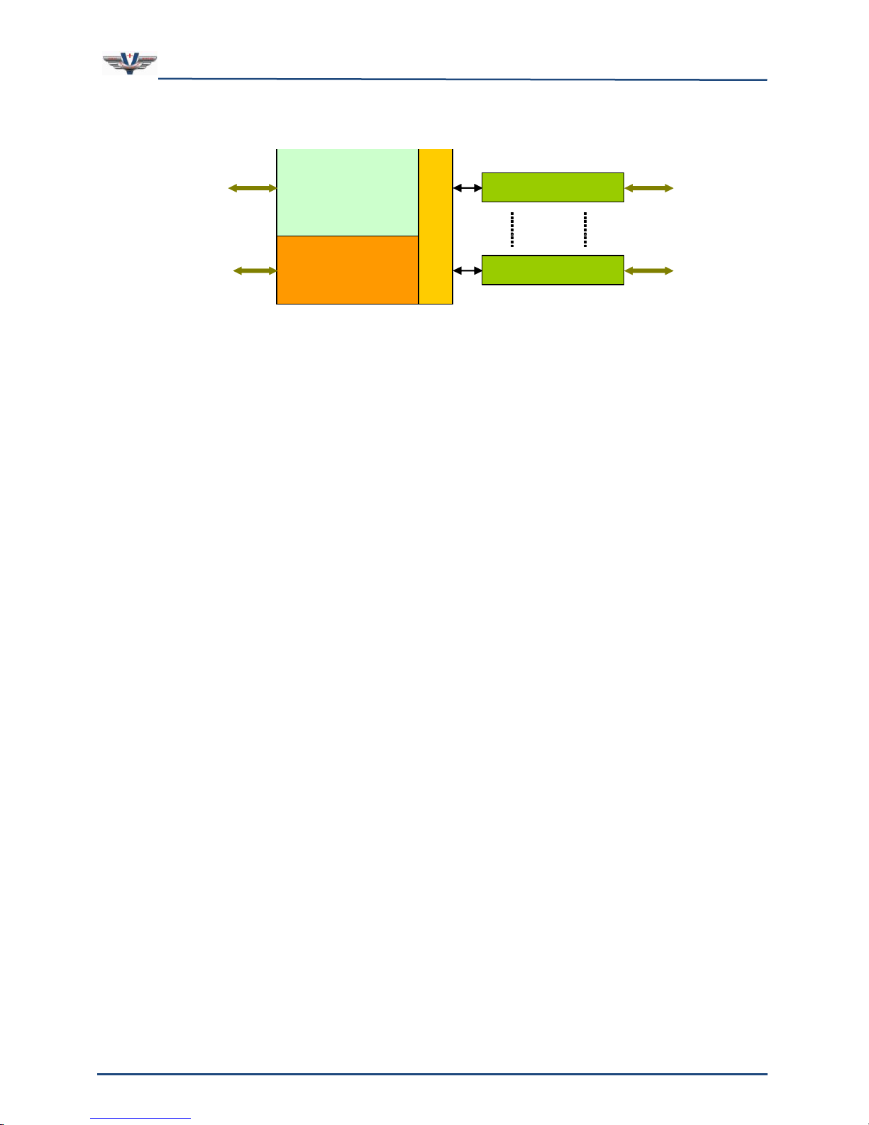
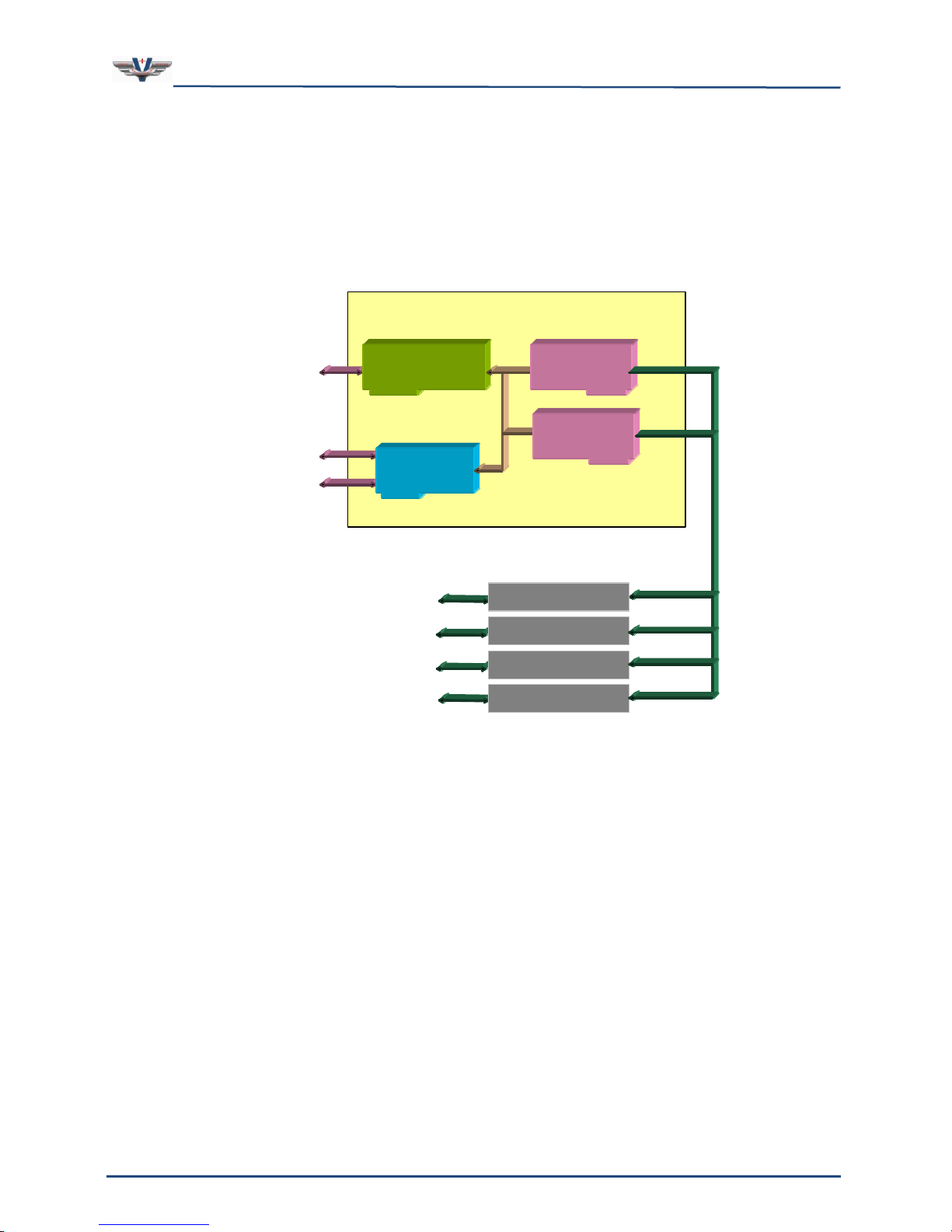
Figure 1 shows a simplified overall view of the system. A CPU powers the system and runs
the visual programming software, V+, which controls all aspects of the system. Audio
signals are connected to the system via ¼” phone plugs on the breakout boxes. Each
breakout box features eight inputs and eight outputs, and one (1) system chassis can
support up to eight breakout boxes for a total of 64 inputs and 64 outputs. The flexibility of
Page 14
SMx Audio System User's Manual, V1.41
SimPhonics, Inc.
Page 14 of 77
Page 14 of 77
Copyright © 2014 SimPhonics, Incorporated, All Rights Reserved
CPU
CPU
BREAKOUT BOXES
I/O Device
Drivers
INTERFACES
BREAKOUT BOXES
AUDIO
S
M
x
D
S
P
the SMX system allows any configuration from one (1) to eight (8) external boxes resulting
in 8 to 64 channels.
Figure 1, SMx System Architecture
The interfaces shown in the figure above refer to a variety of connections that can be one or
more Ethernet connections, and or I/O devices that have their own interfaces specific to
their type. For example, a typical system may have a DIS/HLA Ethernet connection and a
Host Ethernet interface. For now, let’s focus on the audio architecture.
Page 15
SMx Audio System User's Manual, V1.41
SimPhonics, Inc.
Page 15 of 77
Page 15 of 77
Copyright © 2014 SimPhonics, Incorporated, All Rights Reserved
Motherboard
Ethernet
Network
SMx
DSP Card
Computer Chassis
Keyboard,
Monitor,
and Mouse
Network
Interface Card
Analog Inputs
and
Analog Outputs
BREAK-OUT BOX
SMx
DSP Card
BREAK-OUT BOX
BREAK-OUT BOX
BREAK-OUT BOX
3.1 Overall System Block Diagram
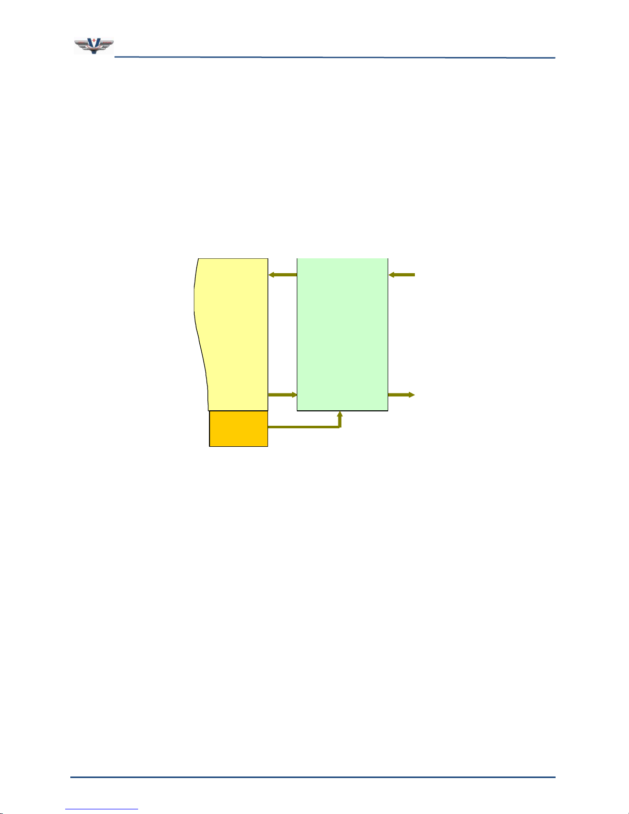
Figure 2 illustrates an overall system block diagram for a standard 32 Channel system. The
delivered components are shown in separate colors. The computer chassis connects to a
Host computer via Ethernet, which commands the system via real-time data. This data
controls a V+ design, which generates sounds via the SMx system and output rack. This
diagram represents our standard 32 Channel configuration, PN: SMx-32-Enn-RM4.
Figure 2, Overall System Block Diagram
Page 16
SMx Audio System User's Manual, V1.41
SimPhonics, Inc.
Page 16 of 77
Page 16 of 77
Copyright © 2014 SimPhonics, Incorporated, All Rights Reserved
AO
AI
WI
WO
Windows
Audio System
(DirectX)
SMx
Super Mixer
V+ SMx
I/O Driver
3.2 SMx Audio System
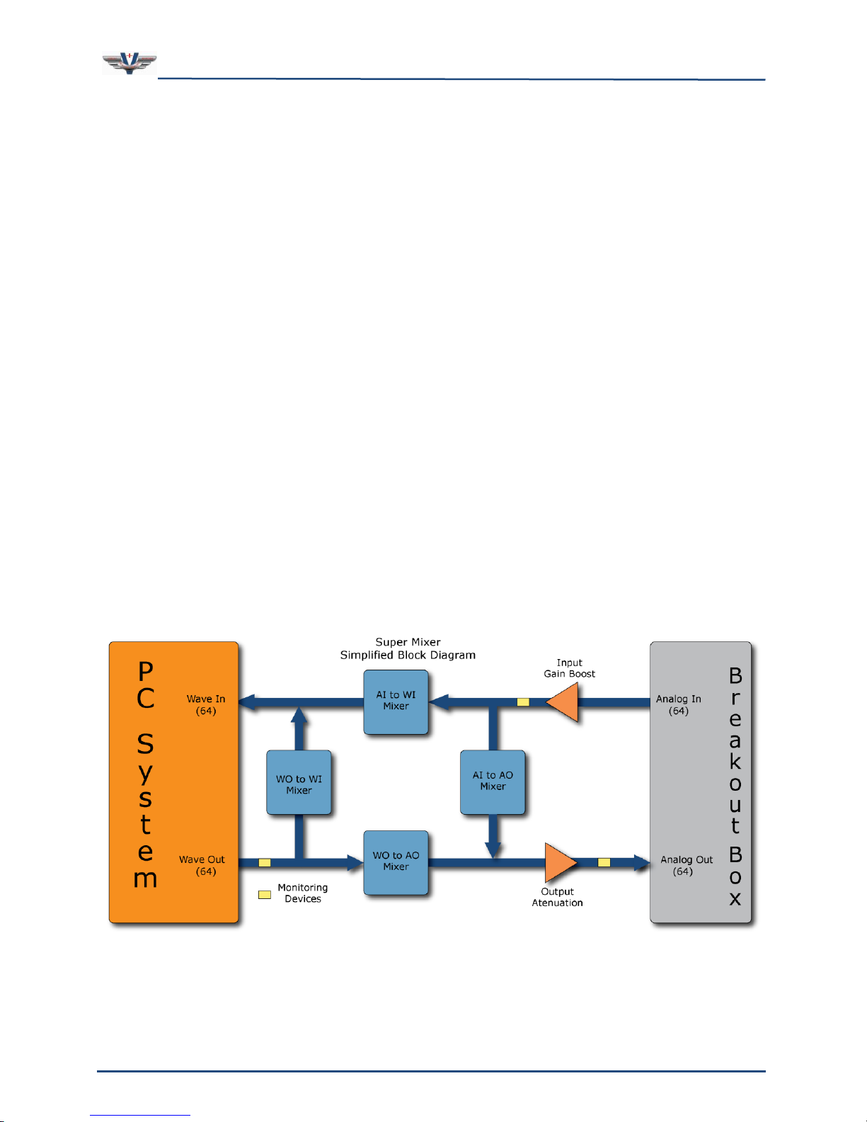
Figure 3 is a top level flow diagram of the AIs to WIs, and WOs to AOs. This is the heart of
the SMx audio system. Analog inputs and outputs flow to and from the Super Mixer, which is
also connected to the Wave inputs and Wave outputs of the Windows operating system. Our
SMx architecture is conceptually the same as an ordinary sound card for Windows, except
that there are many more channels of audio. The Super Mixer is controlled in V+ via the
“SMx Audio System” I/O driver.
The Super Mixer is a kernel level driver embedded within the Windows operating system. It
directly controls the SMx DSP cards which are connected to the breakout boxes. It can route
audio streams in almost any fashion. In order to understand SMx, it is essential to
understand the Super Mixer operation. Each line in the diagram can actually be 64 discrete
channels. Note that breakout boxes are not shown for clarity.
Figure 3, SMx Audio System
Page 17
SMx Audio System User's Manual, V1.41
SimPhonics, Inc.
Page 17 of 77
Page 17 of 77
Copyright © 2014 SimPhonics, Incorporated, All Rights Reserved
3.3 SMx Super Mixer
The Super Mixer is the key to the flexibility of SMx. This is what enables SMx to be used in
applications where normal sound cards cannot. Let’s take a look at how this works. There
are four basic audio signal paths in the Super Mixer (refer to Figure 4):
1. Analog In to Analog Out – Input signals applied to the AIs are routed through the
input gain block, monitored at the AIn metering interface, mixed to AOs by the
Analog In to Analog Out mixer, routed through the output gain block, monitored at
the AOut metering interface and sent to the AOs.
2. Analog In to Wave In – Input signals applied to the AIs are routed through the
input gain block, monitored at the AIn metering interface, mixed to WIs by the
Analog In to Wave In mixer, and sent to the WIs of the Windows audio system.
3. Wave Out to Wave In – WO signals coming from the Windows audio system are
mixed to WIs in the Wave Out to Wave In mixer, and sent to the WIs of the Windows
audio system.
4. Wave Out to Analog Out – WO signals coming from the Windows audio system are
mixed to AOs in the Wave Out to Analog Out mixer, monitored at the WOut metering
interface, routed through the output gain block, monitored at the AOut metering
interface and sent to the AOs.
This mixer is a 64-channel system. That is, all of the lines connecting these mixer
components are 64 channels of audio. Even if your system has less than 64 channels of
physical audio, all 64 signals are mixed. The user can adjust the number of WO and WI
channels that are present in any SMx system. Keep in mind however, more channels means
more processing power needed to perform the Super Mixer calculations. Modern processors
have no problem with a full 64 channel super mixer requiring less than 8 percent of the
overall CPU.
Figure 4, SMx Super Mixer
Page 18
SMx Audio System User's Manual, V1.41
SimPhonics, Inc.
Page 18 of 77
Page 18 of 77
Copyright © 2014 SimPhonics, Incorporated, All Rights Reserved
AI 1
AI 2
AI 64
A
O
1
A
O
2
A
O
6
4
AI 1 to AO 2
Each of the components shown in the figure above are represented in V+ as an I/O device.
Each of these I/O devices is explained further in sections below.
3.4 Individual Mixers
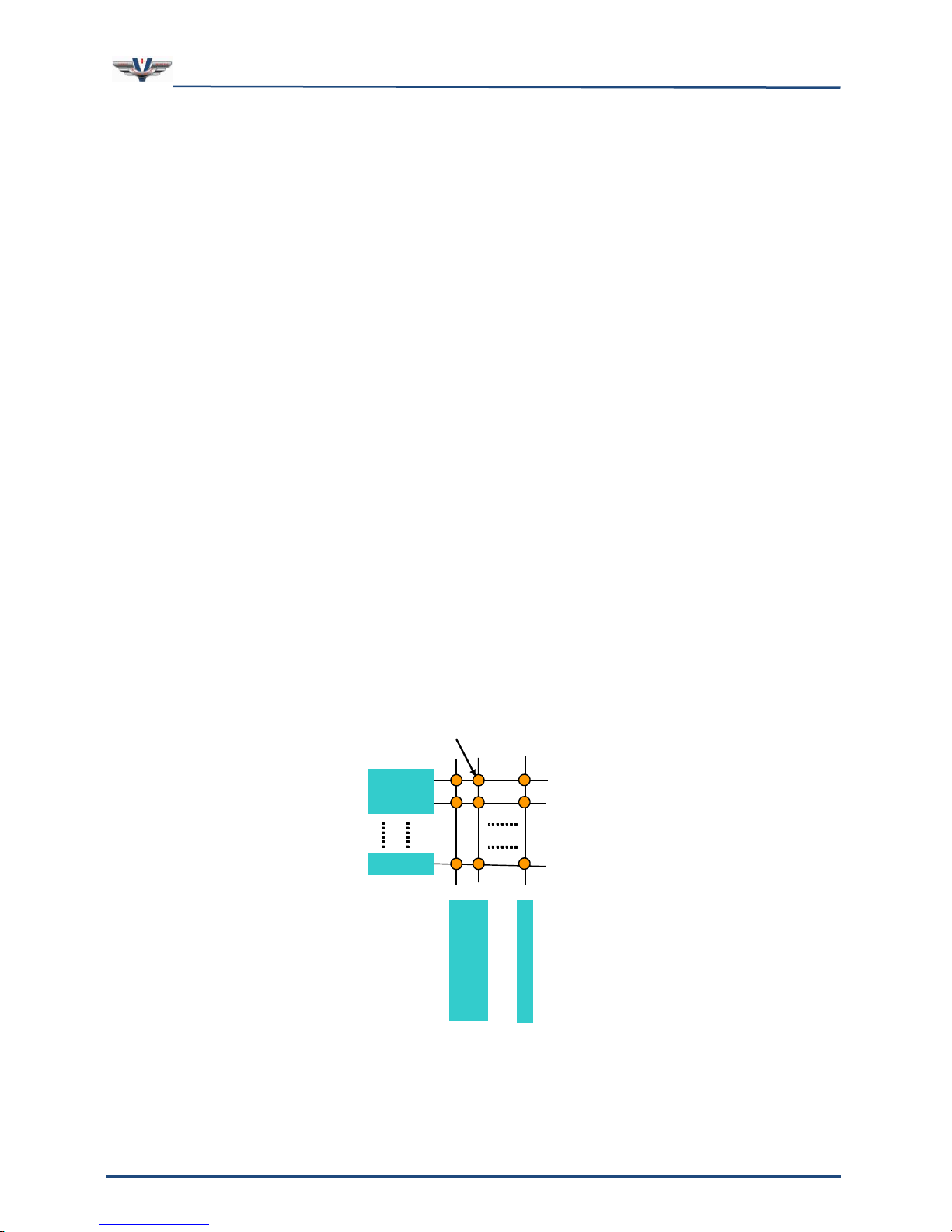
A mixer is a device used to mix audio signals from inputs to outputs. In order to remain
flexible, the mixer must be able to mix any input to any output independently without
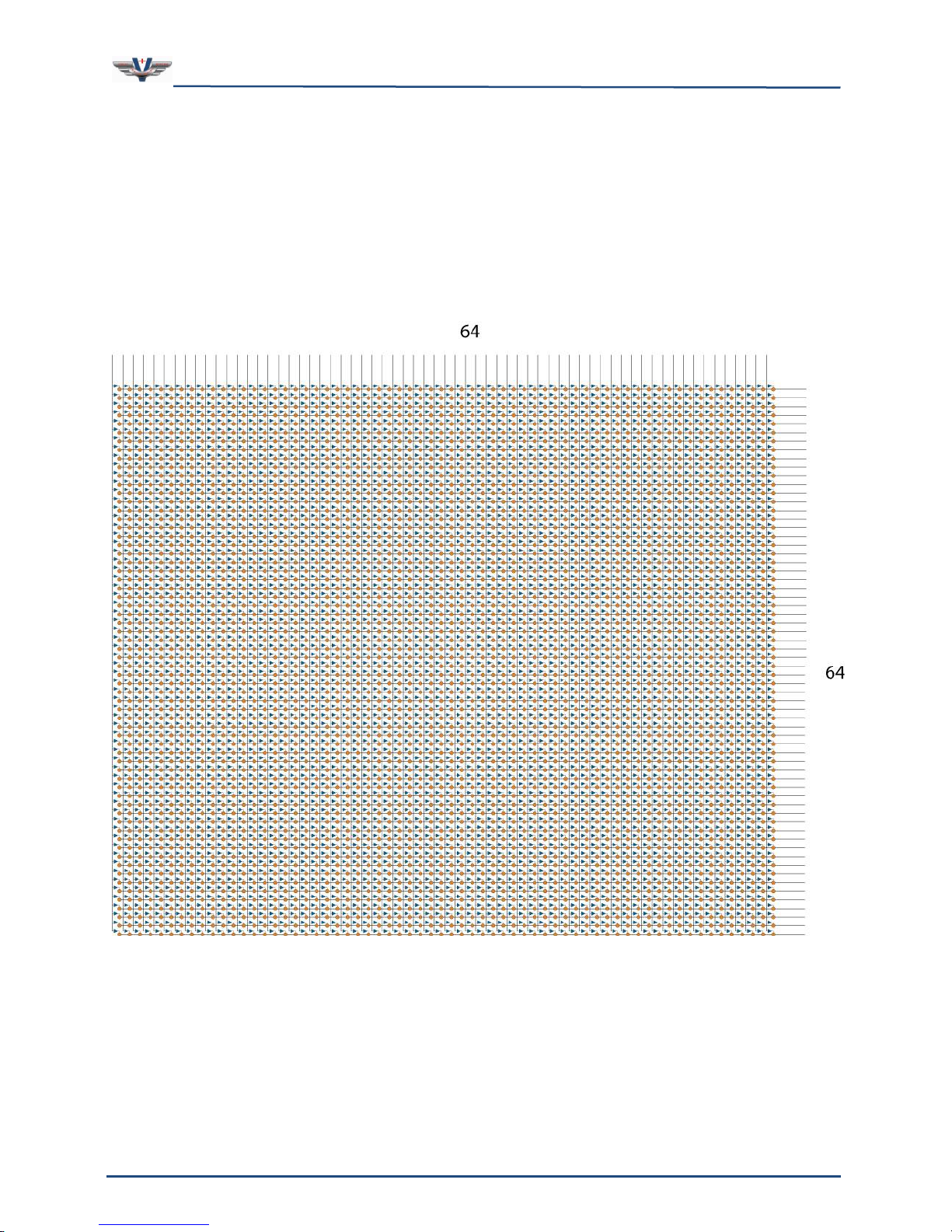
affecting any other inputs or outputs. This is accomplished via a XY matrix of gain controls.
To further understand the generic mixer model, refer to Figure 5 below. The diagram shows
a matrix of lines, 64 horizontal and 64 vertical, with a circle at the intersection of each
horizontal and vertical line. For the sake of this discussion, let each horizontal line represent
an input to the mixer and each vertical line represent an output. The circles at the
intersections, then, would represent the gain values that are used to control the signal flow
from input to output.
The output signal is then computed as the summation of all input signals multiplied by the
respective gain values for that output. Each gain value (as represented by the circles in the
diagram) in the mixer has a corresponding port in V+ that can be given a value from 0.0 to
1.0.
There are four mixers in the SMx Super Mixer (see the tan boxes in Figure 4). The mixer
shown in the figure below is the Analog In to Analog Out Mixer. The mixers and the V+ I/O
devices that control them are discussed later.
As you can see, there a lot of V+ ports needed to control this mixer. In fact there are 64 X
64, or 4,096 ports per mixer, and there are four of them! If this mixer was exposed as a
hardware mixer to Windows XP and there were controls for each gain cell, there would be
over 16,384 controls present on the mixer console.
Figure 5, SMx Mixer Matrix
Page 19
SMx Audio System User's Manual, V1.41
SimPhonics, Inc.
Page 19 of 77
Page 19 of 77
Copyright © 2014 SimPhonics, Incorporated, All Rights Reserved
3.5 Individual Mixer Module
There are four mixer modules in the SMx super mixer and each one contains 4,096 gain
controls that are exposed as a port in V+. The entire SMx super mixer contains 4 X 4,096
or 16,384, + (5) more gain block and meter sections of 64 ports each, resulting in 16,704
V+ ports under CPU control. There is no other mixer like this on planet earth.
Figure 6, Single SMx Mixer Module Showing all 4,096 Gain Controls
Page 20
SMx Audio System User's Manual, V1.41
SimPhonics, Inc.
Page 20 of 77
Page 20 of 77
Copyright © 2014 SimPhonics, Incorporated, All Rights Reserved
Table 1. SMx Physical Specifications
SMx Component
Dimensions (Inches)
Weight (Pounds)
2U System Chassis
3.465H x 19W x 25.6D
31
4U System Chassis
7.00H x 19W x 20.5D
40
SMx Breakout Box
1.5H X 19W X 6D
3
Table 2. SMx Power Requirements
SMx Component
Current
Voltage
2U System Chassis
6 / 3 A
90-264VAC (Auto Switching), 47-63Hz
4U System Chassis
10 / 5 A
100- 240 VAC (Auto Switching), 47-63Hz
SMx Breakout Box
1.5 / .75A
90-264VAC (Auto Switching), 47-63Hz
Table 3. Operating and Storage Conditions
Category
Operating
Storage
Temperature
0°C to 40°C
-20°C to 60°C
Altitude
0 to 10,000 Feet
0 to 40,000 Feet
Humidity
20% to 90% (Non-condensing)
5% to 95% (Non-condensing)
4 Hardware
4.1 Specifications
Physical
All components shown in the Table 1 are standard 19” EIA rack-mountable units.
Power Requirements
All components shown in Table 2 are designed to operate from US or European power
systems. The SMx Breakout Box power supply is CE certified.
Operating and Storage
Table 3 lists the operating and storage conditions for the SMx Audio System. Note: These
specifications are for the SMx system without a keyboard, monitor and mouse.
Page 21
SMx Audio System User's Manual, V1.41
SimPhonics, Inc.
Page 21 of 77
Page 21 of 77
Copyright © 2014 SimPhonics, Incorporated, All Rights Reserved
Table 4. Electrical Characteristics
Item
Volts
Input
13.1 V Peak, 9.26 Vrms
Output
13.1 V Peak, 9.26 Vrms
Table 5. Audio Performance Specifications
Item
Specification
Analog Inputs (8 Single Ended TS)
Frequency Response
10 Hz – 22 kHz, ±0.25dBA
Dynamic Range
110 dBA (24 bit)
THD+n
<0.001%, 20 Hz–22 kHz, A-weighted
Nominal Input Level
+4 dBu
Maximum Input Level
+22 dBu
Input Impedance
10 K
Analog Outputs (8 Single Ended)
Frequency Response
10 Hz – 22 kHz, ±0.25dBA
Dynamic Range
116 db
THD+n
<0.002%, 20 Hz–22 kHz, A-weighted
Nominal Output Level
+4 dBu
Maximum Output Level
+22 dBu
Crosstalk
> 81dB of rejection across a frequency
range of 20 Hz to 20 KHz with a -10 dBv
input sine wave signal.
4.2 Electrical Characteristics
The voltages in Table 4 represent full-scale 24 bit conversions with 0dB boost and maximum
gains of 1.0 on the Super Mixer controls. Boost values are in +6dB increments, up to
+60dB.
4.3 Audio Performance
Audio performance specifications are provided in Table 5.
4.4 Transport Delay
The SMx was designed to minimize transport delays between input and output audio
through the use of a Super Mixer. The delay from analog input to analog output using the
Analog Input to Analog Output Mixer device is less than 6 milliseconds. More detail on the
Super Mixer is provided below.
4.5 Reliability and Maintainability
SimPhonics has calculated and produced a Reliability and Maintainability (R&M)
documentation for the SMX system. Our document contains information about the SMx
Mean Time Between Failures (MTBF) and Mean Time To Repair (MTTR). This information is
used to predict how long repairs and maintenance tasks will take in the event of a system
failure.
Page 22
SMx Audio System User's Manual, V1.41
SimPhonics, Inc.
Page 22 of 77
Page 22 of 77
Copyright © 2014 SimPhonics, Incorporated, All Rights Reserved
Table 6, Chassis Options
Chassis
Configuration
Maximum SMx
DSP Cards
Maximum Physical
Channels Per Chassis
Maximum SMx
Breakout Boxes
Laptop with 1 PCMCIA Card
1
16 2 Laptop with 2 PCMCIA Cards
2
32 4 Mid-Tower Desktop
4
64 8 2U Rack Mount
2
32 4 4U Rack Mount
4
64
8
For more information, go to our website to download the SMx Reliability and Maintainability
Predictions document.
4.6 CPU Chassis
The computer system for SMx can be ordered as a laptop, desktop, or rack-mounted unit.
Most applications will use a rack-mounted unit. Table 6 shows the relationship between the
various types of physical CPU’s and the number of breakout boxes that may be used.
SimPhonics also provides a PCMCIA card for the SMx system in order to use a laptop as a
CPU for the SMx system. Up to two of these cards can be used, providing up to 32 channels.
It is unlikely that a laptop would be used to drive 32 audio channels in a given application;
however a laptop could be used as a development system for SMx applications.
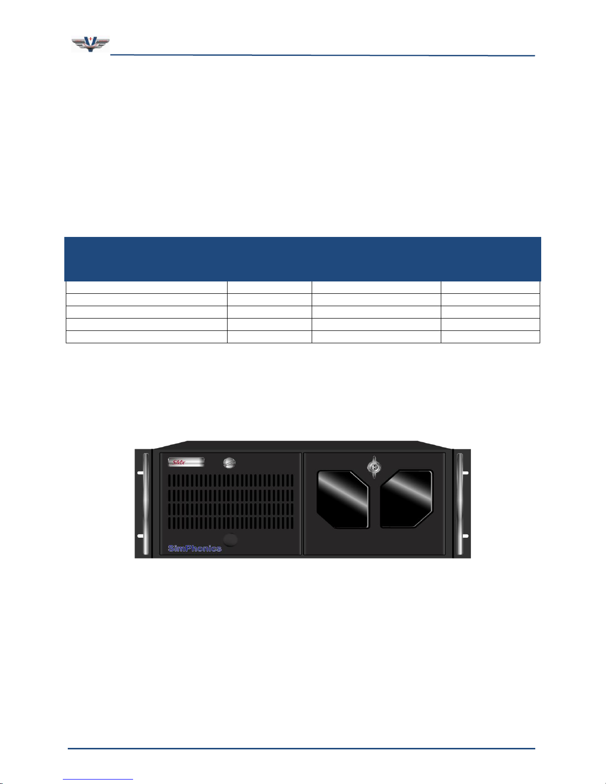
Any typical SMx SOUND/COMM system utilizes a 4U high 19-inch rack-mountable chassis,
with an ATX style power supply. Depending on the user’s application, SimPhonics can
deliver 2U or 4U rack-mount style chassis; 4U or 6U passive backplane chassis, desktop, or
laptop units. (The SMx system, when integrated and designed for Sound, COMM, Voice, and
I/O, for example, fits into a single 4U high chassis).
Figure 7, Typical SMx PC Chassis
Page 23
SMx Audio System User's Manual, V1.41
SimPhonics, Inc.
Page 23 of 77
Page 23 of 77
Copyright © 2014 SimPhonics, Incorporated, All Rights Reserved
Table 7. SMx System Minimum Performance Characteristics
Computer Component
Specifications
Processor
Intel® CoreTM i7-3770 3.4GHz LGA1155 22nm (4 cores/8 threads)
RAM
8GB DDR3 PC3-12800 1600Mhz Cas Latency 11
Number of PCI Slots
5 or More
Hard Drive
500GB SATA III 6Gbps 7200rpm
Optical Drive
CD/DVD-RW SATA
Video
Intel® HD Graphics 4000 (built into the processor)
Ethernet
2 Gigabit Ethernet Ports
4.7 Motherboard and Processor
SimPhonics uses all of the latest technology Intel based processors and motherboards in our
SMx computer systems. The current delivered i7 motherboard has two 240-pin DDR3 DIMM
sockets supporting up to 16GB of RAM and are equipped with a minimum of five (5) PCI
slots. All normal I/O ports such as video, Ethernet, PS/2 and USB ports are integrated to the
motherboard’s I/O backpane. Table 7 below summarizes the minimum processing capability
of the current SimPhonics SMx computer configuration.
Additional quad-port Ethernet cards and Data Acquisition (DAQ) cards can be configured
into the system upon request. SimPhonics has numerous I/O device drivers available
including NI DAQ devices so that interoperates with V+ seamlessly.
SimPhonics uses only genuine Intel processors in systems since some software utilizes the
latest DirectX instructions for real-time high performance audio applications. Also, the Intel
processor features several high accuracy-timing registers that may not be available on other
processors.
4.8 Diskless Operation
SMx CPU chassis provided by SimPhonics support diskless boot operation via an Ethernet
connection. The motherboard BIOS supports the Intel Preboot Execution Environment (PXE).
The Network Interface Card (NIC) chipset, whether on board or installed in a PCI slot, are
Wired-For-Management (WFM) qualified. Since there are numerous products which support
diskless operation, the exact nature of the diskless implementation is application specific.
Page 24
SMx Audio System User's Manual, V1.41
SimPhonics, Inc.
Page 24 of 77
Page 24 of 77
Copyright © 2014 SimPhonics, Incorporated, All Rights Reserved
Table 8 Cable Limitations
From
To
Part No.
Description
Max
Length
System Chassis
AC Outlet
Vendor
Supplied
Power Cord
6 feet
System Chassis
Breakout Box
(Master)
SM4038-XX
SMx Serial Cable
100 feet
Breakout Box
AC Outlet
Vendor
Supplied
Power Cord
6 feet
Breakout Box
(Master)
Breakout Box
(Slave)
SM4F01-XX
SMx Plastic Fiber Optic
Cable
50 feet
Breakout Box
(Master)
Breakout Box
(Master)
SM4039-XX
SMx Sync Cable
100 feet
4.9 SMX Breakout box
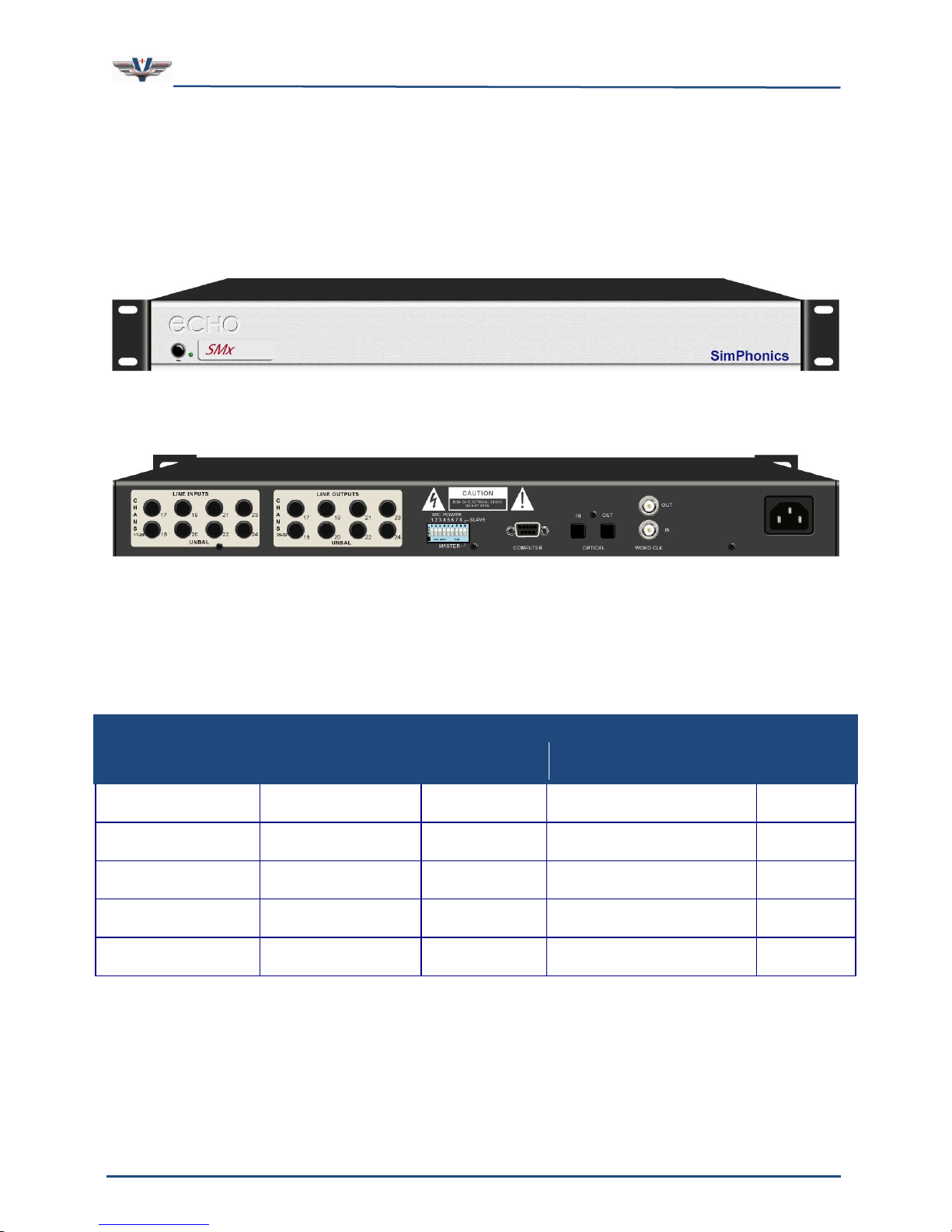
Figure 8 and Figure 9 below depict the front and rear views respectively of an SMx Breakout
Box, part number SMXBOB-10. Every Breakout Box is identical and can be configured to be
either a Master or a Slave. The LINE INPUTS and LINE OUTPUTS labels are separate parts
and can be replaced to denote the correct channel numbers.
Figure 8, SMXB0B-10 Front View
Figure 9, SMXB0B-10 Rear View
4.10 Cable Limitations
Table 8 outlines physical length limitations for system hardware cabling.
Page 25
SMx Audio System User's Manual, V1.41
SimPhonics, Inc.
Page 25 of 77
Page 25 of 77
Copyright © 2014 SimPhonics, Incorporated, All Rights Reserved
4.11 Recommended Mating Connectors
The following Switchcraft ¼” mono mating connectors are recommended when connecting
to SMx single-ended input and output audio channels:
Switchcraft ¼” Phone Plug (black), PN: 250
Switchcraft ¼” Phone Plug (red), PN: 255
We further recommend that any Buyer interface cables use Red handled connectors for all
Inputs, and Black handled connectors for all Outputs. (Colored heat shrink can also be used
for Input/output identification purposes.)
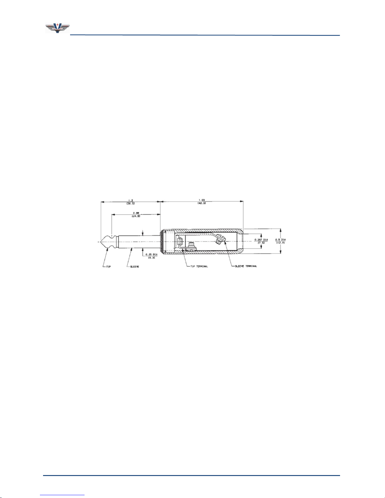
Note that these Switchcraft brand connector handles are cylindrical in nature providing a
consistent outside diameter (OD) from top to bottom (see Figure 10). This allows multiple
connectors to be plugged into the SMx without interference. Many other manufacturers or
brands of ¼” mono plugs have conical handles where the OD gets larger as it gets closer to
the connector. This "larger" diameter handle causes interference when plugged in side by
side on an SMx breakout box and therefore CANNOT be used. The maximum diameter of a
Switchcraft plug is ½” as show below. This is the maximum diameter for a connector to plug
into a SMx breakout box.
Figure 10, Switchcraft Plug Physical Dimensions
Another reason these Switchcraft parts are recommended is the head of the plug has more
of a tip and is smooth. Many are flat on top, flat on the sides, and/or have sharp edges –
they do not plug in or mate as efficiently.
Page 26
SMx Audio System User's Manual, V1.41
SimPhonics, Inc.
Page 26 of 77
Page 26 of 77
Copyright © 2014 SimPhonics, Incorporated, All Rights Reserved
4.12 SMX PCI DSP Card
The SMx audio interface is used for the input and output of analog sounds and voice, such
as intercom, aircraft/avionics tones, and radio communications in Simulator Subsystems.
Contrary to standard PC audio cards, which provide one set of stereo inputs and outputs (2
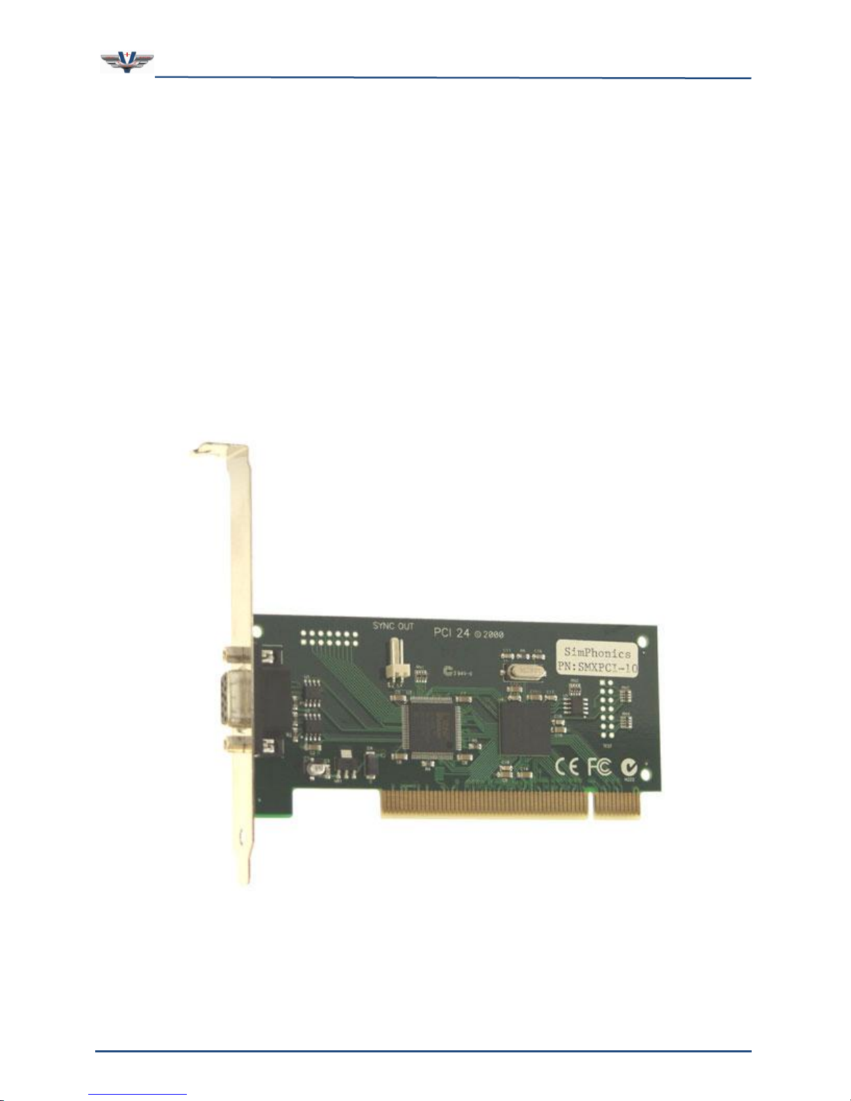
input, 2 output channels), the PCI based SMx DSP card, shown in Figure 11, is capable of
processing up to 16 analog audio inputs and 16 analog audio outputs. The composite audio
input and output signals are sent to and from the audio card via a serial cable to the 19”
rack-mounted breakout boxes, where the signals are combined and separated. Located on
the rear of the boxes are the necessary ¼” mono input and output connections which
connect directly to the analog equipment (microphones, headphones, amplifiers, etc).
The SMx DSP card is a simple 32-bit PCI card. Up to four of these cards may be used in an
SMx system for up to 64 channels of audio. Each card is responsible for 16 channels. The
cards are synchronized via an external BNC cable on the external boxes. This sync cable is
connected from the first card’s breakout box master to the next card’s external breakout box
master, to the next card’s breakout box master, etc. More details on the synchronization
connections are provided below.
The order of channels is dictated by the order that the cards are plugged into the PCI bus.
On most motherboards, PCI slot 0 is located next to the AGP slot, or closer to the CPU. The
Figure 11, SMx DSP Card
Page 27

SMx Audio System User's Manual, V1.41
SimPhonics, Inc.
Page 27 of 77
Page 27 of 77
Copyright © 2014 SimPhonics, Incorporated, All Rights Reserved
cards do not have to be located in adjacent slots however. There are no jumpers on the DSP
card as this is a fully plug and play compliant card.
4.13 Simulated Hardware
If the SMx Audio System I/O device for V+ is loaded with no SMx DSP present on the
machine, the I/O device will sense this situation, and simulate the hardware. This is
important, since V+ can be used to create and or edit SMx V+ designs even though the SMx
hardware is not present.
4.14 Sound Cards
You can use additional sound cards with the SMx. However, Windows XP limits the number
of stereo (two channel) sound cards that can be used to 32, which is 64 channels. If a 64
channel SMx system is installed, no additional sound cards can be used. The additional
sound card may in fact cause the 64 channel SMx system not to work at all.
If you are using additional sound cards, make sure you set the “sample rate conversion
quality” to its highest setting (see below).
Note: When less than a 64 channel SMx system is installed, ensure that you use a sound
card with a WDM driver.
4.14.1 Setting the Sample Rate Conversion Quality
If an additional sound card is used with SMx, it is mandatory to set the “sample rate
conversion quality” to the highest setting. To set the sample rate conversion quality, do the
following:
1. Click Start, select Settings, select Control Panel.
2. Double-click the Sounds and Audio Devices icon.
3. Select the Audio tab.
4. If the Advanced button(s) are not highlighted, click OK. Close the control panel,
restart the computer and skip the remaining steps. Otherwise, in the Sound
playback section, click the Advanced button.
5. Select the Performance tab.
6. Make sure the Hardware acceleration slider is set to Full.
7. Make sure the Sample rate conversion quality slider is set to Best.
8. Click OK.
9. Click OK.
10. Close the Control Panel.
11. Restart the computer.
Page 28
SMx Audio System User's Manual, V1.41
SimPhonics, Inc.
Page 28 of 77
Page 28 of 77
Copyright © 2014 SimPhonics, Incorporated, All Rights Reserved
4.14.2 Controlling the Sound Cards
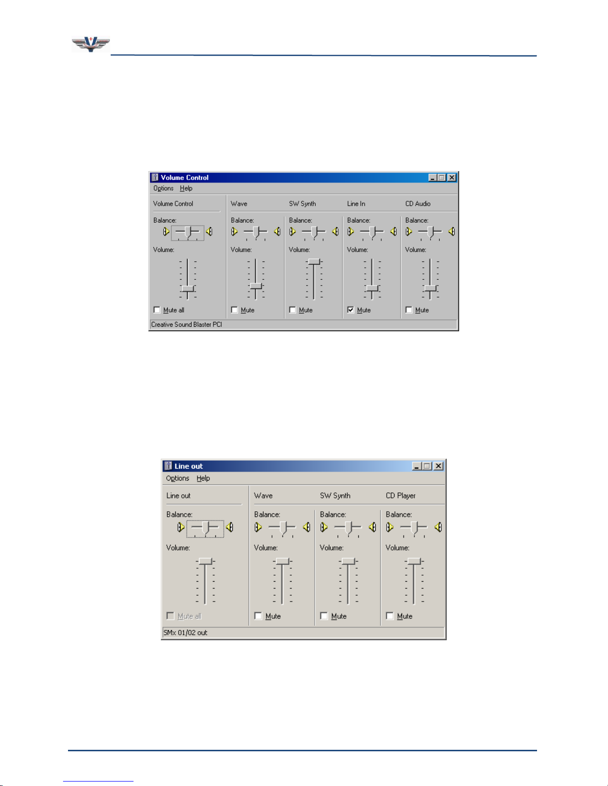
Most sound cards for the PC expose a set of controls to Windows that allow Windows to
manipulate their mixer. This is called the Windows Audio Mixer, and is controlled via the
Volume Control panel. For example, a Creative sound Blaster PCI card exposes a Volume
Control panel that looks like Figure 12 below. Note the name of the device in the bottom left
corner.
Figure 12, Creative Sound Blaster PCI Card Control Panel
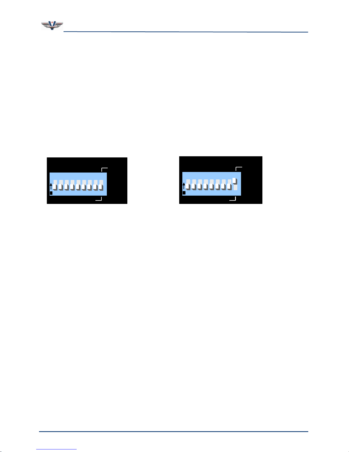
The SMx Super Mixer does not reveal its controls to the Windows Audio Mixer environment.
However, Windows automatically exposes some of these controls. Figure 13 shows the
controls which are displayed for the playback section of each SMx device. The controls for
Line out, SW Synth, and CD Player have no effect. However, the Wave control does. Always
leave this control at its maximum position (default) as shown. Decreasing this gain will
decrease the amplitude of the Wave Out signals before these signals are introduced into the
super mixer.
Figure 13, SMx Playback Controls Exposed by Windows
If you are using another sound card along with the SMx system, V+ provides a way to
manipulate these controls within a V+ application. This is accomplished using the “Windows
Page 29

SMx Audio System User's Manual, V1.41
SimPhonics, Inc.
Page 29 of 77
Page 29 of 77
Copyright © 2014 SimPhonics, Incorporated, All Rights Reserved
Audio Mixer I/O Device” which is a topic discussed in the V+ Programming System User
Manual.
4.15 Power-up and down Sequence
AC power should be applied to each of the SMx components simultaneously or within a few
seconds of each other.
4.15.1 Powering Up the System
Turn the SMx breakout box(s) power on first. Power should be applied to all the breakout
boxes within a few seconds of each other.
Apply power to the computer chassis.
Note: The SMx system does not work properly if it is not powered up in the correct
sequence! If you mistakenly power up the computer before the breakout boxes, simply
reboot the computer (with the breakout boxes turned on).
4.15.2 Powering Down the System
When powering off the SMx system:
1. Shut down the SMx system CPU first, using the shutdown feature of the operating
system.
2. Remove power to the external SMx chassis.
Note: If power is removed from one of the breakout boxes while the SMx CPU system is
running, the SMx CPU system will have to be rebooted.
5 SMx System Interconnect
All of the SMx interconnection cables are supplied with the system, and consist of the PCI
card to breakout box, fiber optic interconnect, and BNC sync cables along with the power
cords for the breakout boxes. If any of the interconnect cables are not connected properly
the system will not function correctly.
The SMx internal PCI card connects to the breakout boxes via a serial cable with DB9
connectors.
The sync cable synchronizes the sampling clocks among the PCI cards installed in your
system. SMx will not work without this sync cable, and the driver software will remind you
of this if you attempt to run the system without it. The sync cable connects to the sync
output of the first master box to the input sync of the next master box, etc.
Toslink fiber optic cables connect a master breakout box to its slave. Two cables are used:
master output to slave input, and slave output to master input.
Page 30
SMx Audio System User's Manual, V1.41
SimPhonics, Inc.
Page 30 of 77
Page 30 of 77
Copyright © 2014 SimPhonics, Incorporated, All Rights Reserved
l
MIC POWER
1 2 3 4 5 6 7
8
SLAVE
MASTER
O
N
1 2 3 4 5 6 7 8 9
CTS
206-9
T108
Switch 9 in the
“master”
position
l
MIC POWER
1 2 3 4 5 6 7
8
SLAVE
MASTER
O
N
1 2 3 4 5 6 7 8 9
CTS
206-9
T108
Switch 9 in the
“slave”
position
5.1 SMx Breakout Box DIP Switch Settings
The switch settings shown below are the DIP switches located on the rear of the SMx
breakout box(s). These switches are used to select Phantom Power, and are also used to
select Master/Slave box position within the system design.
5.1.1 Master/Slave DIP Switch
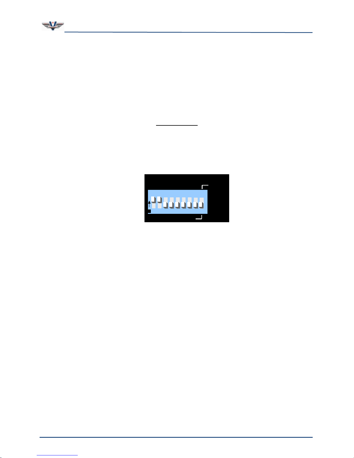
Each PCI card connects to the master breakout box, which in turn connects to an additional
breakout slave box if more than eight channels are used. Therefore each PCI card can
connect up to two boxes, the master and the slave. Each breakout box is assigned a master
or a slave by setting a DIP switch on the back of the unit (see Figure 14). When switch 9 is
moved to the “down” position, the box is in MASTER mode. When switch number 9 is moved
to the “up” position, the box is in the SLAVE mode.
Figure 14, Breakout Box Master/Slave Dip Switch
Page 31
SMx Audio System User's Manual, V1.41
SimPhonics, Inc.
Page 31 of 77
Page 31 of 77
Copyright © 2014 SimPhonics, Incorporated, All Rights Reserved
l
MIC POWER
1 2 3 4 5 6 7
8
SLAVE
MASTER
O
N
1 2 3 4 5 6 7 8 9
CTS
206-9
T108
Switches 1 & 2
phantom power
turned on.
5.1.2 Phantom Power Switches
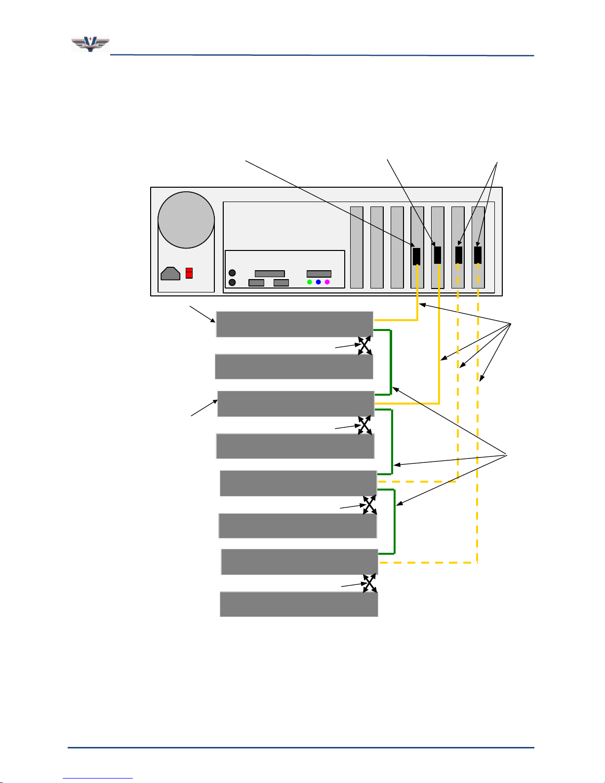
The SMx system is capable of connecting to phantom power type microphones, or phantom
powered mic preamps. Each channel features a phantom power option set by a DIP switch
on the rear of each chassis. Most general aviation style headset microphones utilize
phantom power and will not work without it. If the switch is in the ON position, a +15Vdc
signal is applied back down the input. The current is limited by a 130ohm resistor used for
dropping the voltage; ideally to 7.5Vdc and the AC signal rides on the DC level.
The SMx uses a 130ohm pull-up resistor to +15VDC. For those applications using phantom
power check to ensure that this is compatible with your microphone preamplifier.
IMPORTANT!
Do not turn on the phantom power unless you are sure that a microphone pre-amp is
connected to the corresponding input connector. Otherwise, the phantom power can cause
damage to electronic equipment that is connected to the input. To select Phantom Power
(MIC POWER ON), DIP switches 1-8 should be positioned in the “up” or top of the slot
position (for the corresponding input channel(s) on your box). Figure 15 portrays phantom
power switches 1 and 2 turned on with switches 3 through 8 turned off.
Figure 15, Breakout Box Phantom Power Switches
Note: If the SMx box is for any group of channels, other than 1-8, the lowest MIC POWER
number will always correspond with the lowest channel number; the next lowest MIC Power
switch with correspond with the next lowest channel number, etc.
Page 32
SMx Audio System User's Manual, V1.41
SimPhonics, Inc.
Page 32 of 77
Page 32 of 77
Copyright © 2014 SimPhonics, Incorporated, All Rights Reserved
SMX PCI
CARDS
Slot 7
Slot 6
Slot 5
Slot 4
Slot 3
Slot 2
Slot 1
SERIAL
CABLES
SYNC
CABLES
SLAVE – BREAKOUT BOX
CHANNELS 9-16
MASTER – BREAKOUT BOX
CHANNELS 1-8
FIBER OPTIC CABLES
Note: The SMx PCI card with the lowest slot number (4) is connected to the Master – Breakout Box with the lowest
channel numbers (1-8). The SMx PCI card with the next lowest slot number (5) is connected to the Master – Breakout box
with the next lowest channel numbers (17-24). etc.
SLAVE – BREAKOUT BOX
CHANNELS 25-32
MASTER – BREAKOUT BOX
CHANNELS 17-24
SLAVE – BREAKOUT BOX
CHANNELS 41-48
MASTER – BREAKOUT BOX
CHANNELS 33-40
SLAVE – BREAKOUT BOX
CHANNELS 57-64
MASTER – BREAKOUT BOX
CHANNELS 49-56
FIBER OPTIC CABLES
FIBER OPTIC CABLES
FIBER OPTIC CABLES
SMX PCI CARD WITH LOWEST
SLOT NUMBER (4)
SMX PCI CARD WITH NEXT
LOWEST SLOT NUMBER (5)
MASTER BREAKOUT BOX
WITH LOWEST CHANNEL
NUMBERS (1-8)
MASTER BREAKOUT BOX
WITH NEXT LOWEST
CHANNEL NUMBERS (17-24)
5.2 Connecting SMx Cards to SMx Master Boxes
Using Serial Cables, connect SMx cards with lower PCI slot numbers to SMx master boxes
with lower channel numbers (see Figure 16). Lower slot numbers are closer to the left side
of the chassis facing the rear of the chassis.
Figure 16, Connecting SMx Cards to Master Boxes
Page 33
SMx Audio System User's Manual, V1.41
SimPhonics, Inc.
Page 33 of 77
Page 33 of 77
Copyright © 2014 SimPhonics, Incorporated, All Rights Reserved
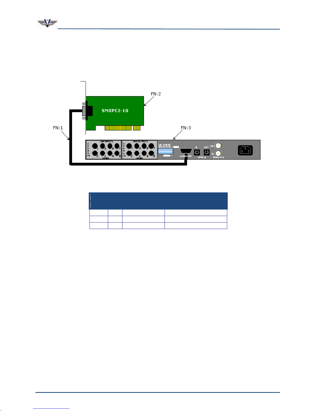
Table 9, 8 Channel SMx System Parts List
Qty
FN
Part No.
Description
1 1 SM4038- xx
SMx Serial Cable
1 2 SMXPCI-10
SMx PCI Card
1 3 SMXB0B-10
SMx Breakout Box
5.3 8 Channel System
Figure 17 depicts an 8 channel SMx system connection diagram. Table 9 provides the list of
parts for this configuration.
Figure 17, 8 Channel SMx System Connection Diagram
Page 34
SMx Audio System User's Manual, V1.41
SimPhonics, Inc.
Page 34 of 77
Page 34 of 77
Copyright © 2014 SimPhonics, Incorporated, All Rights Reserved
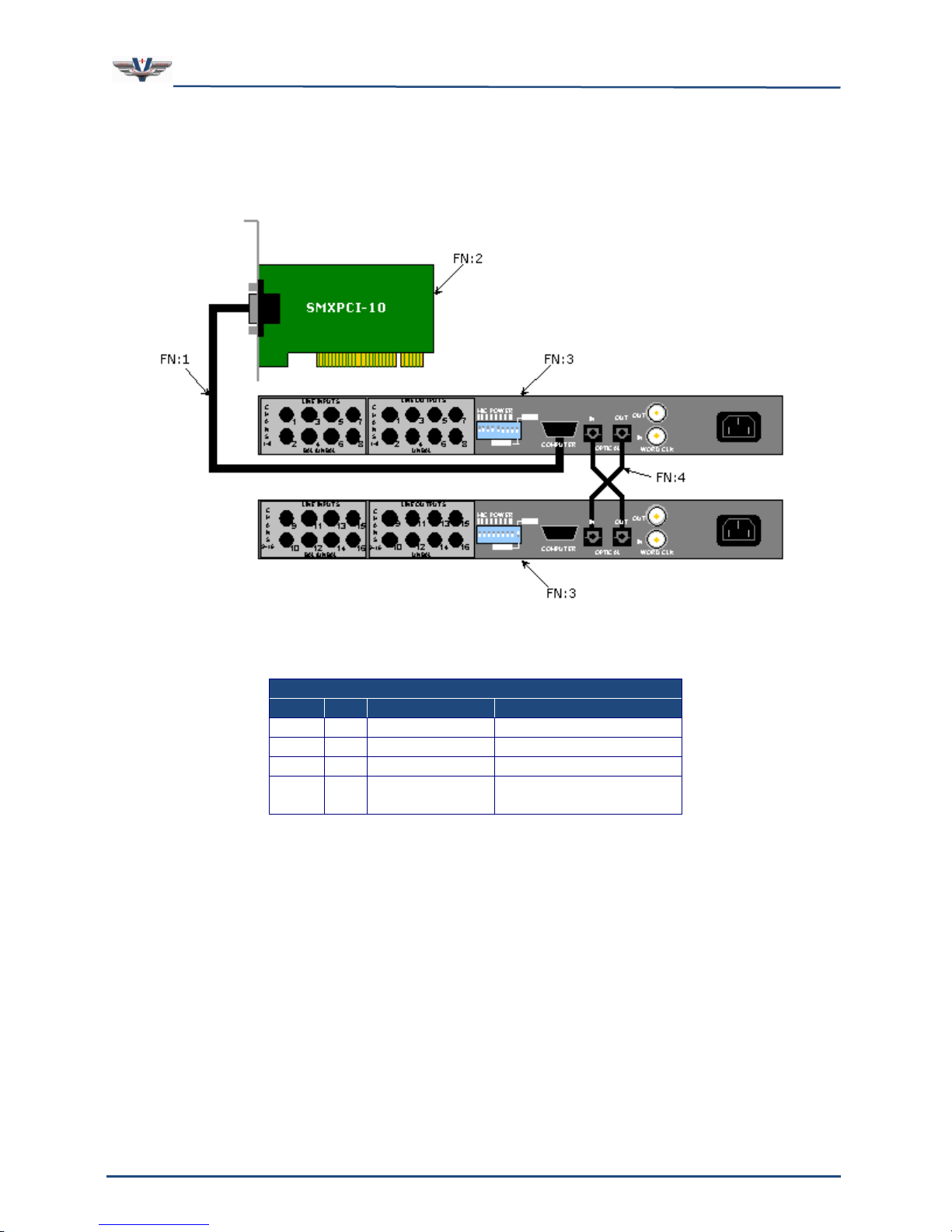
Table 10. 16 Channel SMx System Parts List
Qty
FN
Part No.
Description
1 1 SM4038-xx
SMx Serial Cable
1 2 SMXPCI-10
SMx PCI Card
2 3 SMXB0B-10
SMx Breakout Box
2 4 SM4F01-xx
SMx Plastic Fiber
Optic Cable
5.4 16 Channel System
Figure 18 depicts an 16 channel SMx system connection diagram. Table 10 provides the list
of parts for this configuration.
Figure 18, 16 Channel SMx System Connection Diagram
Page 35
SMx Audio System User's Manual, V1.41
SimPhonics, Inc.
Page 35 of 77
Page 35 of 77
Copyright © 2014 SimPhonics, Incorporated, All Rights Reserved
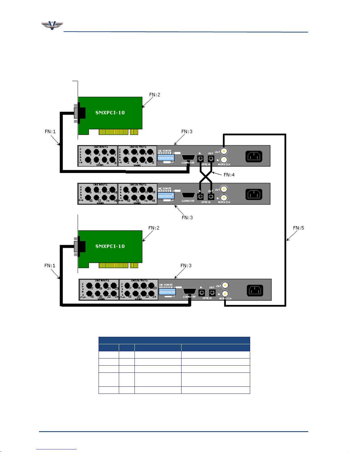
Table 11. 24 Channel SMx System Parts List
Qty
FN
Part No.
Description
2 1 SM4038-xx
SMx Serial Cable
2 2 SMXPCI-10
SMx PCI Card
3 3 SMXB0B-10
SMx Breakout Box
2 4 SM4F01-xx
SMx Plastic Fiber
Optic Cable
1 5 SM4039-xx
SMx Sync Cable
5.5 24 Channel System
Figure 19 depicts an 24 channel SMx system connection diagram. Table 11 provides the list
of parts for this configuration.
Figure 19, 24 Channel SMx System Connection Diagram
Page 36
SMx Audio System User's Manual, V1.41
SimPhonics, Inc.
Page 36 of 77
Page 36 of 77
Copyright © 2014 SimPhonics, Incorporated, All Rights Reserved
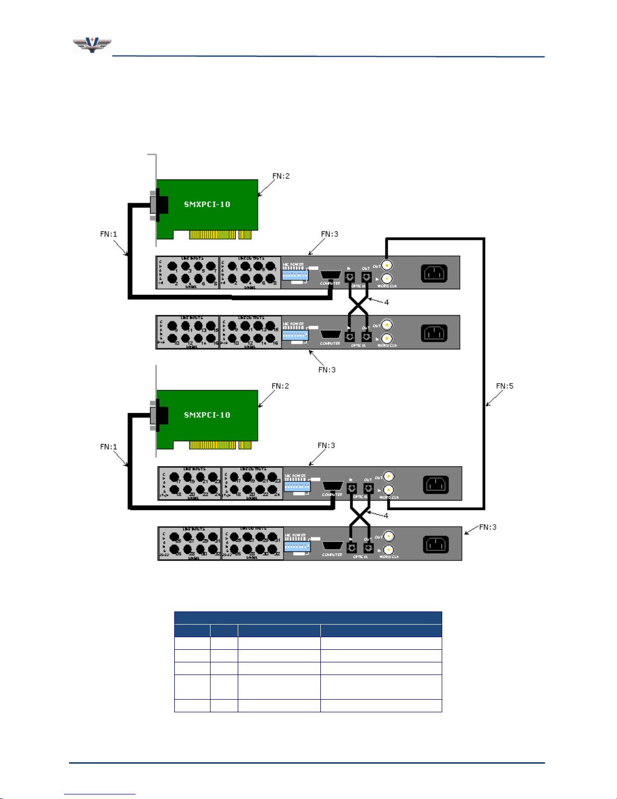
Table 12. 32 Channel SMx System Parts List
Qty
FN
Part No.
Description
2 1 SM4038-xx
SMx Serial Cable
2 2 SMXPCI-10
SMx PCI Card
4 3 SMXB0B-10
SMx Breakout Box
4 4 SM4F01-xx
SMx Plastic Fiber
Optic Cable
1 5 SM4039-xx
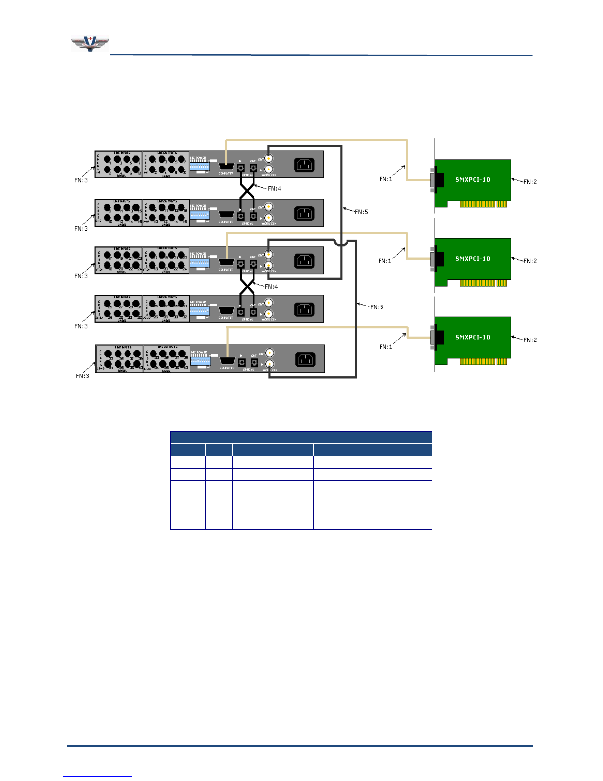
SMx Sync Cable
5.6 32 Channel System
Figure 20 depicts an 32 channel SMx system connection diagram. Table 12 provides the list
of parts for this configuration.
Figure 20, 32 Channel SMx System Connection Diagram
Page 37
SMx Audio System User's Manual, V1.41
SimPhonics, Inc.
Page 37 of 77
Page 37 of 77
Copyright © 2014 SimPhonics, Incorporated, All Rights Reserved
Table 13. 40 Channel SMx System Parts List
Qty
FN
Part No.
Description
3 1 SM4038-xx
SMx Serial Cable
3 2 SMXPCI-10
SMx PCI Card
5 3 SMXB0B-10
SMx Breakout Box
4 4 SM4F01-xx
SMx Plastic Fiber
Optic Cable
2 5 SM4039-xx
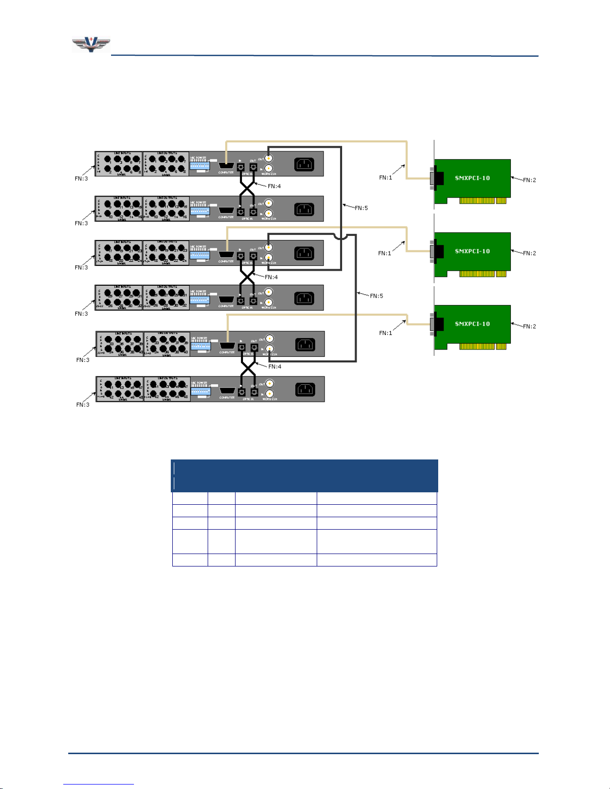
SMx Sync Cable
5.7 40 Channel System
Figure 21 depicts an 40 channel SMx system connection diagram. Table 13 provides the list
of parts for this configuration.
Figure 21, 40 Channel SMx System Connection Diagram
Page 38
SMx Audio System User's Manual, V1.41
SimPhonics, Inc.
Page 38 of 77
Page 38 of 77
Copyright © 2014 SimPhonics, Incorporated, All Rights Reserved
Table 14. 48 Channel SMx System Parts List
Qty
FN
Part No.
Description
3 1 SM4038-xx
SMx Serial Cable
3 2 SMXPCI-10
SMx PCI Card
6 3 SMXB0B-10
SMx Breakout Box
6 4 SM4F01-xx
SMx Plastic Fiber
Optic Cable
2 5 SM4039-xx
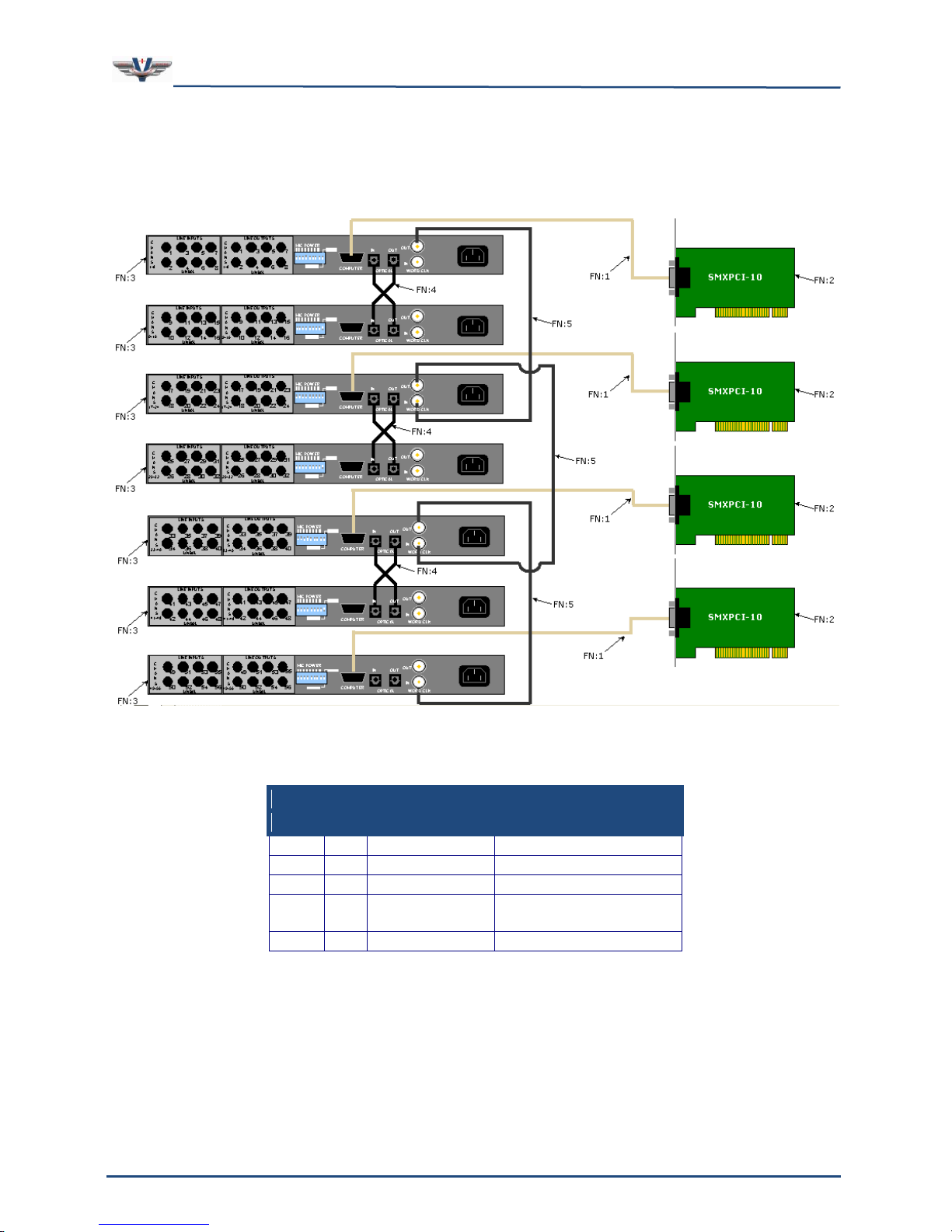
SMx Sync Cable
5.8 48 Channel System
Figure 22 depicts an 48 channel SMx system connection diagram. Table 14 provides the list
of parts for this configuration.
Figure 22, 48 Channel SMx System Connection Diagram
Page 39
SMx Audio System User's Manual, V1.41
SimPhonics, Inc.
Page 39 of 77
Page 39 of 77
Copyright © 2014 SimPhonics, Incorporated, All Rights Reserved
Table 15, 56 Channel SMx System Parts List
Qty
FN
Part No.
Description
4 1 SM4038-xx
SMx Serial Cable
4 2 SMXPCI-10
SMx PCI Card
7 3 SMXB0B-10
SMx Breakout Box
6 4 SM4F01-xx
SMx Plastic Fiber
Optic Cable
3 5 SM4039-xx
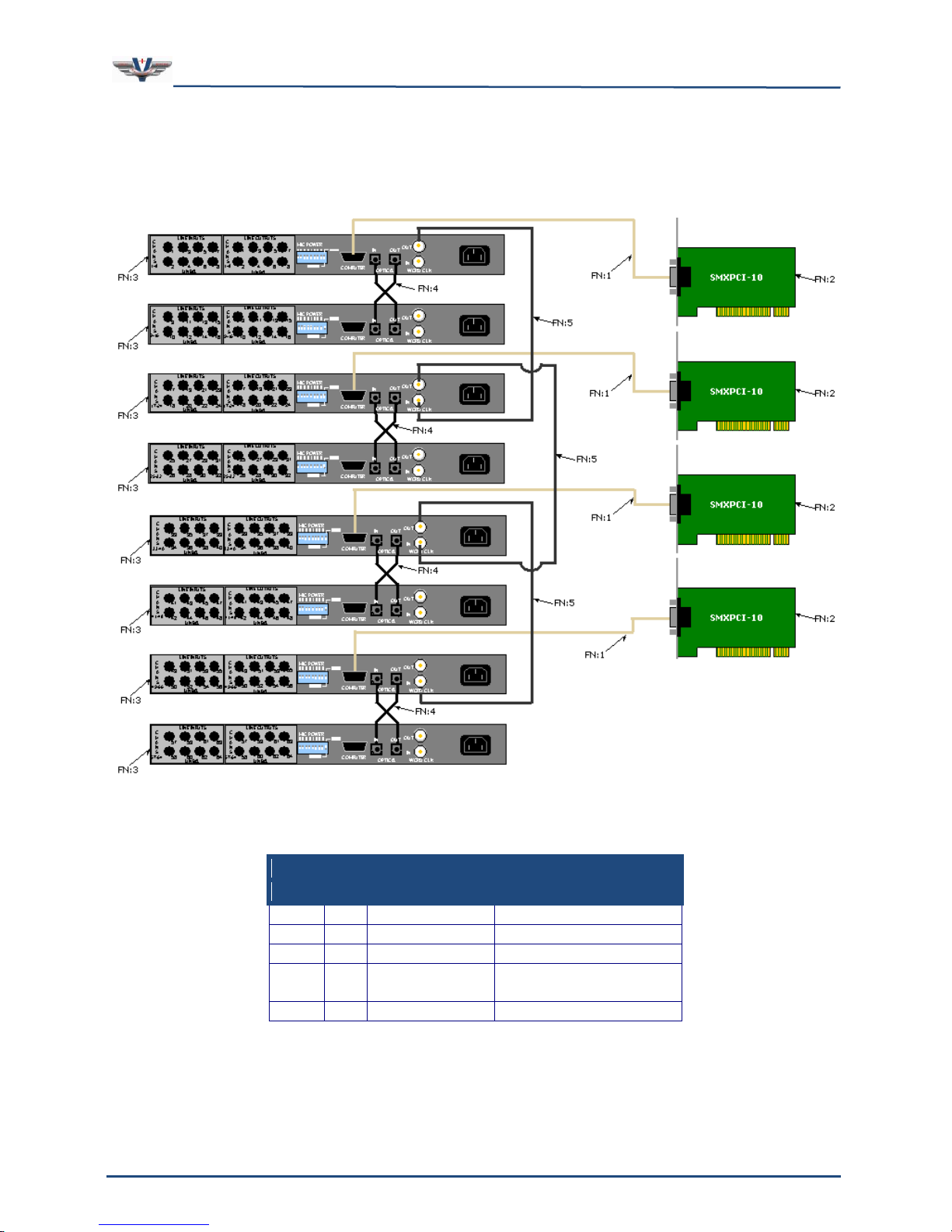
SMx Sync Cable
5.9 56 Channel System
Figure 23 depicts an 56 channel SMx system connection diagram. Table 15 provides the list
of parts for this configuration.
Figure 23, 56 Channel SMx System Connection Diagram
Page 40
SMx Audio System User's Manual, V1.41
SimPhonics, Inc.
Page 40 of 77
Page 40 of 77
Copyright © 2014 SimPhonics, Incorporated, All Rights Reserved
Table 16. 64 Channel SMx System Parts List
Qty
FN
Part No.
Description
4 1 SM4038-xx
SMx Serial Cable
4 2 SMXPCI-10
SMx PCI Card
8 3 SMXB0B-10
SMx Breakout Box
8 4 SM4F01-xx
SMx Plastic Fiber
Optic Cable
3 5 SM4039-xx
SMx Sync Cable
5.10 64 Channel System
Figure 24 depicts an 64 channel SMx system connection diagram. Table 16 provides the list
of parts for this configuration.
Figure 24, 64 Channel SMx System Connection Diagram
Page 41

SMx Audio System User's Manual, V1.41
SimPhonics, Inc.
Page 41 of 77
Page 41 of 77
Copyright © 2014 SimPhonics, Incorporated, All Rights Reserved
6 Software Installation
The following sections describe the SMx software and how to install it on an SMx system.
6.1 Minimum Software Requirements
Most SMx systems are ordered from the factory with software pre-installed. This section is
for those customers installing the software. From June 2013, SimPhonics moved the SMx
from Windows XP to Windows 7, 32-bit only. All future releases of the SMx Audio System
will be on Windows 7 or later releases.
Windows 7 32-bit Professional with Service Pack 1 or greater
V+ version 9.0.503.0 or greater
SMx Audio System Software Build 503 or later
Additional software may be installed for specific configurations. For a list of V+ I/O devices
that may be available, see www.simphonics.com.
6.2 Installing V+
Perform the following steps to install V+ Run-time System:
1. Insert the V+ Run-time System disk into the drive.
2. The installation program will begin automatically.
(Note: If the installation does not begin automatically, select Start » Run and enter
d:\setup. Click OK.)
3. Click Next.
4. Select “I accept the terms in the license agreement”.
5. Click Next.
6. Click Next.
7. Click Install.
8. Click Finish.
9. Remove the disk from the drive when installation is complete.
Page 42

SMx Audio System User's Manual, V1.41
SimPhonics, Inc.
Page 42 of 77
Page 42 of 77
Copyright © 2014 SimPhonics, Incorporated, All Rights Reserved
6.3 Installing the SMx Audio System Software
Perform the following steps to install SMx Audio System Software:
1. Insert the SMX Audio System Software disk into the drive.
2. The installation program will begin automatically.
(Note: If the installation does not begin automatically, select Start » Run and enter
d:\setup. Click OK.)
3. Click Finish when installation is complete.
4. Right-click the My Computer icon on the desktop.
5. Click Properties.
6. Click the Hardware tab.
7. Click Device Manager.
8. Right-click the first Multimedia Controller listed under Other Devices.
9. Click Uninstall.
10. Click OK.
11. Repeat this step for all remaining Multimedia Controller devices.
(Be careful not to uninstall any other type of devices).
12. Click Action.
13. Select Scan for hardware changes.
14. Click Next.
15. Follow the default instructions of the installation dialog boxes.
16. After installation is complete, close all open windows.
17. Remove the disk from the drive.
Page 43

SMx Audio System User's Manual, V1.41
SimPhonics, Inc.
Page 43 of 77
Page 43 of 77
Copyright © 2014 SimPhonics, Incorporated, All Rights Reserved
6.4 Updating the SMx Audio System Software
Perform the following steps for a installing new version of SMx Driver for V+ onto a
computer which already has the SMx Driver installed:
1. Note the Number of Virtual Channels and the Super Mixer Sample Rate settings for
your application before you install the new SMx driver. These values will be used
after installing the new SMx driver.
2. Remove the V+ application by selecting Start » Settings » Control Panel
followed by double-clicking Add or Remove Programs.
3. Select SMx Audio System and click Remove.
4. Click Yes to remove the SMx driver from your computer.
5. Click Finish.
6. If your new version of the SMx driver is on CD, insert it into your CD drive. The
installation should automatically start. If it doesn’t, click Start » Run and type
D:\setup.exe followed by clicking OK.
7. If your new version of SMx Driver is simply the setup.exe file, double-click the
file.
8. Click Finish.
9. Ensure that your breakout boxes are powered on.
10. Reboot the computer.
11. After the computer has finished rebooting, Start the V+ Run Time System and click
Configure.
12. Double-click the SMx Audio System driver to enable it
13. Click the Configure button.
14. Set the Number of Virtual Channels and Super Mixer Sample Rate to the settings
you noted in Step 1 above.
15. Click OK.
16. Click Yes.
17. Click OK.
18. Click OK.
19. Close the V+ Run Time System window and reboot the computer.
Page 44
SMx Audio System User's Manual, V1.41
SimPhonics, Inc.
Page 44 of 77
Page 44 of 77
Copyright © 2014 SimPhonics, Incorporated, All Rights Reserved
6.5 Configuring SMx within V+
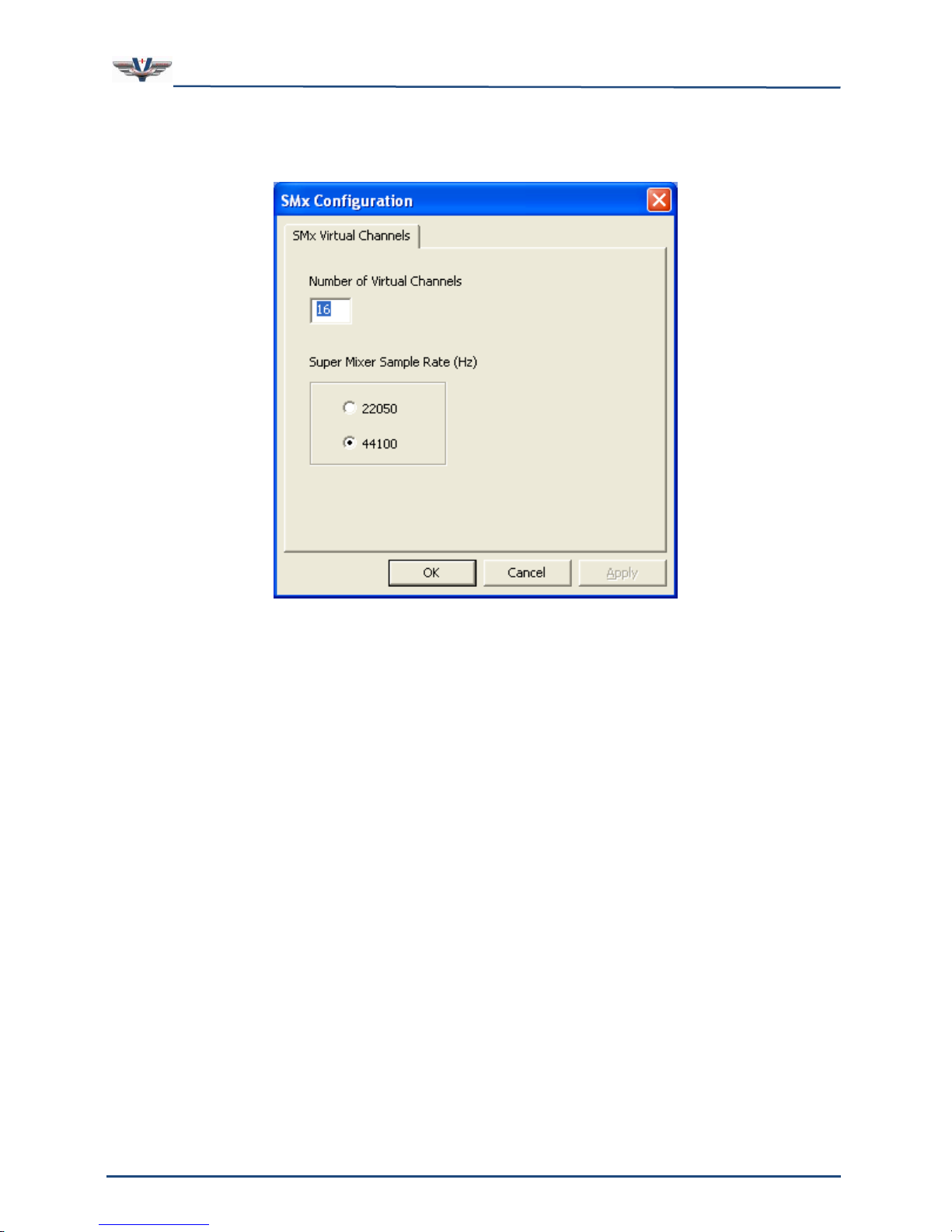
There are two user configurable items in the SMx software. The first is the number of virtual
channels. Virtual channels are the WI and WO channels that are connected to the Super
Mixer. The default number of virtual channels is set to 16 for both WO and WI channels
regardless of the number of physical channels in the SMx system. The second configurable
item is the Super Mixer Sample Rate. Two choices are available: 22050 and 44100. It is
advisable to keep the 44 KHz sampling rate as this provides better quality sound when
playing wave files. However, if run-time performance is below acceptable limits for your
program, try setting the sample rate to 22 KHz.
Note: If you have a voice only application, such as for communications and/or networked
radios, setting the sample rate to 22 KHz has little or no effect on the quality due to the
limited frequency range of voice.
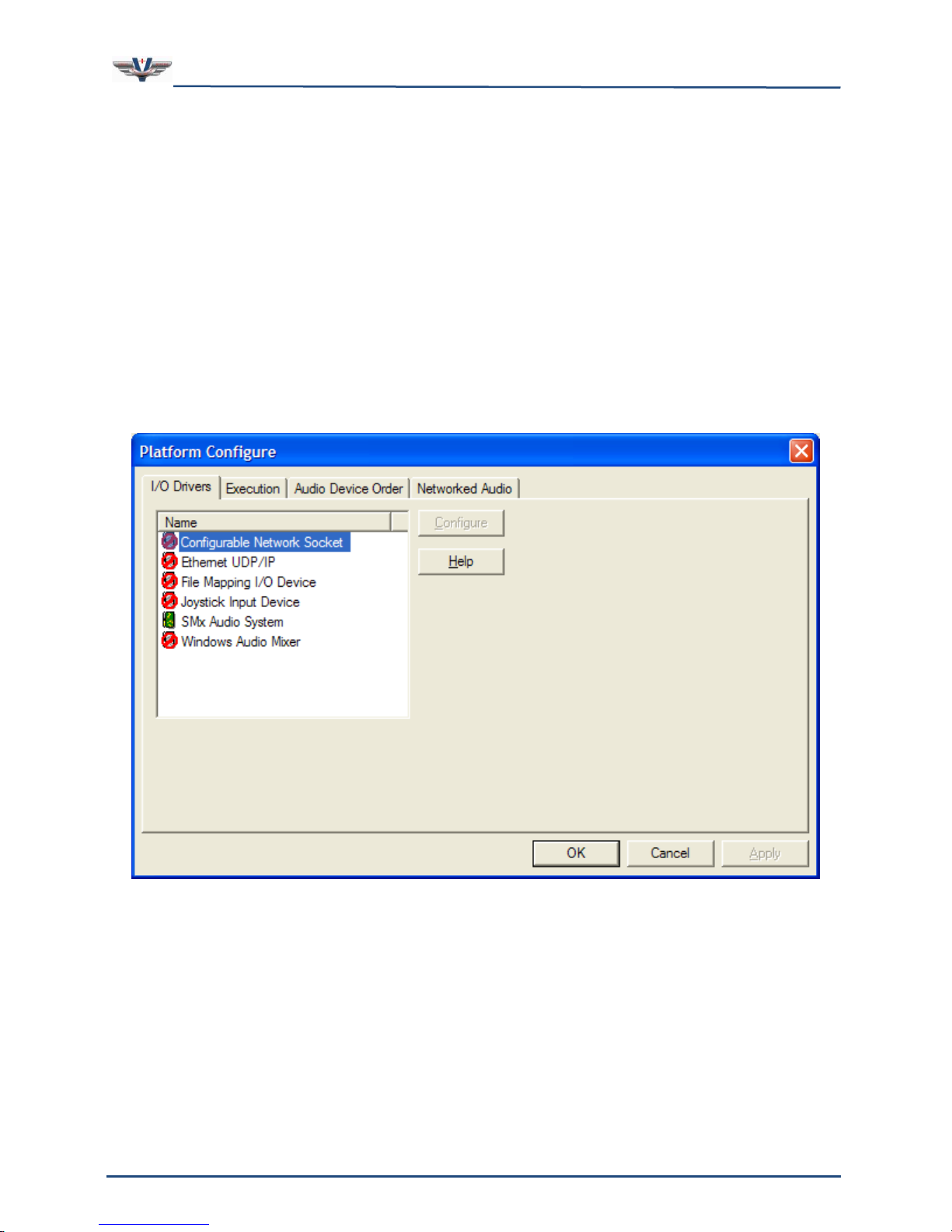
While in the V+ Run Time System window, select the Configure menu and the Platform
Configure window shown in Figure 25 will appear.
Figure 25, V+ Platform Configure Window
Page 45
SMx Audio System User's Manual, V1.41
SimPhonics, Inc.
Page 45 of 77
Page 45 of 77
Copyright © 2014 SimPhonics, Incorporated, All Rights Reserved
Double-click the SMx Audio System I/O driver (which will turn the icon to the left of it
green), followed by clicking the Configure button. The SMx Configuration window shown in
Figure 26 will appear.
Figure 26, SMx Configuration Window
Enter the desired number of virtual channels in the dialog box. This must be an even
number since there are two channels per device. Valid numbers are even integers from 2 to
64. Once the number is entered, you will be prompted to confirm the change. Click Yes. You
will then be notified that these channels will not appear until the machine is rebooted.
Note: This number of channels and sample rate will remain the same until the changed
again via this interface. These values are stored in the system registry. If either of these
parameters is modified, the system must be rebooted for the change(s) to take effect.
Page 46
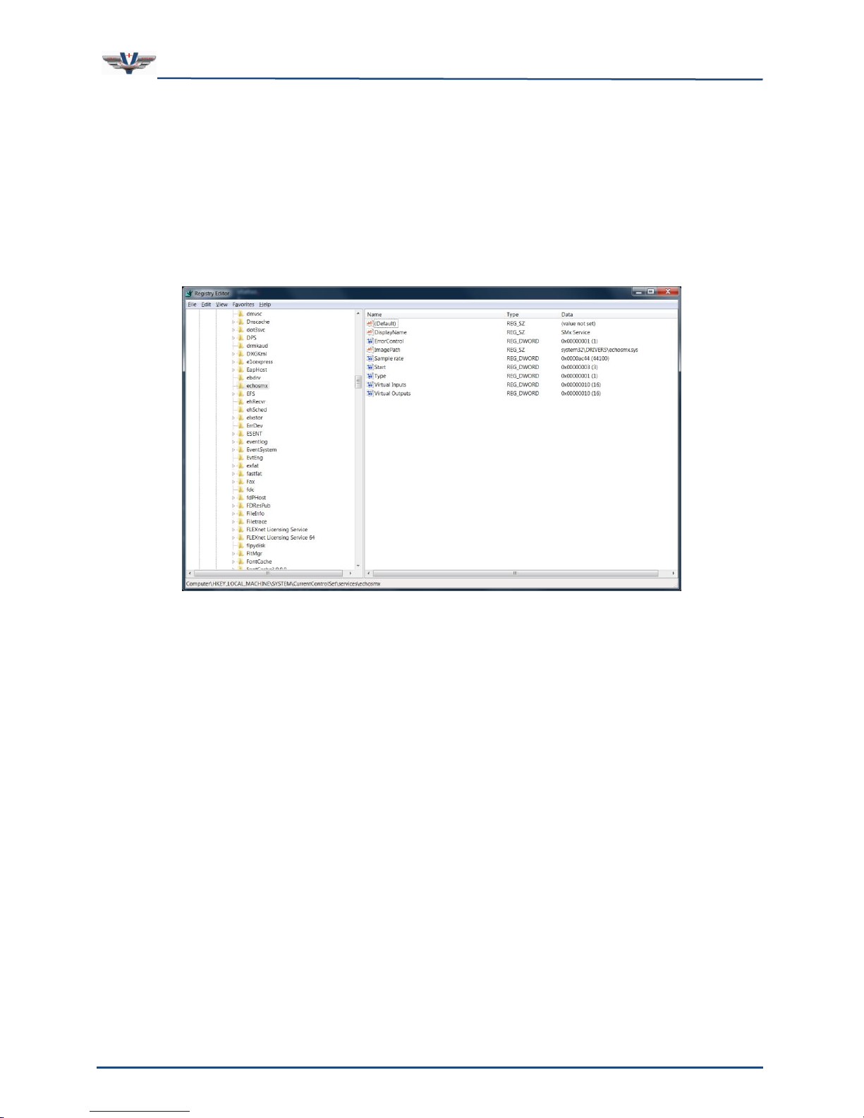
SMx Audio System User's Manual, V1.41
SimPhonics, Inc.
Page 46 of 77
Page 46 of 77
Copyright © 2014 SimPhonics, Incorporated, All Rights Reserved
7 Registry Settings
A variety of run-time information can be setup for the SMx system in the system registry.
The base registry location is at:
/HKEY_LOCAL_MACHINE/SYSTEM/CurrentControlSet/services/echosmx
Do not change the other registry data.
Page 47
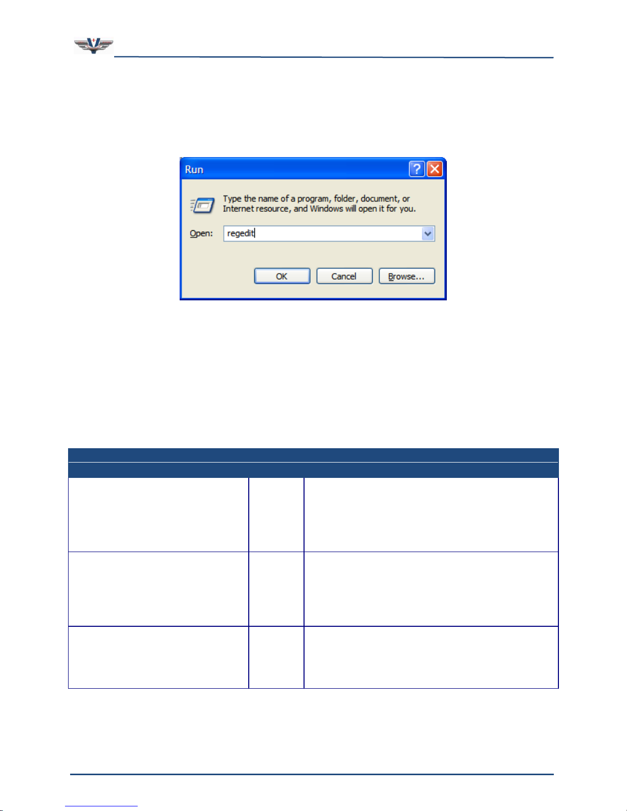
SMx Audio System User's Manual, V1.41
SimPhonics, Inc.
Page 47 of 77
Page 47 of 77
Copyright © 2014 SimPhonics, Incorporated, All Rights Reserved
Table 17, MISC Registry Key
Entry
Type
Description
Virtual Inputs
DWORD
This value is the number of virtual channels
for Inputs that will be shown in the user
interface.
This value is installed and set to 16 (0x10) by
default.
Virtual Outputs
DWORD
This value is the number of virtual channels
for Outputs that will be shown in the user
interface.
This value is installed and set to 16 (0x10) by
default.
Sample rate
DWORD
This is the sample rate use by the SMx and
displayed in the user interface.
This value is installed and set to 0x0000ac44
(44100) by default.
Changing Registry Settings
When editing the registry use extreme caution since you can easily render your computer
useless by changing the wrong data. To access the registry, click Start » Run which will
open the Run dialog box as shown in Figure 27. Enter the command regedit and click OK.
This will start the Registry Editor.
Figure 27, Run Dialog Box
When editing registry values navigate to the base registry key shown earlier. Be sure to
enter the new key name before adding a new value (entry) if it does not already exist. Also
make sure to use the correct data type. Note that the key and entry name must match
exactly. The following sections identify and describe the VComm keys and their associated
entries (values).
Key name: /HKEY_LOCAL_MACHINE/SYSTEM/CurrentControlSet/echosmx
These values have miscellaneous purposes as explained in Table 17.
Page 48

SMx Audio System User's Manual, V1.41
SimPhonics, Inc.
Page 48 of 77
Page 48 of 77
Copyright © 2014 SimPhonics, Incorporated, All Rights Reserved
8 Using V+ with SMx
SMx is completely user programmable right down to multiplies and OR gates without having
to write a single line of text-based code! You are not constrained with a fixed model or
factory feature, and you have complete visibility and control into the operation of the
system. The user can connect individual data from one I/O device to another with a click of
a mouse.
One of the advantages of using V+ is the self-documenting paradigm that is inherent within
a visual programming system. The design executes directly without the need for compiling.
The bottom line is – flexibility and freedom; freedom to create new applications without the
worry of model charges, royalties, and ridiculous charges for simple changes. Remember, all
of SimPhonics’ software is available free of charge for evaluation at www.simphonics.com.
8.1 Application Examples
The SMx system is shipped with sample V+ designs on the CPU hard drive. These are copies
of those available at www.simphonics.com/library/VPLusSamples. New design examples will
be added as SimPhonics evolves newer applications and tutorials.
All example files are located on the SMx hard drive in the following folder:
C:\Program Files\VPLus\VPLus Samples\…
Sample wave-files are located on the SMx hard drive in the following folder:
C:\Program Files\VPLus\VPLus Samples\Wavefiles
Page 49
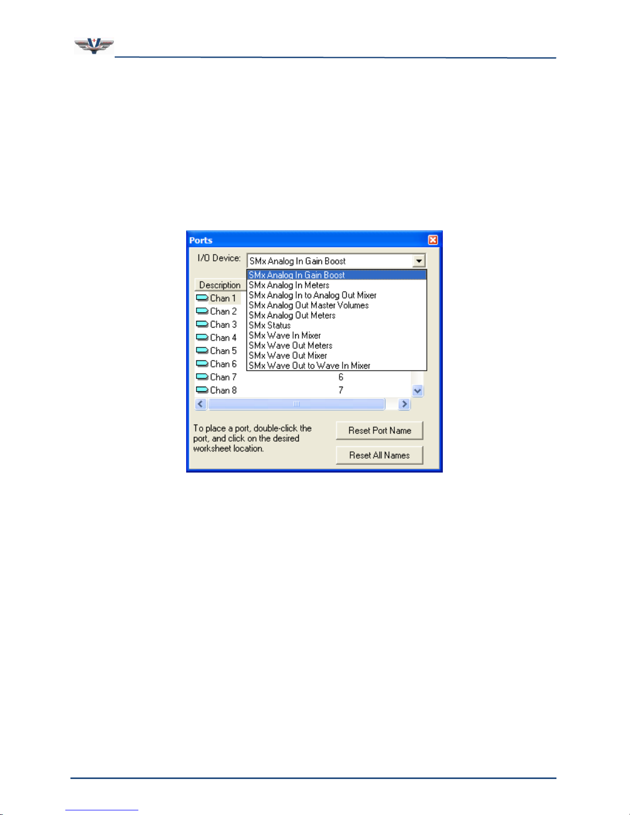
SMx Audio System User's Manual, V1.41
SimPhonics, Inc.
Page 49 of 77
Page 49 of 77
Copyright © 2014 SimPhonics, Incorporated, All Rights Reserved
8.2 The SMx Super Mixer
8.3 SMx I/O Devices for the SMx Audio System
The SMx I/O devices are installed when the “SMx Audio System Software” CD is installed.
Once this software is installed, the driver can be activated from the run-time system. There
are 10 I/O devices available in V+ for controlling the SMx Super Mixer. These devices are
shown in Figure 28, and are described in greater detail below. Each device is used to control
a component of the Super Mixer and is composed of a list of ports. Each port is assigned a
specific function within the I/O device.
Figure 28, SMx I/O Devices
The SMx defaults to an off condition, so that when V+ is not running and a Super Mixer
component is not enabled, the SMx audio system will not pass any audio in any direction.
Also, when V+ is started or stopped, all of the ports for each Super Mixer I/O device are set
to zero. This ensures that any previous settings are reset to zero.
Page 50
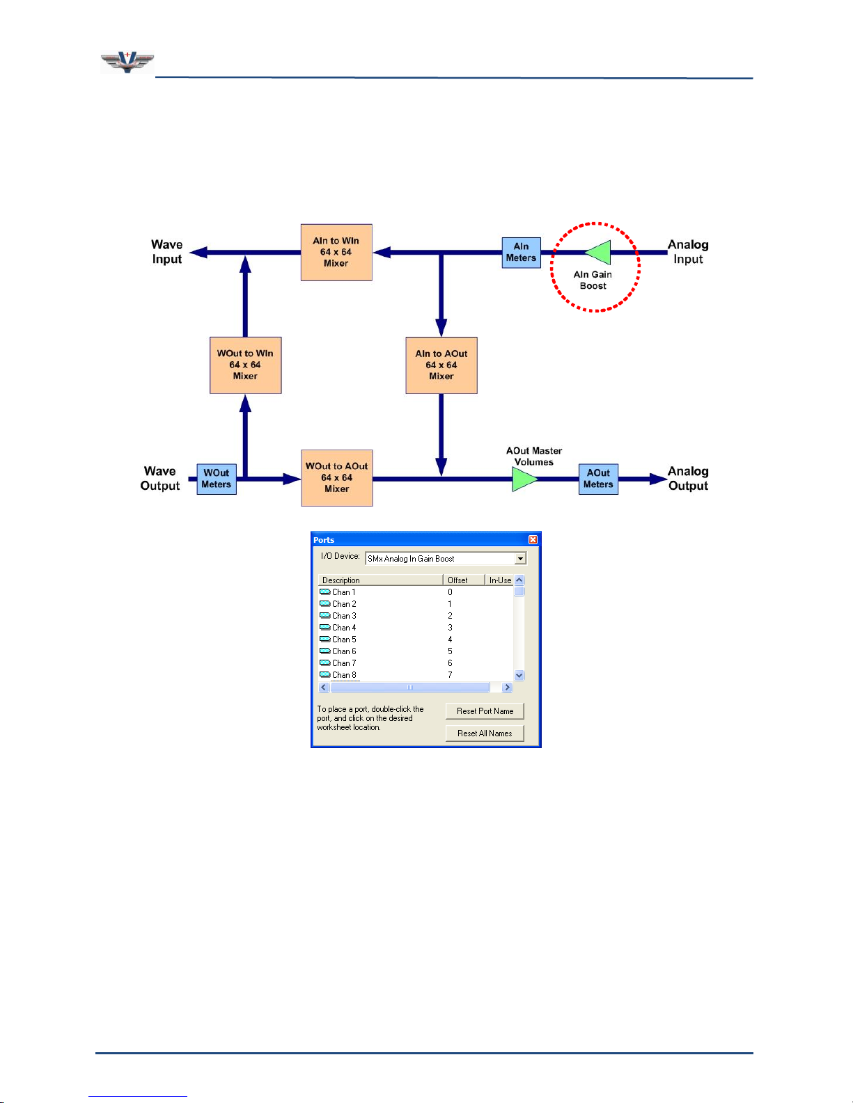
SMx Audio System User's Manual, V1.41
SimPhonics, Inc.
Page 50 of 77
Page 50 of 77
Copyright © 2014 SimPhonics, Incorporated, All Rights Reserved
8.3.1 SMx Analog In Gain Boost Device
This device is used to boost the gain of the input signal (see Figure 29). Each analog input
has a gain boost port in V+ that can be used to boost the gain by as much as +60 dB in
increments of 6 dB. A value of 0.0 represents unity gain. If the port for a given channel is
not used on a worksheet, the gain boost in set to 0 for that channel.
Figure 29, SMx Analog in Gain Boost Device
For example, assume that the input signal is a sine wave of 2.5Vrms. Using a gain boost of
+6 will increase the level of the signal to +5Vrms before the signal is applied to the system.
Ports for this device are named “Chan 1” through “Chan 64”. The SMx has an exceptional
dynamic range due to its 24 bit resolution. However, the dynamic range of the input signal
is reduced when boosting gain. A signal is boosted digitally so that each 6 dB increase in
gain results in a loss of 1 bit of range. Therefore, a +60 dB increase results in a loss of 10
bits. The analog-to-digital conversion is 24 bits in length, so a 60 dB boost still results in a
14-bit signal, which is only 2 bits less than CD quality. If you want at least CD quality of 16
bits, keep the boost less than or equal to 48 dB.
Page 51

SMx Audio System User's Manual, V1.41
SimPhonics, Inc.
Page 51 of 77
Page 51 of 77
Copyright © 2014 SimPhonics, Incorporated, All Rights Reserved
8.3.2 SMx Analog In Meters Device
This device is used to monitor the input signal level of each channel (see Figure 30). There
are 64 ports in this device, each of which is associated with one of the 64 input channels.
The monitor is placed after the gain boost. The monitor port value represents the true RMS
voltage level of the input signal multiplied times 2000, averaged over a ten-millisecond
interval. Therefore a true sine wave input of 1 volt at 1,000 Hertz will produce a reading of
2000+/- .1 %.
Figure 30, SMx Analog in Meters Device
Ports for this device are named “Analog In 1 VU Meter” through “Analog In 64 VU Meter”.
This device is typically used to construct VOX designs. Monitoring the meter value and
determining when a valid signal is present on the input accomplishes this. See the
application section for more information.
Page 52
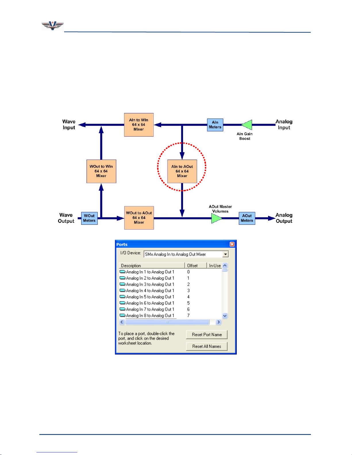
SMx Audio System User's Manual, V1.41
SimPhonics, Inc.
Page 52 of 77
Page 52 of 77
Copyright © 2014 SimPhonics, Incorporated, All Rights Reserved
8.3.3 SMx Analog In to Analog Out Mixer Device
This device can mix any analog input to any analog output in any combination (see Figure
31). The mixer is a 64 input X 64 output mixer consisting of 4,096 V+ ports. Most
applications only use a small portion of these ports. A maximum value of 1.0 represents
unity gain and a minimum value 0.0 represents off. Unused ports are automatically set to a
gain value to 0. Each input signal that is mixed to an output is summed together at that
output. Therefore, input signals accumulate in amplitude. Gain controls are linear 16 bit
values which represent voltage attenuation.
Figure 31, SMx Analog In to Analog Out Mixer Device
Ports are named “Analog In 1 to Analog Out 1” through “Analog In 64 to Analog Out 64”. For
example, to mix input channel 1 to output channel 5, set port "Analog In 1 to Analog Out 5”
to some value greater than 0.0 and less than or equal to 1.0.
Page 53
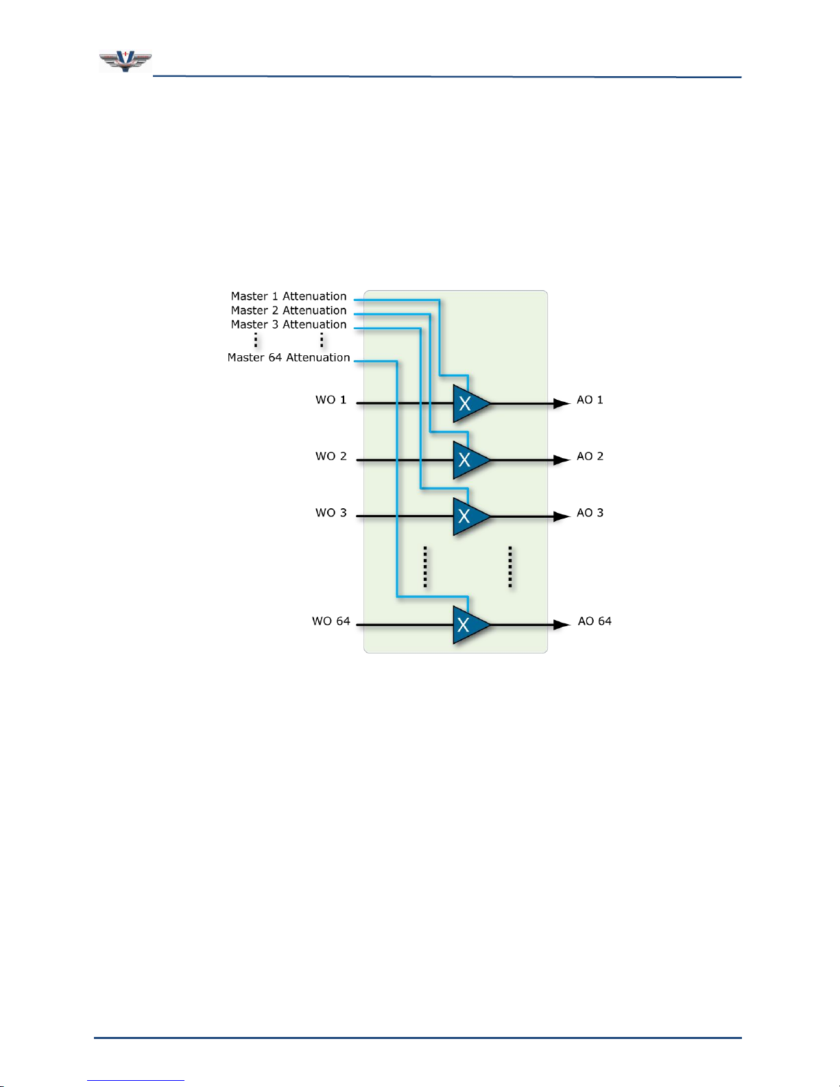
SMx Audio System User's Manual, V1.41
SimPhonics, Inc.
Page 53 of 77
Page 53 of 77
Copyright © 2014 SimPhonics, Incorporated, All Rights Reserved
8.3.4 SMx Analog Out Master Volume Device
This device is used to set the attenuation of the output levels of each output channel (see
Figure 33). Therefore, there are 64 ports in this device, one for each output channel. A
maximum value of 1.0 represents unity gain and a minimum value 0.0 represents off.
Unused ports are automatically set to 0. Port controls are linear 16 bit values which
represent voltage attenuation.
Figure 32, SMx 64 Master Attenuators (Volumes)
Page 54
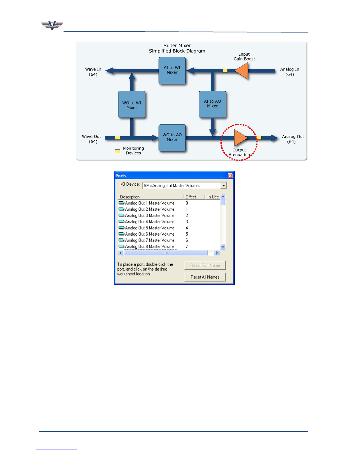
SMx Audio System User's Manual, V1.41
SimPhonics, Inc.
Page 54 of 77
Page 54 of 77
Copyright © 2014 SimPhonics, Incorporated, All Rights Reserved
Figure 33, SMx Analog Out Master Volume Device
Ports are named “Analog Out 1 Master Volume” through “Analog Out 64 Master Volume”.
Unless these ports are set to some value greater than 0.0, no signal will be present on the
output, since this attenuation is just before the output is applied to the output connector.
Page 55
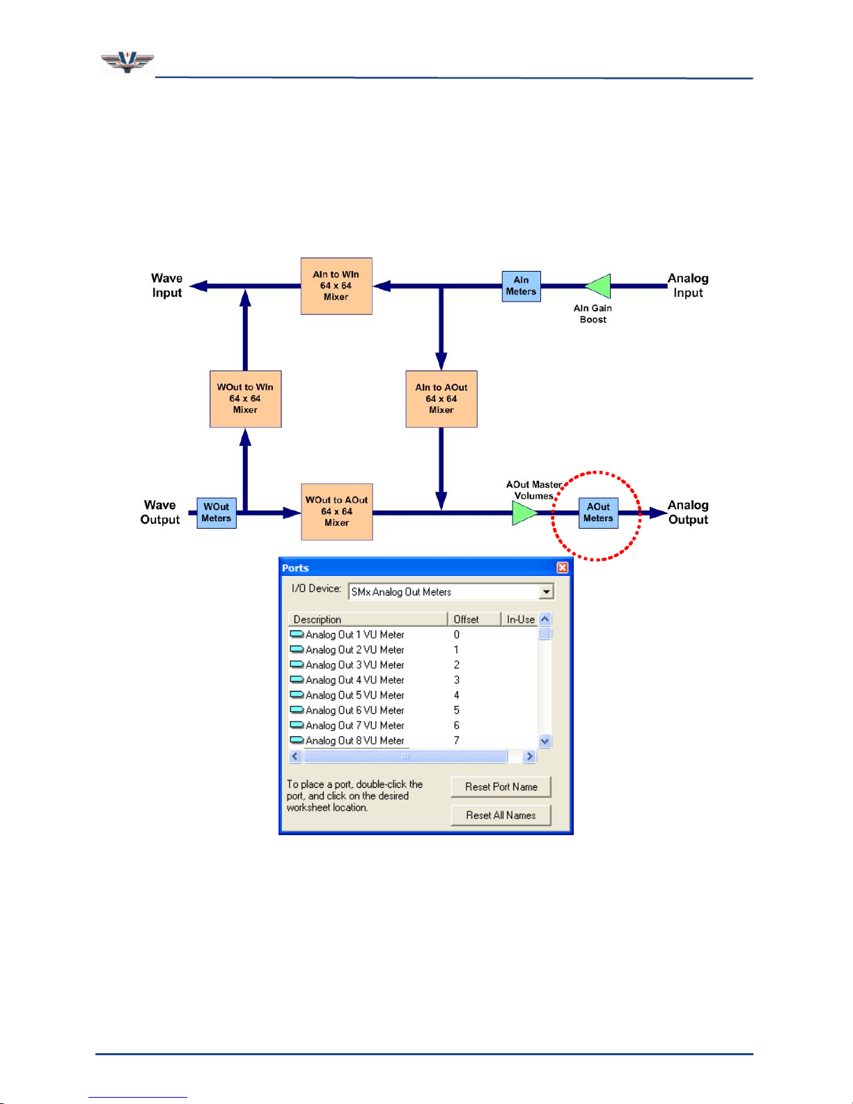
SMx Audio System User's Manual, V1.41
SimPhonics, Inc.
Page 55 of 77
Page 55 of 77
Copyright © 2014 SimPhonics, Incorporated, All Rights Reserved
8.3.5 SMx Analog Out Meters Device
This device is used to monitor the output signal level of each channel (see Figure 34). There
are 64 ports in this device, each of which is associated with one of the 64 output channels.
The monitor is placed after the master volumes so that the effects of the master volume can
be observed. The monitor port value represents the peak voltage level of the output signal,
averaged over a ten-millisecond interval. The scaling on this device is such that the value
represents the output RMS voltage on the output channel.
Figure 34, SMx Analog Out Meters Device
Ports for this device are named “Analog Out 1 VU Meter” through “Analog Out 64 VU Meter”.
Monitoring the meter value and determining when a valid signal is present on the output
can be used to turn on an LED indicating activity on an output.
Page 56
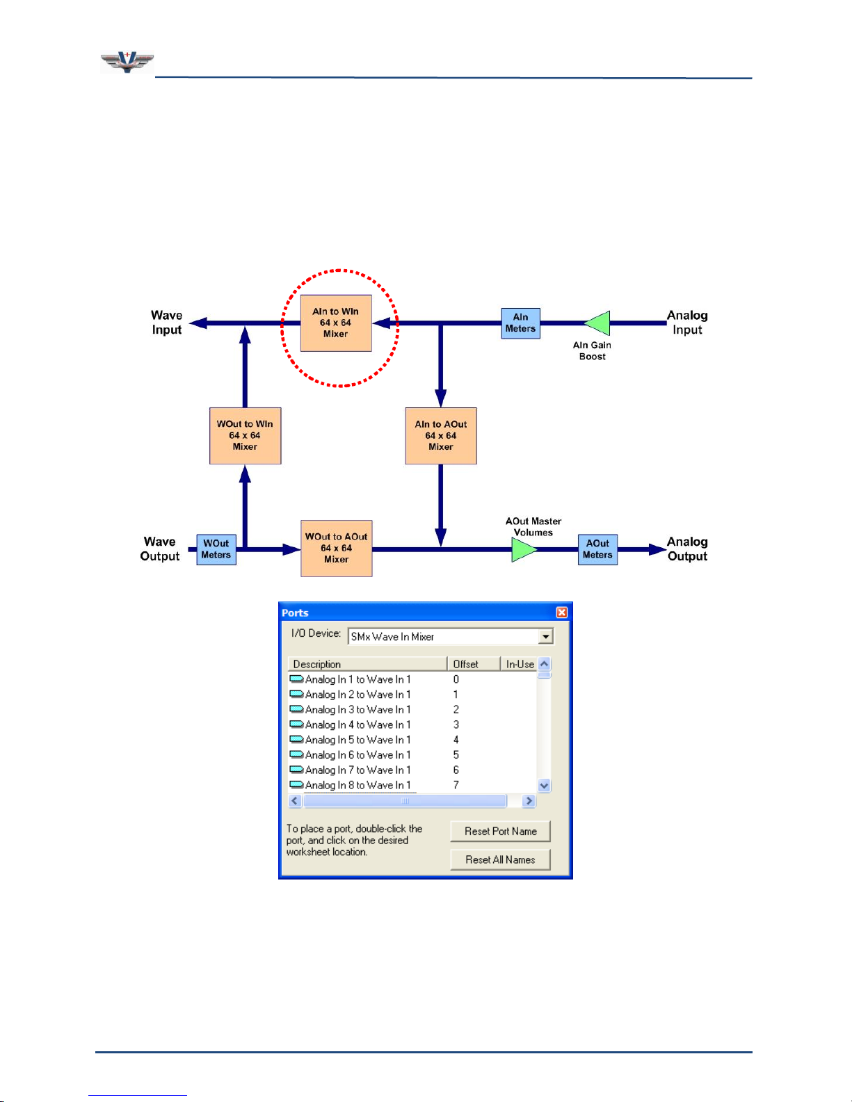
SMx Audio System User's Manual, V1.41
SimPhonics, Inc.
Page 56 of 77
Page 56 of 77
Copyright © 2014 SimPhonics, Incorporated, All Rights Reserved
8.3.6 SMx Wave In Mixer Device
This device controls the attenuation of signals flowing from the SMx analog input to the PC
Wave Input (see Figure 35). There are up to 64 channels of input from the PC system that
can be applied to the input of the mixer. The mixer can mix any input SMx channel to any
one of the outputs of this mixer, which is then applied to the Wave In system of the PC. A
maximum value of 1.0 represents unity gain and a minimum value 0.0 represents off.
Unused ports are automatically set to 0. Port controls are linear 16 bit values which
represent voltage attenuation.
Figure 35, SMx Wave In Mixer Device
Ports are named “Analog In 1 to Wave In 1” through “Analog In 64 to Wave In 64”. Before
any AI signal can be sent to a WI stream, such as for recording or networked audio (radios),
the respective AI to WO port must be utilized.
Page 57
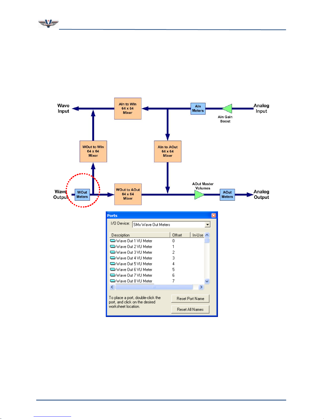
SMx Audio System User's Manual, V1.41
SimPhonics, Inc.
Page 57 of 77
Page 57 of 77
Copyright © 2014 SimPhonics, Incorporated, All Rights Reserved
8.3.7 SMx Wave Out Meters Device
This device is used to monitor the output signal level of each Wave Out channel (see Figure
36). There are 64 ports in this device, each of which is associated with one of the 64 Wave
Out channels. The monitor is placed immediately following the Wave Ouputs of the Windwos
Audio Mixer. The monitor port value represents the peak voltage level of the output signal,
averaged over a ten-millisecond interval. The scaling on this device is such that the value
represents the output RMS voltage on the output channel.
Figure 36, SMx Wave Out Meters Device
Ports for this device are named “Wave Out 1 VU Meter” through “Wave Out 64 VU Meter”.
Monitoring the meter value and determining when a valid signal is present on the output
can be used to turn on an LED indicating activity on a Wave Output.
Page 58
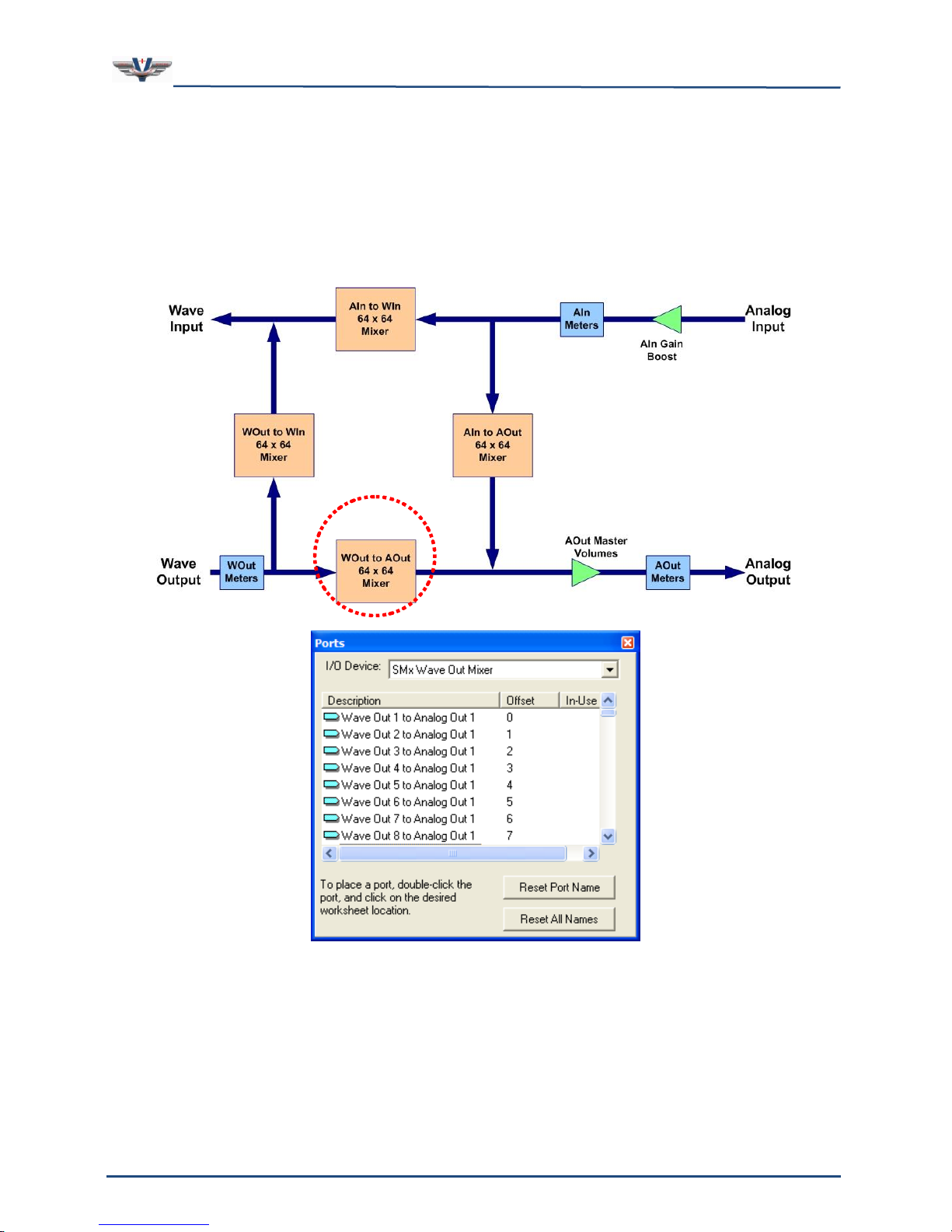
SMx Audio System User's Manual, V1.41
SimPhonics, Inc.
Page 58 of 77
Page 58 of 77
Copyright © 2014 SimPhonics, Incorporated, All Rights Reserved
8.3.8 SMx Wave out Mixer Device
This device controls the attenuation of signals flowing from the PC Wave output to the SMx
system (see Figure 37). There are up to 64 channels of wave output available for allocation
within the SMx. The mixer can mix any of these wave output channels to any one of the
analog outputs of this mixer. A maximum value of 1.0 represents unity gain and a minimum
value 0.0 represents off. Unused ports are automatically set to 0. Port controls are linear 16
bit values which represent voltage attenuation.
Figure 37, SMx Wave Out Mixer Device
Ports are named “Wave Out 1 to Analog Out 1” through “Wave Out 64 to Analog Out 64”.
Before any WO signal can be sent to an AO, at least two ports must be utilized. One for the
AO’s master gain, and one for the specific WO to AO channel.
Page 59
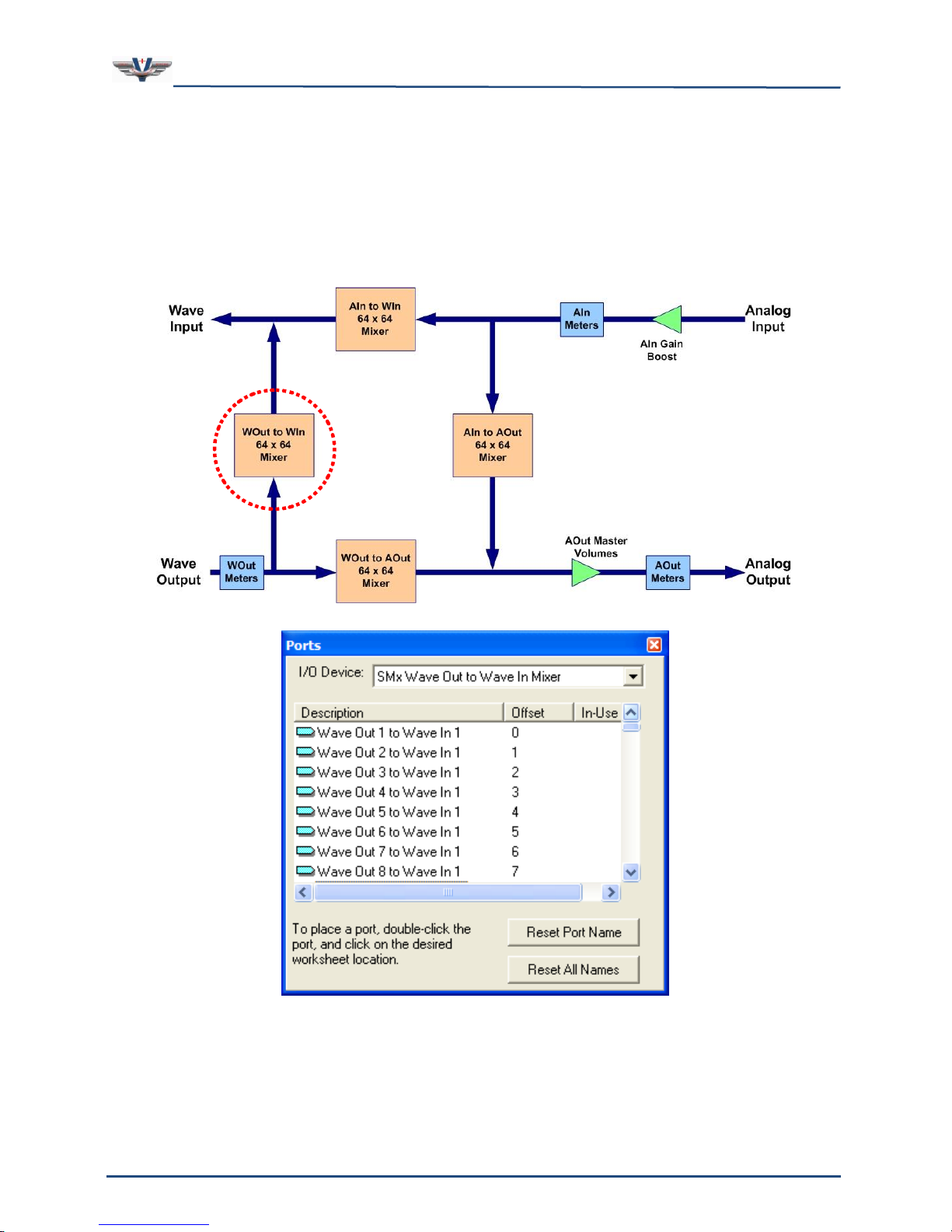
SMx Audio System User's Manual, V1.41
SimPhonics, Inc.
Page 59 of 77
Page 59 of 77
Copyright © 2014 SimPhonics, Incorporated, All Rights Reserved
8.3.9 SMx Wave Out to Wave in Mixer Device
This device controls the attenuation of signals flowing from the PC Wave output to the SMx
system (see Figure 38). There are up to 64 channels of wave output available for allocation
within the SMx. The mixer can mix any of these wave output channels to any one of the
analog outputs of this mixer. A maximum value of 1.0 represents unity gain and a minimum
value 0.0 represents off. Unused ports are automatically set to 0. Port controls are linear 16
bit values which represent voltage attenuation.
Figure 38, SMx Wave Out to Wave In Mixer Device
Ports are named “Wave Out 1 to Wave In 1” through “Wave Out 64 to Wave In 64”. This
mixer can be used to send the audio stream of a wave file player to a VComm radio, which
will result in this stream being sent over the network.
Page 60
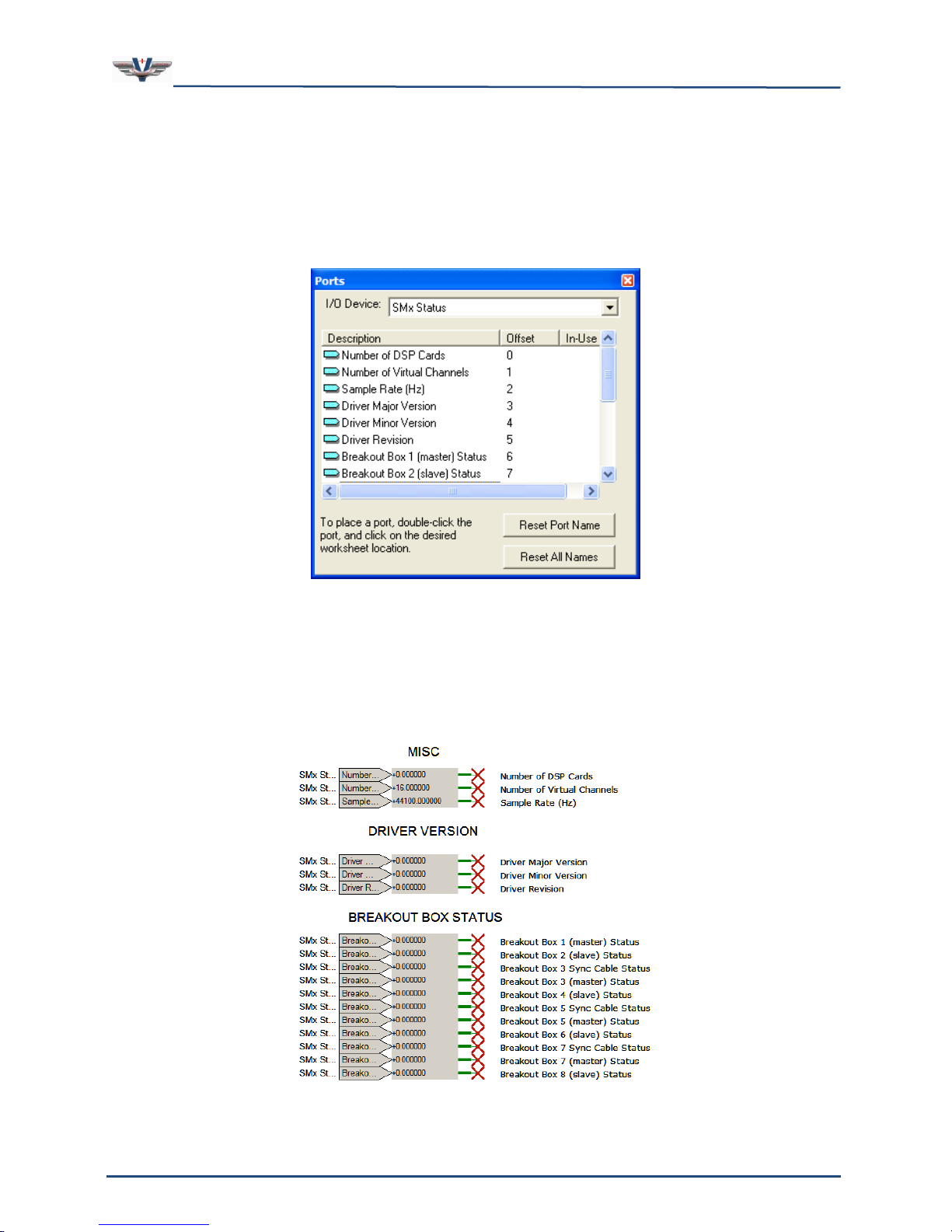
SMx Audio System User's Manual, V1.41
SimPhonics, Inc.
Page 60 of 77
Page 60 of 77
Copyright © 2014 SimPhonics, Incorporated, All Rights Reserved
8.3.10 SMx Status Device
The SMx Audio System I/O Device for V+ device version 4.3.0.124 (Build 124) and later
versions include a new input device, “SMx Status” device (see Figure 39). This new device
has a number of input ports that report real-time properties of the system. This information
is useful for diagnostics that can be reported back to a host computer, to a user of the
system via a GUI, or whatever the V+ designer chooses.
Figure 39, SMx Status Device
8.3.11 Simulated Hardware Mode
If the SMx hardware is not present in the computer when the status device is run, the status
ports will report back the values shown in Figure 40, SMx Simulated Hardware Mode Status
Ports. Not all ports produce results that are expected in this mode.
Figure 40, SMx Simulated Hardware Mode Status Ports
Page 61

SMx Audio System User's Manual, V1.41
SimPhonics, Inc.
Page 61 of 77
Page 61 of 77
Copyright © 2014 SimPhonics, Incorporated, All Rights Reserved
If an error is detected during pre-execute of the “SMx Audio System” I/O Device then V+
will not start. Pre-execution errors are displayed in the V+ Run Time message window.
Errors encountered during execution are reported via ports and in the V+ Run Time message
window. The SMx Status Device contains the following input ports shown in the order that
they appear in the port list:
1. Number of DSP Cards – The number of DSP cards is reported on this input port.
Valid values are 0, 1, 2, 3, and 4. Zero indicates that either breakout boxes are
turned off, or that the system is operating in Software Emulation Mode.
2. Number of Virtual Channels – This input port will reflect the number of virtual
channels currently configured. The user can change this value in the configuration
dialog of the V+ Run Time System. The number of channels is the same for input and
output. Valid values are even numbers from 2 through 64. If this value is ever zero,
this indicates that the driver was not installed properly since the installation software
for the SMx Audio System sets this value in the registry to a default of 16. The user
may change this value from that point on.
3. Sample Rate – This input port is the sample rate of the SMx system in samples per
second. The default is 44,100.
4. Driver Major Version – This is the major version number of the hardware driver
(echosmx.sys). The format of the version numbers of this driver are a.b.c, where a is
the major version number, b is the minor version, and c is the revision number.
5. Driver Minor Version – This is the minor version number of the hardware driver
(echosmx.sys).
6. Driver Revision – This is the revision number of the hardware driver (echosmx.sys).
7. Breakout Box 1 (master) Status – This port indicates the status of the first
breakout box (which is a master). A status of 1 indicates that the breakout box is
powered on and connected to the first DSP card. A status of 0 indicates that the
breakout box is either powered off, its serial cable is disconnected, the breakout box
has failed, or that the first DSP card has failed.
8. Breakout Box 2 (slave) Status – This port indicates the status of the second
breakout box (which is a slave). A status of 1 indicates that the breakout box is
powered on and connected to its master breakout box. A status of 0 indicates that
the breakout box is either powered off, one of its fiber optic cables is disconnected,
the breakout box has failed, or that the breakout box 1 has failed.
9. Breakout Box 3 Sync Cable Status – This port indicates the status of the sync
cable connecting breakout box 1 to breakout box 3. A status of 1 indicates that the
cable is properly connected between the breakout boxes. A status of 0 indicates that
it is not.
10. Breakout Box 3 (master) Status – This port indicates the status of the third
breakout box (which is a master). A status of 1 indicates that the breakout box is
powered on and connected to the second DSP card. A status of 0 indicates that the
breakout box is either powered off, its serial cable is disconnected, the breakout box
has failed, or that the second DSP card has failed.
11. Breakout Box 4 (slave) Status – This port indicates the status of the fourth
breakout box (which is a slave). A status of 1 indicates that the breakout box is
powered on and connected to its master breakout box. A status of 0 indicates that
the breakout box is either powered off, one of its fiber optic cables is disconnected,
the breakout box has failed, or that the breakout box 3 has failed.
12. Breakout Box 5 Sync Cable Status – This port indicates the status of the sync
cable connecting breakout box 3 to breakout box 5. A status of 1 indicates that the
Page 62

SMx Audio System User's Manual, V1.41
SimPhonics, Inc.
Page 62 of 77
Page 62 of 77
Copyright © 2014 SimPhonics, Incorporated, All Rights Reserved
cable is properly connected between the breakout boxes. A status of 0 indicates that
it is not.
13. Breakout Box 5 (master) Status – This port indicates the status of the fifth
breakout box (which is a master). A status of 1 indicates that the breakout box is
powered on and connected to the third DSP card. A status of 0 indicates that the
breakout box is either powered off, its serial cable is disconnected, the breakout box
has failed, or that the third DSP card has failed.
14. Breakout Box 6 (slave) Status – This port indicates the status of the sixth
breakout box (which is a slave). A status of 1 indicates that the breakout box is
powered on and connected to its master breakout box. A status of 0 indicates that
the breakout box is either powered off, one of its fiber optic cables is disconnected,
the breakout box has failed, or that the breakout box 5 has failed.
15. Breakout Box 7 Sync Cable Status – This port indicates the status of the sync
cable connecting breakout box 5 to breakout box 7. A status of 1 indicates that the
cable is properly connected between the breakout boxes. A status of 0 indicates that
it is not.
16. Breakout Box 7 (master) Status – This port indicates the status of the seventh
breakout box (which is a master). A status of 1 indicates that the breakout box is
powered on and connected to the fourth DSP card. A status of 0 indicates that the
breakout box is either powered off, its serial cable is disconnected, the breakout box
has failed, or that the fourth DSP card has failed.
17. Breakout Box 8 (slave) Status – This port indicates the status of the fourth
breakout box (which is a slave). A status of 1 indicates that the breakout box is
powered on and connected to its master breakout box. A status of 0 indicates that
the breakout box is either powered off, one of its fiber optic cables is disconnected,
the breakout box has failed, or that the breakout box 7 has failed.
Page 63

SMx Audio System User's Manual, V1.41
SimPhonics, Inc.
Page 63 of 77
Page 63 of 77
Copyright © 2014 SimPhonics, Incorporated, All Rights Reserved
8.4 “2103 SMx W I/O Select to A I/O” Object
The Super Mixer is so complex and contains so many ports, that a new object was necessary
to simplify V+ worksheet applications where an A I/O pair (Headset/Microphone for
example) had to select a WI and WO pair (Simulated Radio for example) that could be one
of any of the 64 pairs. For example, if an operator using a headset/microphone had a user
interface that could select any one of the 64 WI/WO for a simulated radio, then all of the
ports for the AI 1 to WI 1 through WI 64 would have to be placed on a worksheet along with
the same concept for the Headset as WO 1 through WO 64 to AO 1. This would require all
of the ports in the mixer! A new object had to be developed that could simplify this
condition.
8.4.1 “2103 SMx W I/O Select to A I/O”
Page 64
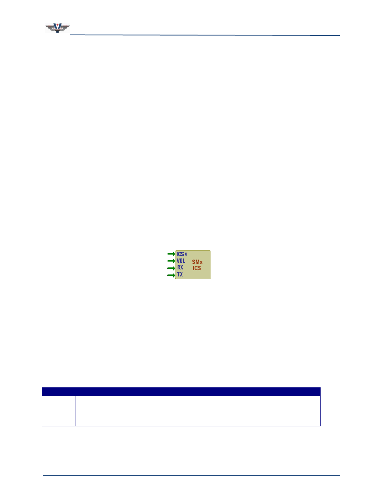
SMx Audio System User's Manual, V1.41
SimPhonics, Inc.
Page 64 of 77
Page 64 of 77
Copyright © 2014 SimPhonics, Incorporated, All Rights Reserved
PIN
DESCRIPTION
ICS#
INTERCOM SYSTEM NUMBER
This pin identifies the desired ICS channel, and only positive integer
numbers are allowed. Other values will result in post execute errors.
8.5 “2023 SMx Local ICS” Object
The SMx system is often used to simulate a voice communications system where a number
of analog headsets are connected directly to the breakout boxes. The super mixer was
designed to provide a simple yet extremely powerful computer controlled mixing system
that can be used to create complex voice communications systems. The user can place the
super mixer ports on the V+ worksheet and control the mixer to accomplish almost any
communications system imaginable. Object 2023, SMx Local ICS is a powerful object to
simplify the process of designing voice communications functionality It is the result of a
number of customer requests and is a long time coming. If you have a large centralized
communications system using the SMx that also includes more than one ICS channel, this
object is for you. In fact, building a V+ design to handle multiple ICS channels any other
way is difficult. If multiple users are connected to a single SMx system in addition to the
normal DIS/HLA networked radios and a number of ICS channels, the V+ design can get out
of control. It can be done of course, but it is also unnecessary now.
8.5.1 Local ICS Only
The object is useful on a SMx audio system between local users since this object
manipulates the SMx super mixer. The new object simplifies SMx local ICS designs by
taking control of specific AI to AO mixer ports on the SMx super mixer. Only the minimum
ports necessary to implement the ICS design are controlled, leaving the others for your use
in V+. It is such an innocent looking object, but it is very powerful when used together with
other 2023 objects.
This object uses the super mixer AI to AO ports and may overwrite ports that you may have
in your project. The use of this object assumes that the designer is not using AI to AO ports
for any other form of local intercommunications simulation.
8.5.2 Networked ICS versus Local ICS
It is important to understand the differences between local ICS, and networked ICS.
Networked ICS refers to audio that is transferred over a network to another audio system.
Local ICS channels are those that are local to a single SMx audio system computer.
8.5.3 Object 2023
Object 2023 has four input pins and two static data elements described below.
Page 65
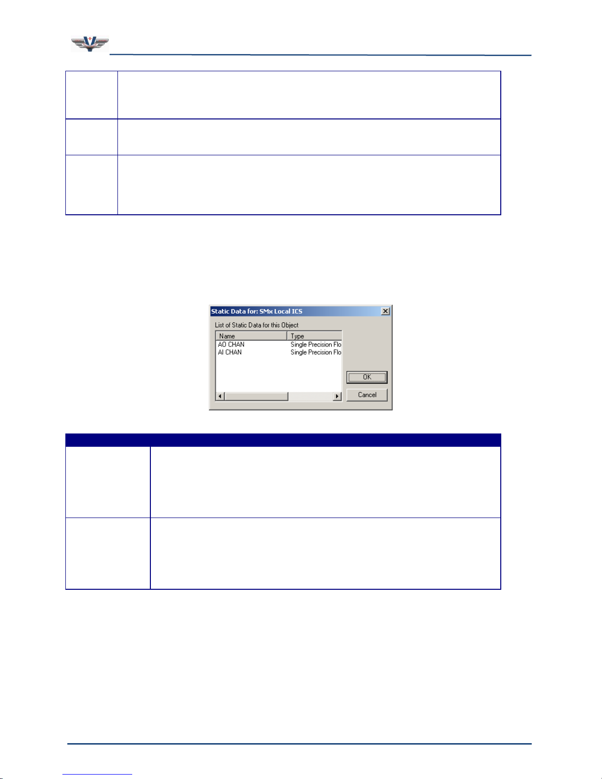
SMx Audio System User's Manual, V1.41
SimPhonics, Inc.
Page 65 of 77
Page 65 of 77
Copyright © 2014 SimPhonics, Incorporated, All Rights Reserved
VOL
VOLUME
This is the volume pin, and accepts floating-point values of attenuation
from 0 to 1.0, with 1.0 equal to no attenuation.
RX
RECEIVE ENABLE
Enables reception for this channel. You can use this to set for receive only.
TX
TRANSMIT ENABLE
Enables transmission on this channel. If TX enable is set TRUE, then
internally RX enable is set to TRUE for as long as TX is TRUE. After TX
goes back to FALSE, RX will go back to whatever value is at the RX pin.
STATIC DATA
DESCRIPTION
AI CHAN
ANALOG INPUT CHANNEL
This is the physical analog input channel to which your user’s input
is attached. You can change this value only when the system is not
executing. Changing the value during execution will have no effect
and this value will retain its previous value.
AO CHAN
ANALOG OUTPUT CHANNEL
This is the physical analog output channel to which your user’s input
is attached. You can change this value only when the system is not
executing. Changing the value during execution will have no effect
and this value will retain its previous value.
8.5.4 STATIC DATA
The object contains two static data elements for setting the input and output channel that
for the intercom. Each element sets the physical analog output and analog input connection
for the headset or other device that this object is assigned to.
There are some caveats that must be considered when using this object. First and
foremost, you must have at least one “SMx Analog In to Analog Out Mixer” device
port present in the project. The SMx device will not execute the “SMx Analog In to
Analog Out Mixer” if at least one port is not in the project. Note the sample screen shot
below.
8.5.5 SIDETONE
Page 66
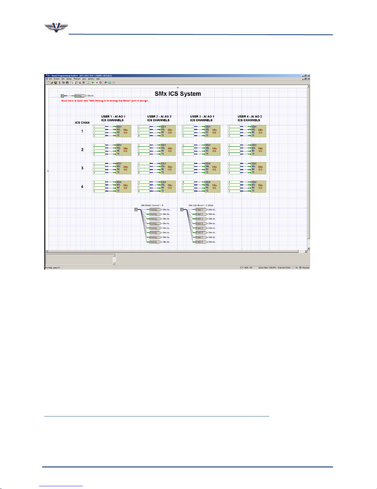
SMx Audio System User's Manual, V1.41
SimPhonics, Inc.
Page 66 of 77
Page 66 of 77
Copyright © 2014 SimPhonics, Incorporated, All Rights Reserved
You must enable your own sidetone via ports in V+, since this object does not compute the
sidetone for you. To setup sidetone, set the AI to AO port for your input and output
channel.
8.5.6 BE CAREFUL WHEN SETTING UP THE AI AND AO CHANNELS
Multiple ICS objects for the same AI and AO pair can be used to setup multiple ICS channels
for that user (AI and AO pair). However, an error will be generated if another ICS object
uses only one of the same AI or AO channels. In other words, another object must use the
same AI and AO or both AI and AO channel must be different numbers.
8.5.7 DO NOT USE MORE THAN ONE ICS WITH THE SAME PARAMETERS
Ensure you do not user more than one ICS object with the same AO, AI and ICS channel at
the same time in a design. This will result in only one of the objects with the same
parameters working properly. In most cases the controlling mechanism or GUI that is being
used to control the system will not allow a single user to have more than one ICS with the
same channel.
8.5.8 SAMPLE WORKSHEET
You can download the sample worksheet above from:
http://www.simphonics.com/library/VPLusSamples/SMx/LOCAL%20ICS/
Page 67
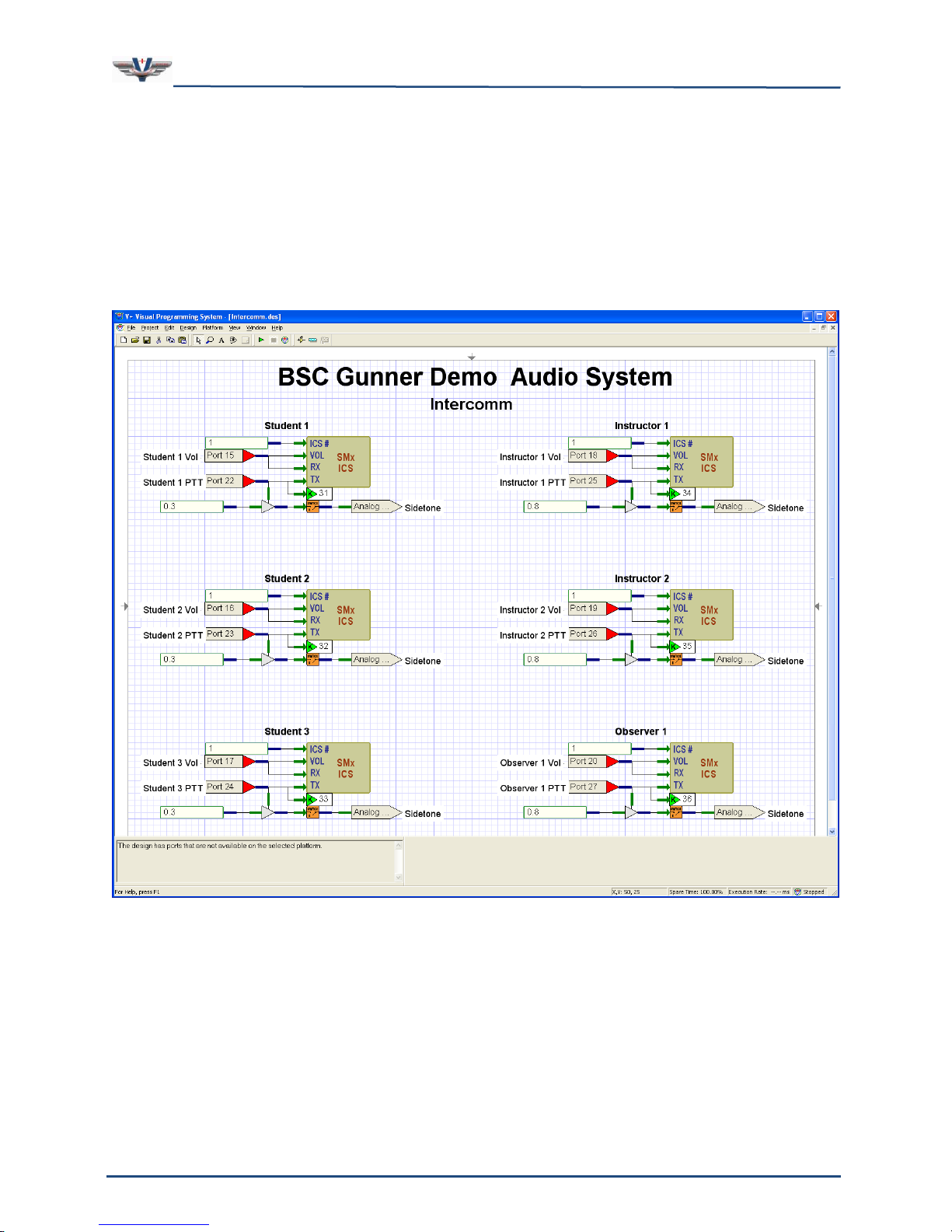
SMx Audio System User's Manual, V1.41
SimPhonics, Inc.
Page 67 of 77
Page 67 of 77
Copyright © 2014 SimPhonics, Incorporated, All Rights Reserved
8.5.9 PRACTICAL APPLICATION
The screenshot below shows a simple one channel intercom system for six stations. In this
case, there are three Students, two Instructors, and an Observer. Since this application did
not require more than one ICS channel, all ICS# pins were set to 1. Note the AI to AO port
under each ICS object to enable sidetone for a given station. Remember that the ICS object
does not provide sidetone. There are other functions on this worksheet that are application
specific.
Page 68
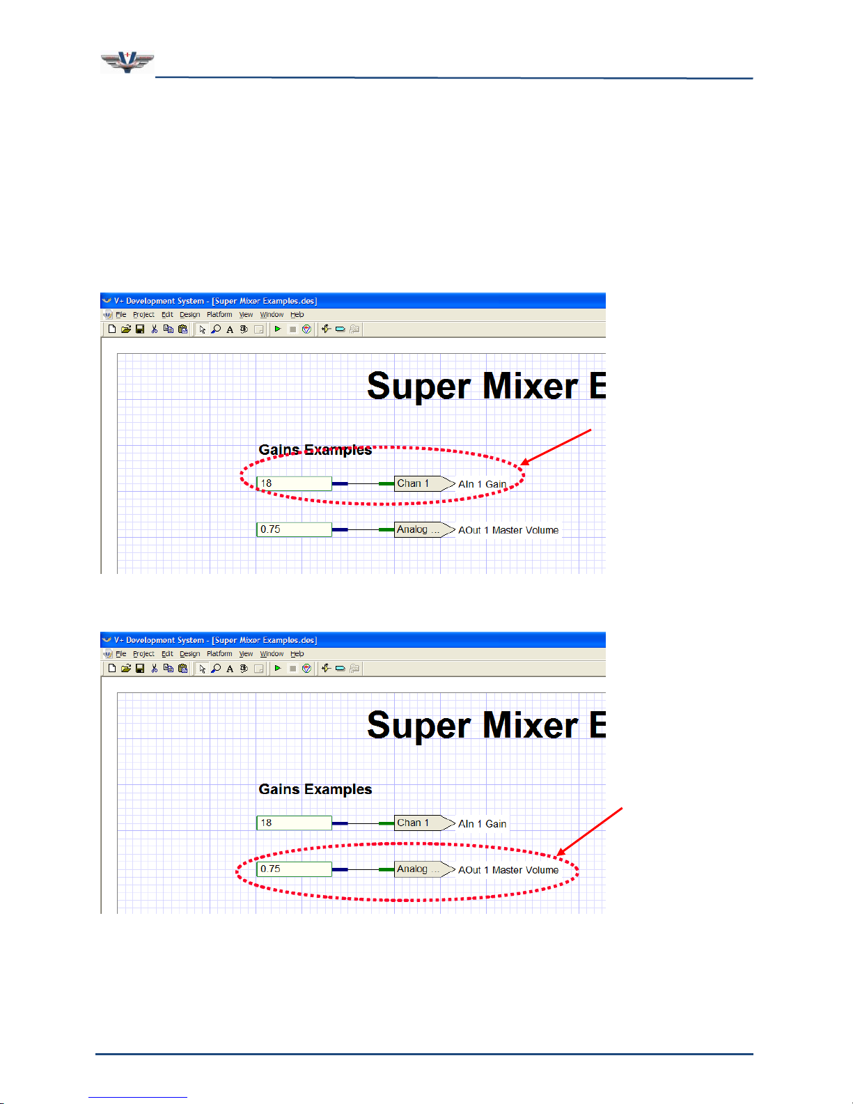
SMx Audio System User's Manual, V1.41
SimPhonics, Inc.
Page 68 of 77
Page 68 of 77
Copyright © 2014 SimPhonics, Incorporated, All Rights Reserved
AI Gain Boost
AO Master Volume
8.6 Super Mixer V+ Examples
The C:\Program Files\VPLus\VPLus Samples\Tutorials\SMx folder contains a design
worksheet called Super Mixer Examples.des which is shown in the following examples.
8.6.1 Controlling the Super Mixer’s Master Gains
Figure 41 highlights the AI Gain port for channel 1. It is set to a 18 dB gain boost, which is
pretty common for a headset microphone. Figure 42 highlights the AO Master Volume port
for channel 1. It is set to 0.75 which represents 75% of the maximum volume.
Figure 41, AI Gain Boost Example
Figure 42, AO Master Volume Example
Page 69
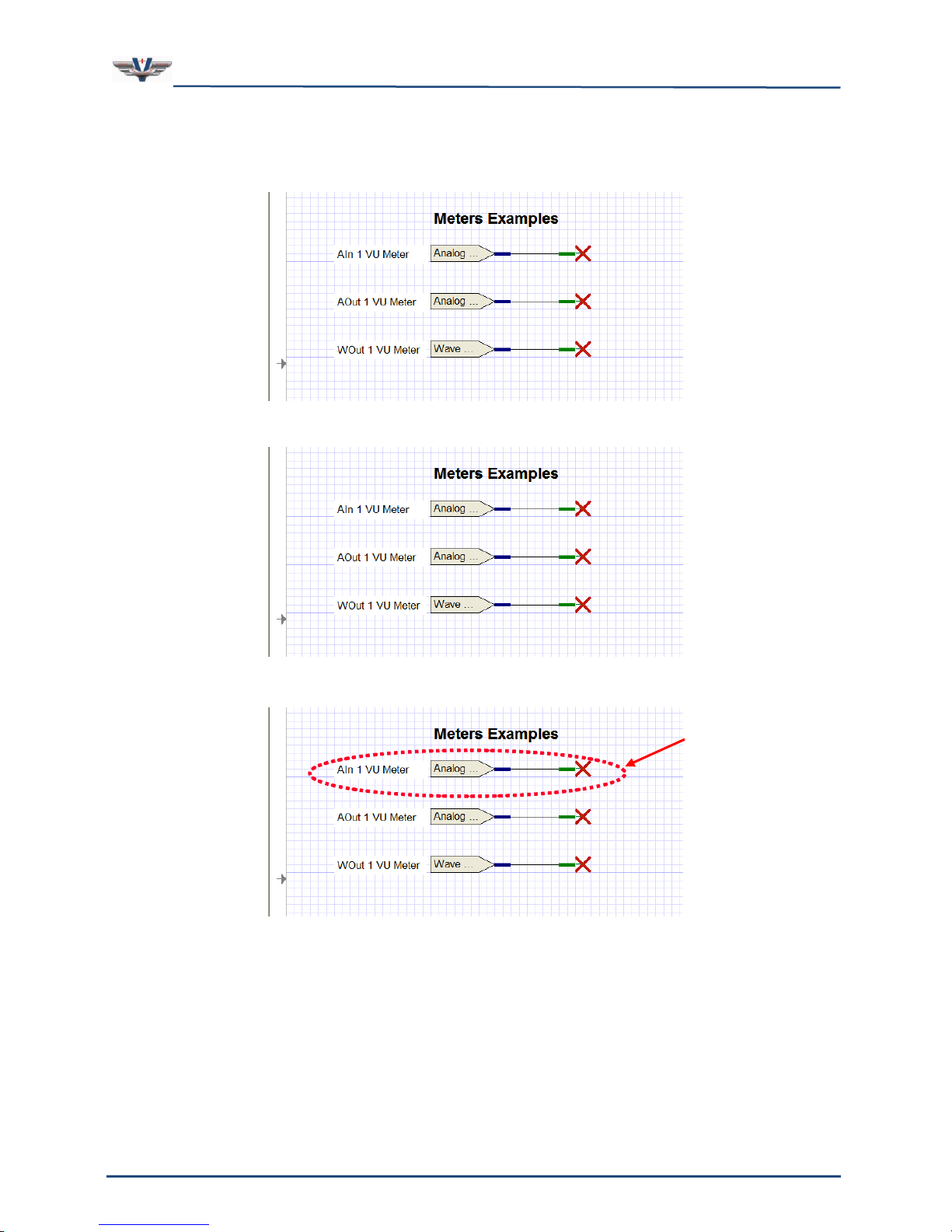
SMx Audio System User's Manual, V1.41
SimPhonics, Inc.
Page 69 of 77
Page 69 of 77
Copyright © 2014 SimPhonics, Incorporated, All Rights Reserved
AI VU Meter
8.6.2 Monitoring the Super Mixer’s Meters
Figure 43 highlights the VU Meter port for Analog In channel 1.
Figure 44 highlights the VU Meter Analog Out channel 1.
Figure 45 highlights the VU Meter port for Wave Out channel 1.
Figure 43, AI VU Meter Example
Page 70
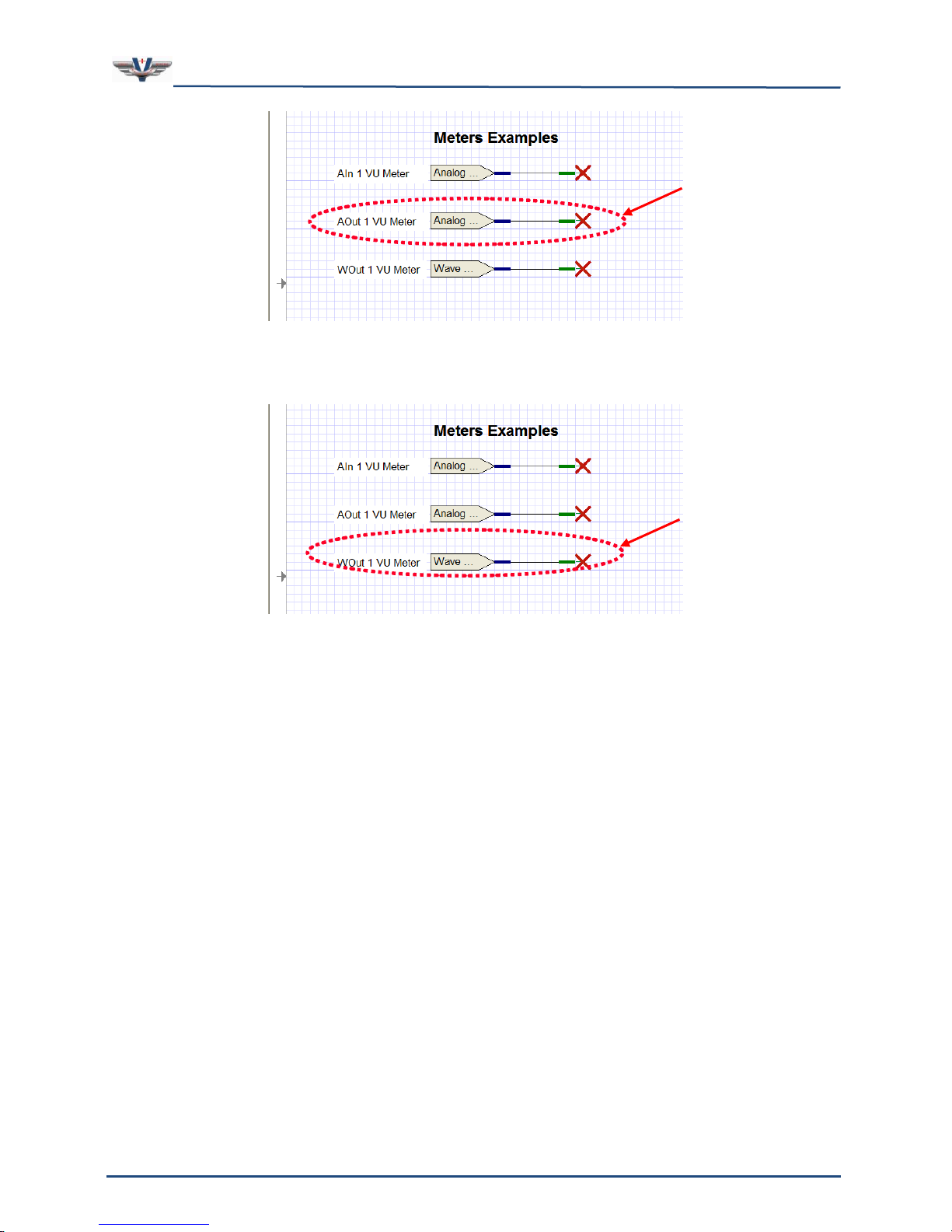
SMx Audio System User's Manual, V1.41
SimPhonics, Inc.
Page 70 of 77
Page 70 of 77
Copyright © 2014 SimPhonics, Incorporated, All Rights Reserved
AO VU Meter
WO VU Meter
Figure 44, AO VU Meter Example
Figure 45, WO VU Meter Example
Page 71
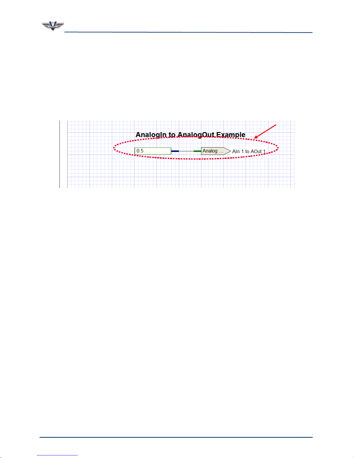
SMx Audio System User's Manual, V1.41
SimPhonics, Inc.
Page 71 of 77
Page 71 of 77
Copyright © 2014 SimPhonics, Incorporated, All Rights Reserved
AI to AO Mixing
8.6.3 Controlling the Super Mixer’s AI to AO Mixer
In order to pass an AI signal to an AO connector, you select the Analog In to Analog Out
Mixer device within V+. Then you select the port which represents the AI to AO connection
you wish to make. Figure 46 highlights an example of an AI to AO port. In this example, a
value of 0.5 is passed to the AI 1 to AO 1 port. Let’s say that in a communications
simulation, AI 1 and AO 1 are assigned to the pilot microphone and headphones
respectively. Feeding the pilot’s microphone signal to the pilot’s headphones would be done
to produce a sidetone, as is heard in an aircraft when the pilot engages the Push-To-Talk
(PTT) button.
Figure 46, Analog In to Analog Out Mixer Example
Page 72
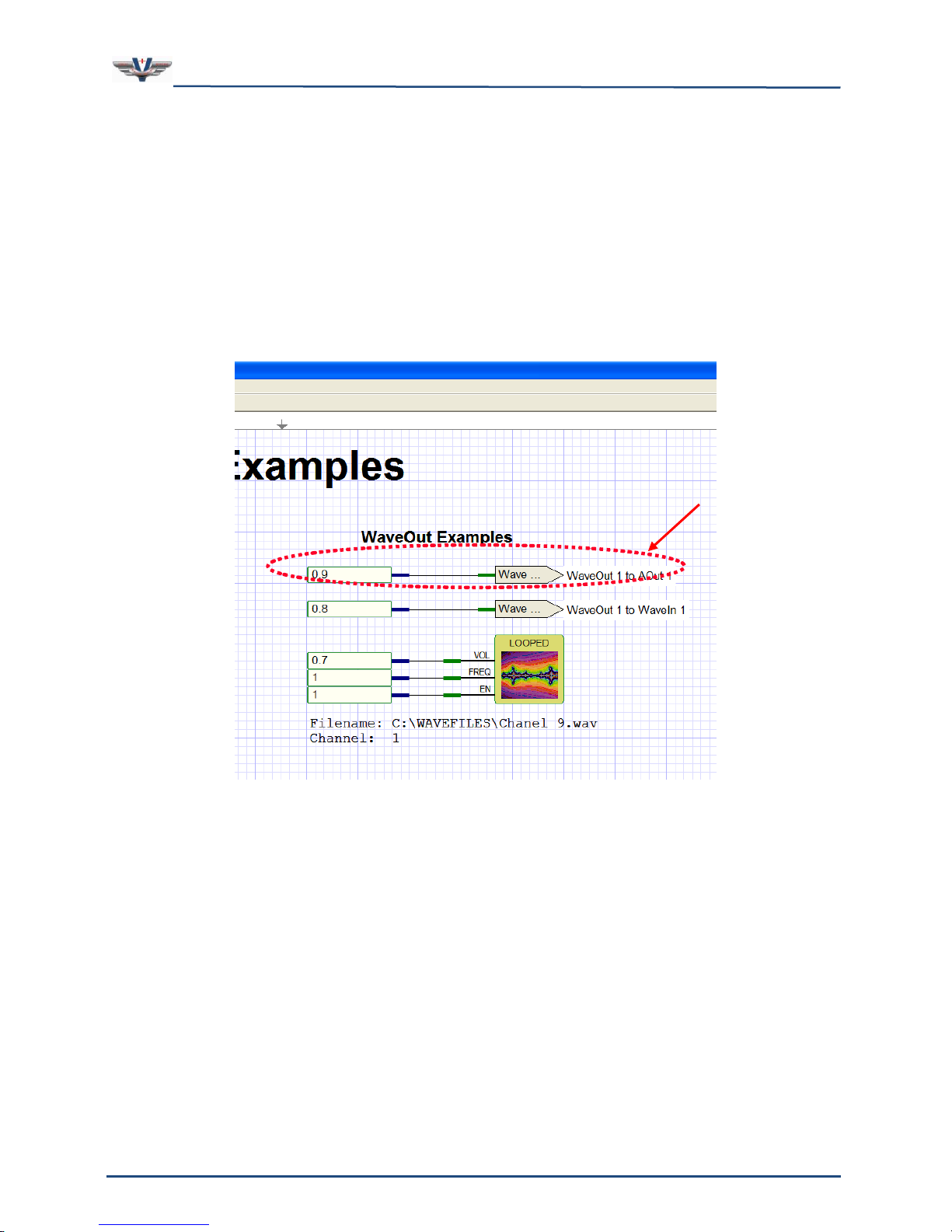
SMx Audio System User's Manual, V1.41
SimPhonics, Inc.
Page 72 of 77
Page 72 of 77
Copyright © 2014 SimPhonics, Incorporated, All Rights Reserved
WO to AO Mixing
8.6.4 Controlling the Super Mixer’s WO to AO Mixer
In order to pass a WO signal to an AO connector, you select the Wave Out Mixer device
within V+. Then you select the port which represents the WO to AO connection you wish to
make. Figure 47 highlights an example of an WO to AO port. In this example, a value of 0.9
is passed to the WO 1 to AO 1 port. Also shown in this example is a looped wave player with
a volume setting of 0.7, a frequency setting of 1, and the enable turned on. The static data
for the wave player is shown as a comment below it. The Channel 1 allocation indication
means that it is going to play on WO 1. Remember that this is only 1 wave player, and that
it is mixed only to AO channel 1. Any combination of WOs and AOs could be used. In fact
this one WO signal could be mixed to all AO output connectors by placing more ports on the
worksheet.
Figure 47, Wave Out to Analog Out Mixer Example
Page 73
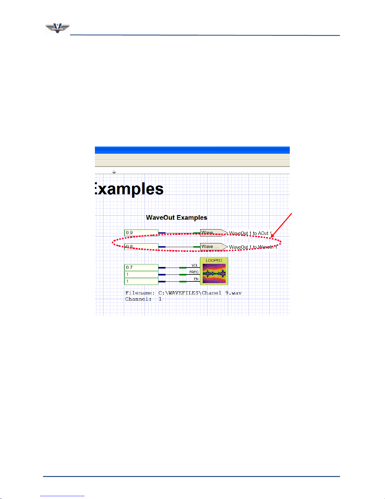
SMx Audio System User's Manual, V1.41
SimPhonics, Inc.
Page 73 of 77
Page 73 of 77
Copyright © 2014 SimPhonics, Incorporated, All Rights Reserved
WO to WI Mixing
8.6.5 Controlling the Super Mixer’s WO to WI Mixer
In order to pass a WO signal to an WI channel, you select the Wave Out to Wave In Mixer
device within V+. Then you select the port which represents the WO to WI connection you
wish to make. Figure 48 highlights an example of an WO to AO port. In this example, a
value of 0.8 is passed to the WO 1 to WI 1 port. Also shown in this example is a looped
wave player with a volume setting of 0.7, a frequency setting of 1, and the enable turned
on. The static data for the wave player is shown as a comment below it. The Channel 1
allocation indication means that it is going to play on WO 1. Remember that this is only 1
wave player, and that it is mixed only to WI channel 1. Any combination of WOs and WIs
could be used. In fact this one WO signal could be mixed to all WI channels by placing more
ports on the worksheet.
Figure 48, Wave Out to Wave In Mixer Example
Page 74
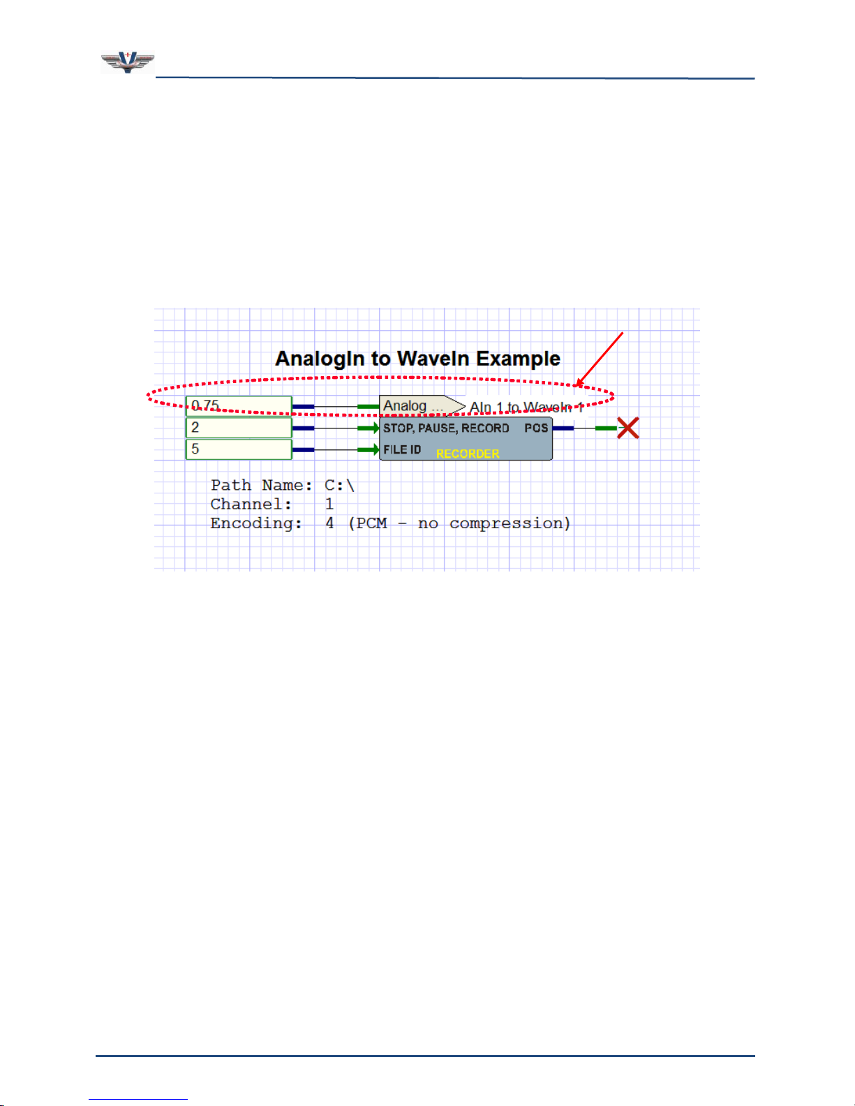
SMx Audio System User's Manual, V1.41
SimPhonics, Inc.
Page 74 of 77
Page 74 of 77
Copyright © 2014 SimPhonics, Incorporated, All Rights Reserved
AI to WI Mixing
8.6.6 Controlling the Super Mixer’s AI to WI Mixer
In order to pass an AI signal to a WI channel, you select the Wave In Mixer device within
V+. Then you select the port which represents the AI to WI connection you wish to make.
Figure 49 highlights an example of an AI to WI port. In this example, a value of 0.75 is
passed to the AI 1 to WI 1 port. Also shown in this example is a recorder with the STOP,
PAUSE, RECORD pin set to 2 (record) and the FILE ID pin set to 1. The static data for the
recorder is shown as a comment below it. The Channel 1 allocation indication means that it
is going to record to WI 1. Remember that this is only 1 recorder, and that it is mixed only
to WI channel 1. Any combination of AIs and WIs could be used. In fact this one AI signal
could be mixed to all WI channels by placing more ports on the worksheet.
Figure 49, Analog In to Wave In Mixer Example
Page 75
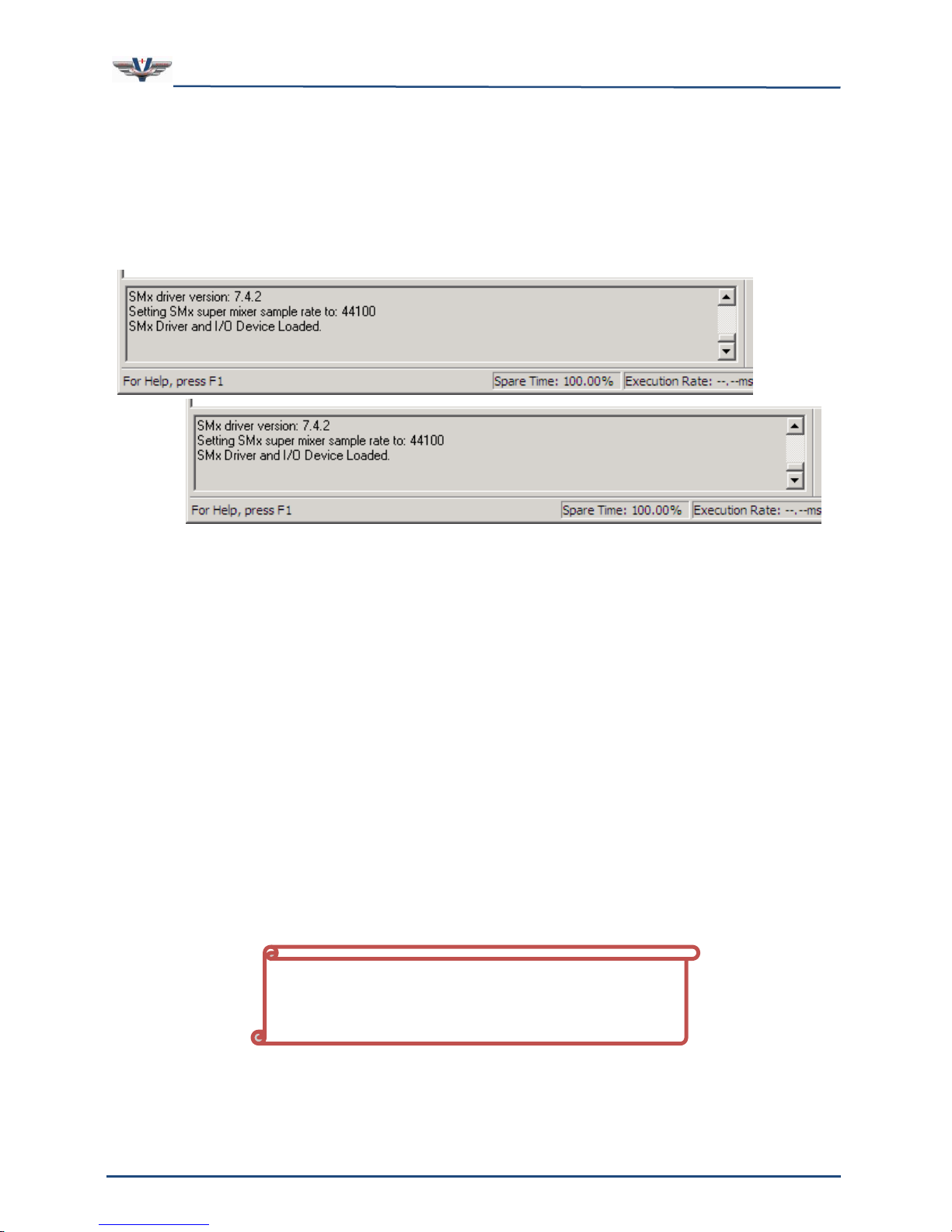
SMx Audio System User's Manual, V1.41
SimPhonics, Inc.
Page 75 of 77
Page 75 of 77
Copyright © 2014 SimPhonics, Incorporated, All Rights Reserved
If the power to the BOB is ever turned off
while the system is running, the SMx must be
rebooted.
8.7 Run-Time Messages
The V+ Run Time System window has a scrollable message list which provides the user with
useful information. Pay attention to this message list for error messages if your system
stops or isn’t working. A typical output of the message windows would look something as
shown in Figure 47.
Figure 50
Figure 50, Run Time System Message Window
9 Troubleshooting
This section helps resolve “system” problems without incurring return costs and down time.
Retrieve the delivered documentation packages provided with your unit, and refer to your
Hardware and Software Configuration Documents. Verify all BIOS settings exactly match
your delivered documentation. Verify all hardware switch settings and jumpers match your
documentation. If the above are verified; reload* (or ColdBoot) the system software by
following the procedure provided in your manuals. This will completely rebuild your system
to original Factory settings.
9.1 Common Problems with Power
One of the most common problems faced by users of the SMx system is that the breakout
box, BOB, is sometimes powered from a separate source than the chassis. The power to the
breakout box cannot be turned off and back on while the SMx is running, or the system will
lose synchronization, and very strange things will happen. Sometimes the situation will
recover, sometimes not, and usually not.
Page 76

SMx Audio System User's Manual, V1.41
SimPhonics, Inc.
Page 76 of 77
Page 76 of 77
Copyright © 2014 SimPhonics, Incorporated, All Rights Reserved
*Warning: Cold Booting/Reloading systems removes all changes made by the Buyer;
please backup any modifications you wish to save.
9.2 System Power Supply
If the green power LED is blinking on the front panel of a breakout box, this indicates that
there is a fault in the breakout box power supply. Note that the main power plug of the
breakout box is the only way to completely remove power from the breakout box.
9.3 Safety
The following safety precautions must be observed at all times for proper use of the system.
Make sure all electrical cords are disconnected from the SMx system before removing,
handling, or replacing any components,
Make sure to open all system computer chassis PRIOR to applying power. This is to ensure
that no damage occurred during shipment. Verify all cards are well seated in their slots, and
all power and drive connections are good.
9.4 Handling Your System
The SMx system components are sensitive to electrostatic discharge (ESD). Make sure you
are properly grounded when handling an SMx system or its internal components.
SimPhonics is not responsible for any defect or damage caused by improper installation,
modification, misuse, neglect, inadequate maintenance, and accidents, or for any product
that has been repaired or altered by anyone other than SimPhonics. SimPhonics, Inc. also
shall have no responsibility for any damage, which may occur during shipment of returned
equipment for repair. The warranty will be invalid if any alterations are made to the circuitry
or the hardware components, or if 3rd party software programs have been installed onto the
unit. Damage due to static discharges or application of excessive voltages will void the
warranty.
9.5 Warranty & RMA Information
SimPhonics products are warranted against defects in materials and workmanship for up to
one year. System warranties are effective from the date of system ATP. Single product
purchases are warranted from the date of shipment. SimPhonics, Inc. will repair or replace,
at its option, any product found to be defective during the warranty period. See our website
for additional information on the SMx Warranty. SimPhonics makes every effort to provide
you with the highest quality products available. If you encounter a problem and need to
return your equipment, you will need to obtain an RMA number. This is done by completing
an RMA form. Before filling out an RMA form you should have the following information
available:
Serial number of part in question
Part number of part in question
The name of a contact at your company
A description of the problem with the equipment
Date of delivery
Page 77

SMx Audio System User's Manual, V1.41
SimPhonics, Inc.
Page 77 of 77
Page 77 of 77
Copyright © 2014 SimPhonics, Incorporated, All Rights Reserved
Contact Information
Corporate Office:
SimPhonics, Inc.
3226 N. Falkenburg Road
Tampa, FL 33619
Shipping & Receiving:
SimPhonics, Inc.
3226 N. Falkenburg Road
Tampa, FL 33619
Telephone:
(813) 623-9917
Facsimile:
(813) 623-5119
General Information:
[email protected]
Internet:
[email protected]
Business Hours:
Monday-Friday
8:00 a.m. - 5:00 p.m.
(Except on major holidays)
9.5.1 Requesting an RMA Number
To request an RMA number, complete the online RMA form found on our website. For more
information about RMAs visit our website:
http://www.simphonics.com/supp/rma/instructions.htm
9.6 Contact Information
SimPhonics is committed to providing quality round-the-clock customer support. Below is a
list of contact information should you need to speak to someone in our office. Additionally,
our website is available 24 hours a day, seven days a week and, contains a comprehensive
list of support services including technical documents, online manuals, tutorials, help
systems, and much more. Visit our website’s support link for more information.
 Loading...