

Page 1

Freeway
®
1200/1300
Hardware Installation Guide
DC 900-1537B
Simpact, Inc.
9210 Sky Park Court
San Diego, CA 92123
November 1999
Page 2

Simpact, Inc.
9210 Sky Park Court
San Diego, CA 92123
(858) 565-1865
Freeway 1200/1300 Hardware Installation Guide
© 1999 Simpact, Inc. All rights reserved
Printed in the United States of America
This document can change without notice. Simpact, Inc. accepts no liability for any errors this
document might contain.
Freeway is a registered trademark of Simpact, Inc.
All other trademarks and trade names are the properties of their respective holders.
Page 3

Contents
List of Figures 5
List of Tables 7
Preface 9
Safety Precautions 15
Freeway 1200 Certifications 21
Freeway 1300 Certifications 25
1 Getting Started 29
2 Hardware Installation 31
3 Configuring the Boot Parameters using the Initialization Disk 43
4 Configuring the Boot Parameters using the Local Console 51
A Electrical Interfaces 61
B Freeway 1300 LED Panel and Alarm Functions 63
C Replacing the Power Supply in a Freeway 1300 67
Index 71
DC 900-1537B
3
Page 4

4
Freeway 1200/1300 Hardware Installation Guide
DC 900-1537B
Page 5

List of Figures
Figure 2–1: Front View: Freeway 1200 (lockable door not shown) ........... 34
Figure 2–2: Front View: Freeway 1300 (lockable door not shown) ........... 35
Figure 2–3: Example Back View: Freeway 1200 ..................... 36
Figure 2–4: Example Back View: Freeway 1300 ..................... 37
Figure 2–5: ICP Numbering: Freeway 1200 ....................... 39
Figure 2–6: ICP Numbering: Freeway 1300 ....................... 40
Figure 3–1: Example of the Freeway System Boot Parameters ............. 45
Figure 3–2: Configured Freeway System Boot Parameters ............... 48
Figure 4–1: Freeway Boot System Main Menu ...................... 54
Figure 4–2: Example of the Freeway System Boot Parameters ............. 55
Figure 4–3: Configured Freeway Boot Parameters.................... 60
Figure B–1: Front Panel: Freeway 1300 (lockable door not shown)........... 63
DC 900-1537B
5
Page 6

6
Freeway 1200/1300 Hardware Installation Guide
DC 900-1537B
Page 7

List of Tables
Table 3–1: Freeway System Boot Parameters....................... 45
Table 3–2: Flags for Reset Action............................. 47
Table 4–1: Freeway System Boot Parameters....................... 56
Table 4–2: Flags for Reset Action............................. 58
Table A–1: Commonly Used Electrical Interfaces .................... 61
DC 900-1537B
7
Page 8

8
Freeway 1200/1300 Hardware Installation Guide
DC 900-1537B
Page 9

Preface
The “Required
Equipment”
section was
intentionally
moved to
Chapter 2.
4/20/99: I
changed the
i
Purpose of Document
This document describes the hardware installation procedures for Simpact’s Freeway
1200/1300 communications server. It is used in conjunction with the Freeway User
Guide , which describes the software installation procedure.
Intended Audience
This document should be read by the computer technician who will be installing the
Freeway communications server. System administrators and system integrators may
also find it useful.
Organization of Document
The “Safety Precautions” section on page 15 describes important safety guidelines that
you should review before beginning the installation.
The “Freeway 1200 Certifications” section on page 21 shows the certifications for the
Same:
3100/3150,
3200/7200,
1200/1300
Freeway 1200.
The “Freeway 1300 Certifications” section on page 25 shows the certifications for the
Freeway 1300.
Chapter 1 is an overview of the Freeway installation procedure.
Chapter 2 describes the hardware installation.
DC 900-1537B
9
Page 10

10
Freeway 1200/1300 Hardware Installation Guide
Chapter 3 describes how to configure the boot parameters using the boot parameter
initialization disk.
Chapter 4 describes how to configure the boot parameters using the local console.
Appendix A shows the commonly used electrical interfaces.
Appendix B describes the Freeway 1300 LED panel and alarm functions.
Appendix C describes how to replace a power supply in the Freeway 1300.
10/19/99
Leslie: Add
1566
Addendum to
1501, and add
“Freeway” to
title of 1533.
Simpact References
The following general product documentation list is to familiarize you with the avail-
able Simpact Freeway and embedded ICP products. The applicable product-specific
reference documents are mentioned throughout each document (also refer to the
“readme” file shipped with each product). Most documents are available on-line at
Simpact’s web site, www.simpact.com.
General Product Overviews
•
Freeway 1100 Technical Overview
Freeway 2000/4000/8800 Technical Overview
•
•
ICP2432 Technical Overview
•
ICP6000X Technical Overview
Hardware Support
Freeway 1100/1150 Hardware Installation Guide
•
•
Freeway 1200/1300 Hardware Installation Guide
Freeway 2000/4000 Hardware Installation Guide
•
•
Freeway 8800 Hardware Installation Guide
•
Freeway ICP6000R/ICP6000X Hardware Description
•
ICP6000(X)/ICP9000(X) Hardware Description and Theory of
Operation
•
ICP2424 Hardware Description and Theory of Operation
25-000-0419
25-000-0374
25-000-0420
25-000-0522
DC-900-1370
DC-900-1537
DC-900-1331
DC-900-1553
DC-900-1020
DC-900-0408
DC-900-1328
DC 900-1537B
Page 11

Preface
•
ICP2432 Hardware Description and Theory of Operation
•
ICP2432 Electrical Interfaces (Addendum to DC-900-1501)
•
ICP2432 Hardware Installation Guide
DC-900-1501
DC-900-1566
DC-900-1502
Freeway Software Installation and Configuration Support
Freeway Message Switch User Guide
•
Freeway Release Addendum: Client Platforms
•
•
Freeway User Guide
Freeway Loopback Test Procedures
•
DC-900-1588
DC-900-1555
DC-900-1333
DC-900-1533
Embedded ICP Software Installation and Programming Support
ICP2432 User Guide for Digital UNIX
•
•
ICP2432 User Guide for OpenVMS Alpha
•
ICP2432 User Guide for OpenVMS Alpha (DLITE Interface)
•
ICP2432 User Guide for Solaris STREAMS
ICP2432 User Guide for Windows NT
•
•
ICP2432 User Guide for Windows NT (DLITE Interface)
DC-900-1513
DC-900-1511
DC-900-1516
DC-900-1512
DC-900-1510
DC-900-1514
Application Program Interface (API) Programming Support
•
Freeway Data Link Interface Reference Guide
•
Freeway Transport Subsystem Interface Reference Guide
•
QIO/SQIO API Reference Guide
DC-900-1385
DC-900-1386
DC-900-1355
Socket Interface Programming Support
Freeway Client-Server Interface Control Document
•
Toolkit Programming Support
Freeway Server-Resident Application and Server Toolkit
•
Programmer Guide
OS/Impact Programmer Guide
•
Protocol Software Toolkit Programmer Guide
•
Protocol Support
ADCCP NRM Programmer Guide
•
•
Asynchronous Wire Service (AWS) Programmer Guide
DC 900-1537B
DC-900-1303
DC-900-1325
DC-900-1030
DC-900-1338
DC-900-1317
DC-900-1324
11
Page 12

Freeway 1200/1300 Hardware Installation Guide
12
•
AUTODIN Programmer Guide
•
Bit-Stream Protocol Programmer Guide
•
BSC Programmer Guide
•
BSCDEMO User Guide
BSCTRAN Programmer Guide
•
DDCMP Programmer Guide
•
•
FMP Programmer Guide
•
Military/Government Protocols Programmer Guide
•
N/SP-STD-1200B Programmer Guide
SIO STD-1300 Programmer Guide
•
•
X.25 Call Service API Guide
X.25/HDLC Configuration Guide
•
X.25 Low-Level Interface
•
Document Conventions
The term “Freeway” refers to either of the Freeway models, 1200 or 1300.
DC-908-1558
DC-900-1574
DC-900-1340
DC-900-1349
DC-900-1406
DC-900-1343
DC-900-1339
DC-900-1602
DC-908-1359
DC-908-1559
DC-900-1392
DC-900-1345
DC-900-1307
Revision History
The revision history of the Freeway 1200/1300 Hardware Installation Guide , Simpact
document DC 900-1537B, is recorded below:
Document Revision Release Date Description
DC 900-1537A July 1999 Original release
DC 900-1537B November 1999 Added new flag, 0x2000
Added description of Freeway 1300
LED panel and alarm functions
DC 900-1537B
Page 13

Customer Support
If you are having trouble with any Simpact product, call us at 1-800-275-3889 Monday
through Friday between 8 a.m. and 5 p.m. Pacific time.
You can also fax your questions to us at (858)560-2838 or (858)560-2837 any time.
Please include a cover sheet addressed to “Customer Service.”
We are always interested in suggestions for improving our products. You can use the
report form in the back of this manual to send us your recommendations.
Preface
DC 900-1537B
13
Page 14

Freeway 1200/1300 Hardware Installation Guide
14
DC 900-1537B
Page 15

Safety Precautions
English
Be sure to take the following safety precautions during installation and maintenance of
the Freeway communications server:
• Observe the warnings and directions printed on the Freeway server and its asso-
ciated equipment.
• Check the electrical rating label on the Freeway chassis. Be sure that the voltage
and frequency of your power source match this rating.
• The Freeway server must be plugged into a grounded, three-wire power outlet.
Do not use an adapter that permits a three-wire electrical cord to be plugged into
a two-wire power outlet.
• Use appropriately rated extension cords or power strips only.
• To ensure proper cooling, always operate the Freeway server with its covers in
place. Do not cover or block any of the openings on the Freeway chassis. Do not
place the unit near a heater.
• Do not insert objects through openings in the Freeway chassis. Doing so could
result in a short circuit that might cause a fire or an electric shock.
• Do not modify the Freeway equipment in any way. Simpact, Inc. is not responsi-
ble for regulatory compliance of any Freeway communications server that has
been modified. Altering the Freeway enclosure in any way other than the installa-
tion of Simpact-provided options may invalidate Freeway’s safety certifications.
DC 900-1537B
15
Page 16

Freeway 1200/1300 Hardware Installation Guide
• Always unplug the Freeway AC power cord before removing the top or bottom
covers for servicing.
Français
Précautions d
Nous vous prions de suivre les précautions d’emploi suivantes au cours de l’installation
ou de tout entretien de votre serveur de communication Freeway:
’emploi
• Respecter les avertissements et les instructions imprimées sur le serveur Freeway
et les appareils qui y sont associés.
• Vérifier les normes électriques indiquées sur une étiquette se trouvant sur le châs-
sis Freeway. Prière de s’assurer que le voltage et la fréquence de la source d’alimen-
tation sont compatibles avec ces normes.
• Le serveur Freeway doit être branché dans une prise de terre à trois broches. Ne
pas utiliser d’adaptateur permettant de brancher une prise mâle à trois broches
dans une prise de courant à deux broches.
• N’utiliser des rallonges, fils électriques ou parasurtenseurs qu’aux normes appro-
priées.
• Afin de refroidir correctement le serveur Freeway, utiliser seulement celui-ci avec
la housse en place. Ne pas couvrir ou bloquer les ouvertures du châssis Freeway.
Ne pas placer l’appareil Freeway près d’une source de chaleur.
• Ne pas insérer d’objets par les ouvertures du châssis Freeway. Ceci risquerait de
provoquer un court-circuit résultant en une décharge ou un incendie.
• Ne pas modifier l’appareil Freeway de quelque manière que ce soit. Simpact, Inc.
ne pourra être tenu responsable de toute infraction aux normes d’un serveur de
communication Freeway ayant été modifié. Toute altération de l’enveloppe Free-
way d’une manière autre que pour l’installation d’options fournies par Simpact
risque de rendre les normes de sécurité de Freeway invalides.
16 DC 900-1537B
Page 17

Safety Precautions
• Toujours débrancher le fil d’alimentation en courant alternatif de Freeway avant
d’enlever la housse supérieure ou inférieure à des fins d’entretien.
Deutsch
Sicherheitsvorkehrungen
Vergewissern Sie sich, daß die folgenden Sicherheitsmaßnahmen bei der Installation
und Wartung des Freeway Kommunikations-Servers eingehalten werden:
• Lesen Sie die Anleitung und Sicherheitsregeln auf dem Freeway Server und auf
dem Zubehör.
• Die Voltspannung und Frequenz der von Ihnen verwendeten Stromquelle muß
mit den elektrischen Werten, die auf dem Freeway Chassis angegeben sind, übere-
instimmen.
• Der Freeway Server muß an eine geerdete, dreiadrige Stromquelle angeschlossen
werden. Bitte verwenden Sie keine Adapter, die den Anshluß dreiadriger Kabel an
zweiadrige Stromquellen ermöglichen.
• Benutzen Sie nur den Angaben entsprechende Verlängerungskabel oder Steck-
dosenleisten.
• Benutzen Sie den Freeway Server nur, wenn alle Abdeckungen intakt sind und die
vordere Scharniertür geschlossen ist. Blockieren Sie in keiner Weise irgendwelche
Öffnungen des Freeway Chassis, und positionieren Sie den Apparat nicht in der
Nähe einer Heizung.
• Stecken Sie keine Gegenstände durch die Öffnungen des Gehäuses; dies könnte
einen Kurzschluß hervorrufen, der einen Brand oder einen elektrischen Schlag
verursachen kann.
• Verändern Sie in keiner Weise das Freeway Zubehör. Simpact, Inc. ist nicht für
abgeänderte Freeway Kommunikations-Server verantwortlich, die demzufolge
den vorgeschriebenen Regeln nicht entsprechen. Jegliche Abänderungen der
DC 900-1537B 17
Page 18

Freeway 1200/1300 Hardware Installation Guide
Freeway Anlage, mit Ausnahme der Installation von Simpact-Sonderausstattun-
gen, können die Sicherheitsbescheinigung der Anlage ungültig werden lassen.
• Entfernen Sie immer das Freeway Stromkabel von der Stromquelle, bevor Sie die
oberen oder unteren Deckel zur Wartung abnehmen.
Italiano
Norme di sicurezza
Durante l’installazione e la manutenzione del server per le comunicazioni Freeway
seguire le seguenti norme di sicurezza:
• Seguire le avvertenze e le istruzioni stampate sul server Freeway e sulle altre unità
ad esso collegate;
• Controllare l’etichetta con l’indicazione del voltaggio elettrico sul telaio ed assi-
curarsi che voltaggio e frequenza della presa di corrente vi corrispondano;
• Il server Freeway deve essere collegato ad una spina con messa a terra, e con tre
fili. Non usare un adattatore che consente di collegare un filo a tre fili in una presa
a due;
• Usare solo fili e prese multiple con taratura appropriata;
• Per assicurare un raffreddamento adeguato usare sempre il server Freeway con il
suo relativo coperchio. Non coprire o bloccare nessuna delle aperture del telaio di
Freeway. Non collocare l’unità vicino a fonti di calore;
• Non inserire oggetti nelle aperture situate sul telaio di Freeway, perchè così
facendo si rischia di provocare un corto circuito, che può generare un incendio o
una scossa elettrica;
• Non modificare in nessun modo l’unità Freeway. La Simpact, Inc. non è respons-
abile della conformità alle norme di nessun server Freeway per le comunicazioni
che sia stato modificato. L’alterazione in qualsiasi maniera del telaio di Freeway,
18 DC 900-1537B
Page 19

Safety Precautions
che differisca dalle opzioni di installazione fornite dalla Simpact, può invalidare le
garanzie di sicurezza;
• Prima di togliere il coperchio o la base per effettuare qualsiasi manutenzione,
togliere sempre la spina di Freeway.
DC 900-1537B 19
Page 20

Freeway 1200/1300 Hardware Installation Guide
20 DC 900-1537B
Page 21

Freeway 1200 Certifications
The Freeway 1200 meets or exceeds the following standards:
Safety
UL 1950, CSA-C22.2 No. 950, and EN60950
Emissions
FCC US 47 CFR Part 15, Subpart B, and EN55022 (both to Class A)
Immunity
EN 50082-1 (1992)
The Freeway 1200 has been tested and found to comply with the limits for a Class A dig-
ital device, pursuant to Part 15 of the FCC Rules. These limits are designed to provide
reasonable protection against harmful interference when the equipment is operated in
a commercial environment. The Freeway 1200 generates, uses, and can radiate radio
frequency energy and, if not installed and used in accordance with the instruction man-
ual, may cause harmful interference to radio communications. Operation of this equip-
ment in a residential area is likely to cause harmful interference in which case the user
will be required to correct the interference at his own expense.
DC 900-1537B 21
Page 22

Freeway 1200/1300 Hardware Installation Guide
EC Declaration of Conformity for the Freeway 1200
We: Simpact, Inc.
9210 Sky Park Court
San Diego, CA 92123
declare under sole responsibility that the
Freeway 1200, Model FW-1200, P/N LM-1200
to which this declaration relates, meet the essential health and safety requirements
and are in conformity with the relevant section of the following EC standards and other
normative documents:
EU EMC Directives and Amendments 89/336/EEC and 93/68/EEC
Essential health and safety requirements relating to electromagnetic compatibility:
EN 55022 Class A
and CISPR 22A
EN 55022 Class A Radiated emissions
EN 55022 Class A Conducted emissions
EN 50082-1 (1992) EC generic immunity requirements, Category A & B
IEC 1000-4-2 Electrostatic discharge requirements for industrial process
IEC 1000-4-3 Radiated electromagnetic field requirements for industrial
IEC 1000-4-4 Electrical Fast Transients for industrial process measurement
Limits and methods of measurements of Radio Interference
characteristics of information technology equipment
measurement and control equipment
process measurement and control equipment
and control equipment
22 DC 900-1537B
Page 23
Freeway 1200 Certifications
EC Low Voltage Directive 73/23/EEC
Essential health and safety requirements relating to electrical equipment designed for
use within certain voltage limits:
EN 60950 Safety requirements of information technology equipment including
electrical machines
The Freeway 1200 complies with all safety relevant provisions referring to:
• Protection against electrical hazards
• Protection against other hazards such as:
• mechanical hazards
• fire hazards
• noise
• vibration
The safety issues of this information technology equipment have been evaluated by
government-accredited European organizations such as TUV Product Services, Inc.
and Intertek Testing Services.
The CE marking has been affixed on the device according to article 10 of the EC Direc-
tive 89/336/EEC.
Eric Loos
Vice President of Technology
DC 900-1537B 23
Page 24

Freeway 1200/1300 Hardware Installation Guide
24 DC 900-1537B
Page 25

Freeway 1300 Certifications
The Freeway 1300 meets or exceeds the following standards:
Safety
UL 1950, CSA-C22.2 No. 950, and EN60950
Emissions
FCC US 47 CFR Part 15, Subpart B, and EN55022 (both to Class A)
Immunity
EN 50082-1 (1992)
The Freeway 1300 has been tested and found to comply with the limits for a Class A dig-
ital device, pursuant to Part 15 of the FCC Rules. These limits are designed to provide
reasonable protection against harmful interference when the equipment is operated in
a commercial environment. The Freeway 1300 generates, uses, and can radiate radio
frequency energy and, if not installed and used in accordance with the instruction man-
ual, may cause harmful interference to radio communications. Operation of this equip-
ment in a residential area is likely to cause harmful interference in which case the user
will be required to correct the interference at his own expense.
DC 900-1537B 25
Page 26

Freeway 1200/1300 Hardware Installation Guide
EC Declaration of Conformity for the Freeway 1300
We: Simpact, Inc.
9210 Sky Park Court
San Diego, CA 92123
declare under sole responsibility that the
Freeway 1300, Model FW-1300, P/N LM-1300
to which this declaration relates, meet the essential health and safety requirements
and are in conformity with the relevant section of the following EC standards and other
normative documents:
EU EMC Directives and Amendments 89/336/EEC and 93/68/EEC
Essential health and safety requirements relating to electromagnetic compatibility:
EN 55022 Class A
and CISPR 22A
EN 55022 Class A Radiated emissions
EN 55022 Class A Conducted emissions
EN 50082-1 (1992) EC generic immunity requirements, Category A & B
IEC 1000-4-2 Electrostatic discharge requirements for industrial process
IEC 1000-4-3 Radiated electromagnetic field requirements for industrial
IEC 1000-4-4 Electrical Fast Transients for industrial process measurement
Limits and methods of measurements of Radio Interference
characteristics of information technology equipment
measurement and control equipment
process measurement and control equipment
and control equipment
26 DC 900-1537B
Page 27

Freeway 1300 Certifications
EC Low Voltage Directive 73/23/EEC
Essential health and safety requirements relating to electrical equipment designed for
use within certain voltage limits:
EN 60950 Safety requirements of information technology equipment including
electrical machines
The Freeway 1300 complies with all safety relevant provisions referring to:
• Protection against electrical hazards
• Protection against other hazards such as:
• mechanical hazards
• fire hazards
• noise
• vibration
The safety issues of this information technology equipment have been evaluated by
government-accredited European organizations such as TUV Product Services, Inc.
and Intertek Testing Services.
The CE marking has been affixed on the device according to article 10 of the EC Direc-
tive 89/336/EEC.
Eric Loos
Vice President of Technology
DC 900-1537B 27
Page 28

Freeway 1200/1300 Hardware Installation Guide
28 DC 900-1537B
Page 29

Chapter
Getting Started
1
This manual describes how to install the Freeway 1200/1300 hardware and configure
the boot parameters. The following is a summary of the complete installation proce-
dure:
1. Install the hardware as described in Chapter 2 of this manual.
2. Install the software onto the boot server as described in the Freeway User Guide.
3. If you are using the boot parameter initialization disk, configure the boot param-
eters as described in Chapter 3 of this manual.
4. If you are using a local console, configure the boot parameters as described in
Chapter 4 of this manual.
5. Boot the Freeway server.
6. Run the loopback test as described in the Freeway Loopback Test Procedures.
7. Customize your installation, if necessary, as described in the Freeway User Guide.
8. Familiarize yourself with Freeway operations as described in the Freeway User
Guide.
DC 900-1537B 29
Page 30

Freeway 1200/1300 Hardware Installation Guide
30 DC 900-1537B
Page 31

Chapter
2
Hardware Installation
These are
generally the
same:
3100/3150,
3200/7200
This chapter describes how to set up the Freeway communications server and connect
it to the network.
Step 1:
Review the safety guidelines in the “Safety Precautions” section on page 15.
Step 2:
Place your Freeway in the selected location. It can be installed in any standard 19-inch
rack. It can also be set on a table top where it will occupy about three square feet. There
should be room to set a monitor nearby and enough clearance to ensure that the air
vents will not be blocked.
The Freeway has an autoranging power supply to accommodate different voltages and
frequencies (100 to 120 VAC, 200 to 240 VAC: 50 to 60 Hz). The Freeway 1200 must be
near one grounded, three-wire electrical outlet and the Freeway 1300 must be near two
outlets. Because the Freeway 1300 has dual independent hot-swappable power supplies,
you may want the outlets to be on separate circuits or feeds. Appendix C describes how
to replace a power supply.
The Freeway must also be near the LAN and WAN connectors that will be plugged into
it.
DC 900-1537B 31
Page 32

Freeway 1200/1300 Hardware Installation Guide
Be sure the location meets the following environmental standards:
Temp is from
data sheet.
Humidity is
from Eric; he
didn’t like
what data
sheet said.
• Operating temperature: 32° – 122° F (0° – 50° C)
• Humidity: 5% – 80% (relative non-condensing)
• Altitude: 0 – 10,000 feet (0 – 3048 meters)
• Good ventilation
• Little or no dust
Step 3:
Check that the shipping carton includes the following:
• Freeway
• Power cord (Freeway 1300 has two power cords)
• Set of keys (for hinged front panel) attached to the Freeway handle
• Console cable (each end of the cable has both a 9-pin and a 25-pin connector)
• Anti-static strap
• Appropriate cables to connect the ICPs to the data communications equipment
• Boot parameter initialization disk
• Two- and three-headed loopback cables, one per Freeway ICP
• Freeway 1200/1300 Hardware Installation Guide (this manual)
• Freeway User Guide
• Freeway Loopback Test Procedures
• Software distribution media with the applicable programmer’s guide and other
supporting documentation
32 DC 900-1537B
Page 33

2: Hardware Installation
Note
You do not have to wear the anti-static strap while connecting
Freeway to the network, but it should be kept with the unit for
future use when you are making upgrades to the system that
require access to the inside of the enclosure.
The carton may also contain other documentation. If anything is missing, contact your
Simpact customer service representative at 1-800-275-3889.
Note
Keep the original box and packing material. To avoid damage
during shipment, use the original box and packing material when
shipping your Freeway.
Step 4:
You must supply the following:
• Ethernet local area network (10BaseT or 100BaseT)
• Computer running TCP/IP and FTP or RSH to be used as a boot server
• VT100-compatible terminal or terminal emulator if you will be using a local
console to configure the boot parameters and perform the initial system boot
• Cables for connecting Freeway to the LAN and WAN
• Synchronous modem for loopback testing described in the Freeway Loopback Test
Procedures
DC 900-1537B 33
Page 34
Freeway 1200/1300 Hardware Installation Guide
Drawings are
in Times New
Roman but it’s
close enough to
Minion for me!
Step 5:
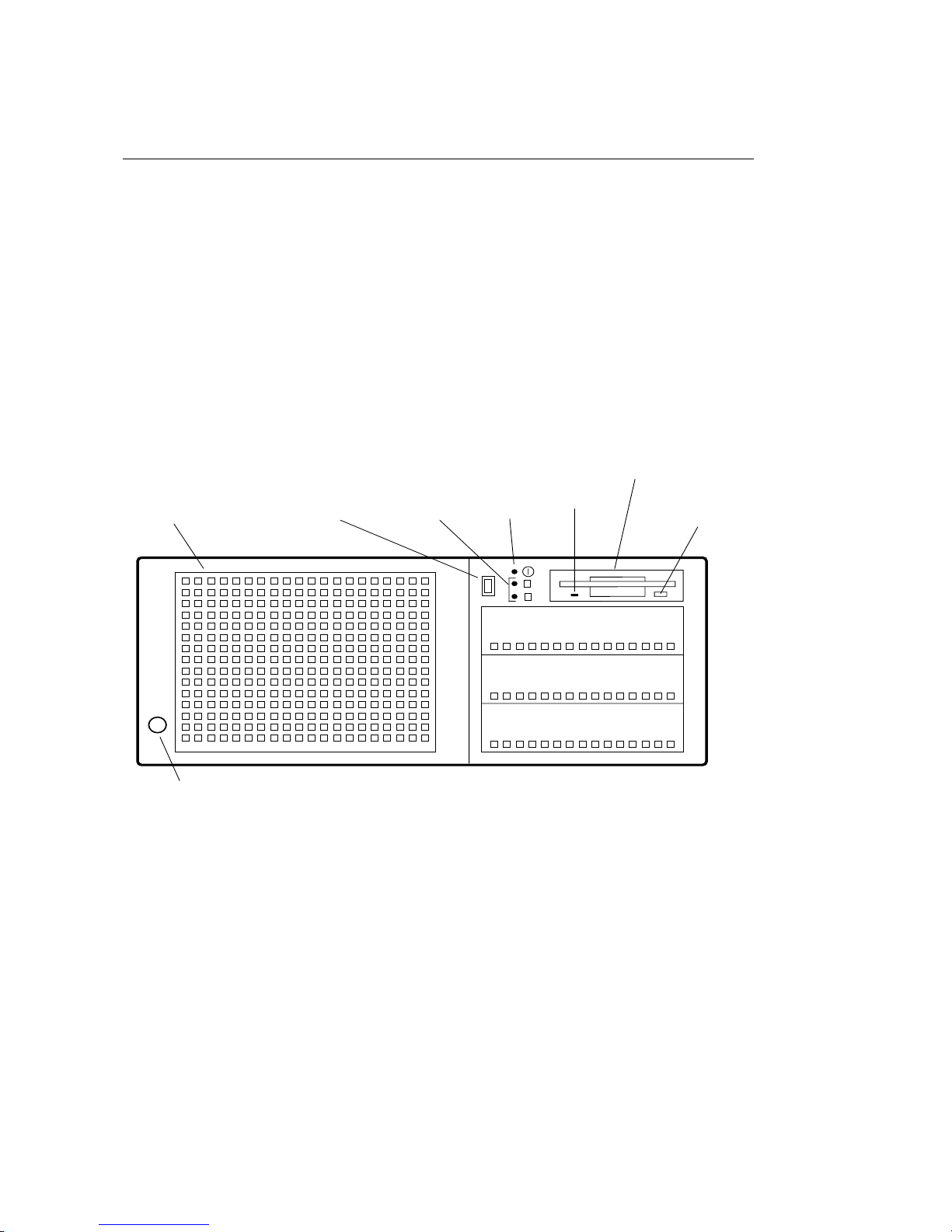
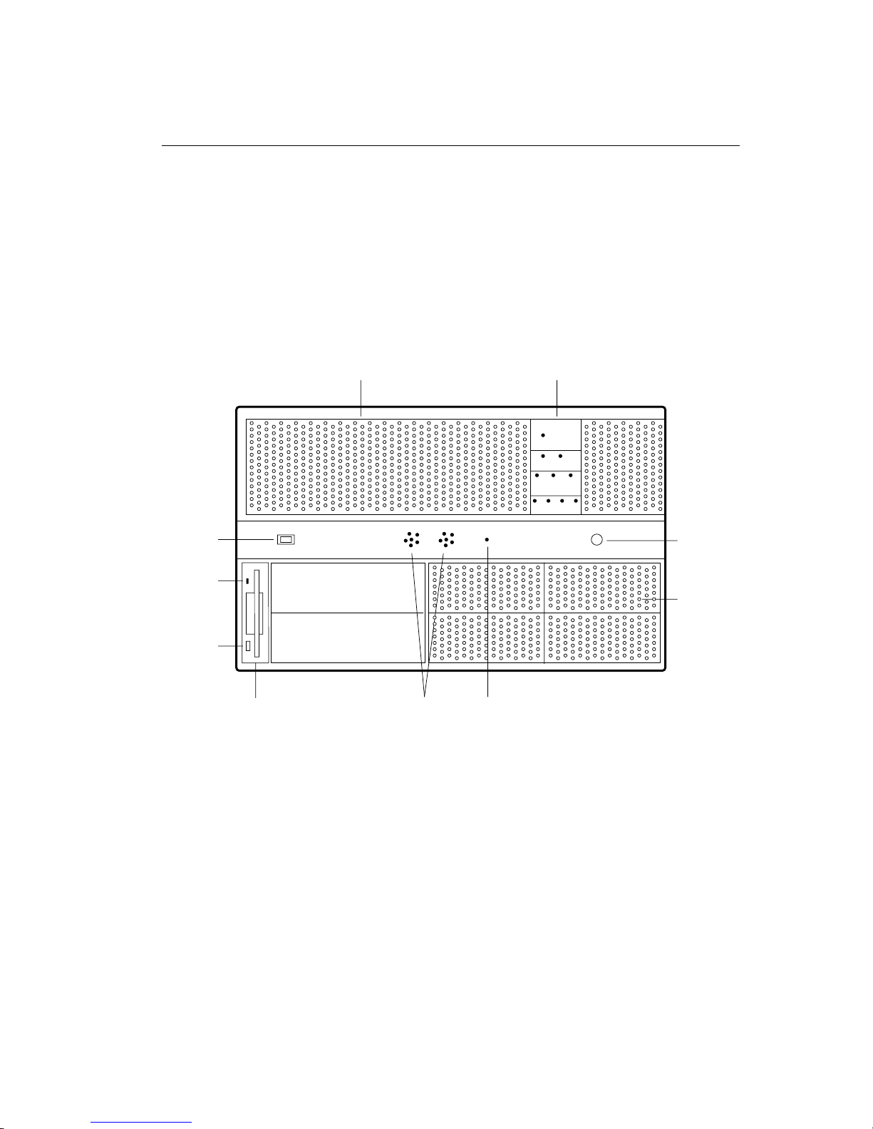
Familiarize yourself with the Freeway’s front panel. Figure 2–1 shows a front view of the
Freeway 1200 and Figure 2–2 shows a front view of the Freeway 1300. See Appendix B
for a description of the Freeway 1300 LED panel and alarm functions.
3.5-inch
floppy
drive
Air vents
Power
on/off
switch
Hard drive
LEDs
Power
LED
Floppy
drive light
1
2
Drive Bay
Floppy disk
eject
button
Drive Bay
Drive Bay
Unused
keyboard
connector
3577
Figure 2–1: Front View: Freeway 1200 (lockable door not shown)
34 DC 900-1537B
Page 35
System
power
on/off
switch
Floppy
drive light
Floppy disk
eject
button
Air vents
Drive Bay
Drive Bay
2: Hardware Installation
Temperature,
fan, voltage, and
drive LEDs
TEMP
FAN
1 2
VOLTAGE
+5 +12 3.3
DRIVE
1 2 3 4
Unused
keyboard
connector
Unused
SCA SCSI
drive bays
3584
3.5-inch
floppy
drive
Figure 2–2: Front View: Freeway 1300 (lockable door not shown)
DC 900-1537B 35
Alarm
speakers
Reset
button
(recessed)
Page 36
Freeway 1200/1300 Hardware Installation Guide
Scaled 80%
Drawings are
in Times New
Roman but it’s
close enough to
Minion for me!
Step 6:
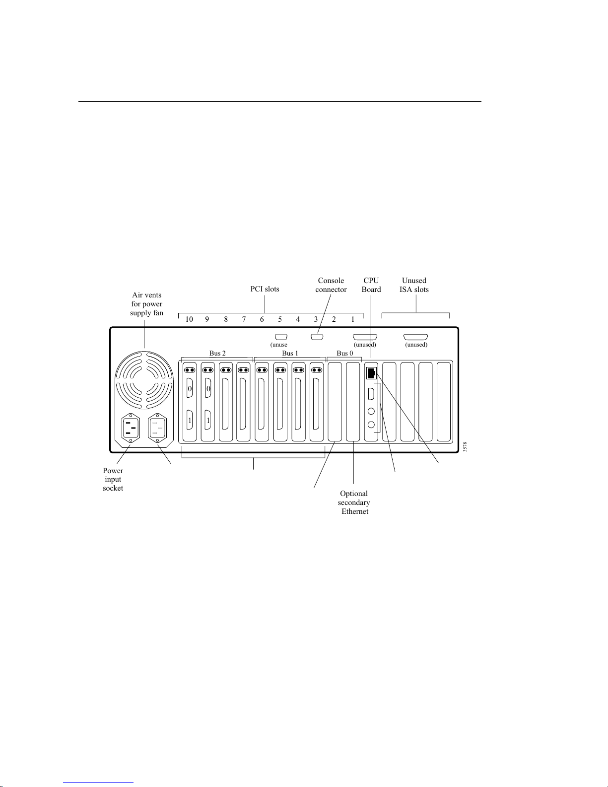
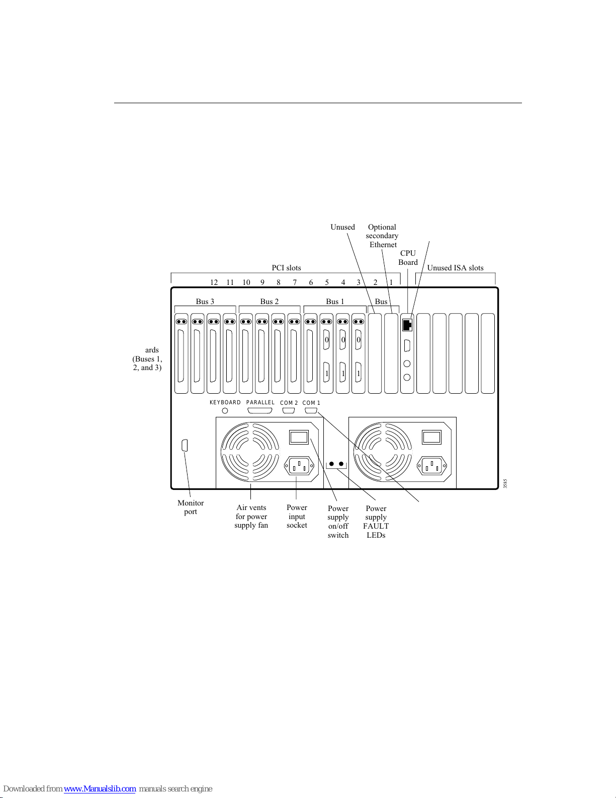
Familiarize yourself with the Freeway’s back panel. Figure 2–3 shows a Freeway 1200
and Figure 2–4 shows a Freeway 1300. Unused slots are covered by metal plates.
Unused
ISA slots
(unused)(unused)(unused)
Air vents
for power
supply fan
1 0 1
PCI slots
Bus 1Bus 2 Bus 0
0
Console
connector
CPU
Board
12345678910
3578
Power
input
socket
Accessory
AC
socket
ICP
Boards
Unused
Optional
secondary
Ethernet
Unused
connectors
Primary
Ethernet
Figure 2–3: Example Back View: Freeway 1200
36 DC 900-1537B
Page 37
2: Hardware Installation
ICP
Boards
(Buses 1,
2, and 3)
Unused
PCI slots
1314
Bus 3 Bus 1 Bus 0
Bus 2
0
1
1
KEYBOARD
Monitor
port
PARALLEL
Air vents
for power
supply fan
COM 2 COM 1
Power
input
socket
Power
supply
on/off
switch
Optional
secondary
Ethernet
010
Power
supply
FAULT
LEDs
CPU
Board
123456789101112
connector
Primary
Ethernet
Unused ISA slots
3585
Console
DC 900-1537B 37
Figure 2–4: Example Back View: Freeway 1300
Page 38

Freeway 1200/1300 Hardware Installation Guide
Step 7:
Make sure that the power switch on the front panel is off, then make the LAN connec-
tions. The Freeway’s CPU board has an RJ-45 connector for twisted-pair cable comply-
Save: Ethernet
is on CPU
board for a
3200/1300,
but is a
separate board
for the
3100/3150.
ing with the 10/100BaseT specification.
Caution
Alert your system administrator before making connections to
your LAN. To avoid a disruption of service on your LAN, carefully
plan how you will make the connections. We recommend that you
power off the Freeway server and modem during cable installation
and removal.
Check with your system administrator to find out what type of cable is used at your site.
You may need to use a mini-hub to convert from 10BaseT to 10Base2 or 10Base5.
(100BaseT always uses the RJ-45 connector.) You can obtain the necessary equipment
and cables from a computer accessory vendor.
38 DC 900-1537B
Page 39
2: Hardware Installation
Step 8:
Make sure that the power switch on the front panel is off, then connect the ICP boards
to your wide area network.
Caution
We recommend that you power off the Freeway server and modem
during cable installation and removal. This will prevent damage to
an ICP due to electrical discharge as contact is made or broken.
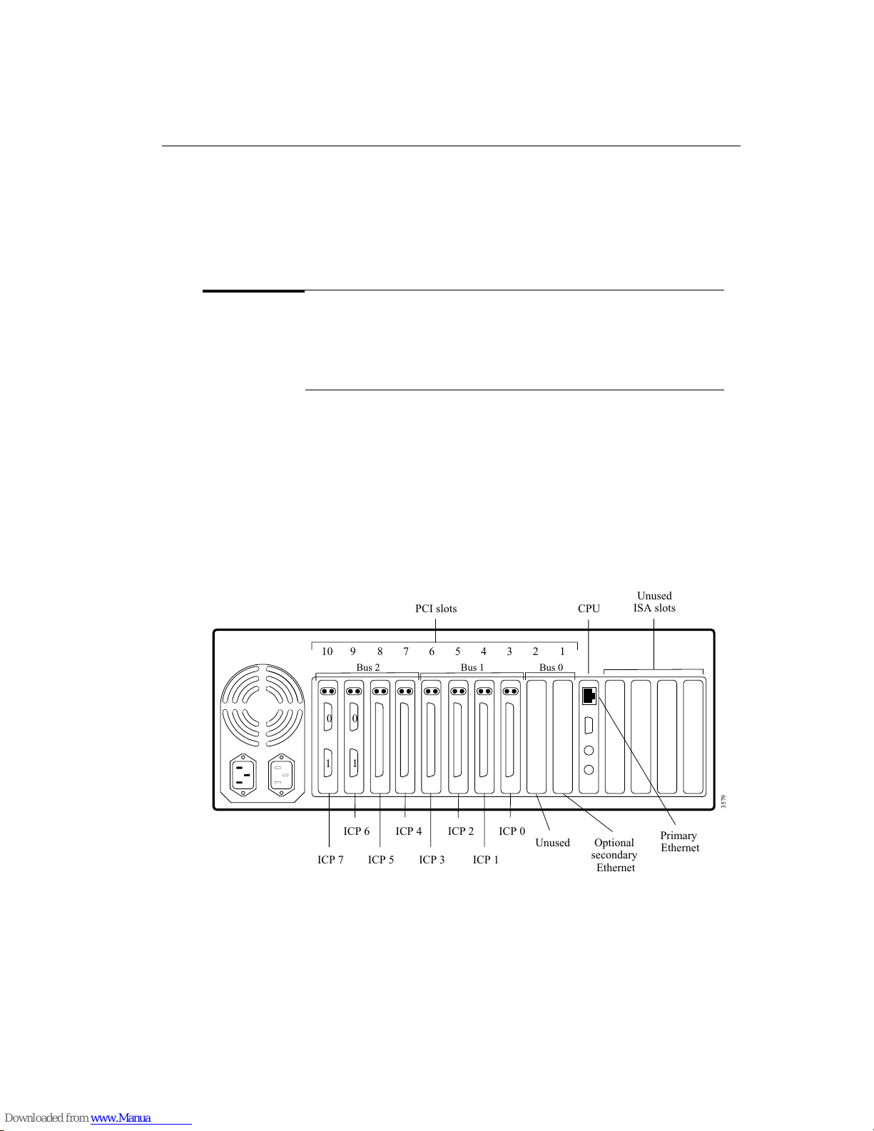
Figure 2–5 shows an example Freeway 1200 hardware configuration. The Freeway 1200
has ten PCI slots used by up to eight ICP2432 boards, an optional PCI interface board,
and an optional secondary Ethernet Network Interface Card (NIC); one CPU slot; and
four unused ISA slots. In this example, ICP 0 through ICP 5 are four-port or eight-port
boards and ICP 6 and ICP 7 are two-port boards.
Unused
PCI slots
CPU
ISA slots
Drawing is in
Times New
Roman but it’s
close enough to
Minion for me!
I have
separate
drawings here
to show ICP
numbering
rather than
just referring
back to the
original
drawings. It
would be hard
to show 1300
ICP
numbering
on top of all
the other
labels.
12345678910
Bus 1Bus 2 Bus 0
0
1 0 1
3579
ICP 0ICP 2ICP 4ICP 6
Unused
ICP 1ICP 3ICP 5ICP 7
Optional
secondary
Ethernet
Primary
Ethernet
Figure 2–5: ICP Numbering: Freeway 1200
DC 900-1537B 39
Page 40
Freeway 1200/1300 Hardware Installation Guide
Drawing is in
Times New
Roman but it’s
close enough to
Minion for me!
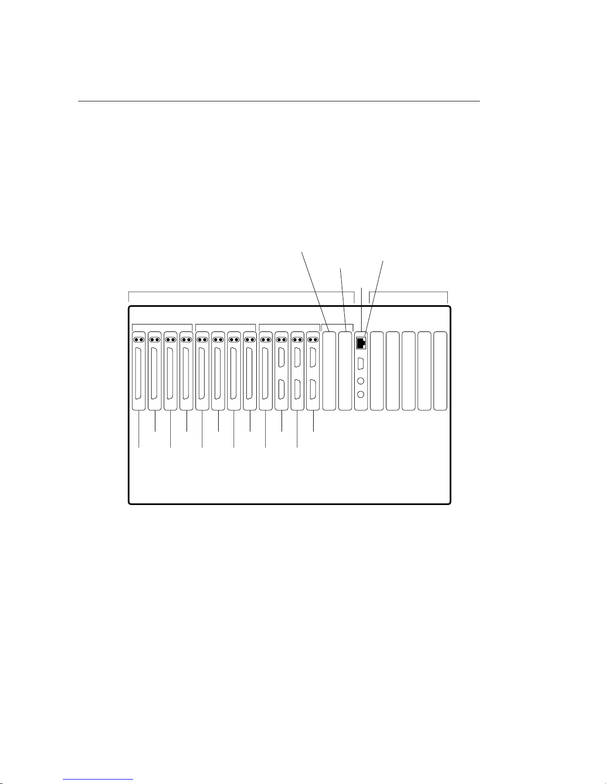
Figure 2–6 shows an example Freeway 1300 hardware configuration. The Freeway 1300
has fourteen PCI slots used by up to 12 ICP2432 boards, an optional PCI interface
board, and an optional secondary Ethernet Network Interface Card; one CPU slot; and
five unused ISA slots. In this example, ICP 0, ICP 1, and ICP 2 are two-port boards and
ICP 3 through ICP 11 are four-port or eight-port boards.
1
Optional
secondary
Ethernet
010
Primary
Ethernet
CPU
Unused ISA slots
123456789101112
Unused
PCI slots
1314
Bus 3 Bus 1 Bus 0
Bus 2
0
1
ICP 0ICP 2ICP 4ICP 6ICP 8ICP 10
ICP 1ICP 3ICP 5ICP 7ICP 9ICP 11
3586
Figure 2–6: ICP Numbering: Freeway 1300
40 DC 900-1537B
Page 41

2: Hardware Installation
The order of the PCI boards in the Freeway is arbitrary. The order shown in Figure 2–5
for the Freeway 1200 and Figure 2–6 for the Freeway 1300 matches the standard config-
uration shown in the boot configuration file, which is also the standard order of the
boards as installed by Simpact.
If your configuration has more than one ICP board, the boards are always numbered
from right to left when looking at the back of the Freeway. The two slots closest to the
CPU board are reserved for an optional second Ethernet board or other optional PCI
interface board. ICP 0 is the next board. The two-port board has two separate 26-pin
high-density connectors; port 0 is the top connector and port 1 is the bottom connec-
tor. Both the four-port and the eight-port boards have the same 100-pin high-density
connector. The four-port board uses a “quadrapus” (one-to-four) cable to attach four
DB25 or DB37 connectors to the 100-pin connector. The eight-port board uses an
“octopus” (one-to-eight) cable to attach eight DB25 connectors to the 100-pin connec-
tor. Port numbers are identified on the terminating ends of the quadrapus or octopus
cable.
Step 9:
Plug the power cord into the power input socket on the Freeway’s back panel and into
an AC electrical outlet near your Freeway.
Step 10:
Perform the software installation procedures on your boot server as described in the
Freeway User Guide.
Step 11:
Configure the boot parameters. There are two ways to do this. You can use the boot
parameter initialization disk as described in Chapter 3 or you can attach a local console
to your Freeway as described in Chapter 4.
DC 900-1537B 41
Page 42

Freeway 1200/1300 Hardware Installation Guide
42 DC 900-1537B
Page 43

Chapter
Configuring the Boot
3
Parameters using the
Initialization Disk
This chapter describes how to use the boot parameter initialization disk to configure the
boot parameters and boot the Freeway server. You can boot the Freeway from a boot
server attached to the local area network or from the Freeway’s hard or flash drive. If
you are booting from a boot server, it is assumed that:
1. You have performed the hardware installation procedures described in Chapter 2.
2. You know which protocol you will be installing on your boot server (for example,
BSC2780/3780, FMP, or X.25). The protocol is indicated on the label of the
software distribution media.
Note
If you are installing more than one protocol, it is best to perform
the software installation (described in the Freeway User Guide)
and loopback verification testing (described in the Freeway Loop-
back Test Procedures) for one protocol before attempting to customize your Freeway system for multiple protocols.
Item 2 is in
FW docs only;
you don’t even
have to edit
load files for
SR.
3. The system administrator has set up a file transfer protocol (FTP) or remote shell
(RSH) user name and password on the boot server to match the FTP user name
and the FTP password in the Freeway system boot parameters. The default FTP
user name is
DC 900-1537B 43
ffffrrrreeeeeeeewwwwaaaayy
yy
and the default FTP password is pp
ppaaaasssssssswwwwoooorrrrdddd
.
Page 44

Freeway 1200/1300 Hardware Installation Guide
You can change the default FTP user name and FTP password that the Freeway
uses by changing the corresponding boot parameters on the Freeway system. If
you do, remember that you must also change the user name and password of the
FTP account on the boot server.
4. The system administrator has assigned the following device names and addresses
Because this is
the
installation
manual, Eric
had me take
out most (or
all) of the
references to
the local disk.
We’ll rewrite
this when the
SmartServer
is finished. See
1675 (Air
Force training
manual) for
the deleted
entries -search on disk.
in the UNIX
/etc/hosts file, the Windows NT hosts or lmhosts file, or using
your VMS TCP/IP package:
• Freeway server name and Internet address
• Boot server name and Internet address
• Gateway Internet address (if applicable)
The procedure for configuring the boot parameters is the same for UNIX, VMS, and
Windows NT systems. Freeway obtains the boot parameters from local non-volatile
memory during system boot. Therefore, when you configure the boot parameters in the
following steps, all applicable parameters must be configured.
Step 1:
The boot parameter initialization disk is a DOS-formatted floppy disk. Insert it in any
PC. The
this file to configure the boot parameters as described in Table 3–1. Be sure to select the
appropriate option to save this file as text if this is not the default format of your editor.
bootparm.txt file, shown in Figure 3–1, can be viewed with any text editor. Edit
44 DC 900-1537B
Page 45

3: Configuring the Boot Parameters using the Initialization Disk
Boot_Device : fei
Processor_Number : 0
FTP_User_Name : freeway
FTP_Password : password
Flags : 0
Freeway_Server_Name : freeway1
Freeway_Inet_Address : 207.67.135.224
Freeway_Subnet_Mask : ffffff00
Boot_Server_Name : bootmaster
Boot_Server_Inet_Address : 207.67.135.198
System_Boot_Directory : /usr/local/freeway/boot
System_Boot_File_Name : fw486
Configuration_File_Name : bootcfg.pci
Secondary_Net_Interface :
Gateway_Inet_Address :
Figure 3–1: Example of the Freeway System Boot Parameters
Table 3–1: Freeway System Boot Parameters
Boot Parameter Description
Boot Device
Processor Number The only valid number for this parameter is 0.
To boot over Fast Ethernet from the boot server using the primary
Ethernet (on the CPU board), set the boot device to ff
To boot over Fast Ethernet from the boot server using the secondary
Ethernet board, set the boot device to ff
ffeeeeiiii1111
To boot from the local disk, set the boot device to ii
For Freeway,
you always see
password. It’s
only for SR
with a local
console that I
use ### to
indicate that
password isn’t
seen.
11-03-99: Per
Ron Tabor,
Primary
Network
Interface is for
SmartRouter
ffeeeeiiii
or ff
ffeeeeiiii0000
.
only at this
time.
.
iiddddeeee====0000,,,,0000....
FTP User Name If booting from the boot server, Freeway uses this name to log in to its
FTP Password If booting from the boot server, Freeway uses this password to log in to
DC 900-1537B 45
FTP (or RSH) user account. The default is ff
ffrrrreeeeeeeewwwwaaaayyyy
. This is not required
if you are booting from the local disk.
its user account. The default is pp
ppaaaasssssssswwwwoooorrrrdddd
. This parameter is optional. If
a password is given, FTP is used during system boot; if it is cleared, the
remote shell (RSH) protocol is used.
Page 46

Freeway 1200/1300 Hardware Installation Guide
Table 3–1: Freeway System Boot Parameters (Cont’d)
Boot Parameter Description
Flags
This parameter specifies whether you want Freeway to:
• Autoboot two seconds after system reset, seven seconds after
system reset, or not at all
• Display the version numbers of the .mem files
• Force the primary boot network interface to operate at 10
megabits/second, half duplex
Enter the Flags value shown in Table 3–2 on page 47 that matches your
configuration requirements. The default Flags value is 0. The Flags
word is an inclusive “OR” of the desired bits for the individual functions.
Freeway Server Name Enter the system name assigned by the system administrator for this
Freeway.
Freeway Inet Address Enter the Internet address assigned by the system administrator for
this Freeway in decimal dot notation (for example, 207.67.135.84).
Freeway Subnet Mask If your Freeway is located on a subnet, enter the subnet mask in hexa-
decimal notation (for example, ffffff00).
Boot Server Name Enter the name assigned by the system administrator for the boot
server. Optionally, you can clear this field and the software will assign
the default name “bootserver.” If you are booting from the local disk,
this parameter is ignored.
Boot Server Inet Address Enter the Internet address assigned by the system administrator for the
boot server in decimal dot notation (for example, 207.67.135.84). If
you are booting from the local disk, this parameter is ignored
System Boot Directory If the Freeway boot files will be stored in the home directory of the FTP
(or RSH) user account, clear this field. Otherwise, enter the full path
name of the boot directory. The default UNIX directory is
/usr/local/freeway/boot. The default VMS directory is
SYS$SYSDEVICE:[FREEWAY.BOOT]. For Windows NT versions earlier
than 4.0, the default directory is c:\freeway\boot. For Windows NT
4.0 or later, use the alias you have set up to point to the
directory.
To boot from the local disk, set the system boot directory to //
System Boot File Name Enter the system boot file name for this Freeway. The default is ff
46 DC 900-1537B
freeway\boot
//iiiiddddeeee
.
ffwwww444488886666
.
Page 47

3: Configuring the Boot Parameters using the Initialization Disk
Table 3–1: Freeway System Boot Parameters (Cont’d)
Boot Parameter Description
Configuration File Name This parameter contains the file that Freeway uses to configure the
physical devices and services. Enter the file name for your Freeway. The
default is bb
devices, the default is
bboooooooottttccccffffgggg....ppppcccciiii
. For any Freeway using ICP_IP virtual ICP
bbbboooooooottttccccffffgggg....iiiipppp....
Secondary Network
Interface
If the Boot Device is a local area network device (boot server), the
Secondary Network Interface parameter should be cleared, which is
the default.
If the Boot Device is the hard or flash disk, this parameter specifies the
local area network device to be used after Freeway boots. Set this
parameter to ff
ffeeeeiiii1111
or ff
ffeeeeiiii
to use the primary Fast Ethernet (on the CPU board)
to use the secondary Fast Ethernet board.
Gateway Inet Interface If your Freeway and boot server are on the same network, clear this
parameter, which is the default. If they are on different networks, enter
the IP address of the gateway processor on the Freeway’s network that
provides access to the boot server’s network.
Table 3–2: Flags for Reset Action
Flags Parameter Value Boot Protocol and Reset Action
0x0000 (default) Upon system reset, wait 7 seconds before autobooting.
0x0004 Upon system reset, display the Freeway Boot System Main Menu.
Do not autoboot.
0x0008 Upon system reset, wait 2 seconds before autobooting.
0x1000 Display version numbers of .mem files downloaded to an ICP
0x2000
DC 900-1537B 47
during boot. The Flags word is an inclusive “OR” of the desired bits
for the individual functions; for example, 0x1008 waits 2 seconds
before autobooting and displays the version numbers.
Force primary boot network interface to operate at 10 megabits/
second, half duplex. The Flags word is an inclusive “OR” of the
desired bits for the individual functions; for example, 0x2008 waits
2 seconds before autobooting and forces the 10 megabits/second
speed.
11-03-99: Per
Ron Tabor,
0x2000 is for
Freewqy only
at this time.
Page 48

Freeway 1200/1300 Hardware Installation Guide
Step 2:
Use the blank form in Figure 3–2 to write down your boot parameter configurations for
future reference.
Freeway System Boot Parameters
------------------------------
Boot Device : _____________________________________
Processor Number : _____________________________________
FTP User Name : _____________________________________
FTP Password : _____________________________________
Flags : _____________________________________
Freeway Server Name : _____________________________________
Freeway Inet Address : _____________________________________
Freeway Subnet Mask : _____________________________________
Boot Server Name : _____________________________________
Boot Server Inet Address : _____________________________________
System Boot Directory : _____________________________________
System Boot File Name : _____________________________________
Configuration File Name : _____________________________________
Secondary Net Interface : _____________________________________
Gateway Inet Address : _____________________________________
Figure 3–2: Configured Freeway System Boot Parameters
48 DC 900-1537B
Page 49

3: Configuring the Boot Parameters using the Initialization Disk
Step 3:
Save the file to the floppy disk, then remove the floppy disk from the PC.
Step 4:
Insert the initialization disk in the Freeway’s floppy drive. Turn on the power. The boot
parameters you configured in the
bootparm.txt file are copied to local non-volatile
memory.
If the boot parameters were entered correctly, the following message is printed to the
copylog.txt file on the disk and the Freeway boots:
Boot parameters copied from floppy disk successfully.
The boot image performs rudimentary error checking on some of the parameters to
verify that the values provided are of the correct format for the parameter type, but
otherwise simply writes the parameters into the
error checking detects a problem, a message is printed to the
NVRAM.txt file exactly as provided. If
copylog.txt file, but
Freeway repeatedly attempts to boot, reading the parameters from the floppy disk and
failing until it is powered off. If an undetected error occurs (for example, a critical
parameter missing or misspelled in the
cessful copying of the parameters to the disk will be printed to the
bootparm.txt file), a message indicating suc-
copylog.txt file, but
Freeway will continue to boot without success.
If Freeway attempts to boot for several minutes (as can be detected by its beeping and
accessing the floppy drive), assume that there is a problem with the boot parameters or
the network connection. Turn off the Freeway server and remove the floppy disk. Insert
the boot parameter initialization disk in the PC again and review the boot parameters
on the disk to be sure they are set correctly for your Freeway’s configuration.
DC 900-1537B 49
Page 50

Freeway 1200/1300 Hardware Installation Guide
Step 5:
After Freeway boots successfully, remove the initialization disk from the floppy drive.
Note
After the initial system boot, you can telnet or rlogin to Freeway
from the boot server (or from any other computer on the network)
and use the Freeway Interactive Menu for Freeway operations as
described in the Freeway User Guide.
You can use the Freeway Interactive Menu to modify the boot parameters. If, however,
Freeway is booted with the boot parameter initialization disk in the floppy drive, any
boot parameters that were modified using the Freeway menu will be overwritten by the
values in the
bootparm.txt file on the initialization disk.
Step 6:
Run the loopback test to check the hardware and software installation as described in
the Freeway Loopback Test Procedures.
Step 7:
If Freeway will normally boot from the boot server, installation is complete. If Freeway
will boot from its local disk, you must download the files from the boot server onto the
local disk. Follow the instructions in the Build Hard Disk from Boot Server section in
the Freeway User Guide.
50 DC 900-1537B
Page 51

Chapter
Configuring the Boot
4
Parameters using the
Local Console
This chapter describes how to use the local console to configure the boot parameters
and boot Freeway. You can boot Freeway from a boot server attached to the local area
network or from Freeway’s hard or flash drive. If you are booting from a boot server, it
is assumed that:
1. You have performed the hardware installation procedures described in Chapter 2.
2. You know which protocol you will be installing on your boot server (for example,
BSC2780/3780, FMP, or X.25). The protocol is indicated on the label of the
software distribution media.
Note
If you are installing more than one protocol, it is best to perform
the software installation (described in the Freeway User Guide)
and loopback verification testing (described in the Freeway Loop-
back Test Procedures) for one protocol before attempting to customize your Freeway system for multiple protocols.
Item 2 is in
FW docs only;
you don’t even
have to edit
load files for
SR.
3. The system administrator has set up a file transfer protocol (FTP) or remote shell
(RSH) user name and password on the boot server to match the FTP user name
and the FTP password in the Freeway system boot parameters. The default FTP
user name is
DC 900-1537B 51
ffffrrrreeeeeeeewwwwaaaayy
yy
and the default FTP password is pp
ppaaaasssssssswwwwoooorrrrdddd
.
Page 52

Freeway 1200/1300 Hardware Installation Guide
You can change the default FTP user name and FTP password that Freeway uses
by changing the corresponding boot parameters on the Freeway. If you do,
remember that you must also change the user name and password of the FTP
account on the boot server.
4. The system administrator has assigned the following device names and addresses
in the UNIX
your VMS TCP/IP package:
/etc/hosts file, the Windows NT hosts or lmhosts file, or using
• Freeway name and Internet address
• Boot server name and Internet address
• Gateway Internet address (if applicable)
The procedure for configuring the Freeway system boot parameters is the same for
UNIX, VMS, and Windows NT systems. Freeway obtains the boot parameters from
local non-volatile memory during system boot. Therefore, when you configure the boot
parameters in the following steps, all applicable parameters must be configured.
Step 1:
Connect a VT100-compatible terminal or terminal emulator to Freeway using the cable
supplied with your Freeway that has both a 9-pin and a 25-pin connector at each end.
Connect the 9-pin connector on one end of the cable to the console connector on the
Freeway’s back panel. For the location of this connector, see Figure 2–3 on page 36 for
the Freeway 1200 or Figure 2–4 on page 37 for the Freeway 1300. Connect the 25-pin
connector on the other end of the cable to the VT100-compatible terminal or emulator
that you want to use as a console.
You will use this terminal or emulator as a console to configure the boot parameters and
perform the initial system boot. Later you can disconnect the terminal or emulator
because you can then perform these configuration functions using telnet or rlogin
through any terminal or workstation connected to the network.
52 DC 900-1537B
Page 53

4: Configuring the Boot Parameters using the Local Console
Step 2:
Configure the console terminal to operate with the following communications param-
eters:
• 9600 bits per second
• 8 bits data
• 1 stop bit
• No parity
• xon/xoff enabled
Step 3:
Turn the power switch on the front panel on.
Step 4:
When prompted on the console screen, press <return> within 7 seconds to prevent the
autoboot attempt. The Freeway Boot System Main Menu shown in Figure 4–1 appears.
Note
The Freeway Boot System Main Menu is only accessible using the
local console connected to the rear of the Freeway unit. Later you
can access these same functions from any remote console using the
Freeway Interactive Menu as described in the Freeway User
Guide.
DC 900-1537B 53
Page 54

Freeway 1200/1300 Hardware Installation Guide
Freeway Boot System Main Menu
-----------------------------
1) System Boot
2) Display Boot Parameters
3) Edit Boot Parameters
Select:
Figure 4–1: Freeway Boot System Main Menu
54 DC 900-1537B
Page 55

4: Configuring the Boot Parameters using the Local Console
Step 5:
Select option 3 to edit the boot parameters. The system displays the parameters one at
a time. Three actions are possible as each parameter is displayed:
• To preserve a parameter, press <return>
• To edit a parameter, type the new alpha-numeric information and press <return>
• To clear a parameter, press the period key (‘.’) followed by <return>
Figure 4–2 shows an example of a Freeway System Boot Parameters screen.
Freeway System Boot Parameters
----------------–––----------Boot Device : fei
Processor Number : 0
FTP User Name : freeway
FTP Password : password
Flags : 0
Freeway Server Name : freeway1
Freeway Inet Address : 207.67.135.224
Freeway Subnet Mask : ffffff00
Boot Server Name : bootmaster
Boot Server Inet Address : 207.67.135.198
System Boot Directory : /usr/local/freeway/boot
System Boot File Name : fw486
Configuration File Name : bootcfg.pci
Secondary Net Interface :
Gateway Inet Address :
For Freeway,
you always see
password. It’s
only for SR
with a local
console that I
use ### to
indicate that
password isn’t
seen.
Figure 4–2: Example of the Freeway System Boot Parameters
DC 900-1537B 55
Page 56

Freeway 1200/1300 Hardware Installation Guide
Step 6:
Configure the boot parameters as described in Table 4–1.
Table 4–1: Freeway System Boot Parameters
Boot Parameter Description
Boot Device To boot over Fast Ethernet from the boot server using the primary
ffeeeeiiii
Ethernet (on the CPU board), set the boot device to ff
To boot over Fast Ethernet from the boot server using the secondary
ppaaaasssssssswwwwoooorrrrdddd
ffeeeeiiii1111
.
iiddddeeee====0000,,,,0000
ffrrrreeeeeeeewwwwaaaayyyy
. This parameter is optional. If
. This is not required
Ethernet board, set the boot device to ff
To boot from the local disk, set the boot device to ii
Processor Number The only valid number for this parameter is 0.
FTP User Name If booting from the boot server, Freeway uses this name to log in to its
FTP (or RSH) user account. The default is ff
if you are booting from the local disk.
FTP Password If booting from the boot server, Freeway uses this password to log in to
its user account. The default is pp
a password is given, FTP is used during system boot; if it is cleared, the
remote shell (RSH) protocol is used.
Flags
This parameter specifies whether you want Freeway to:
or ff
.
ffeeeeiiii0000
.
• Autoboot two seconds after system reset, seven seconds after
system reset, or not at all
• Display the version numbers of the .mem files
• Force the primary boot network interface to operate at 10
megabits/second, half duplex
Enter the Flags value shown in Table 4–2 on page 58 that matches your
configuration requirements. The default Flags value is 0. The Flags
word is an inclusive “OR” of the desired bits for the individual functions.
Freeway Server Name Enter the system name assigned by the system administrator for this
Freeway.
Freeway Inet Address Enter the Internet address assigned by the system administrator for
this Freeway in decimal dot notation (for example, 207.67.135.84).
Freeway Subnet Mask If your Freeway is located on a subnet, enter the subnet mask in hexa-
decimal notation (for example, ffffff00).
56 DC 900-1537B
Page 57

4: Configuring the Boot Parameters using the Local Console
Table 4–1: Freeway System Boot Parameters (Cont’d)
Boot Parameter Description
Boot Server Name Enter the name assigned by the system administrator for the boot
server. Optionally, you can clear this field and the software will assign
the default name “bootserver.” If you are booting from the local disk,
this parameter is ignored.
Boot Server Inet Address Enter the Internet address assigned by the system administrator for the
boot server in decimal dot notation (for example, 207.67.135.84). If
you are booting from the local disk, this parameter is ignored.
System Boot Directory
System Boot File Name Enter the system boot file name for this Freeway. The default is ff
If the Freeway boot files will be stored in the home directory of the FTP
(or RSH) user account, clear this field. Otherwise, enter the full path
name of the boot directory. The default UNIX directory is
/usr/local/freeway/boot. The default VMS directory is
SYS$SYSDEVICE:[FREEWAY.BOOT]. For Windows NT versions earlier
than 4.0, the default directory is c:\freeway\boot. For Windows NT
4.0 or later, use the alias you have set up to point to the freeway\boot
directory.
To boot from the local disk, set the system boot directory to //
//iiiiddddeeee
.
ffwwww444488886666
.
Configuration File Name This parameter contains the file that Freeway uses to configure the
physical devices and services. Enter the file name for your Freeway. The
bboooooooottttccccffffgggg....ppppcccciiii
. For any Freeway using ICP_IP virtual ICP
bbbboooooooottttccccffffgggg....iiiipppp....
Secondary Network
Interface
default is bb
devices, the default is
If the Boot Device is a local area network device (boot server), the
Secondary Network Interface parameter should be cleared, which is
the default.
If the Boot Device is the hard or flash disk, this parameter specifies the
local area network device to be used after the Freeway boots. Set this
parameter to ff
ffeeeeiiii1111
or ff
ffeeeeiiii
to use the primary Fast Ethernet (on the CPU board)
to use the secondary Fast Ethernet board.
Gateway Inet Interface If your Freeway and boot server are on the same network, clear this
parameter, which is the default. If they are on different networks, enter
the IP address of the gateway processor on the Freeway’s network that
provides access to the boot server’s network.
DC 900-1537B 57
Page 58

Freeway 1200/1300 Hardware Installation Guide
Table 4–2: Flags for Reset Action
Flags Parameter Value Boot Protocol and Reset Action
0x0000 (default) Upon system reset, wait 7 seconds before autobooting.
0x0004 Upon system reset, display the Freeway Boot System Main Menu.
Do not autoboot.
0x0008 Upon system reset, wait 2 seconds before autobooting.
11-03-99: Per
Ron Tabor,
0x2000 is for
Freeway only
at this time.
0x1000 Display version numbers of .mem files downloaded to an ICP
during boot. The Flags word is an inclusive “OR” of the desired bits
for the individual functions; for example, 0x1008 waits 2 seconds
before autobooting and displays the version numbers.
0x2000
Force primary boot network interface to operate at 10 megabits/
second, half duplex. The Flags word is an inclusive “OR” of the
desired bits for the individual functions; for example, 0x2008 waits
2 seconds before autobooting and forces the 10 megabits/second
speed.
Step 7:
After you have entered the last parameter (
Save modifications?
Enter 'yes <return>' to save modifications.
Enter 'no <return>' to prevent modifications.
If all of the parameters have been entered correctly, enter yy
ss
yyyyeeeess
If you enter
, the screen displays the following message, and the system returns to the
Gateway Inet Interface), the screen displays:
yyeeeessss
; otherwise, enter nn
Freeway Boot System Main Menu after data storage completes:
nnoooo
.
<<< Storing Data to IDE Disk >>>
oo
nnnnoo
If you enter
, the system returns to the Freeway Boot System Main Menu with no
modifications to the boot parameters.
58 DC 900-1537B
Page 59

4: Configuring the Boot Parameters using the Local Console
Step 8:
Select option 2 at the Freeway Boot System Main Menu (Figure 4–1 on page 54) to
review the current boot parameters. Verify that the changes you entered are correct. If
the changes are incorrect, or you entered
oo
nnnnoo
to store data, select option 3 again and
modify the boot parameters to their correct values.
Step 9:
Select option 1 from the Freeway Boot System Main Menu (Figure 4–1 on page 54) on
the Freeway console to perform the system boot.
Note
After the initial system boot, you can telnet or rlogin to Freeway
from the boot server (or from any other computer on the network)
and use the Freeway Interactive Menu for Freeway operations as
described in the Freeway User Guide.
Step 10:
Use the blank form in Figure 4–3 to write down your boot parameter configurations for
future reference.
Step 11:
Run the loopback test to check the hardware and software installation as described in
the Freeway Loopback Test Procedures.
Step 12:
If Freeway will normally boot from the boot server, installation is complete. If Freeway
will boot from its local disk, you must download the files from the boot server onto the
local disk. Follow the instructions in the Build Hard Disk from Boot Server section in
the Freeway User Guide.
DC 900-1537B 59
Page 60

Freeway 1200/1300 Hardware Installation Guide
Freeway System Boot Parameters
------------------------------
Boot Device : _____________________________________
Processor Number : _____________________________________
FTP User Name : _____________________________________
FTP Password : _____________________________________
Flags : _____________________________________
Freeway Server Name : _____________________________________
Freeway Inet Address : _____________________________________
Freeway Subnet Mask : _____________________________________
Boot Server Name : _____________________________________
Boot Server Inet Address : _____________________________________
System Boot Directory : _____________________________________
System Boot File Name : _____________________________________
Configuration File Name : _____________________________________
Secondary Net Interface : _____________________________________
Gateway Inet Address : _____________________________________
Figure 4–3: Configured Freeway Boot Parameters
60 DC 900-1537B
Page 61

Appendix
A
Electrical Interfaces
Table A–1 shows the commonly used electrical interfaces for WAN connections. Each link in
a 2-port or 4-port ICP can be individually configured to EIA-232, EIA-449, EIA-530, or V.35.
The 8-port ICP provides EIA-232 only. If you select another value for an 8-port board, it will
be ignored.
Note
The Freeway is always Data Terminal Equipment (DTE), while
modems are Data Communications Equipment (DCE).
Table A–1: Commonly Used Electrical Interfaces
EIA-232 EIA-530 EIA-449 V.35
Signal Name Source
Shield – –1–1–1–A
Transmitted Data DTE BA 2 BA (A) 2 SD (A) 4 103 P
Received Data DCE BB 3 BB (A) 3 RD (A) 6 104 R
Request to Send DTE CA 4 CA (A) 4 RS (A) 7 105 C
Clear to Send DCE CB 5 CB (A) 5 CS (A) 9 106 D
DCE Ready (DSR) DCE CC 6 CC (A) 6 DM (A) 11 107 E
Mnemonic Pin Mnemonic Pin Mnemonic Pin Mnemonic Pin
BA (B) 14 SD (B) 22 103 S
BB (B) 16 RD (B) 24 104 T
CA (B) 19 RS (B) 25
CB (B) 13 CS (B) 27
CC (B) 22 DM (B) 29
All these are
the same:
3100/3150,
3200/7200,
1100/1150,
1200/1300
DC 900-1537B 61
Page 62

Freeway 1200/1300 Hardware Installation Guide
Table A–1: Commonly Used Electrical Interfaces (Cont’d)
EIA-232 EIA-530 EIA-449 V.35
Signal Name Source
DTE Ready (DTR) DTE CD 20 CD (A) 20 TR (A) 12 108 H
Signal Ground – AB 7 AB 7 SG 19 102 B
Receive Line Signal
Detect (DCD)
Transmit Signal
Element Timing
Receive Signal
Element Timing
Local Loopback DTE LL 18 LL 18 LL 10 141 L
Remote Loopback DTE RL 21 RL 21 RL 14 140 N
Ring Indicator DCE CD 22 ––––125J
Transmit Signal
Element Timing
Test Mode DCE RM 25 TM 25 TM 18 142 NN
DCE CF 8 CF (A) 8 RR (A) 13 109 F
DCE DB 15 DB (A) 15 ST (A) 5 114 Y
DCE DD 17 DD (A) 17 RT (A) 8 115 V
DTE DA 24 DA (A) 24 TT (A) 17 113 U
Mnemonic Pin Mnemonic Pin Mnemonic Pin Mnemonic Pin
CD (B) 23 TR (B) 30
CF (B) 10 RR (B) 31
DB (B) 12 ST (B) 23 114 AA
DD (B) 9 RT (B) 26 115 X
DA (B) 11 TT (B) 35 113 W
62 DC 900-1537B
Page 63
Appendix
Freeway 1300 LED Panel and
B
Alarm Functions
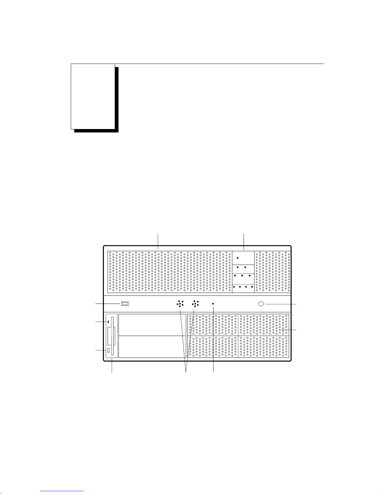
The front panel of the Freeway 1300, shown in Figure B–1, includes an LED panel to
indicate the status of various system functions such as temperature, fan status,
backplane voltage, and hard drive activity. These functions are described on the next
page.
Temperature,
fan, voltage, and
drive LEDs
TEMP
FAN
1 2
VOLTAGE
+5 +12 3.3
DRIVE
1 2 3 4
3584
System
power
on/off
switch
Floppy
drive light
Floppy disk
eject
button
Air vents
Drive Bay
Drive Bay
Unused
keyboard
connector
Unused
SCA SCSI
drive bays
3.5-inch
floppy
drive
Figure B–1: Front Panel: Freeway 1300 (lockable door not shown)
DC 900-1537B 63
Alarm
speakers
Reset
button
(recessed)
Page 64

Freeway 1200/1300 Hardware Installation Guide
Temperature LED This LED shows the status of the interior chassis environment
temperature. The valid settings are 35° C, 45° C, 55° C, and
65° C. The default temperature set at the factory is 45° C. A
solid green LED indicates that the temperature is equal to or
less than the selected value. A blinking red LED indicates a fault
condition; that is, the temperature is greater than the selected
value. The audible alarm is activated when the LED is blinking
red during a fault condition.
Chassis Fan
Status LEDs
These LEDs show the status of the chassis fans. FAN LED 1
monitors the fans in the front panel fan tray. Fan LED 2 moni-
tors the fan mounted below the ISA/PCI backplane and to the
rear of the SCA backplane. A solid green LED indicates that all
fan motors are rotating. A blinking red LED indicates a fault
condition. The audible alarm is activated when the LED is
blinking red during a fault condition.
Power Supply
Voltages LEDs
These LEDs show the status of the power supply voltages. The
+5, +12, and +3.3 volt DC outputs from the power supplies are
monitored. Nominal conditions are +/- 5% for the +5 and +3.3
volt supplies and +/- 10% for the +12 volt supply. A solid green
LED indicates a nominal condition. A red LED indicates a fault
condition. The audible alarm is activated when the LED is red
during a fault condition.
Drive LEDs These LEDs show the status of the hard drives. A green LED
64 DC 900-1537B
indicates drive access for read or write activity. A dark LED
indicates no activity or no drive installed.
Page 65

B: Freeway 1300 LED Panel and Alarm Functions
When an audible alarm is heard, check the LED indicator panel to determine the source
of the fault condition. If the fault condition is a fan, temperature, or voltage out of tol-
erance condition, you should schedule a maintenance shutdown as appropriate to cor-
rect the fault.
If all indicators on the LED panel are green and the alarm is sounding, one of the power
supplies is defective. The red LED that is illuminated on the rear of the Freeway indi-
cates which of the two power supplies must be replaced. Appendix C describes how to
replace a power supply.
DC 900-1537B 65
Page 66

Freeway 1200/1300 Hardware Installation Guide
66 DC 900-1537B
Page 67

Appendix
Replacing the Power Supply
C
The Freeway 1300 has optional dual independent hot-swappable power supplies with
separate AC feeds, designed to be easily replaced in the field. An audible alarm indicates
a power supply failure. The red power supply FAULT LED illuminated on the rear of the
Freeway shows which supply has failed (see Figure 2–4 on page 37).
To replace one of the power supplies while the system remains up, use the following
procedure:
1. Slip the anti-static strap around your wrist and attach the alligator clip to any bare
metal area of the Freeway cabinet.
2. On the power supply to be replaced, turn the power switch off, then unplug the
power cord.
in a Freeway 1300
3. Loosen the four Phillips screws in the outer corners of the power supply, then
remove the power supply completely from the cabinet.
Note
Do not pull the power supply part way out, then reinsert it.
Doing so may damage the power supply because the stored energy
will not have had time to dissipate completely.
DC 900-1537B 67
Page 68

Freeway 1200/1300 Hardware Installation Guide
4. Make sure the power switch on the new power supply is turned off, then push the
power supply firmly into place to ensure that all of the contacts at the rear of the
supply are properly inserted without any momentary makes and breaks which
could cause it to fail.
5. Tighten the screws to hold the new power supply in place.
6. Plug in the power cord, then turn the power switch on the power supply on.
If both power supplies are to be replaced, or if the system can be shut down to replace
one power supply, use the following procedure:
1. Inform all users that you will be shutting down the Freeway and they should stop
any devices that are currently sending messages to it.
2. After the client applications have terminated, select the ‘Logout’ option in the
Interactive Menu.
3. Slip the anti-static strap around your wrist and attach the alligator clip to any bare
metal area of the Freeway cabinet.
4. Power down the Freeway by opening the front door, then pressing the power
switch on the front panel off.
5. Power down each power supply on the rear of the cabinet by pressing the power
switch off.
6. Unplug the power cords from the rear of the cabinet.
7. Loosen the four Phillips screws in the outer corners of the power supply to be
replaced, then remove the power supply completely from the cabinet.
8. Install the new power supply.
9. Tighten the screws to hold the new power supply in place.
68 DC 900-1537B
Page 69

C: Replacing the Power Supply in a Freeway 1300
10. Repeat Step 7 through Step 9 to replace the second power supply if necessary.
11. Plug in the power cords at the rear of the cabinet.
12. Power up each power supply by pressing the power switch on.
13. Power up the Freeway by opening the front door, then pressing the power switch
on the front panel on. Startup proceeds automatically as described in the Freeway
User Guide.
14. Close the front access door and tighten the thumbscrews that hold the door in
place.
DC 900-1537B 69
Page 70

Freeway 1200/1300 Hardware Installation Guide
70 DC 900-1537B
Page 71

Index
A
Alarm functions
Freeway 1300 63
Alarm, audible 65, 67
Audience 9
B
Back panel diagram 36, 37
Boot device 45, 56
Boot parameters
boot device 45, 56
boot server Inet address 46, 57
boot server name 46, 57
configuration file name 47, 57
flags 46, 56
for your system 48, 60
Freeway Inet address 46, 56
Freeway server name 46, 56
Freeway subnet mask 46, 56
FTP password 45, 56
FTP user name 45, 56
gateway Inet interface 47, 57
how to edit 55
initialization disk 43
local console 51
pre-configuration steps 43, 51
processor number 45, 56
secondary network interface 47, 57
system boot directory 46, 57
system boot file name 46, 57
Boot server Inet address 46, 57
Boot server name 46, 57
Booting Freeway
reset action selection 47, 58
C
CE marking, Freeway 1100 22
CE marking, Freeway 1150 26
Certifications
EC declaration of conformity
Freeway 1100 22
Freeway 1150 26
Configuration
boot parameters
initialization disk 43
local console 51
Configuration file name 47, 57
Connector
RJ-45 38
Console 52
Console configuration 53
Customer support 13
D
Documents
reference 10
Drive LEDs 64
E
EC Declaration of Conformity, Freeway
1100 22
EC Declaration of Conformity, Freeway
1150 26
Electrical interfaces 61
Environmental standards 32
Equipment provided by Simpact 32
Equipment you must supply 33
Error checking 49
Ethernet connections 38
DC 900-1537B 71
Page 72

Freeway 1200/1300 Hardware Installation Guide
F
Fan LEDs 64
Flags 46, 56
Freeway Inet address 46, 56
Freeway server name 46, 56
Freeway subnet mask 46, 56
Front panel diagram 34, 35
Freeway 1300 63
FTP password 45, 56
FTP user account 43, 51
FTP user name 45, 56
G
Gateway Inet interface 47, 57
H
Hard drive LEDs 64
Hardware installation 31
History of revisions 12
I
ICP2432 boards 39, 40
Installation
customization 29
hardware 31
software 29
summary 29
Interactive menu 53
L
LAN
connections 38
LED panel
Freeway 1300 63
LEDs
drive 64
fan 64
temperature 64
voltage 64
Loopback test 29, 50, 59
modem 33
M
Main menu 54
Menus
interactive menu 53
main menu 53, 54
Modem for loopback testing 33
P
Port numbering
Freeway 1200 39
Freeway 1300 40
Power cord, installation 41
Power supply
replacing (Freeway 1300) 67
Processor number 45, 56
Product support 13
R
Reference documents 10
Replacing
power supply, Freeway 1300 67
Reset action on boot 47, 58
Revision history 12
RJ-45 connector 38
S
Safety precautions 15
Secondary network interface 47, 57
Software installation 29
Support, product 13
System boot directory 46, 57
System boot file name 46, 57
T
Technical support 13
Temperature LED 64
Terminal
VT100 compatible 52
Testing
loopback 29, 50, 59
modem required 33
V
Voltage LEDs 64
72 DC 900-1537B
Page 73

W
WA N
connections 39
WAN ports
ICP2432 39, 40
Index
DC 900-1537B 73
Page 74

Freeway 1200/1300 Hardware Installation Guide
74 DC 900-1537B
Page 75

Freeway 1200/1300
Hardware Installation Guide
DC 900-1537B
Customer Report Form
We are constantly improving our products. If you have suggestions or problems you would
like to report regarding the hardware, software or documentation, please complete this form
and mail it to Simpact at 9210 Sky Park Court, San Diego, CA 92123, or fax it to
(858)560-2838.
If you are reporting errors in the documentation, please enter the section and page number.
Your Name:
Company:
Address:
Phone Number:
Product:
Problem or
Suggestion:
Page 76

Simpact, Inc.
Customer Service
9210 Sky Park Court
San Diego, CA 92123
 Loading...