

Simon Vision inno-eye S1006,inno-eye S1002 Quick Start Manual
S1000 Series
Quick Start Guide
English
Software Release 1.3
www.inno-eye.com

2
Table of Contents
Ⅰ. Product Information .............................................................................................. 3
1. Product Types and Specifications .............................................................. 3
2. Product Components ...................................................................................... 4
Ⅱ. System Configuration ........................................................................................... 5
1. Hardware Configuration ................................................................................ 5
2. I/O Cable Pin Map ............................................................................................ 6
3. Installing inno-eye Simulator ..................................................................... 7
Ⅲ. Setting up inno-eye Inspection ..................................................................... 10
1. Video Display……………………………………………………………………………..10
2. Setting up Tools ............................................................................................. 12
3. Setting up Trigger ......................................................................................... 15
4. Saving Job File ................................................................................................ 17
5. Transferring Job File to inno-eye ........................................................... 17
Ⅳ. Executing Inspection using inno-eye ......................................................... 18
Ⅴ. Warranty Information ........................................................................................ 20
3
Quick Start Guide provides a quick and easy guide to install and use inno-eye
S-series for the first-time user.
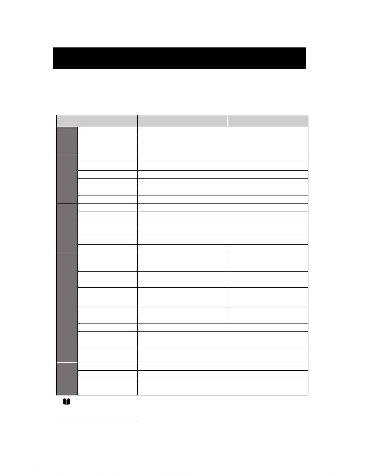
1. Product Types and Specifications
Category
S1002
S1006
Processing
& Memory
Processor
Dual ARM926EJ-S™ RISC Processor
Data Memory
128Mbit Stacked DDR SDRAM
Flash Memory
1Gbit
Sensor
Resolution
1280 X 960
Frame Rate
720P (1280 X 720) : 60frame/sec
Image Sensor
AR0134 (1/3 inch)
Pixel Size
3.75µm X 3.75µm
Shutter
Global
Output Format
RGB Bayer Raw (12Bit)
I/O Interface
Digital Output
3x Sink type output, Max sink 100mA, 60VDC (VAC Peak)
Digital Input
3x Opto-isolated input
Ethernet
100 Base-T
Serial Communication
RS-232C(EIA-232-C)
Video-out
CVBS1)
Light Control
Drive method : PWM control, 5 steps
·
Mechanical & Electrical Specs
Lens Type
8mm (F2.0)
C,CS-Mount
Manual Lens
Lens Mount
S-Mount (M12)
CS-Mount
Illuminator
Ring Type Built-in Illuminator
External Type
Power Consumption
Max 0.2A (24VDC) – illum. On
Max 0.1A (24VDC) – illum. Off
Max 0.1A (24VDC)
Dimensions
39.4mm X 41.0mm X 84.1mm
39.2mm X 39.2mm X 78.9mm
Weight
152g
120g
Housing
Aluminum, Plastic
Operating Ambient
Temperature
0°~ 45°C
Storage Ambient
Temperature
-30°~ 80°C
Software
Environment
Operating System
Windows 7, 8, 10
CPU
Core i3 or higher
RAM
4GB or higher
Monitor Resolution
1280 X 1024 or higher
Lens and illuminator are not included in S1006 model.
Please purchase them.
1)
Composite Video Baseband Signal
Ⅰ. Product Information

4
2. Product Components
inno-eye’s components are as follows.
1) Standard Components
Type
Common
Built-in Lens Type
CS-Mount Type
Built-in Lens Type
×1 ea.
Lens Focusing Jig
x 1 ea.
CS-Mount Type
×1 ea.
Adaptor Ring
for C-Mount inno-eye
×1 ea.
Product Information Guide
×1 ea.
Mounting Bracket ×1 ea.
Hexagon Socket
Head Bolt
for Mounting Bracket
(M4x6mm)×2 ea.
(plus 2 ea. as spares)
Using a bolt other than provided, it might cause mechanical failures or malfunctions.
Do not insert bolt into the bottom hole of inno-eye camera more than 4.0mm.
2) Control Box Kit (optional)
Control Box
(SSC-I01A)
Power Cable
(H3TC-K18F)
Screw Lock Type RJ45 Cable (3M)
(ZSCR-RJ45)
12 Pin Circular Cable (3M)
(HBSM-ACBA)
5
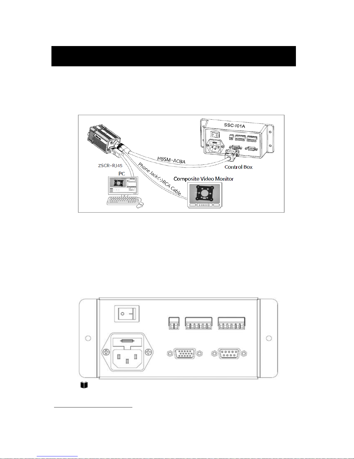
1. Hardware Configuration
inno-eye can be connected to Control Box2), and other accessories as follows :
1) Control Box
Control box is a device to supply Power to inno-eye and connect inno-eye with
other external devices. Control box is linked up with inno-eye through 12 pin
circular cable (HBSM-ACBA) provided. The method of connecting external
devices as follows:
For detailed information on Control Box, refer to the full Manual.
2)
Connect PLC with inno-eye Control Box for the inspection.
Ⅱ. System Configuration
Ext. INPUT
inno-eye
RS232
AC IN
Ext. OUTPUT
DC OUT
6
2) PC
PC is connected to inno-eye through the ethernet cable (ZSCR-RJ45) provided.
By using inno-eye Simulator installed in PC, we can setup inspection conditions
and monitor the results of inspection.
3) Composite Video Monitor
Video-out(CVBS) port on monitor is connected to inno-eye mono video out
port through Phone Jack ↔ RCA Cable, and used to monitor the inspection
results.
For detailed information, Please refer to the Full Manual Part 2. Instruction.
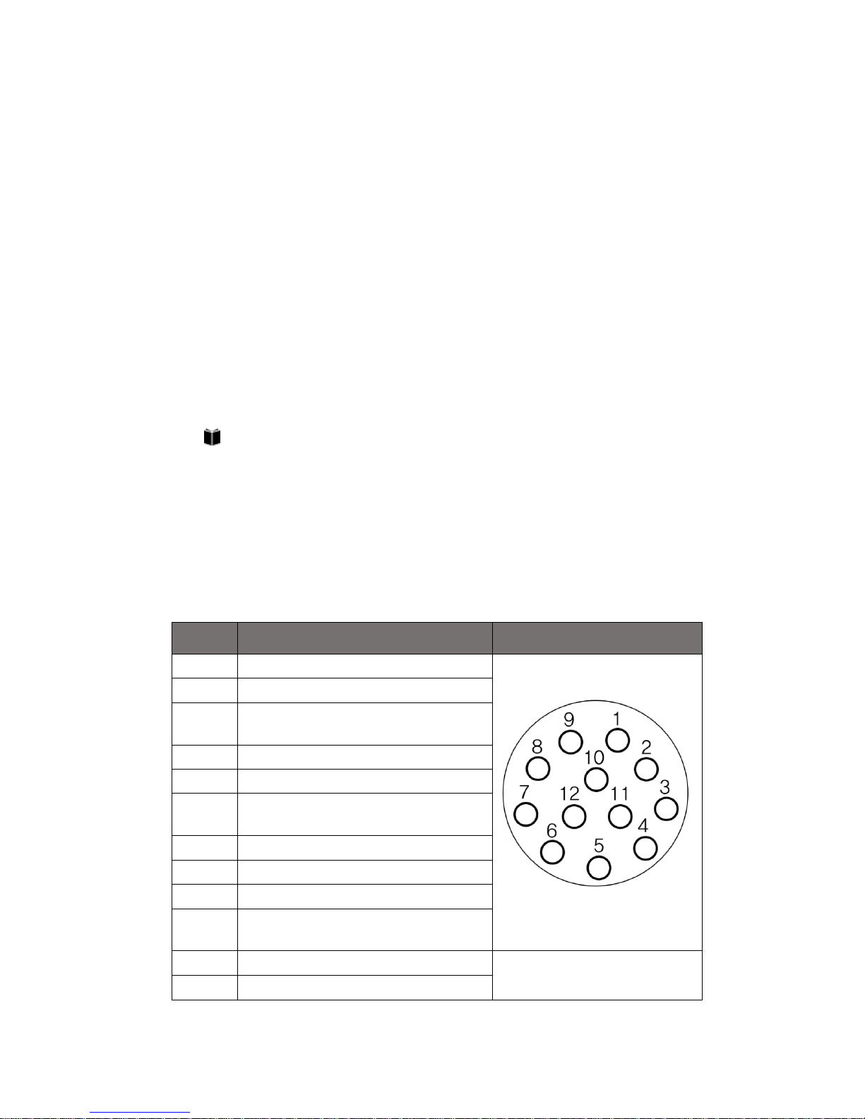
2. I/O Cable Pin Map
In case of not using a control box, you can connect inno-eye and PLC
(or corresponding process control devices) by referring to I/O cable pin map.
Pin No.
Signal Name
Connector Diagram
1
24VDC+ Input
2
GND Terminal
3
External Trigger Input Terminal
(EXT_TRIG)
4
External Input 0 (EXT_DI0)
5
External Input 1 (EXT_DI1)
6
Common Ground for Input Terminal
(EXT_DI_COM)
7
External Output 0 (EXT_DO0)
8
External Output 1 (EXT_DO1)
9
External Output 2 (EXT_DO2)
10
Common Ground for Output Terminal
(EXT_DO_COM)
11
232_RX(Serial Rx)
Backside 12 Pin Circular
Connector of inno-eye
12
232_TX(Serial Tx)

7
3. Installing inno-eye Simulator
Download inno-eye Simulator and install on PC3).
inno-eye Simulator can be downloaded at
http://inno-eye.coreicc.net/kr/support/support.php. After clicking
inno-eye download site, User enter client name, company name,
email address and click ‘’OK button’’, The compressed file including
inno-eye simulator and license key will be sent to the email
address entered.
User must install security module to use inno-eye simulator.
Security module is installed if User executes “driver_install.bat” file
that is included in sent compressed file. At this time, file “haspdinst.exe”
must be in same path where file “driver_install.bat” is located.
Installing security module takes about 1minute to 5 minutes.
But if user executes inno-eye Simulator without installing security module,
error occurs. In case of deleting security driver, User must
execute “driver_install_1.bat” and “driver_install_2.bat” in order.
Next, if user executes inno-eye Simulator, Message box appears to
inform user of registering “License Key”. Same message box will be
shown in case of clicking License Registration button at Connect inno-eye
Menu. License registration will be completed when user enter the license
3)
It is recommended to use Window 7 based PC or higher.
DONG IL TECHNOLOGY is not responsible for any failures or damages caused by not following
instructions described in this guide.
 Loading...