

Page 1

Transponder:
TRA, TRA.ROT, TRA.SCHALT, TRA.PWD
Published December 2006
Page 2

Transponder: TRA, TRA.ROT, TRA.SCHALT, TRA.PWD
Content
1.0 General Instructions .....................................................................3
Safety instructions................................................................... ........ .... .... .... ....3
1.2 Product description ........................................... ...................................4
1.1 Higher Priority Locking Level........................... ........ .... ... .... ........ .... ....5
2.0 Special Models ..............................................................................6
2.1 Password Transponder ............................................ .... .... ........ .... .... ....6
2.2 Switching Transponder........................................................................6
2.3 Explosion-Proof Transponder .............................................................6
2.4 Transponder, Sealed.............................................................................6
2.5 Transponder, Sequentially Numbered................................................6
3.0 Explosion-Proof Standards..........................................................7
3.1 General Information.............................................................. ................7
3.2 Standards................ ...............................................................................7
3.3 Grouping................................. ............................................... ................7
4.0 Additional Functions.....................................................................8
4.1 Time Zone Control ......................................... ........ .... ... .... ........ .... .... ....8
4.2 Validity Date...........................................................................................8
4.3 Activation Transponder........................................................ ................8
5.0 Battery Replacement.....................................................................9
5.1 Standard, Switching, and Password Transponders.......................... 9
5.2 Battery Replacement for the Explosion Protection Transponder ... 9
6.0 Loss of the Transponder..............................................................9
6.1 Emergency Opening .............................................................................9
6.2 Replacement Transponder.... ............................................... ................9
7.0 Programming and Reading the Transponder.............................9
7.1 Programming a Transponder.............................................................10
7.2 Reading a Transponder......................................................................10
8.0 Data Sheet....................................................................................11
Page 3

Page 3
1.0 General Instructions
Please take 15 minutes to familiarize yourself with how your Transponder works with the help
of these operating instructions.
Compliance Statement (Part 15.19)
This device complies with Part 15 of the FCC Rules.
Operation is subject to the following two conditions:
1. This device may not cause harmful interference, and
2. This device must accept any interference received, including interference that may
cause undesired operation.
Warning (Part 15.21)
Changes or modifications not expressly approved by the party responsible for compliance
could void the user’s authority to operate the equipment.
FCC Interference Statement (Part 15.105 (b))
This equipment has been tested and found to comply with the limits for a Class B digital
device, pursuant to Part 15 of the FCC Rules. These limits are designed to provide
reasonable protection against harmful interference in a residential installation. This
equipment generates uses and can radiate radio frequency energy and, if not installed and
used in accordance with the instructions, may cause harmful interference to radio
communications. However, there is no guarantee that interference will not occur in a
particular installation. If this equipment does cause harmful interference to radio or
television reception, which can be determined by turning the equipment off and on, the user
is encouraged to try to correct the interference by one of the following measures:
- Reorient or relocate the receiving antenna.
- Increase the separation between the equipment and receiver.
- Connect the equipment into an outlet on a circuit different from that to
which the r eceiver is connected.
- Consult the dealer or an experienced radio/TV technician for help
Industry Canada Statement per Section 4.0 of RSP-100
The term "IC:" before the certification / registration number only signifies that the Industry
Canada technic al spe ci f ications were met.
Section 7.1.5 of RSS-GEN
Operation is subject to the following two conditions:
1) this device may not cause harmful interference, and
2) this device must accept any interference received, including interference that may cause
undesired op er ation.
Safety instructions
o Caution! – The batteries used in this product could burn or cause a fire if they are not
handled properly. Do not charge, open or burn these batteries or heat to over 100°C.
o SimonsVoss Technologies, Inc. is not liable for any damage caused by incorrect
programming.
o An incorrectly programmed or faulty transponder can block access through a door.
SimonsVoss Technologies, Inc. is not liable for the consequences of such an
occurrence, such as blocked access to persons who are injured or in danger, material
damage or any other damage.
Transponder: TRA, TRA.ROT, TRA.SCHALT, TRA.PWD
Page 4
Page 4
1.2 Product description
Transponder: TRA, TRA.ROT, TRA.SCHALT, TRA.PWD
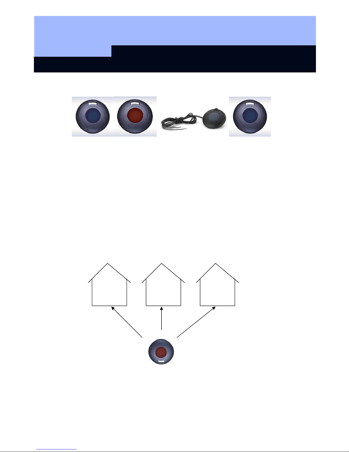
TRA TRA.ROT TRA.SCHALT TRA.PWD
Transponder Transponder Switching Transponder Password Transponder
Blue Button Red Button
The Transponder is activated when the user presses the button in the center of the device.
This device communicates an identity code to a SimonsVoss RF Lock or SmartRelay through
an encrypted, rolling-code radio signal. If the identification corresponds with one that is
authorized, the lock is unlocked or the SmartRelay is activated. The color of the button on the
transponder has no significance beyond appearance.
Since the Transponder’s communication is encrypted, it must be synchronized to the locks
with a common encryption signature. This is accomplished wh en it is programmed with the
configurat ion tool connected to the software used to define the lock system.
Each Transponder has the ability to support up to three unique lock systems independently.
This means that the user can use the same transponder on up to three different lock systems
even if each lock system has a different system administrator that has no communication with
the other two administrators.
Example:
Company Branch Private home
900 lockings 85 lockings 3 lockings
Page 5

Transponder: TRA, TRA.ROT, TRA.SCHALT, TRA.PWD
Page 5
1.1 Higher Priority Locking Level
If it is necessary to have transponders that are authorized for more than 3 mutually
independent lock systems, “higher priority lock levels” must be set up in these lock systems. A
maximum of 3 higher priority locking levels are available for this. All transponders of a higher
priority locking level have the same authorization. One digital lock distinguishes between a
maximum of three hig h er pr io r ity levels.
Example:
Higher priority transponder
In this example, four companies are accommodated in an office building with a central lock
that is used by all the companies. Each company administers its own lock system with its own
password. Every employee receiv es a transponder that is authorized for 2 lock systems,
namely the central lock and his or her own company.
However, the fire department, for example, needs a transponder that is authorized for all five
of the building’s lock systems. To accomplish this, a higher priority lock level with the same
password must be set up in all five lock systems and the authorizations must be set up for the
higher priority transponders. The transponders set up in this level all have the same
authorization. If higher priority transponders with other authorizations are required, an
additional higher priority lock level must be set up (max. 3 higher priority lock levels per lock!).
The higher priority transponder must then be programmed into all shutdown
systems.
Company D
Company C
Company B
Company A
Central
locking
system
s of all 5 lock
Page 6

Transponder: TRA, TRA.ROT, TRA.SCHALT, TRA.PWD
Page 6
2.0 Special Models
2.1 Password Transponder
Instead of manually entering the locking system password, you can transmit it over radio
frequency with the help of a special transponder. Standard transponders cannot be used as
password transponders.
The Password Transponder is special version that sends an encoded password rather than an
ID. The purpose of this device is to allow a system administrator to temporarily authorize
someone to use the programming software without actually disclosing the password. The way
this works is that the administrator encodes the password into this special transponder and
then gives the transponder to the temporary operator. When the system requests the
password, the new operator presses the button on the password transponder and the required
password is sent to the software with the SmartCD configuration tool acting as the reader.
When the temporary operator has completed his or her tasks and returns the password
transponder, that person no longer has access and the system administrator does not have to
worry that the password was compromised.
Warning: If the Password Transponder is ever programmed as a normal Transponder, it can
never again be used as a Password Transponder.
2.2 Switching Transponder
The Switching Transponder is identical to the Transponder with the addition of two wires
connected in parallel to the button on the device. These wires allow a third-party electronic
system to activate the Switching Transponder as if someone had pressed the button. The
button on the Switching Transponder remains usable.
2.3 Explosion-Proof Transponder
This is a transponder with the same functions as the standard transponder, but in addition, this
transponder can safely be used in an explosion protection zone 1.
(Note Chapter 3 in this regard).
2.4 Transponder, Sealed
This is the standard transponder as described above, but with the case glued shut. This
prevents end-users from opening the case and using the transponder electronics improperly,
but this also eliminates battery replacement so that the lifespan of the device is limited to the 1
million operations expected from the original battery.
2.5 Transponder, Sequentially Numbered
Sequentially numbered transponders can also be ordered if required.
Page 7

Transponder: TRA, TRA.ROT, TRA.SCHALT, TRA.PWD
Page 7
3.0 Explosion-Proof Standards
3.1 General Information
This special product is a transponder that is permitted to be carried into and used in areas
subject to explosion hazards, called Zone 1. An area is denoted as Zone
1 when atmospheres capable of exploding occur occasionally. It is crucial that you keep in
mind the following issues:
• The user is not permitted to open the housing.
• Unlike the standard Transponder, only SimonsVoss Technologies AG is
permitted to change the battery.
• Normally, you must comply with the general operating instructions of the BGR132
(German rules for occupational safety and health) when using the device in Zone 1.
3.2 Standards
The transponder has been tested according to the applicable explosion protection standards.
Refer to:
• Directive 94/9/EC
• DIN EN 50014 (Electrical apparatus for potentially explosive atmospheres)
• DIN EN 50020 (Intrinsic sa fety "i")
3.3 Grouping
The transponder is grouped in the following way:
• Explosion protection: zone 1
• Intrinsic safety: ib
• Explosion group: IIC
• Temperature class: T3
• Device group: II2 G
This applies to areas in which a potentially explosive atmosphere can arise due to gases,
vapors or mists. The information quoted relates to an ambient temperature of from -4°F to
+104°F (-20°C to +40°C) where the transponder is used.
Page 8

Transponder: TRA, TRA.ROT, TRA.SCHALT, TRA.PWD
Page 8
4.0 Additional Functions
The following functions can be activated in the lock plan software:
4.1 Time Zone Control
If the Time Zone Control has been enabled in the SimonsVoss RF locks, you can program
transponders that have lock authorization for specific times only. These time zones are
deposited in the lock plan software, and the transponders are then assigned to an appropriate
time zone group.
Example: Mr. Miller receives the following authorization:
Monday to Friday from 9:00 am, until 6:30 p.m.
Saturday from 9:00 am, until 12:45 p.m.
Sunday no authorization
4.2 Validity Date
It is possible to program transponders whose authorization is tied to a validity date:
¾ Transponders that are valid from a specific point in time
(i.e. from 8:00 a.m. on July 12, 2003)
¾ Transponders that are valid up to a specific point in time
(i.e. until 5:00 p.m. on July 12, 2003)
¾ Transponders that are valid for a specific time interval
(i.e. from July 1, 2003 until July 31, 2003)
Note: One data record is assigned for each activation or expiration date!
4.3 Activation Transponder
Within the scope of the block lock function, all authorized transponders for a SimonsVoss RF
lock in the security area are blocked when the alarm system has been activated in order to
avoid false alarms. For emergency situations, transponders can be programmed (for example,
for the fire department) that release this block. Afterwards, the door can be opened with an
authorized transponder.
Page 9

Transponder: TRA, TRA.ROT, TRA.SCHALT, TRA.PWD
Page 9
5.0 Battery Replacement
5.1 Standard, Switching, and Password Transponders
It is possible to damage the transponder if battery replacement is handled incorrectly. This
procedure should only be attempted by a trained electronic technician. If it takes you longer
than two minutes or if the battery terminals are shorted, the data in the transponder will be lost
and the transponder must be reprogrammed.
Before opening the transponder make sure that you are electrically grounded with an
approved anti-static heel or wrist strap. Electrostatic discharge can destroy or shorten the life
of a transponder. The SimonsVoss Technologies, Inc warranty does not cover damage
caused by improper battery replacement.
To replace the batteries, gently pry the case apart by inserting a fingernail or knife blade into
the seam at the “equator” of the device. When the case has been opened you will see the
battery held to the board by a clip.
Orient the device so that the keychain hole is at the top and the antenna is to your right.
Remove the clip by gently pressing on the bottom of the clip while sliding it to the left. The
bottom of the clip should then be able to be pulled up and away from the board, allowing the
battery to be removed.
When inserting the new battery, make sure that the polarity is correct with the positive terminal
up (the large side with the writing is the positive terminal).
Replace the retaining clip being sure to press gently and slide it to the right to re-engage the
tension on the battery.
Replace the cover on the transponder. Read the transponder to verify that the data is still
intact.
5.2 Battery Replacement for the Explosion Protection Transponder
Attention:
Only SimonsVoss Technologies, AG is permitted to change the battery for an Explosion Proof
Transponder! Any attempt to change the battery outside SimonsVoss production facilities
voids its use as an explosion-proof device.
6.0 Loss of the Transponder
6.1 Emergency Opening
An emergency opening can be carried out using the SmartCD + PDA (only use devices
approved by SimonsVoss) and knowledge of the lock system password.
6.2 Replacement Transponder
If a transponder is lost, it can be deleted from the lock plan and a replacement transponder
can be set up. When operating the lock system in overlay mode, the lost transponder is
automatically blocked as soon as the replacement transponder is activated at the RF lock.
7.0 Programming and Reading the Transponder
Page 10

Transponder: TRA, TRA.ROT, TRA.SCHALT, TRA.PWD
Page 10
See the appropriate software manual to learn the details of how to program and read the
transponder but the following should be helpful.
7.1 Programming a Transponder
Before it can be used with a lock system, the Transponder must be programmed. This programming is necessary to give it the identification code assigned by the lock system and to
give it the encryption key appropriate to that system.
Before you can program a transponder you must be authorized to do so. This is accomplished
in the SimonsVoss software by selecting the function titled Authorize Transponder Programming and providing the appropriate password.
To program a transponder, it must be placed within 18 inches but no closer than four inches to
the configuration tool, which is connected to the computer running the programming software.
In the SimonsVoss software select the transponder you want to program on the lock plan by
left-clicking on the transponder name; resulting in that transponder being highlighted.
Select the function titled Program Transponder. A dialog will appear and you should confirm
that the appropriate transponder is indicated before pressing the Program button. If for some,
reason, the transponder listed is not the correct one, simply select the correct one from the
combo box before proceeding. The software will then direct you to press the button on the
transponder one or more times. Follow the instructions and the software will tell you whether
the procedure was successful or not.
If it was not successful, the reasons may be one of the following:
1) The transponder was too close to the configuration tool – move the transponder at least 4
inches away from the configuration tool and try again.
2) The transponder has already been programmed for three different systems – to use with
this system the transponder must be reset (losing the other programming information).
3) There is too much RF interference – move the computer, configuration tool, and trans-
ponder to another location and try again.
7.2 Reading a Transponder
Before it can be used with a lock system, the Transponder must be programmed. This programming is necessary to give it the identification code assigned by the lock system and to
give it the encryption key appropriate to that system.
After the lock has been programmed, the Transponder can be read and will disclose the user
name and time restrictions, if any. If the Transponder is unknown to the lock system, reading
it will result in the display of the SID (system identification) and TID (transponder identification).
In order to read a transponder, select the Read Transponder function in either the LDB or LSM
software. This function will direct you to press the button on the Transponder and will then
display the result.
Page 11

Page 11
8.0 Data Sheet
Dimensions: H x W x D
Weight
Color
Operating distance, RF Locks approx. 16 inc hes (40 cm) if the transponder,
Operating distance,
SmartRelay
Protection category
Operating temperature range
Battery type
Transponder: TRA, TRA.ROT, TRA.SCHALT, TRA.PWD
1.7 in diameter x 0.5 in thick
(42 mm diameter x 13 mm thick)
0.5 oz (15 g)
Dark Grey, with blue button
lengthways, is held parallel with the RF Lock
antenna
approx. 47 inches (120 cm) if the transponder is
parallel with the antenna of the SmartRelay
IP 54 (NEMA 3S)
-4°F to 104°F (-20°C to 40°C)
Noncondensing
3 V DC lithium battery type CR2032
 Loading...