

Page 1

TRANSPONDER TERMINAL
MANUAL
Version: July 2012
Page 2

TRANSPONDER TERMINAL
MANUAL
1.0 PRODUCT DESCRIPTION ______________________________3
1.1 ORDER CODE ___________________________________________ 3
1.2 DESCRIPTION ___________________________________________ 3
2.0 WARNING ___________________________________________4
2.1 SAFETY ________________________________________________ 4
2
3.0 INSTALLATION_______________________________________5
3.1 IMPORTANT ____________________________________________ 5
3.2 DIAGRAM_______________________________________________ 6
3.3 INSTALLATION PROCEDURE ______________________________ 7
4.0 CONNECTIONS_______________________________________8
5.0 INITIAL OPERATION __________________________________8
6.0 OPERATION _________________________________________9
7.0 BUTTON ___________________________________________10
7.1 EVENT ________________________________________________ 10
7.2 POWER-UP RESET______________________________________ 10
7.3 FACTORY DEFAULT RESET ______________________________ 11
8.0 DATA SHEET _______________________________________11
Page 3
TRANSPONDER TERMINAL
MANUAL
1.0 PRODUCT DESCRIPTION
1.1 ORDER CODE
TRATERM
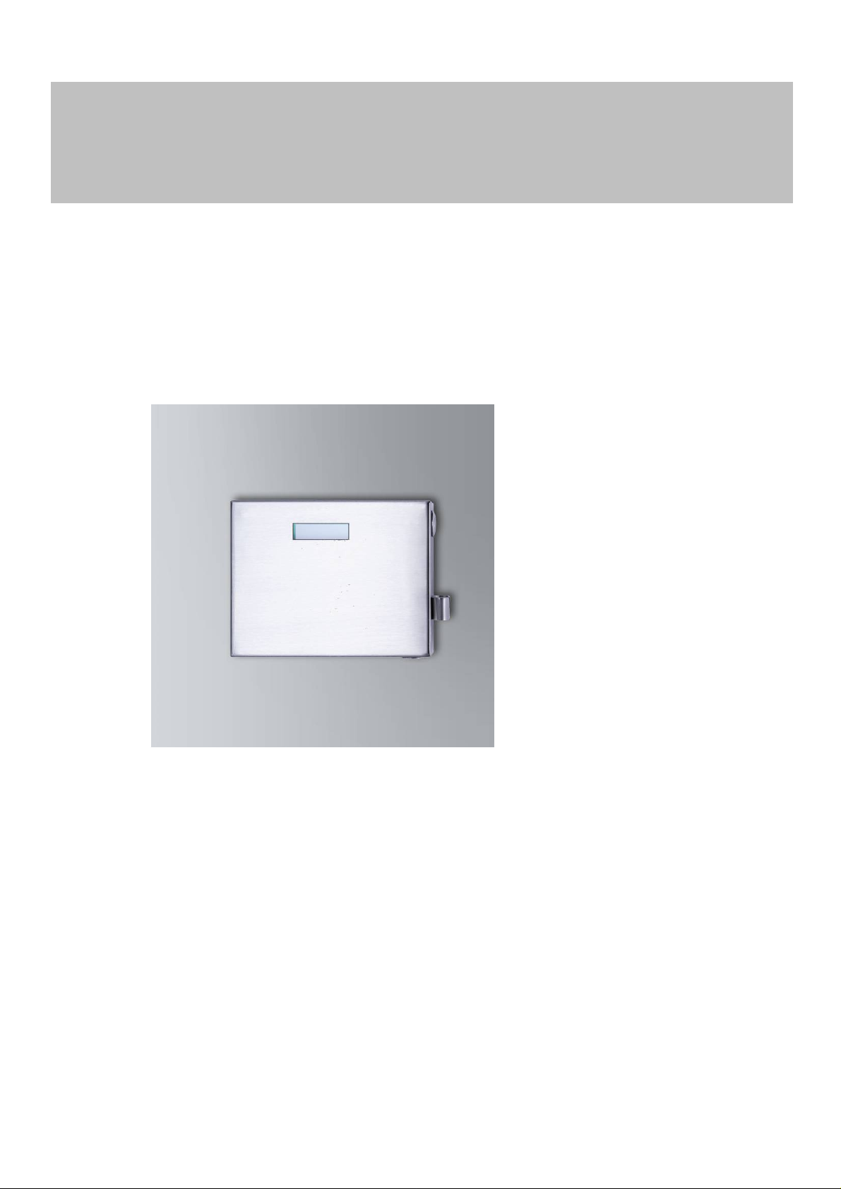
1.2 DESCRIPTION
3
A transponder terminal is a network-ready, vandal-proof, external programming device for use outdoors which can help to automatically re-programme active SimonsVoss transponders without the need for the locking system administrator to be directly
involved in the programming process or be present where it takes place.
Page 4

TRANSPONDER TERMINAL
MANUAL
2.0 WARNING
2.1 SAFETY
− Specialist knowledge in access control systems, door mechanics, door
approvals and the use of SimonsVoss software is required when installing
a SimonsVoss transponder terminal. This is why only trained specialists
may install this terminal.
− SimonsVoss Technologies AG accepts no liability for damage caused by incorrect installation.
− Do not allow the Smart Handle to come into contact with oil, paint or acids!
4
− Do not try to open the device.
− Do not drop the device; protect it against impacts and do not shake. If you han-
dle the terminal carelessly, you may damage the electrical circuits and mechanical components inside.
− When installing the device, ensure no water or damp can get into the housing.
− Access through a door may be blocked due to defective or incorrectly installed
transponder terminals. SimonsVoss AG is not liable for consequences of incorrect installation, such as blocked access to injured persons or those at risk,
physical damage or any other losses.
− The transponder terminal must be installed in compliance with ESD (electrostatic
discharge) guidelines. You should particularly ensure that you do not touch the
circuit boards and their integrated circuits.
− Do not pull on the cables.
− SimonsVoss further develops its products on a continuous basis. SimonsVoss
Technologies AG reserves the right to make changes to any of the explanations
and functions described in this manual without prior notice.
− This documentation has been compiled in accordance with the best knowledge
available to us. However, errors cannot be ruled out. No liability is accepted in
such cases.
− Should there be differences in the content of other language versions of this
documentation, the German version applies in cases of doubt.
Page 5

TRANSPONDER TERMINAL
MANUAL
3.0 INSTALLATION
3.1 IMPORTANT
− When installing the transponder terminal, ensure that there are no sources of
low-frequency interference in the surrounding area.
− When installing the device, ensure no water or damp can get into the housing.
− Do not pull on cables and ensure that they do not become caught or broken and
are not damaged in any other way.
− When installing the terminal, place it in such a way that it is fitted in a horizontal
position.
− To prevent the housing outside from being rotated or removed from the wall, a
mounting plate - a perforated metal sheet to provide optimum flexibility - is
screwed onto the building's exterior wall as an anti-rotation protection element
before the terminal housing is put into place. This plate also compensates for
any uneven surface on the wall.
− The plate fits into the recess on the rear of the terminal housing and prevents it
from being rotated.
− The threaded rod has an M10 thread.
− The threaded rod consists of three sections, which can be flexibly adjusted to
match the wall thickness.
− The drawing is for guidance only and may differ from the original product.
5
Page 6
TRANSPONDER TERMINAL
MANUAL
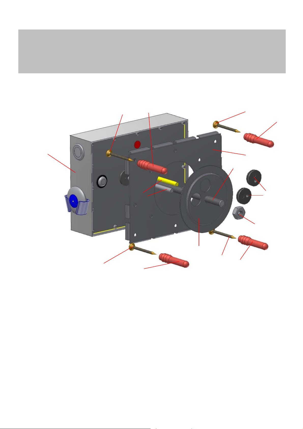
3.2 DIAGRAM
1
6
5
6
6
5
2
3
4
6
1. Transponder terminal
2. Perforated sheet
3. Threaded rod (2x long, 1x short)
4. Cable (2 x)
5. Wall plugs
6. Screws
7. Fastening plate
8. Nut
9. Rubber seals
5
7
6
9
8
5
Page 7

TRANSPONDER TERMINAL
MANUAL
3.3 INSTALLATION PROCEDURE
Install as follows:
1. Drill a (core) hole about 30 mm in diameter through the wall.
2. Clean the hole as much as possible, so that it actually has a 'real' diameter of
about 30 mm.
Optional: also push a plastic tube about 30 mm in diameter through the hole to
protect the cable from chafing. Note: this tube is not supplied with the product.
3. Hold the perforated sheet (2) in the centre horizontally over the (core) hole, so
that the centre of the circular cut-out in the perforated sheet (2) and the hole in
the wall match.
4. Mark at least 4 other holes through the perforated sheet (2).
5. Drill at least four 6 mm blind holes, as marked in Step 4 above, into the wall.
6. Fasten the perforated sheet (2) to the wall using wall plugs (5) and screws (6).
The holes in the perforated sheet (2) are designed to hold M6 screws as a
maximum size.
7. Depending on the wall thickness, use 1, 2 or 3 sections of the threaded rod
and attach supplied union nuts (not shown in the diagram).
8. Fasten the threaded rod (3) to the rear of the transponder terminal (1) and
tighten by hand (about 5-7 Nm).
9. Attach the ends of the interface cable (4) to the top of the threaded rod (3)
with adhesive tape, for instance.
10. Carefully push the threaded rod (3) and the cable (4) through the hole. In doing so, you must ensure that the cable does not get caught or broken, or damaged in any other way.
11. Push the threaded rod through until the transponder terminal (1) lies as flat as
possible on the perforated sheet (2). Push the cable through at the same time,
ensuring it does not get damaged in any way.
12. From inside the building, carefully pull the cable (4) all the way inside.
13. Pull the cable (4) on the inside wall through the two outer openings in the inside fastening plate (7).
14. Place the middle opening of the fastening plate (7) over the threaded rod (3)
and push the plate until it lies flat against the wall. In doing so, also push the
cable (4) through and ensure that the cable does not get caught or broken, or
damaged in any other way.
15. Screw the transponder terminal (1) tightly into position with the lock nut (8).
Tighten the lock nut firmly by hand (5-7 Nm) to prevent the terminal from coming loose.
Optional: use a thread-locking fluid or self-locking screws. Neither self-locking
screws nor thread-locking fluids are included in the supply package.
16. Check to see if the transponder terminal (1) can be rotated or pulled from the
wall on the outside. If it is still loose, fasten the nut (7) even tighter.
17. Pull the rubber seals (9) over the two cables and press them into the two
openings in the fastening plate (7), so that they seal the holes.
Fastening the transponder terminal with the perforated sheet, threaded rod and nut
means it is no longer possible to remove the terminal on the outside. The terminal can
be dismantled using the same procedure, but in reverse.
7
Page 8

TRANSPONDER TERMINAL
MANUAL
4.0 CONNECTIONS
The following connections are available or are supplied with the transponder terminal,
ready installed and connected.
• RJ45 plug (for the network connection)
• 3-pole power supply
o Blue Æ + 48V
o Brown Æ - GND (mass)
o Green/yellow Æ Ground
The connecting cable is labelled as such, features wire end ferrules and is 1.5 m long.
Please ensure that you do not pull on the cables and that they are not subject to any
other type of tensioning.
5.0 Initial operation
Please refer to the LSM Transponder Terminal manual for initial operation with the
software and integration into the LSM application.
8
Page 9
TRANSPONDER TERMINAL
MANUAL
6.0 OPERATION
3
9
2
1
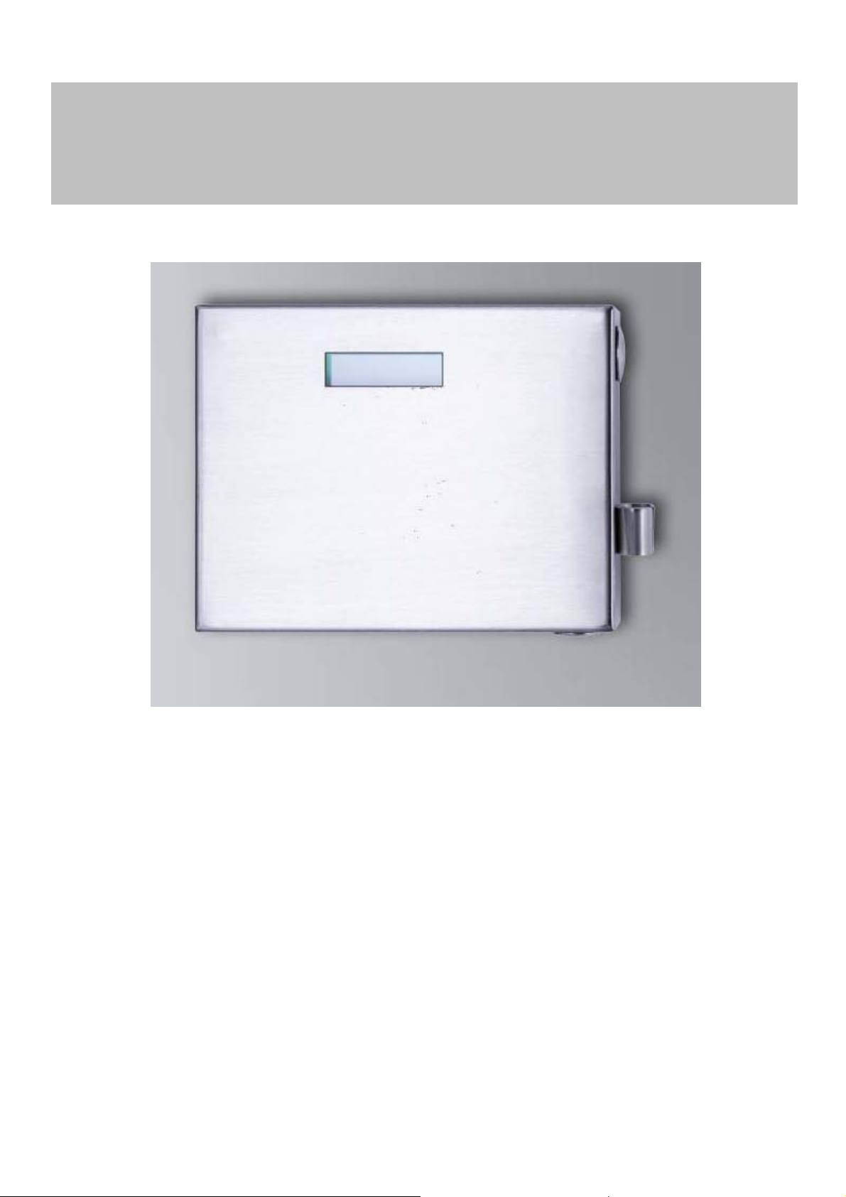
To ensure that the transponder is programmed correctly without any errors, you must
place the transponder in the transponder bracket (1) and not hold it in your hand or
place it on top of the housing. The bracket holds the transponder in a position where
the range and alignment are optimally matched. The transponder bracket (1) is attached to the right-hand side of the housing.
Please proceed as follows when operating the transponder terminal:
• Position transponder in the transponder bracket (1) with the key ring pointing
downwards
• Press event button (2) on the right-hand side of the housing
• Follow the instructions on the display (3)
Do not remove the transponder until the programming process is complete, otherwise
this may lead to incorrect programming and malfunctions at the door. The display will
indicate when programming is complete.
Page 10

TRANSPONDER TERMINAL
MANUAL
7.0 BUTTON
10
1
7.1 EVENT
The event button (1) is on the right-hand side of the housing and is used to start the
programming process or start communication between the transponder terminal and
the programming software via the IP network.
7.2 POWER-UP RESET
The power-up reset button (2) is positioned on the lower surface of the housing. This
button can be used to interrupt the power supply temporarily. The device is then restarted. A restart is recommended if the device gets stuck or the terminal does not
continue with the programming process after a short interval when the event button
has been pressed. You must complete all steps in 5.0 before programming transponders.
If programming does not launch, this may also be due to a problem with the network
or there are no programming tasks in the LSM. In case of doubt, contact the locking
system administrator.
2
Page 11

TRANSPONDER TERMINAL
MANUAL
7.3 FACTORY DEFAULT RESET
The factory default reset button is positioned on the rear of the housing and may only
be used during installation. This is only used to reset to the factory default setting if
the terminal has been configured incorrectly.
Important: if you press this button, you will always need to re-configure the device.
This may not be possible at the actual installation location.
8.0 DATA SHEET
Housing dimensions [W x D x H]: 182 x 50 x 142 mm
Weight: about 1,440 g
Housing material: Stainless steel (1.4301)
Colour: Stainless steel
Protection rating: IP65
Temperature range: -40°C to +40°C
Storage temperature: -40°C to +85°C
Power supply 5V / 2.5A
Power supply unit: 48V DC
Display: 2-line LCD
Buttons: Event button
Cable length: 1.5m
Cable type: Cat. 5E
Plugs: a) RJ45
2 colours
Protected with safety glass
Reset button
Factory default button
b) Power supply:
• Blue Æ + 48V
• Brown Æ - GND (mass)
• Green/yellow Æ Ground
11
 Loading...