

Page 1

Manual
SmartRelais 3 Advanced
08.2018
Page 2

Contents
1 Intended use ....................................................................................................................................5
2 Safety instructions..........................................................................................................................6
3 System description .........................................................................................................................8
3.1 Controller................................................................................................................................8
3.2 Reader.................................................................................................................................... 9
3.3 SmartOutput module ............................................................................................................ 10
3.4 Versions ...............................................................................................................................10
3.5 Accessories .......................................................................................................................... 11
4 System requirements....................................................................................................................13
5 Connections ..................................................................................................................................14
5.1 Controller..............................................................................................................................14
5.2 Reader.................................................................................................................................. 15
5.3 SmartOutput module ............................................................................................................ 16
6 Setting up.......................................................................................................................................19
6.1 Unpacking and system test .................................................................................................. 19
6.2 Configuration ........................................................................................................................ 19
6.2.1 Establishing IP settings .............................................................................................23
6.2.2 Creating a communication node................................................................................ 23
6.3 Programming........................................................................................................................24
6.3.1 Adding SmartOutput modules ...................................................................................26
6.3.2 Resetting the controller .............................................................................................28
6.4 Application examples ...........................................................................................................33
6.4.1 Basic principle ...........................................................................................................33
6.4.2 Gateway function....................................................................................................... 34
6.4.3 General overview ......................................................................................................34
6.4.4 Solutions for scenarios .............................................................................................. 36
6.4.5 wiring ......................................................................................................................... 55
7 Installation .....................................................................................................................................78
8 SREL3 ADV in LSM .......................................................................................................................79
8.1 Changing over from SREL2 to SREL3.ADV......................................................................... 79
8.2 Access list ............................................................................................................................79
8.2.1 Import access list....................................................................................................... 79
8.2.2 Resetting the access list............................................................................................ 83
8.2.3 Event logging of unauthorised accesses...................................................................84
8.3 Flip-flop................................................................................................................................. 84
8.4 Time budgets........................................................................................................................ 85
Manual
SmartRelais 3 Advanced
2 / 135
SimonsVoss
Contents
Page 3

8.4.1 Time budget template for new locking system identification media ..........................85
8.4.2 Ignoring activation/expiry date................................................................................... 86
8.5 Consequences in the event of a network failure ..................................................................86
8.6 Signal settings ...................................................................................................................... 87
8.7 Operation as interface .......................................................................................................... 88
8.8 Near-field option ................................................................................................................... 89
8.9 Switching interval .................................................................................................................89
8.10 Software reset ...................................................................................................................... 90
8.11 Time switch-over function..................................................................................................... 91
8.11.1 Extended configuration without SmartOutput module ............................................... 93
8.11.2 Extended configuration with SmartOutput modules ..................................................94
8.12 Remote opening ................................................................................................................... 95
8.13 Firmware update ..................................................................................................................98
8.14 Events ..................................................................................................................................98
8.14.1 Evaluating controller inputs .......................................................................................98
8.14.2 SmartSurveil............................................................................................................101
8.15 Things to do........................................................................................................................ 103
8.15.1 Initial programming via TCP/IP................................................................................ 103
8.15.2 Different authorisations on transponders ................................................................104
8.15.3 Signalling for flip-flop ............................................................................................... 107
9 Signal ...........................................................................................................................................110
10 Maintenance ................................................................................................................................111
10.1 Battery warning ..................................................................................................................111
10.1.1 Reading the battery level with USB cable ...............................................................111
10.1.2 Reading the battery level over network ................................................................... 113
10.2 Battery replacement ........................................................................................................... 115
11 Fault rectification ........................................................................................................................117
11.1 Resetting components........................................................................................................ 117
11.2 Broadcast error................................................................................................................... 117
11.3 Permanent relay switching in the SmartOutput module ..................................................... 119
11.4 Problems with inputs or network readout/programming..................................................... 119
11.5 Time change-over does not respond to change................................................................. 120
12 Technical specifications.............................................................................................................121
12.1 Order numbers ................................................................................................................... 121
12.2 Properties ........................................................................................................................... 121
12.2.1 Controller.................................................................................................................121
12.2.2 Reader..................................................................................................................... 124
12.2.3 SmartOutput module ...............................................................................................125
12.2.4 Recommended cable types.....................................................................................127
Manual
SmartRelais 3 Advanced
3 / 135
SimonsVoss
Contents
Page 4

12.3 Power input in practice ....................................................................................................... 128
12.4 Dimensions......................................................................................................................... 130
12.4.1 Controller.................................................................................................................130
12.4.2 Reader..................................................................................................................... 131
12.4.3 SmartOutput module ...............................................................................................132
12.5 Drilling templates................................................................................................................132
12.5.1 Controller.................................................................................................................133
12.5.2 Reader..................................................................................................................... 134
13 Help & Contact ............................................................................................................................135
Manual
SmartRelais 3 Advanced
4 / 135
SimonsVoss
Contents
Page 5

Manual
SmartRelais 3 Advanced
5 / 135
SimonsVoss
1 | Intended use
1 Intended use
In its third generation, the SimonsVoss SmartRelay system (SREL 3 ADV)
is a system consisting of several networked components which provide
intelligent control of locking devices and third-party systems. The system
consists of a controller, at least one external reader and an optional
SmartOutput module.
The controller is the main component. A service communicates with the
LSM database and provides the controller with the latest information from
the database when it is used as a gateway. No manual updates or timeconsuming reprogramming are required.
The controller can use information retrieved from the LSM database and
identification data transmitted by the reader to verify identification data with
the database. Different actions are possible, depending on the settings
programmed in the controller, including:
– Assigning authorisations
– Withdrawing authorisations
– Loading time budgets
– Updating identification media configurations
– Switching relay outputs
– Reading lists
Identification media are read by up to three external readers, which may be
physically separate from one another and the controller. In the thirdgeneration SmartRelay system, the reader can read active and passive
identification media and transmit the information to the controller for
evaluation.
The controller features a built-in relay output which can be freely
programmed. The system can be extended with SmartOutput modules in a
daisy chain featuring up to 116 relay outputs, which are also freely
programmable.
Page 6
Manual
SmartRelais 3 Advanced
6 / 135
SimonsVoss
2 | Safety instructions
2 Safety instructions
DANGER
Risk of injury due to incorrect programming
The SREL3 ADV system is not suitable to replace existing security installations.
1. Ensure that the SREL3 ADV system is used as an additional securing
measure only.
2. Do not replace existing security installations with the SREL3 ADV
system.
WARNING
Blocked access
Access through a door may be blocked due to incorrectly fitted or incorrectly programmed components. SimonsVoss Technologies GmbH is not liable for the consequences of incorrect installation, such as physical damage or any other losses, or blocked access to injured persons or those at
risk.
CAUTION
Fire hazard posed by batteries
The batteries used may pose a fire or burn hazard if handled incorrectly.
1. Do not try to charge, open, heat or burn the batteries.
2. Do not short-circuit the batteries.
CAUTION
Risk of burns due to hot circuit board
The circuit board can become very hot if PoE is used (power supply over
Ethernet).
1. Let the controller cool down before you open the housing.
ATTENTION
Misuse
SmartRelay may only be used for its intended purpose. No other use is permitted.
IMPORTANT
SimonsVoss Technologies GmbH accepts no liability for damage caused to
doors or components due to incorrect fitting or installation.
IMPORTANT
Specialist knowledge in door mechanics, door approvals, electronic system
installation and the use of SimonsVoss software is required to install the
system and put it into operation. Only trained specialists may install the
system.
Page 7

Manual
SmartRelais 3 Advanced
7 / 135
SimonsVoss
2 | Safety instructions
IMPORTANT
This documentation has been compiled based on the best knowledge available to us. Nevertheless, errors cannot be ruled out. SimonsVoss Technologies GmbH is not liable in such cases.
IMPORTANT
Should there be differences in the content of other language versions of
this documentation, the German version applies in cases of doubt.
IMPORTANT
You must follow all instructions precisely when connecting and installing the
product. The person installing the system should hand these instructions as
well as any maintenance instructions over to the user.
IMPORTANT
Modifications or further technical developments cannot be excluded and
may be implemented without notice.
Page 8

Manual
SmartRelais 3 Advanced
8 / 135
SimonsVoss
3 | System description
3 System description
3.1 Controller
The SREL3 ADV system is connected to the network via Ethernet. The
Ethernet connection is PoE-capable, so an external power supply unit is not
essential. It is possible to use the system as a gateway in the virtual
network. The controller established a connection to the VN host server to
do so. The VN host server transmits modified authorisations (programming
requirement) and data from the LSM database to the controller. This means
there is no longer a need for the database to be fully loaded, which saves
time. Instead, the controller fetches the provided data when an identification
medium is detected (pull principle). The entire system is programmed via a
single interface – the controller.
The SREL3 ADV is also available in a ZK variant, which extends the
system's functions to include time zone control and event logging (access
lists).
Three available screw terminal inputs ensure that the controller is flexible in
its use.
– Forwarding to LSM (Inputs 1 and 2)
– Push-to-open contact (Input 3)
The built-in screw terminal relay output can activate any system and open
an electric door, for example.
An IP address needs to be issued using USB when the controller is
programmed for the first time. Once the IP address is issued, a USB
connection is no longer needed. The controller's configuration can be
modified over the network instead.
The built-in backup battery ensures that the programmed settings are
maintained after a power failure and guarantees that the controller
continues to function without any limitations once power is restored.
Page 9

Manual
SmartRelais 3 Advanced
9 / 135
SimonsVoss
3 | System description
IMPORTANT
Follow the switch-on sequence
After a power-on reset (power outage followed by restoration of power supply), the controller automatically searches for connected system components one time on restarting. System components which are not supplied
power until the controller restarts are thus unable to respond to the controller's query and are not recognised.
The controller must therefore be supplied power with the other system components at the same time or must be the last system component to receive
power.
3.2 Reader
At least one external reader is required to use the SREL3 ADV system.
SmartRelay 3 readers are ordered separately from the controller.
The controller is unable to read identification media. Up to three readers
can be connected via an RS-485 interface for this purpose. They can read
both active and passive identification media. After reading media, the
readers transmit the data to the controller, which checks the identification
medium's authorisation and triggers relevant actions as programmed. The
reader itself is unable to trigger actions and can thus be installed in less
protected areas. In the WP variant, the housing is sealed and protected
against splashing water.
Readers can either be powered through the controller or equipped with
their own power supply unit.
IMPORTANT
Too low operating voltage
When selecting the power supply, please allow for a voltage drop occurring
in conductors. A voltage drop can cause the operating voltage in the reader
to fall below the required level and malfunctions may occur. In such a case,
either the operating voltage on the controller needs to be increased or the
reader equipped with its own power supply unit.
A multi-coloured LED signals the different operating modes.
Page 10

Manual
SmartRelais 3 Advanced
10 / 135
SimonsVoss
3 | System description
3.3 SmartOutput module
SmartOutput modules are ideal complements to controllers if more than
one relay output is required. Every SmartOutput module is equipped with
eight relays, which each feature a change-over contact. SmartOutput
modules can be connected in parallel to one another and fitted on a DIN rail
(35 mm x 7.5 mm).
A multi-coloured LED signals the different operating modes.
IMPORTANT
Follow the switch-on sequence
After a power-on reset (power outage followed by restoration of power supply), the controller automatically searches for connected system components one time on restarting. System components which are not supplied
power until the controller restarts are thus unable to respond to the controller's query and are not recognised.
The controller must therefore be supplied power with the other system components at the same time or must be the last system component to receive
power.
3.4 Versions
Several improvements have been made for the newly launched SREL 3
ADV compared to its predecessor:
Comparison between SmartRelay 2 and SmartRelay 3
SmartRelay 2 SmartRelay 3 Advanced
Duration of data transmission to the gateway
– Depending on the
data volume (push
principle)
– Immediate (pull
principle)
Page 11

Manual
SmartRelais 3 Advanced
11 / 135
SimonsVoss
3 | System description
Comparison between SmartRelay 2 and SmartRelay 3
Interfaces
– Wiegand, 33 bit
– Wiegand, 26 bit
– Primion
– Siemens Cerpass
– Kaba Benzing
– Gantner Legic
– Isgus
– Wiegand, 33 bit
– Wiegand, 26 bit
– Primion
– Siemens Cerpass
– Kaba Benzing
– Gantner Legic
– Isgus
Components required
for networking
– Controller
– Reader
– LockNode
– Router
– Controller
– Reader
Networking – LockNode – Ethernet (integrated)
Power supply – 9–24 VDC
– 9-32 VDC
– PoE
Number of relay contacts
– 1
– Up to 116+1 (with
SmartOutput
modules)
Number of external
readers
– Max. 2 – Max. 3
Programming – SmartCD
– Ethernet
– USB (with power
adapter)
3.5 Accessories
You can adapt the SREL3 ADV system to different purposes with optional
accessories. The following accessories can be ordered:
Order code Name Purpose
MOD.SOM8 SmartOutput module
The SmartOutput module increases the number of switchable relay
outputs to up to 116+1
outputs.
POWER.SUPPLY.2
Power supply unit
(12VDC, 500mA)
This power supply unit
can be used to power
the controller.
Page 12

Manual
SmartRelais 3 Advanced
12 / 135
SimonsVoss
3 | System description
Order code Name Purpose
SREL2.COVER1 Anti-vandalism housing
Fastened with special
screws, this housing is
also suitable for the
SREL3 ADV system. It
protects the SREL3
ADV system reader
against the weather and
vandalism.
Page 13

Manual
SmartRelais 3 Advanced
13 / 135
SimonsVoss
4 | System requirements
4 System requirements
LSM 3.3 SP2 or higher (Basic Online, Business or Professional) is required
to programme SmartRelay 3.
The VN host must be installed and running, so that the controller can
retrieve data and programming requirements from the database via the VN
host in gateway mode.
The controller requires a TCP/IP connection to the server for operation:
– 10/100 MB/s
– Latency typ. < 10 ms
Connection to faster networks is possible provided they are backwardscompatible.
.NET-Framework Version 4.0 or higher must be installed to use the
CommNode or VN host server.
If LSM Basic Online is used with a virtual network, then LSM Basic Online
must be run in administrator mode.
Page 14

Manual
SmartRelais 3 Advanced
14 / 135
SimonsVoss
5 | Connections
5 Connections
5.1 Controller
1
2
3
4
5
6
7
8
9
10
11
12
13
14
15
16
17
18
19
20
21
22
23
24
25
26
27
28
29
30
No.
Circuit
board
Explanation
1 -
GND. Optional connection to an external power supply
(earth).
2 +
VIN. Connection to an external power supply (positive
terminal).
3
Relay 1: NO (normally open). This contact is connected
to C when the relay switches.
4
Relay 1: C (common). Shared connection to changeover contacts.
5
Relay 1: NC (normally closed). This contact is disconnected from C when the relay switches.
6
Relay 2: NO (normally open). This contact is connected
to C when the relay switches. Availability for actuation
depends on the firmware.
7
Relay 2: C (common). Shared connection to changeover contacts. Availability for actuation depends on the
firmware.
8
Relay 2: NC (normally closed). This contact is disconnected from C when the relay switches. Availability for
actuation depends on the firmware.
9 +1
Reader 1: Power supply. Voltage is VIN-1V or 12V1V (PoE).
Page 15

Manual
SmartRelais 3 Advanced
15 / 135
SimonsVoss
5 | Connections
No.
Circuit
board
Explanation
10 - Reader 1: GND.
11 B1 Reader 1: Data Line B.
12 A1 Reader 1: Data Line A.
13 +2
Reader 2: Power supply. Voltage is VIN-1V or 12V-
1V (PoE).
14 - Reader 2: GND.
15 B2 Reader 2: Data Line B.
16 A2 Reader 2: Data Line A.
17 +3
Reader 3: Power supply. Voltage is VIN-1V or 12V-
1V (PoE).
18 - Reader 3: GND.
19 B3 Reader 3/SmartOutput module: Data Line B.
20 A3 Reader 3/SmartOutput module: Data Line A.
21 04 Serial interface: Open-drain, Data Line 4.
22 03 Serial interface: Open-drain, Data Line 3.
23 02 Serial interface: Open-drain, Data Line 2.
24 01 Serial interface: Open-drain, Data Line 1.
25 0+
Serial interface: Power supply. Voltage is VIN-1V or
12V-1V (PoE).
26 I3
Input 3: Push to open The relay switches as soon as
this contact is connected with I+ (Contact 30), a com-
parable potential or VIN (Contact 2).
27 I2 Input 2: Connection to external components:
28 I1 Input 1: Connection to external components:
29 - Output: GND.
30 I+
Output: Power supply. Voltage is VIN-1V or 12V-1V
(PoE).
5.2 Reader
1 2 3 4 5
No.
Circuit
board
Explanation
1 A RS-485: Data Line A.
2 B RS-485: Data Line B.
3 - GND. Connection for RS-485 bus.
Page 16
Manual
SmartRelais 3 Advanced
16 / 135
SimonsVoss
5 | Connections
No.
Circuit
board
Explanation
4 + VIN. Connection for external power supply.
5 -
GND. Connection for external power supply. Connected
electrically to 3.
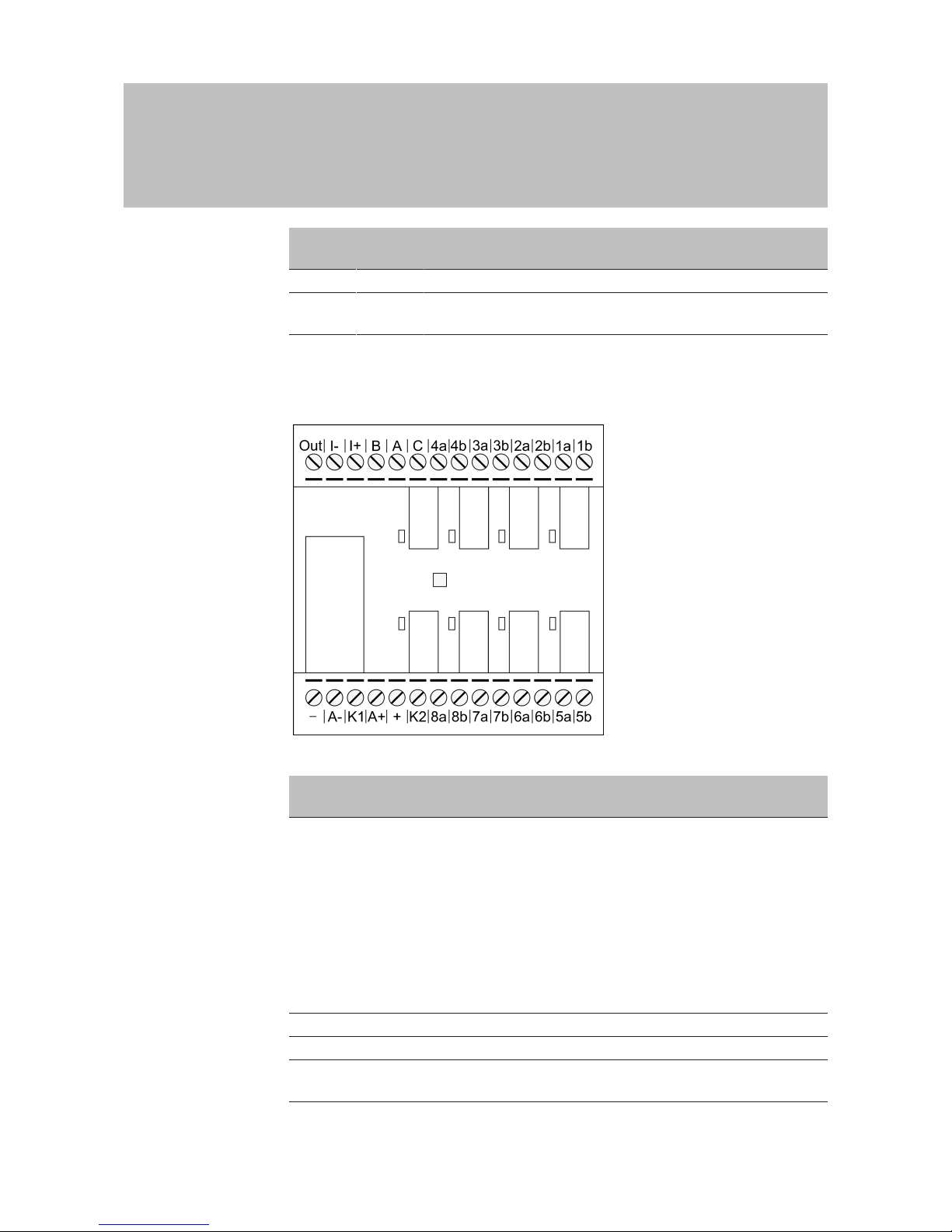
5.3 SmartOutput module
1 5432 9876 10 11 12 13 14
28 222324252627 18192021 151617
No.
Circuit
board
Explanation
1 Out
Brownout detection: Open collector, connected to GND
if supply voltage is sufficient.
This output activates if the supply voltage at VIN falls be-
low 10.0VDC (±0.5VDC). The earth connection is usually
connected to the AUX relay's coil. If the supply voltage
falls at VIN, the AUX relay activates before the other re-
lay contacts activate unchecked due to the decreasing
voltage. When the supply voltage is applied, the output
does not activate until the module has fully initialised
and relay contacts can no longer switch unchecked.
2 I- Isolated digital input. Currently not in use.
3 I+ Isolated digital input. Currently not in use.
4 B
Controller connection: Data Line B; connected to con-
tact for Reader 3.
Page 17

Manual
SmartRelais 3 Advanced
17 / 135
SimonsVoss
5 | Connections
No.
Circuit
board
Explanation
5 A
Controller connection: Data Line A; connected to con-
tact for Reader 3.
6 C
Controller connection: Earth; connected to contact for
Reader 3.
7 4a
Relay 4: Potential-free contact (NC treated as NO in
software); activated depending on authorisations.
8 4b
Relay 4: Potential-free contact (NC treated as NO in
software); activated depending on authorisations.
9 3a
Relay 3: Potential-free contact (NC treated as NO in
software); activated depending on authorisations.
10 3b
Relay 3: Potential-free contact (NC treated as NO in
software); activated depending on authorisations.
11 2a
Relay 2: Potential-free contact (NC treated as NO in
software); activated depending on authorisations.
12 2b
Relay 2: Potential-free contact (NC treated as NO in
software); activated depending on authorisations.
13 1a
Relay 1: Potential-free contact (NC treated as NO in
software); activated depending on authorisations.
14 1b
Relay 1: Potential-free contact (NC treated as NO in
software); activated depending on authorisations.
15 5b
Relay 5: Potential-free contact (NC treated as NO in
software); activated depending on authorisations.
16 5a
Relay 5: Potential-free contact (NC treated as NO in
software); activated depending on authorisations.
17 6b
Relay 6: Potential-free contact (NC treated as NO in
software); activated depending on authorisations.
18 6a
Relay 6: Potential-free contact (NC treated as NO in
software); activated depending on authorisations.
19 7b
Relay 7: Potential-free contact (NC treated as NO in
software); activated depending on authorisations.
20 7a
Relay 7: Potential-free contact (NC treated as NO in
software); activated depending on authorisations.
21 8b
Relay 8: Potential-free contact (NC treated as NO in
software); activated depending on authorisations.
22 8a
Relay 8: Potential-free contact (NC treated as NO in
software); activated depending on authorisations.
23 K2
AUX relay: Potential-free contact (NO). Contact is con-
nected with K1 (number 26) if coil is connected to
power.
Equipped with a detachable bridge to + (number 24) ex
works.
Page 18

Manual
SmartRelais 3 Advanced
18 / 135
SimonsVoss
5 | Connections
No.
Circuit
board
Explanation
24 +
VIN. Connection for power supply.
Equipped with a detachable bridge to K2 (number 23)
ex works.
25 A+
AUX relay: Coil's plus connection. AUX relay activates if
coil is connected to power.
Equipped with a detachable bridge to K1 (number 26)
ex works.
26 K1
AUX relay: Potential-free contact (normally open con-
tact). Contact is connected with K2 (number 23) if coil is
connected to power.
Equipped with a detachable bridge to A+ (number 25)
ex works.
27 A-
AUX relay: Coil's minus connection. AUX relay activates
if coil is connected to power.
28 - GND. Connection for power supply.
Page 19

Manual
SmartRelais 3 Advanced
19 / 135
SimonsVoss
6 | Setting up
6 Setting up
6.1 Unpacking and system test
Scope of delivery
Check to ensure the supply package is complete after receiving it.
Unless agreed otherwise, the supply package contains the following
components:
Controller
Controller 1x
Instruction leaflet 1x
Reader
Reader 1x
Instruction leaflet 1x
SmartOutput module
SmartOutput module 1x
Jumpers (pre-assembled) 2x
Instruction leaflet 1x
System test
You can check the supplied components to ensure they function
correctly before installation and programming. Proceed as follows:
1. Wire the components (see wiring [}55]).
2. Connect the components to the power supply (connect the
controller last).
3. Wait a few seconds until all components are ready for operation.
ð Controller flashes all colours first and then green.
ð Reader flashes all colours first, beeps and then no longer
flashes.
ð Optional SmartOutput module: Relay contacts are open
(indicated by LEDs and a tick-tack sound), then flashes green.
4. Use an identification medium on the reader (empty transponders
or empty DESFIRE card).
ð Reader flashes green twice and beeps.
ð The relay built into controller actuates (Contacts 3, 4 and 5).
Also see
2 Solutions for scenarios [}36]
2 Connecting one or more SmartOutput modules [}63]
6.2 Configuration
You can use the LSM software to programme and configure the controller
and the SREL3 ADV system. Other components do not need to be
programmed.
Page 20
Manual
SmartRelais 3 Advanced
20 / 135
SimonsVoss
6 | Setting up
IMPORTANT
Initial programming via USB
The controller can be addressed via TCP/IP. No IP is featured in storage
mode. That is why initial programming, during which an IP address is issued, must be carried out with a USB connection.
ü Components connected to power.
ü Controller connected to computer with USB cable.
ü Reader connected to the controller (see wiring [}55]).
ü LSM installed and launched as administrator.
ü System requirements met.
1. Create a new G2 locking system.
2. Create a new G2 Smart Relay 3 locking device.
3. Double-click on the SmartRelay 3 entry in the matrix to open the
settings.
4. Select the [IP settings] tab (see Establishing IP settings [}23] for help
on IP settings).
5. Enter an IPv4 address.
6. Enter an IPv4 subnet mask.
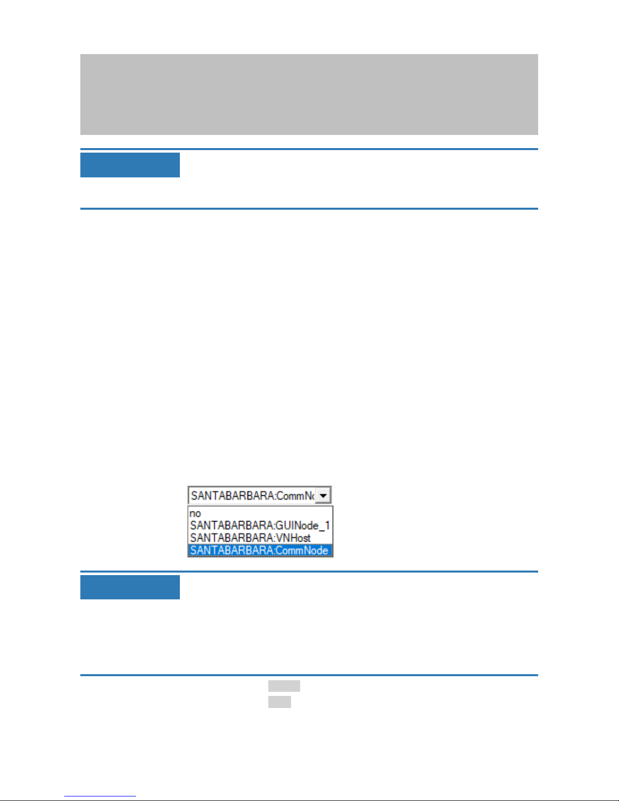
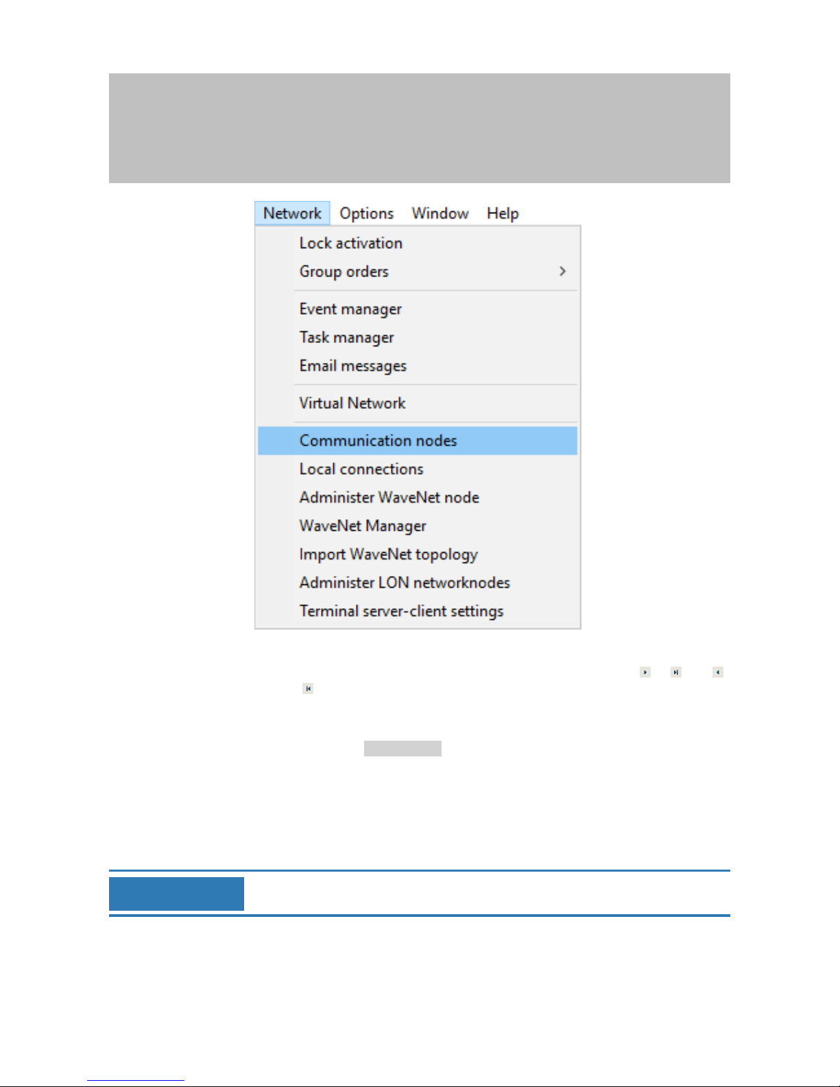
7. Open the Communication nodes drop-down menu.
8. Select a suitable communication node. If you haven't yet created a
communication node for the service, you need to add one first. See
Creating a communication node [}23].
IMPORTANT
Selecting the communication node
If you are using a CommNode server and a VN host server (use of tasks or
events in addition to the virtual network), then choose the CommNode
server entry here.
If you want to use a VN host server (use of the virtual network), then select
the VN host item here.
If you do not wish to use either, then select the GUI node item here.
9. Click on the Apply button.
10. Click on the Exit button.
Page 21
Manual
SmartRelais 3 Advanced
21 / 135
SimonsVoss
6 | Setting up
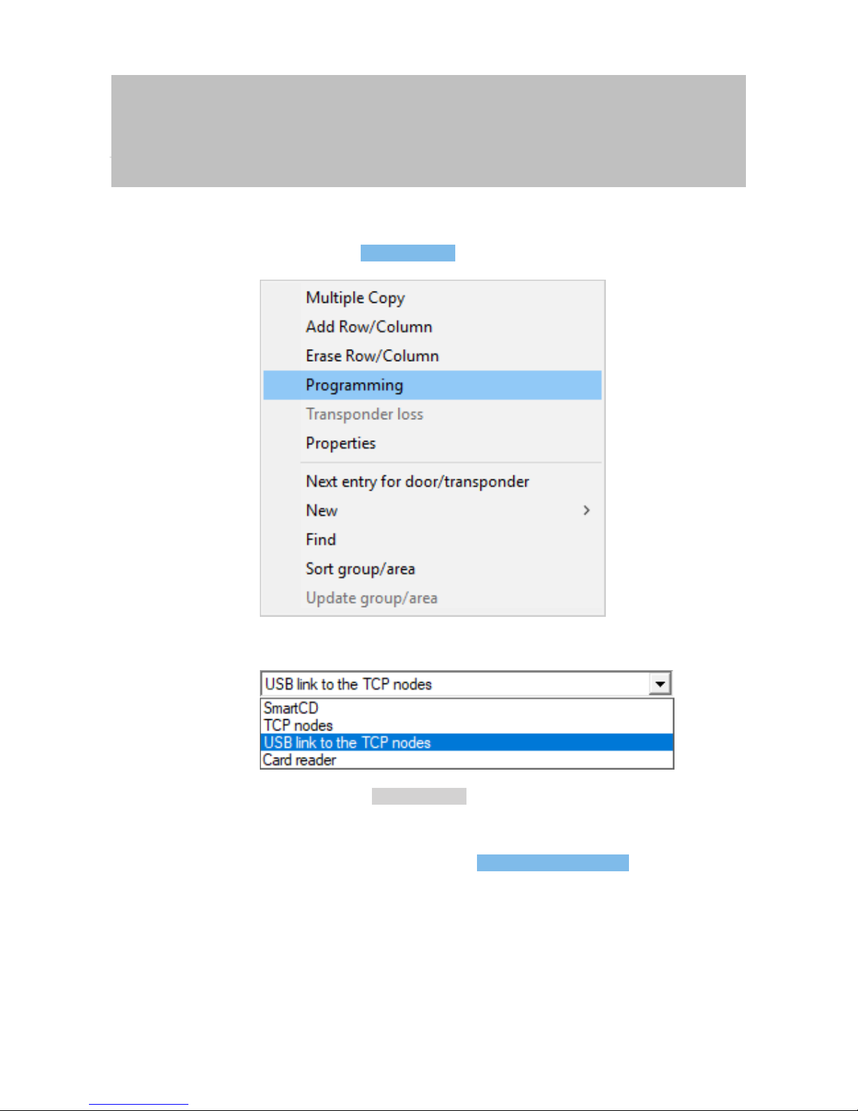
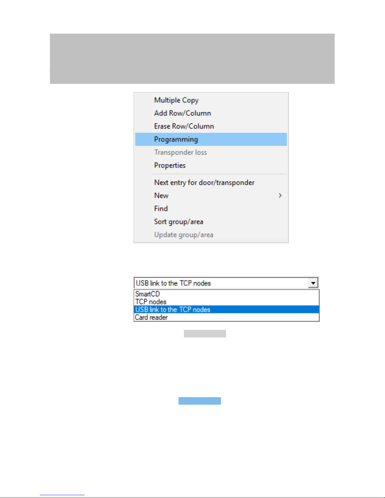
11. Right-click on the SmartRelay 3 entry in the matrix to open the context
menu.
12. Select the Programming item.
13. Select "USB link to the TCP nodes" in the programming window.
14. Click on the Programming button.
ð Programming launches.
15. Wait for programming.
16. Use |Network| to select the Communication nodes item.
Page 22
Manual
SmartRelais 3 Advanced
22 / 135
SimonsVoss
6 | Setting up
17. If you have created more than one communication node, change to
the communication node you have just created. Use the or and
or buttons.
18. Terminate the SimonsVoss VNHost Server or SimonsVoss
CommNode Server service.
19. Click on the Config files button.
20. Open Windows services.
21. Save the service's configuration files locally on your computer.
22. Copy the configuration files saved locally and add them to the
service's installation folder (default: C:\Programme (x86)\SimonsVoss
\VNHost or C:\Program Files (x86)\SimonsVoss\CommNodeSvr_3_4).
IMPORTANT
All three XML files must be copied directly to the installation folder, not to a
sub-folder.
23. Launch the SimonsVoss VNHost Server or SimonsVoss CommNode
Server service again.
Page 23

Manual
SmartRelais 3 Advanced
23 / 135
SimonsVoss
6 | Setting up
IMPORTANT
Click on the Ping button to check whether the service is running and responding. If the service responds, you can continue. If it does not, try to
launch the service again.
24. Click on the Transmit button in LSM.
ð Controller can be reached via network.
25. Terminate the SimonsVoss VNHost Server und SimonsVoss
CommNode Server services.
26. Set up your backup again (see LSM manual).
27. Launch the SimonsVoss VNHost Server and SimonsVoss CommNode
Server services again.
ð Controller can be reached via network and flashes blue.
6.2.1 Establishing IP settings
The SREL3 ADV system controller needs a static IPv4 address to operate
in the network. Ask your IT Department or your network administrator to
assign you a free static IPv4 address and provide you with the following
information:
– IPv4 address
– Associated subnet mask
– Default gateway (only if not all LSM or System 3060 devices are in the
same network)
Alternatively, you can also use DHCP with LSM Version 3.4 SP1 and
above. To do so you need to open the [IP settings] tab and enable the
DHCP activated checkbox.
6.2.2 Creating a communication node
ü LSM launched.
1. Use |Network| to select the Communication nodes item.
2. Enter the communication node name (freely selectable;
recommended: VN host or CommNode).
3. Enter the host name of the computer on which SimonsVoss VNHost
Server has been installed.
IMPORTANT
You can verify the host name as follows:
1. Press the Windows key.
2. Enter cmd.
3. Press the Enter key to confirm.
ð The "[offen]" window will open.
Page 24

Manual
SmartRelais 3 Advanced
24 / 135
SimonsVoss
6 | Setting up
4. Enter hostname.
5. Press the Enter key to confirm.
ð The computer's host name is displayed.
4. Enter the full computer name (fully qualified domain name).
IMPORTANT
It only needs to be entered if the system is working with LSM clients or
database servers in different domains. The FQDN comprises the local computer name and the domain, e.g. COMPUTER.NETWORK.LOCAL. You
can verify the domain yourself:
1. Press the Windows key.
2. Enter cmd.
3. Press the Enter key to confirm.
ð The "[offen]" window will open.
4. Enter echo %userDNSdomain%.
5. Press the Enter key to confirm.
ð The computer's domain is displayed.
5. Click on the Apply button.
ð The communication node is created.
6.3 Programming
Programming does not differ from programming for other locking devices.
The SREL3 ADV system can be programmed using either a USB cable or a
network connection (except initial programming).
USB programming
ü Controller connected to computer with USB cable.
ü Components connected to power.
1. Right-click on the SmartRelay 3 entry in the matrix to open the
context menu.
2. Select the Programming item.
Page 25
Manual
SmartRelais 3 Advanced
25 / 135
SimonsVoss
6 | Setting up
3. Open the Type drop-down menu.
4. Select the "USB link to the TCP nodes" item.
5. Click on the Programming button.
ð Programming launches.
Network programming
ü Controller has already been programmed.
ü Controller connected to computer via network.
ü Components connected to power.
1. Right-click on the SmartRelay 3 entry in the matrix to open the
context menu.
2. Select the Programming item.
Page 26

Manual
SmartRelais 3 Advanced
26 / 135
SimonsVoss
6 | Setting up
3. Open the Type drop-down menu.
4. Select the "TCP nodes" item.
5. Click on the Programming button.
ð Programming launches.
6.3.1 Adding SmartOutput modules
The SREL3 ADV system controller searches for SmartOutput modules after
a power supply has been connected. The controller detects connected
SmartOutput modules when they are supplied electricity.
Programming requires that the number of SmartOutput modules detected
match the number indicated in LSM. You can add SmartOutput modules as
follows.
ü Components wired correctly (see wiring [}55]).
ü Components connected to power.
ü Controller reset (see Resetting the controller [}28]).
Page 27
Manual
SmartRelais 3 Advanced
27 / 135
SimonsVoss
6 | Setting up
1. Double-click on the SmartRelay 3 entry in the matrix to open the
settings.
2. Change to the [Configuration/Data] tab.
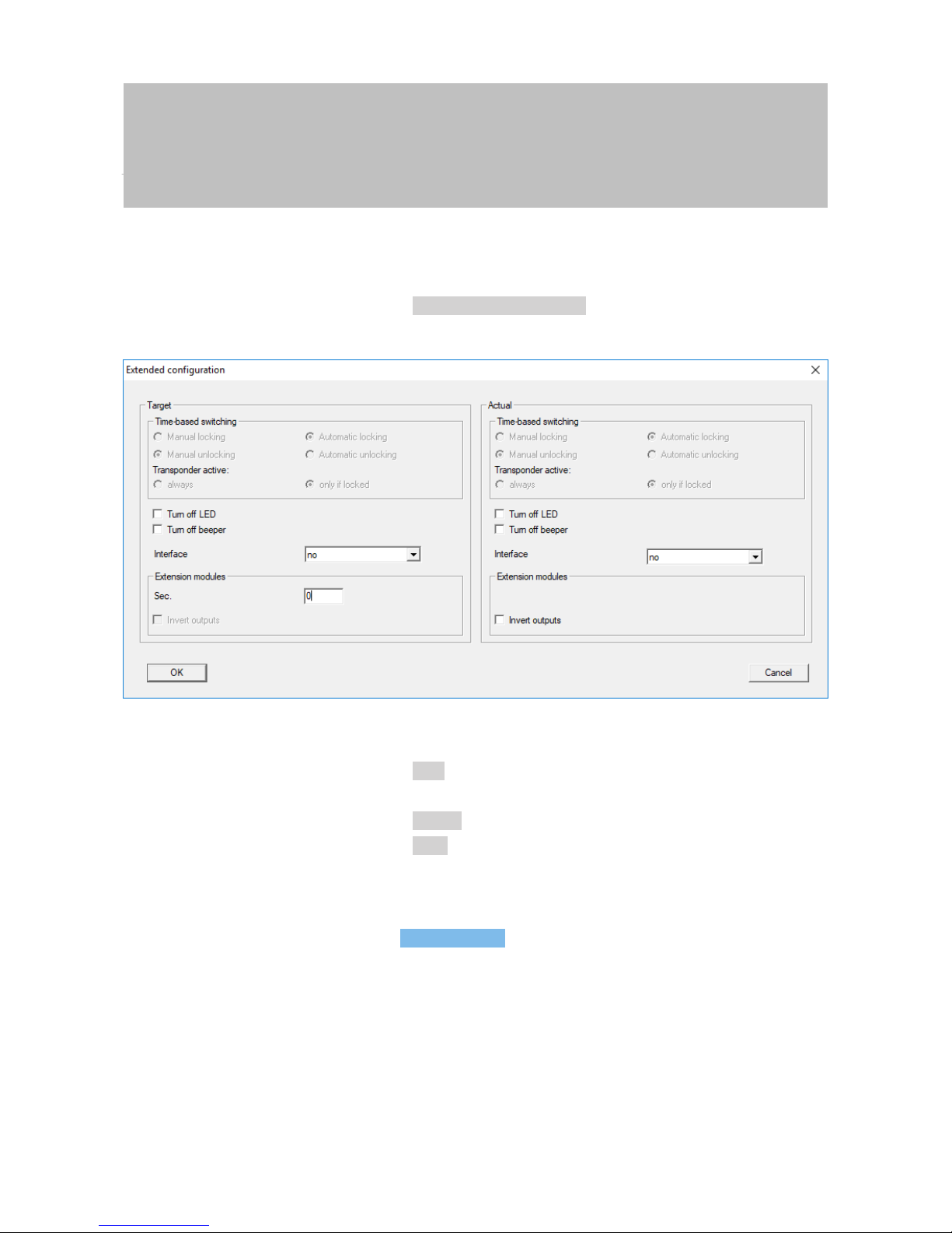
3. Click on the Extended configuration button.
ð "Extended configuration" window will open.
4. Enter the number of connected SmartOutput modules in the
"Extension modules" area.
5. Click on the OK button.
ð Window closes.
6. Click on the Apply button.
7. Click on the Exit button.
ð LSM returns to the matrix.
8. Right-click on the SmartRelay 3 entry in the matrix to open the context
menu.
9. Select the Programming item.
Page 28

Manual
SmartRelais 3 Advanced
28 / 135
SimonsVoss
6 | Setting up
10. Open the Type drop-down menu.
11. Select the "USB link to the TCP nodes" item.
12. Click on the Programming button.
ð Programming launches.
Also see
2 Resetting the controller [}28]
6.3.2 Resetting the controller
You need to reset the controller when changes are made to the connected
components. These include:
– SmartOutput modules added
– SmartOutput modules removed
– Readers added
– Readers removed
Page 29

Manual
SmartRelais 3 Advanced
29 / 135
SimonsVoss
6 | Setting up
A reset deletes the programmed settings.
IMPORTANT
Only the hardware settings and access lists on the controller are reset. The
IP setting remains unchanged
except for the IP settings made during initial programming. The controller
can still be reached using the saved IP address. This means you do not
necessarily need to establish a connection with a USB cable.
6.3.2.1 Resetting controller with a USB cable
The controller can be reset with a USB cable. This option is ideal if the
controller has not yet been installed and can simply be reached physically.
ü Components wired correctly (see wiring [}55]).
ü Components connected to power.
ü Controller connected to computer with USB cable.
1. Mark the entry on the SmartRelay 3 controller in the matrix.
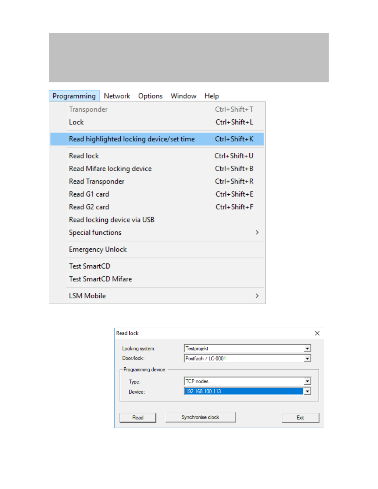
2. Use |Programming| to select the Read highlighted locking device/set
time item.
Page 30

Manual
SmartRelais 3 Advanced
30 / 135
SimonsVoss
6 | Setting up
ð The "Read lock" window will open.
3. Open the Type drop-down menu.
Page 31

Manual
SmartRelais 3 Advanced
31 / 135
SimonsVoss
6 | Setting up
4. Select the "USB link to the TCP nodes" item.
5. Click on the Read button.
ð Locking device is read.
ð The "G2 Smart Relay 3" window will open.
6. Click on the Reset button.
ð The "Reset lock" window will open.
7. Enter the locking system password or apply it from the database.
8. Click on the Reset button.
ð Locking device is reset.
ð Locking device reset.
6.3.2.2 Resetting controller over the network
Alternatively, the controller can also be reset over the network after initial
programming. This option is ideal if the controller has already been installed
and cannot be reached physically.
ü Components wired correctly (see wiring [}55]).
ü Components connected to power.
ü Controller has already been programmed.
ü Controller connected to computer via network.
1. Mark the entry on the SmartRelay 3 controller in the matrix.
2. Use |Programming| to select the Read highlighted locking device/set
time item.
Page 32
Manual
SmartRelais 3 Advanced
32 / 135
SimonsVoss
6 | Setting up
ð The "Read lock" window will open.
3. Open the Type drop-down menu.
Page 33

Manual
SmartRelais 3 Advanced
33 / 135
SimonsVoss
6 | Setting up
4. Select the "TCP nodes" item.
5. Click on the Read button.
ð Locking device is read.
ð The "G2 Smart Relay 3" window will open.
6. Click on the Reset button.
ð The "Reset lock" window will open.
7. Enter the locking system password or apply it from the database.
8. Click on the Reset button.
ð Locking device is reset.
ð Locking device reset.
6.4 Application examples
This section explains the interplay between components in the SREL3 ADV
system and shows a few use cases as an example.
ATTENTION
Overload in a fitted relay
The permitted current and permitted voltage must not be exceeded.
1. Observe the specifications (see Properties [}121]).
2. Ensure that the load on the relay is not plugged into a different element
or has been increased in some other way.
6.4.1 Basic principle
The SmartRelay 3 system always comprises of a controller, at least one
reader and optional SmartOutput modules.
The reader is not able to evaluate detected identification media for security
reasons. The communication between the reader and controller is secured.
The reader can thus also be installed in unsecured areas without any
problems.
Page 34

Manual
SmartRelais 3 Advanced
34 / 135
SimonsVoss
6 | Setting up
6.4.2 Gateway function
The SREL3 ADV system can also be used as a gateway for the virtual
network, no matter whether a relay contact is used or not. Any identification
medium which is logged onto one of up to three readers is updated. In
doing so, a difference must be made between network-dependent and
network-independent functions.
Network-independent
– Loading time budgets: Users are able to re-upload their time
budgets at any time without the network.
– Automatic blacklist distribution: IDs which have already been
flagged for blocking in the controller are also distributed in the
virtual network without a network connection.
Partially network-independent
When the network connection is re-established, the controller
transmits information which was collected during the outage:
– Feedback signals from blacklist broadcasts: Locking devices
which have received authorisation changes for transponders emit
a feedback signal. This feedback signal is transmitted to the
controller via the virtual network.
– Battery warnings: Locking devices which have low batteries
transmit a battery warning to the controller via the identification
media in the virtual network.
– Physical access lists: The smart card physical access list are read
and saved by the controller independently of the network.
Network-dependent
If there is a network connection, other virtual network functions are
available on the gateway:
– Issuing of individual authorisations: When an identification
medium has logged on, the controller retrieves the latest
authorisation information for the transponder concerned from the
VN host server via the network. The authorisation changes are
updated on the transponder via the reader if necessary.
– Configuration changes: The controller retrieves configuration
changes to identification media, such as a time group change,
from the VN host server.
– Issuing of individual blacklist IDs: Up to two IDs to be blocked can
also be added to selected identification media in the virtual
network. To do so, the controller retrieves the IDs to be blocked
from the VN host server when such an identification medium logs
on.
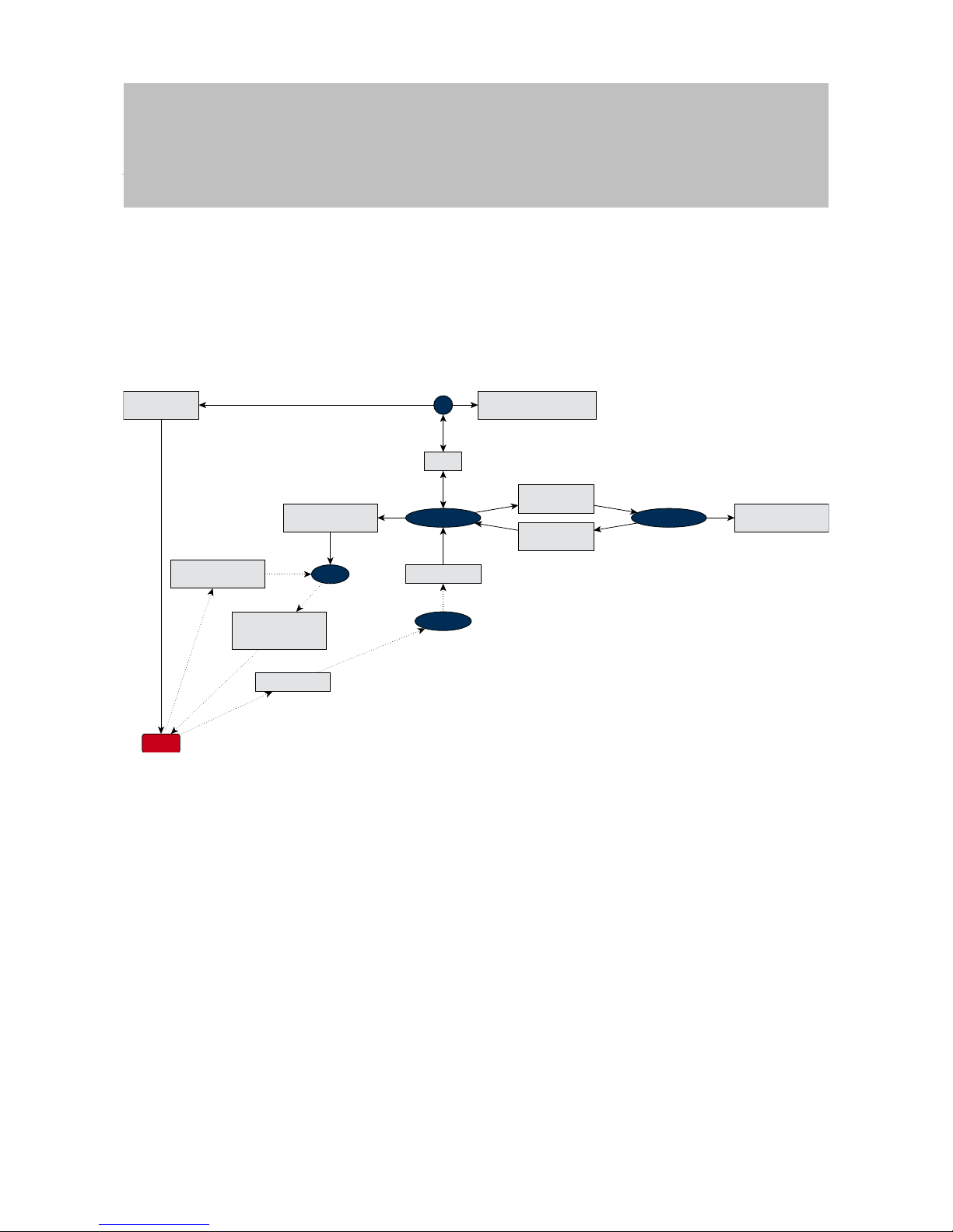
6.4.3 General overview
Controller communication with LSM
The controller does not communicate directly with the database. A
distinction must be made with communication between the controller
and the database:
Page 35
Manual
SmartRelais 3 Advanced
35 / 135
SimonsVoss
6 | Setting up
– Use in the virtual network: The controller is programmed by LSM
and also requests information itself from the VN host using the
detected ID medium.
– Use without virtual network: The controller does not request
information itself on its own. Changes need to be programmed.
Events on the controller such as a pressed button are transmitted to
the LSM database via the CommNode.
Shows interface to
control and edit
Programmes and
updates
Requests updates for
detected ID medium
Supplies information
on detected ID medium
on request
Transmits events
Adds changes to
identification media
GUI
Edits
LSM database
Saves events
in LSM database
CommNode
Receives information
about locking system
Checks statuses
in the database
SmartSurveil
Shows status
changes on the monitor
Controller
VN host
Controller communication with the components
A user can log onto up to three readers with an ID medium. The
reader forwards encrypted information to the controller, which is
located within a protected area. The controller evaluates the
information:
– Use in the virtual network: The controller verifies the information
with the VN host.
– Use without virtual network: The controller draws on information
stored locally when it was last programmed.
If the authorisation was checked successfully, the controller can:
– Actuate an internal relay, which can then be used to activate
external devices.
– Transmit a recognised identification medium to an external device
via the serial interface.
– Switch one or several outputs via an optional SmartOutput module
chain.
Page 36

Manual
SmartRelais 3 Advanced
36 / 135
SimonsVoss
6 | Setting up
The controller can also respond to a digital entry and, consequently, a
connected button or similar as an alternative to successful
identification.
Reader 1
(obligatory)
Reader 2
(optional)
Reader 3
(optional)
As Reader 1
As Reader 1
Forwards identification
media
Supplies electricity where required
Reads access lists
Updates time budgets
Writes authorisation changes
Emits signals (opt., aud.)
Controller
Transmits commands to actuate
SmartOutput module
(optional)
Parallel
circuit
Connection to external
devices, e.g. electric strikes
Connection to external
devices, e.g. electric strikes
Internal relay
Digital outputs
Digital inputs
Connection to external
devices, e.g. buttons
Push-to-open on 3
Transmits commands to external
devices. Available protocols
see specifications
Connection to external
devices, e.g. electric strikes
SmartOutput module
(optional)
6.4.4 Solutions for scenarios
The SREL3 ADV system is the time-tested solution for a large number of
use cases. This section presents a few of them and shows how the SREL3
ADV system is used. The wiring is basically always as described in terms of
electrics (see wiring [}55]). However, line lengths, cable types and wiring
installation options vary, depending on the use case.
IMPORTANT
Protected areas are areas which can only be accessed with an authorised
identification media or are secured against unauthorised access in some
other way.
DANGER
Risk of injury due to incorrect programming
The SREL3 ADV system is not suitable to replace existing security installations.
1. Ensure that the SREL3 ADV system is used as an additional securing
measure only.
2. Do not replace existing security installations with the SREL3 ADV
system.
Page 37

Manual
SmartRelais 3 Advanced
37 / 135
SimonsVoss
6 | Setting up
In the following section, the term unprotected area refers to an area or
place which anyone can access. The protected area refers to an area or
place which only persons who have previously identified themselves at
least once as access-authorised with an authorised identification media
may access.
6.4.4.1 Doors
The SREL3 ADV system can be used to secure doors.
Door with a reader and
a button
Button in the
protected
area
Elec. connection
to the button
Elec. connection to electric
strike on sliding door, for example
Encrypted
connection
to the reader
Reader in
the unprotected
area
External
power supply unit
Ethernet connection to LSM
Optional PoE instead of PSU
Controller with relay output
in the protected area
Serial connection
to third-party systems
In this use case, the controller is installed in a protected area, such as
the building interior. An external reader is mounted on the
unprotected side of the door and can read identification media.
No-one can manipulate the data since communication is secured
from the reader to the controller and to LSM. When the data reach the
controller, the controller evaluates them. If there is a virtual network
and connection to LSM (Ethernet), the latest information is retrieved
using the identification medium; if not, the system used the last status
saved internally. Depending on the result of the evaluation, the
controller triggers the required action, such as actuate a relay.
Page 38

Manual
SmartRelais 3 Advanced
38 / 135
SimonsVoss
6 | Setting up
The controller also features a pre-configured, non-reprogrammable
push-to-open function. The relay actuates if the relevant contacts
(see Controller [}14]) are interconnected with one another. The relay
integrated into the controller can be operated with an authorised
identification medium or by connecting the relevant contacts. One or
more buttons can be installed on the contacts. Users can press these
buttons instead of using an identification medium in a secured area.
This improves user convenience without losing control over the door
status.
If the reader needs to be protected against vandalism, sabotage or
the effects of the weather, a protective housing can be fitted to the
reader (SREL2.COVER1).
Building entrance doors are a special case:
– All users need to pass through one of the building entrance doors
on a daily basis.
– Building entrance doors are exposed to the weather on one side.
– Building entrance doors are in an unsecured area on one side.
– It must also be possible to open building entrance doors without
an identification medium in an emergency at times.
If a virtual network is used, building entrance doors are ideal for use
as a gateway. The building entrance is a door which many users pass
through on a daily basis. This means that each identification medium
used here is verified on the reader and, consequently, in the LSM
database via the controller. Authorisation changes, IDs to be blocked
and time budgets are thus efficiently managed.
Access events can be forwarded to a third-party system via the serial
interface.
The controller can be powered either via an external power supply
unit or via the network line. The controller, in turn, can power the
reader. If the voltage drop is too great, the reader can also be
supplied by an external power supply unit (see External power supply
[}57]).
See Connecting one or more readers [}55] and Connecting one or
more buttons [}61] on wiring.
Use with two buttons
Page 39
Manual
SmartRelais 3 Advanced
39 / 135
SimonsVoss
6 | Setting up
Button in the
protected
area
Button in the
protected area
Elec. connection
to the button
Controller with relay output
in the protected area
Elec. connection to electric
strike (e.g. sliding door)
External
power supply unit
Ethernet connection to LSM
Optional PoE instead of PSU
Elec. connection
to the button
ATTENTION
No check on authorisation
Any person who has physical access can operate the relay by using the
two buttons.
1. Ensure that no unauthorised persons can access this locking device.
There is no longer a need to use an identification medium. Users only need
to press a button to operate the relay (and open the sliding door in this
example). Compared to a purely electrical connection, this approach brings
the advantage of providing an overview when the relay was actuated and
what its current status is (see SmartSurveil [}101]).
The relay is not protected against unauthorised operation. This type of
connection is thus only suitable for installing in areas which are already
secured.
See Connecting one or more buttons [}61] on wiring.
Page 40
Manual
SmartRelais 3 Advanced
40 / 135
SimonsVoss
6 | Setting up
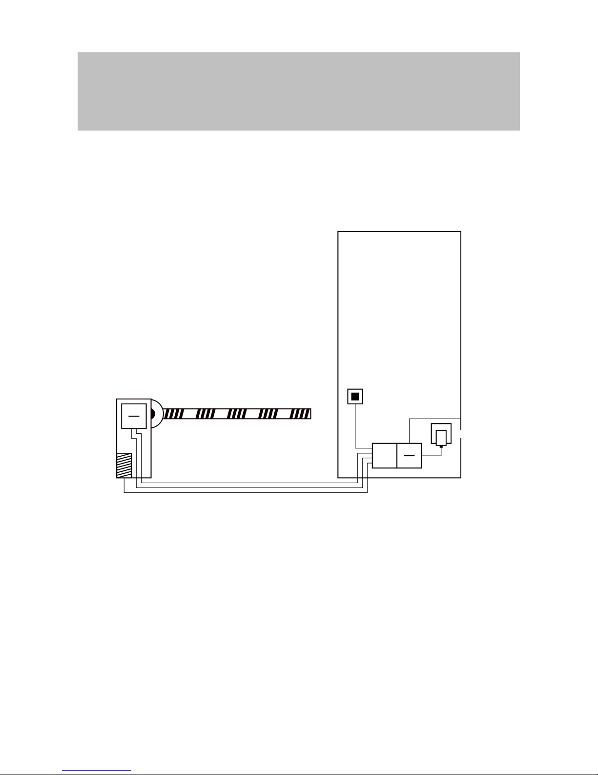
6.4.4.2 Entrance barrier
People who want to drive into a segregated area, such as a company car
park, need to pass through an entrance barrier. Not everyone can have an
authorised identification medium as this would involve considerable
organisation. An entrance barrier is also normally installed outdoors and is
thus exposed to the weather, vandalism and sabotage.
Button in the
protected
area
Ethernet connection to LSM
Optional PoE instead of PSU
Elec. connection
to the controller
Reader in the
unprotected area
Encrypted connection
to the controller
Elec. connection
to the barrier drive
Barrier
drive
External PSU
The SREL3 ADV system offers an intelligent solution for such situations.
The controller is installed in a protected area, such as the engineering
room. A reader needs to be installed close to the barrier. There are two
solutions:
– The reader is fitted into the barrier housing. This variant discreetly
blends in. It provides excellent protection against the weather,
vandalism and sabotage.
– The reader is fitted on the barrier housing. This variant is visible on the
outside and makes it easier for users to place their identification
medium onto the reader. The read range is better compared to a reader
fitted inside the barrier housing. The protective housing
(SREL2.COVER1) ensures protection against the weather, vandalism
and sabotage.
Page 41

Manual
SmartRelais 3 Advanced
41 / 135
SimonsVoss
6 | Setting up
The user can use their identification media to check authorisation while in
the car. If the user does not have an identification medium, but is expected,
they can still announce their arrival, using an intercom, for example.
Another person who is in the protected area can then let the user in by
pressing the connected button. The button can be installed in a gatehouse,
for example, which only allows external customers to enter during business
hours while users with identification media can come in at any time.
No-one can manipulate the data since communication is secured from the
reader to the controller and to LSM. When the data reach the controller, the
controller evaluates them. If there is a virtual network and connection to
LSM (Ethernet), the latest information is retrieved using the identification
medium; if not, the system used the last status saved internally. Depending
on the result of the evaluation, the controller triggers the required action,
such as actuate a relay.
If a virtual network is used, the system is ideal for use as a gateway. The
barrier is a locking device which is very heavily used. This means that
many identification media are already synchronised with the LSM database
before they reach the building entrance. As a result, there is less load on
the gateway on the building door. In this case, the reader should be
installed where it is visible for users to ensure that they can hear or see the
reader feedback signals.
The controller can be powered either via an external power supply unit or
via the network line. The controller, in turn, can power the reader. If the
voltage drop is too great, the reader can also be supplied by an external
power supply unit (see External power supply [}57]).
Since a feed line needs to be installed for the barrier motor, the power
supply for the reader can be easily connected to this line. Power is reliably
supplied to the reader with a power supply unit, so the reader is not
affected by any voltage drops due to line length.
See Connecting one or more readers [}55] and Connecting one or more
buttons [}61] on wiring.
6.4.4.3 Lift
A lift is a special case. Lift cabs are usually connected to their environment
through a trailing cable. However, the number of lines within the trailing
cable is limited. The SREL3 ADV system requires a varying large number
of lines, depending on the configuration.
It is highly recommended to use one or several SmartOutput modules in a
lift to provide sufficient relay contacts. We also need to consider that the
controller should be mounted on top of the lift cab or a network connection
must be laid through the trailing cable.
If one or several SmartOutput modules are used, effective access
management can be implemented in the lift itself with authorisation required
for buttons for specific floors.
Page 42

Manual
SmartRelais 3 Advanced
42 / 135
SimonsVoss
6 | Setting up
The reader and the SmartOutput module are installed in the lift. Users
identify themselves with their identification medium in the lift.
No-one can manipulate the data since communication is secured from the
reader to the controller and to LSM. When the data reach the controller, the
controller evaluates them. If there is a virtual network and connection to
LSM (Ethernet), the latest information is retrieved using the identification
medium; if not, the system used the last status saved internally. Depending
on the result of the evaluation, the controller triggers the required action,
such as actuate a relay.
ATTENTION
Interferences in the trailing cable
Lines in the trailing cable through which data is to be transmitted must be
shielded (also see Recommended cable types [}127]).
Power supply from cab
This connection option requires the fewest free lines in the trailing cable
and avoids voltage drops due to excessively long lines. The controller can
be installed outside the lift where it is protected in a place, such as the
engineering room.
The reader is not powered via the controller. Instead, it is connected to the
existing power supply in the lift cab, which provides electricity for lighting,
doors and other elements. The voltage may need to be converted with a
power supply unit, so that it is within the specified voltage range for the
SmartOutput module and reader (see Properties [}121]). The voltages
supplied to the individual components do not need to be identical. It is thus
possible to operate the controller with 12V while the reader in the lift is
operated with 24V.
Common earth connection
In this specific case, four lines are also needed to supply power to the
cab.
Line Use
1 Controller – reader: Data line A
2 Controller – reader: Data line B
3 Controller – SmartOutput module: Data line A
4 Controller – SmartOutput module: Data line B
DANGER
Electric shock due to mains voltage
An electric shock may be caused when connecting the non-hazardous
earth (low voltage) to a conductor which carries the mains voltage.
1. Only use conductors with a low-voltage potential (<42V) as a common
earth cable!
2. Protect live cables, so people do not touch them accidentally!
Page 43
Manual
SmartRelais 3 Advanced
43 / 135
SimonsVoss
6 | Setting up
SmartOutput module
in cab
Reader in
the unprotected area
Lift
electronics
Voltage converter
Ethernet connection to LSM
External PSU
Controller in the
protected area
Power
supply for
lift cab
Trailing cable
IMPORTANT
A common earth connection is required between the controller, reader and
SmartOutput modules. The cab power supply earth connection can be used
to save on lines in the trailing cable. The controller's earth connection
needs to be connected to the cab power supply earth connection in this
case.
See Common earth with power supply [}69] on wiring.
Separate earth connection
If a common earth cable cannot be used for the cab power supply
and the components, an additional line needs to be assigned in the
trailing cable. In this specific case, five lines are also needed to
supply power to the cab.
Page 44

Manual
SmartRelais 3 Advanced
44 / 135
SimonsVoss
6 | Setting up
Line Use
1
Earth connection between controller, reader
and SmartOutput modules
2 Controller – reader: Data line A
3 Controller – reader: Data line B
4 Controller – SmartOutput module: Data line A
5 Controller – SmartOutput module: Data line B
Reader in
the unprotected area
Lift
electronics
Voltage converter
Trailing cable
SmartOutput module
in cab
Controller in the
protected area
Power
supply for
lift cab
External PSU
Ethernet connection to LSM
Optional PoE instead of PSU
The earth cables in the power supplies are separated from the
common earth cable in this case.
See Common earth with SREL3 components [}70] and Connecting
one or more readers [}55] on wiring.
Page 45

Manual
SmartRelais 3 Advanced
45 / 135
SimonsVoss
6 | Setting up
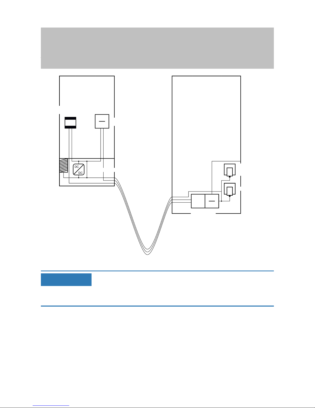
Power supply via trailing cable
This connection option does not access existing lift electronics. This
means the lift electronics remain intact and a new inspection may be
avoided.
The components are powered via the trailing cable only. The required
power supply unit is at the other end of the trailing cable. Depending
on the length of the trailing cable, a possible voltage drop must be
taken into account to meet specifications (see Properties [}121]).
ATTENTION
Malfunctions due to voltage drop
The physically induced voltage drop in the trailing cable may cause low
voltages in power supplies which come from outside the cab.
1. Take the cable length into account.
2. Switch to a version with power supply in the cab if necessary (see
Common earth with power supply [}69] and Common earth with
SREL3 components [}70]).
3. Make the cable gauge larger by merging lines in the trailing cable.
Insert: Reader with
SmartOutput module
and common supply
The SmartOutput module requires its own power supply. The reader
can also be connected to this power supply. Six free lines are
required in addition to the existing lines.
Line Use
1
Earth connection between controller, reader
and SmartOutput modules
2 Positive terminal on the power supply
3 Controller – reader Data line A
4 Controller – reader Data line B
5 Controller – SmartOutput module: Data line A
6 Controller – SmartOutput module: Data line B
Page 46

Manual
SmartRelais 3 Advanced
46 / 135
SimonsVoss
6 | Setting up
SmartOutput module
in cab
Lift electronics
Reader in
the unprotected area
Ethernet connection to LSM
Optional PoE instead of PSU
Power supply for
lift cab
External power supply
unit
Controller in the
protected area
Trailing cable
External power supply
unit for SOM and reader
IMPORTANT
The power supply unit for the reader and the SmartOutput modules can be
omitted if the controller power supply unit can deliver sufficient electricity
and supply a voltage of 12VDC.
See Power supply through trailing cable [}72] and Connecting one or
more readers [}55] on wiring.
Insert: Reader without
SmartOutput module
The controller powers the reader. An additional power supply unit is
not required. Four free lines are required in addition to the existing
lines.
Page 47

Manual
SmartRelais 3 Advanced
47 / 135
SimonsVoss
6 | Setting up
Line Use
1
Earth connection between controller and
reader
2 Positive terminal on the power supply
3 Controller – reader: Data line A
4 Controller – reader Data line B
Reader in
the unprotected area
Lift
electronics
Trailing cable
Controller in the
protected area
External PSU
Power
supply for
lift cab
Ethernet connection to LSM
Optional PoE instead of PSU
See Power supply through the controller [}74] on wiring.
Insert: Controller-fed
reader with SmartOutput module
The controller powers the reader. Connected SmartOutput modules
are powered via an additional power supply unit at the other end of
the trailing cable. Nine free lines are required in the trailing cable in
addition to the existing lines.
The reader and its connection to the controller do not need to be
removed. This means it is possible to retrofit SmartOutput modules to
an existing connection.
Page 48

Manual
SmartRelais 3 Advanced
48 / 135
SimonsVoss
6 | Setting up
Line Use
1
Earth connection between SmartOutput mod-
ule and power supply unit
2
Positive terminal for power supply between
SmartOutput module and power supply unit
3
Earth connection between controller and
reader
4
Positive terminal for power supply between
controller and reader
5 Controller – SmartOutput module: Data line A
6 Controller – SmartOutput module: Data line B
7
Controller – SmartOutput module: Data line
earth connection
8 Controller – reader Data line A
9 Controller – reader Data line B
Page 49

Manual
SmartRelais 3 Advanced
49 / 135
SimonsVoss
6 | Setting up
SmartOutput module
in cab
Reader in
the unprotected area
Lift
electronics
Trailing cable
Ethernet connection to LSM
Optional PoE instead of PSU
External power supply
unit for SOM
Power
supply for
lift cab
Controller in the
protected area
External PSU
See Controller-fed reader with SmartOutput modules [}75] and
Connecting one or more readers [}55] on wiring.
Also see
2 Power supply from cab [}42]
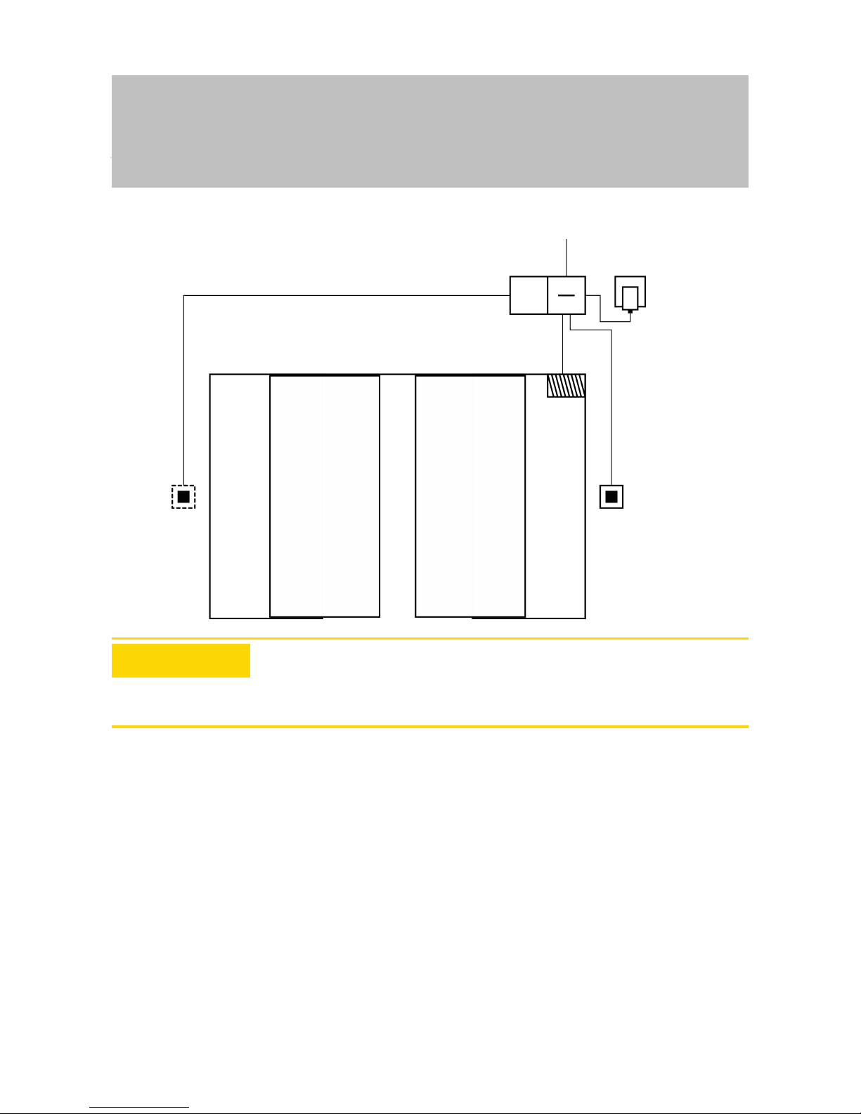
6.4.4.4 Safe deposit boxes
Safe deposit box systems are used by a variety of users. Only authorised
persons should be able to open their designated deposit boxes. Deposit
box systems are not always installed in areas protected from the weather.
Suppliers, deliverers and a selected group of people should be able to
access all deposit boxes. Some people may need to be able to open
several deposit boxes.
Page 50

Manual
SmartRelais 3 Advanced
50 / 135
SimonsVoss
6 | Setting up
SOM in
deposit box
system
Reader in
the unprotected area
Parallel connection
Controller in the
protected area
External PSU
PSU for
SmartOutput module
Ethernet connection to LSM
Optional PoE instead of PSU
SOM in
deposit box
system
Parallel connection
Encrypted
connection
to the controller
The existing connections to open the locking system can be actuated with
the SmartOutput modules, no matter whether a direct or alternating current
is used. The SmartOutput modules are connected in parallel for this
purpose. The address can be configured individually on each SmartOutput
module. This allows up to fifteen SmartOutput modules with eight outputs
each to be connected to the system (except the last module, which
supports only four relays). The deposit box is opened as soon as the
controller receives an opening command to the corresponding relay.
Identification media can be authorised for individual relays and,
consequently, individual deposit boxes in LSM. However, it is also possible
to group identification media together, for a department, for example, and
authorise this group to use a single relay, in a departmental deposit box.
Identification medium verification means you can trace which of the group's
identification media has operated the relay (and taken documents, for
example). If individual persons are supposed to be able to open a number
of deposit boxes, relays can be grouped – in different trust levels, for
example. The group of authorised persons becomes smaller as the trust
level increases.
There are two options for installing the reader:
– The reader is installed in an existing housing – in an intercom housing,
for example. This variant is hidden from view and offers effective
protection against the weather, vandalism and sabotage.
Page 51

Manual
SmartRelais 3 Advanced
51 / 135
SimonsVoss
6 | Setting up
– The reader is fitted on the wall. This variant is visible on the outside and
makes it easier for users to place their identification medium onto the
reader. The read range is better compared to a reader fitted inside the
housing. If the reader is installed outdoors, protection against the
weather, vandalism and sabotage can be assured with the protective
housing (SREL2.COVER1).
A master identification medium can be created for emergencies. This can
be used to open several or all boxes at the same time.
The controller can be powered either via an external power supply unit or
via the network line. The controller, in turn, can power the reader. If the
voltage drop is too great, the reader can also be supplied by an external
power supply unit (see External power supply [}57]).
See Connecting one or more readers [}55] and Connecting one or more
SmartOutput modules [}63] on wiring.
Also see
2 Connecting one or more buttons [}61]
6.4.4.5 Machine safety
Machines can pose significant hazards:
– Cuts
– Burns
– Electric shocks
– Laser radiation
– Crushing
For safety reasons, only qualified people should therefore be allowed to
operate hazardous machines. Unauthorised persons must not be able to
put hazardous machines into operation.
An option to switch off the machine without authorised identification media
further increases operational safety.
DANGER
Risk of injury due to incorrect programming
The SREL3 ADV system is not suitable as a sole disconnecting device. A
contactor activated via the controller must never be the only means to
switch off a machine.
1. Use the SREL3 ADV system as an additional disconnecting device only,
not as the sole one.
2. Use the actuated contactor in a series circuit with the machine's
emergency stop switch only.
Page 52

Manual
SmartRelais 3 Advanced
52 / 135
SimonsVoss
6 | Setting up
Safety switch
(zero voltage switch)
Reader in
the unprotected
area
External PSU
Ethernet connection to LSM
Optional PoE instead of PSU
Controller in the
protected area
Encrypted connection
to the controller
Elec. connection
to the relay in the controller
The SREL3 ADV system provides effective protection to prevent
unauthorised persons from putting dangerous machines into operation and
injuring themselves. The reader is fitted to the machine requiring protection
and connected to the controller. The relay in the controller does not switch
until an authorised identification medium has been activated on the reader,
thus unblocking the power supply to the machine by switching the
contactor. Only then can the machine be switched on at the safety switch.
There are two options for installing the reader:
– The reader is fitted into the machine housing. This variant is hidden
from view and offers effective protection against the weather, dirt, fluids
and mechanical impacts, depending on the machine housing.
– The reader is fitted on or next to the machine housing. This variant is
visible on the outside and makes it easier for users to place their
identification medium onto the reader. The read range is better
compared to a reader fitted inside a (metal) housing. The protective
housing (SREL2.COVER1) ensures protection against the weather, dirt,
liquids and slight mechanical impacts.
No-one can manipulate the data since communication is secured from the
reader to the controller and to LSM. When the data reach the controller, the
controller evaluates them. If there is a virtual network and connection to
LSM (Ethernet), the latest information is retrieved using the identification
Page 53

Manual
SmartRelais 3 Advanced
53 / 135
SimonsVoss
6 | Setting up
medium; if not, the system used the last status saved internally. Depending
on the result of the evaluation, the controller triggers the required action,
such as actuate a relay.
The machine can only be put into operation if an identification medium is
used on the reader. In the event of damage, the access list (for ZK variants
only) will allow management to identify exactly who operated the machine
last and take appropriate measures.
The controller can be powered either via an external power supply unit or
via the network line. The controller, in turn, can power the reader. If the
voltage drop is too great, the reader can also be supplied by an external
power supply unit (see External power supply [}57]).
See Connecting one or more readers [}55] on wiring.
Also see
2 Connecting one or more buttons [}61]
6.4.4.6 Underground car park entrance
An underground car park entrance is a similar situation to an entrance
barrier (see Entrance barrier [}40]) since anyone who wants to enter an
underground garage from the outside must use the entrance. Some of
these people, such as business customers, do not have an identification
medium. The exterior part is also not exposed to the weather, vandalism
and sabotage. The main difference is that an underground car park can be
secured with elements such as roll-up doors to ensure unauthorised
persons cannot walk through the entrance.
The underground car park interior can thus be regarded as a protected
area.
Page 54

Manual
SmartRelais 3 Advanced
54 / 135
SimonsVoss
6 | Setting up
Door drive
Reader in
the unprotected area
Encrypted connection
to the controller
External PSU
Elec. connection
to the controller
Elec. connection to the
relay in the controller
Controller in the
protected area
Button in the
protected area
Elec. connection
to the controller
The SREL3 ADV system can be used to provide a convenient underground
car park control. As with all other use cases, the controller is installed in a
protected area, such as the engineering room. A reader is also needed in
front of the roll-up door, close to the entrance:
– The reader is installed in a suitable position in an existing housing – in
an existing intercom housing, for example. This variant is inconspicuous
and offers effective protection against the weather, vandalism and
sabotage.
– The reader is fitted on the wall. This variant is visible on the outside and
makes it easier for users to place their identification medium onto the
reader. The read range is better compared to a reader fitted inside an
existing housing. The protective housing (SREL2.COVER1) ensures
protection against the weather, vandalism and sabotage.
The user can use their identification media to check authorisation while in
the car. If the user does not have an identification medium, but is expected,
they can still announce their arrival, using an intercom, for example.
Another person who is in the protected area can then let the user in by
pressing the connected button. The button can be installed in a gatehouse,
for example, which only allows external customers to enter during business
hours while users with identification media can come in at any time.
Page 55

Manual
SmartRelais 3 Advanced
55 / 135
SimonsVoss
6 | Setting up
Users who wish to leave the underground car park are within a protected
area. Consequently, there is no need to re-verify authorisation for the door.
Greater convenience is provided by connecting one button in a parallel
circuit with another button (in the gatehouse) and positioning it near to the
exit within the protected area.
No-one can manipulate the data since communication is secured from the
reader to the controller and to LSM. When the data reach the controller, the
controller evaluates them. If there is a virtual network and connection to
LSM (Ethernet), the latest information is retrieved using the identification
medium; if not, the system used the last status saved internally. Depending
on the result of the evaluation, the controller triggers the required action,
such as actuate a relay.
If a virtual network is used, the system is ideal for use as a gateway. The
underground car park entrance features a locking device which is heavily
used. This means that each identification medium used here is verified on
the reader and, consequently, in the LSM database via the controller.
Authorisation changes, IDs to be blocked and time budgets are thus
efficiently managed.
The controller can be powered either via an external power supply unit or
via the network line. The controller, in turn, can power the reader. If the
voltage drop is too great, the reader can also be supplied by an external
power supply unit (see External power supply [}57]).
ATTENTION
Manipulation of unprotected electrical connections
Unprotected electrical connections can be short-circuited or manipulated in
another way.
1. Install electrical connections from buttons to the controller within
protected areas only.
2. Install electrical connections from the controller to the contactor or the
device being activated within protected areas only.
See Connecting one or more readers [}55] and Connecting one or more
buttons [}61] on wiring.
6.4.5 wiring
6.4.5.1 Connecting one or more readers
IMPORTANT
If you use one or two card readers, you may wire them either to the first,
second or third connection. If you wish to connect SmartOutput modules,
you may only use the connection on the third reader.
Page 56

Manual
SmartRelais 3 Advanced
56 / 135
SimonsVoss
6 | Setting up
Power supply through the controller
The readers (up to three readers per controller) are connected to the
controller at the designated points. This type of wiring is the simplest type
of connection between readers and controllers. The controller loops the
power supply through to the connections for the readers, which can then be
operated without an additional power supply unit.
ATTENTION
Malfunctions due to voltage drop
A voltage drop occurs in the lines between the controller and reader. If the
voltage drop is too great, the voltage on the reader is no longer sufficient
for reliable operation.
1. Observe the cable length specifications (see Properties [}121]).
2. Use an external power supply unit to power readers in cases of doubt
(see External power supply [}57]).
Use this configuration to verify that the components which they contain
function correctly.
Page 57

Manual
SmartRelais 3 Advanced
57 / 135
SimonsVoss
6 | Setting up
-
+
1(1)
<
1(2)
2(1)
<
2(2)
+1
-
B1
A1
+2
-
B2
A2
+3
-
B3
A3
O4
O3
O2
O1
O+
I+
-
I1
I2
I3
A
B
-
+
-
A
B
-
+
-
A
B
-
+
-
+
-
N
L
Controller
Power
supply unit
Reader
Reader
Reader
External power supply
The readers (up to three readers per controller) are connected to the
controller at the designated points. The power for readers is provided from
an own power supply unit. A common reference potential is required for
data transmission between controllers and readers. As a result, the earth
Page 58

Manual
SmartRelais 3 Advanced
58 / 135
SimonsVoss
6 | Setting up
systems in power supply units, the power supply and the controller must be
connected. Using an external power supply unit avoids potential problems
with voltage drops between controllers and readers.
Option 1: Using a earth
connection
This configuration uses just one of the two earth connections
available on the reader. Since the two earth connections are
connected to one another electrically, it does not matter which one is
connected to the earth. It is sufficient to assign one earth connection
to the controller. This establishes a common reference potential,
allowing data transmission to take place. Since the earth connections
on the controller are connected to one another electrically, it does not
matter which one is connected to the earth (see Controller [}14] for
details). The diagram shows all possible earth connections between
the readers and the controller. However, it is sufficient if one earth
connection on the controller is connected to the reader earth systems.
Page 59
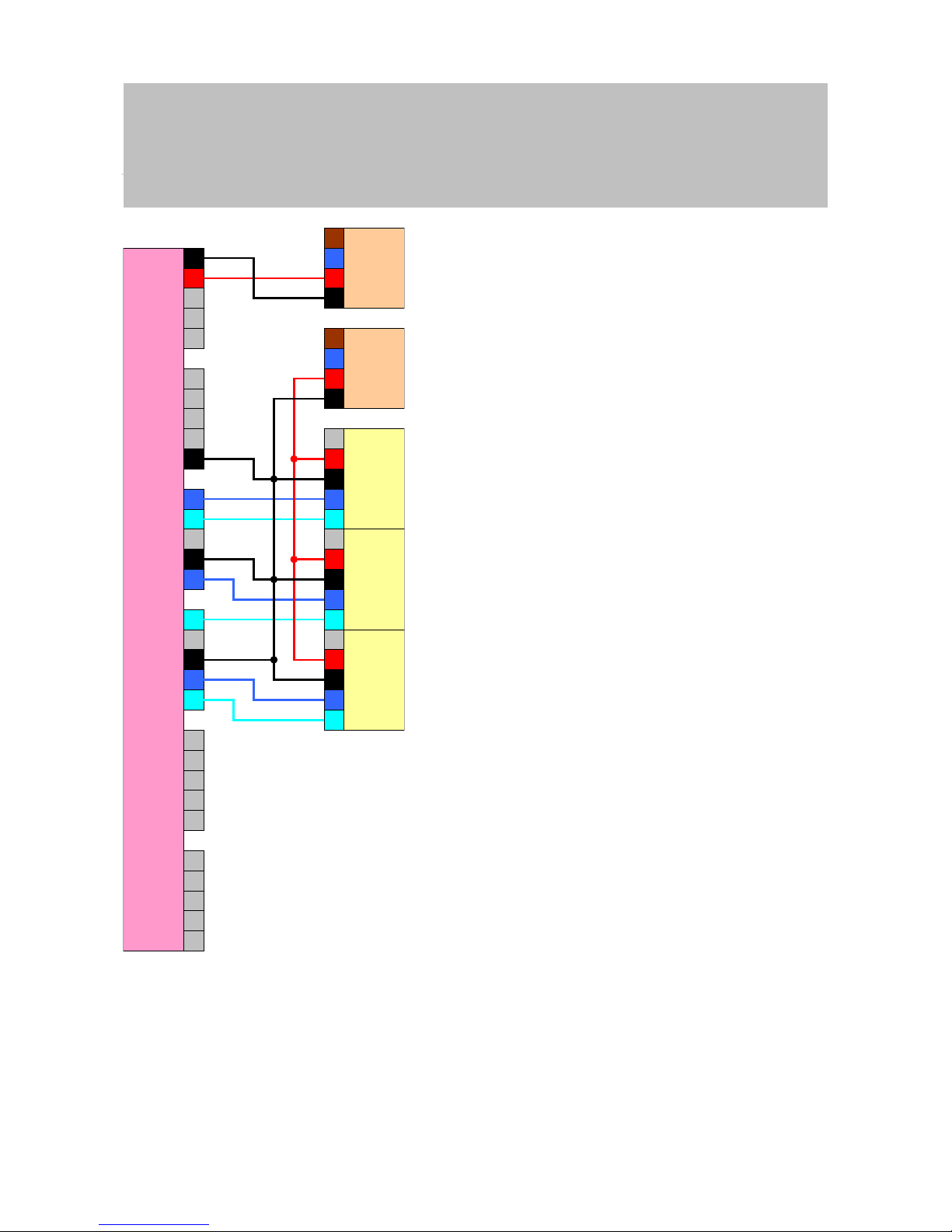
Manual
SmartRelais 3 Advanced
59 / 135
SimonsVoss
6 | Setting up
-
+
1(1)
<
1(2)
2(1)
<
2(2)
+1
-
B1
A1
+2
-
B2
A2
+3
-
B3
A3
O4
O3
O2
O1
O+
I+
-
I1
I2
I3
A
B
-
+
-
A
B
-
+
-
A
B
-
+
-
+
-
N
L
+
-
N
L
Controller
Power
supply unit
Reader
Reader
Reader
Power
supply unit
Option 2: Using two
earth connections
This configuration uses both earth connections available on the
reader. The power supply unit's earth is wired to one earth
connection, the controller's earth to the other earth connection. This
establishes a common reference potential, allowing data transmission
to take place. Since the earth connections on the controller are
connected to one another electrically, it does not matter which one is
Page 60

Manual
SmartRelais 3 Advanced
60 / 135
SimonsVoss
6 | Setting up
connected to the earth (see Controller [}14] for details). It is sufficient
if one earth connection on the controller is connected to the readers'
earth systems.
This configuration is ideal if you wish to reduce the number of
branches in the wiring. Both configurations function in exactly the
same way.
-
+
1(1)
<
1(2)
2(1)
<
2(2)
+1
-
B1
A1
+2
-
B2
A2
+3
-
B3
A3
O4
O3
O2
O1
O+
I+
-
I1
I2
I3
A
B
-
+
-
+
-
N
L
+
-
N
L
A
B
-
+
-
A
B
-
+
-
Controller
Power
supply unit
Reader
Reader
Reader
Power
supply unit
Page 61

Manual
SmartRelais 3 Advanced
61 / 135
SimonsVoss
6 | Setting up
6.4.5.2 Connecting one or more buttons
As a general rule, buttons are always connected to the digital inputs on the
controller. Up to three buttons can be connected per controller (see
Controller [}14]). Button functions can be configured in LSM. The inputs
are low in a non-actuated state, i.e. logic 0. They are registered as high if
the voltage present exceeds a threshold value (see Properties [}121]). The
threshold voltage can be exceeded (as shown) by connecting to the
controller's operating voltage. Alternatively, any voltage within the specified
levels (see Properties [}121]) can be used with a common reference
potential to the controller.
Option 1: Using the I+
connection
In addition to the digital inputs, there is also an output which transmits
an operating voltage of-1VDC to make it easier to use buttons. The
output can be used to increase the inputs to a higher voltage than the
threshold voltage, thus switching to logic 1.
Page 62
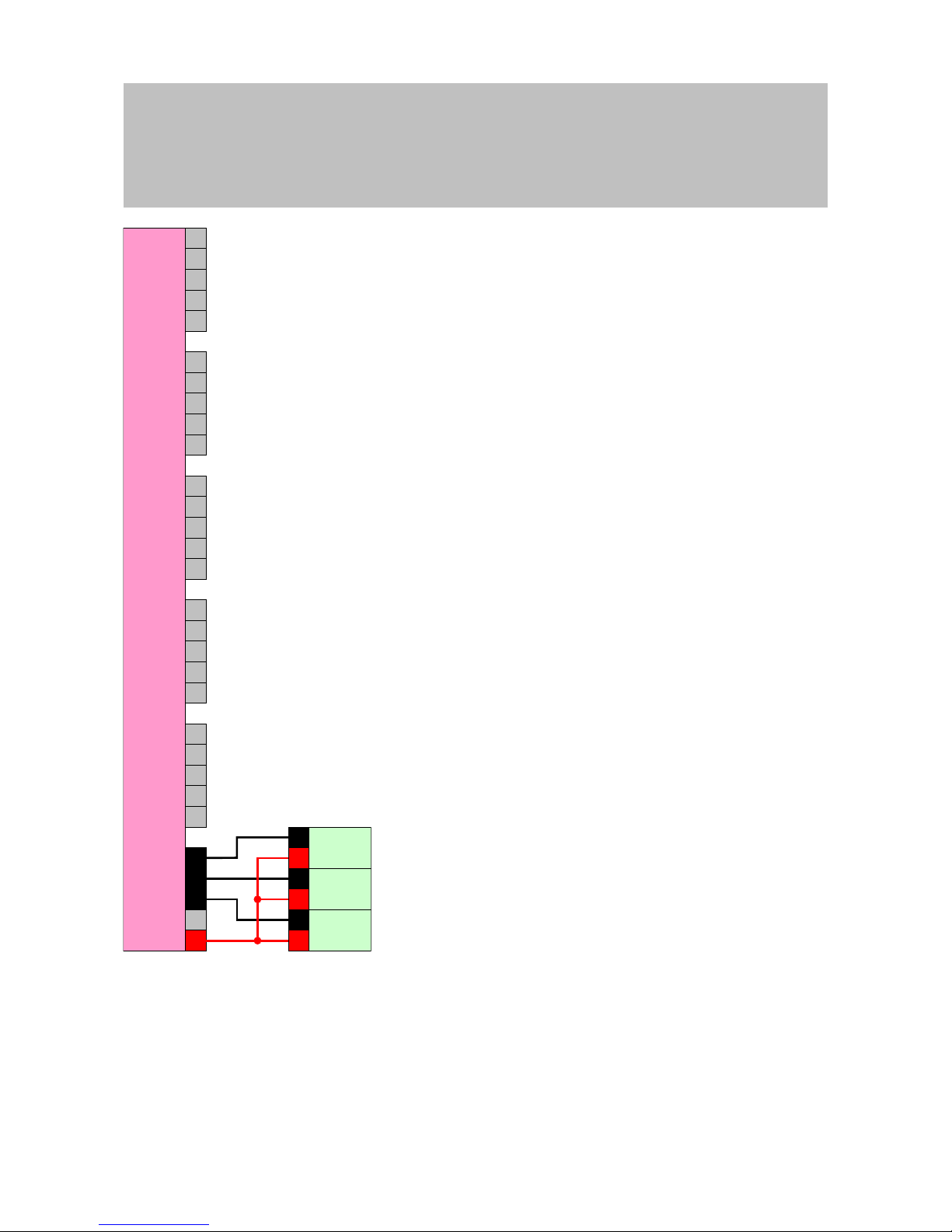
Manual
SmartRelais 3 Advanced
62 / 135
SimonsVoss
6 | Setting up
-
+
1(1)
<
1(2)
2(1)
<
2(2)
+1
-
B1
A1
+2
-
B2
A2
+3
-
B3
A3
O4
O3
O2
O1
O+
I+
-
I1
I2
I3
1
2
1
2
1
2
Controller
Button
Button
Button
Option 2: Using V
IN
If I+ is not to be used, another voltage can be used with a common
reference potential (same earth) with the controller – from the power
supply unit in this case. This option is recommended if the power
supply unit and buttons are close to one another, but are far from the
controller. There is no need to install another cable (the I+ to be
precise) in this case.
Page 63
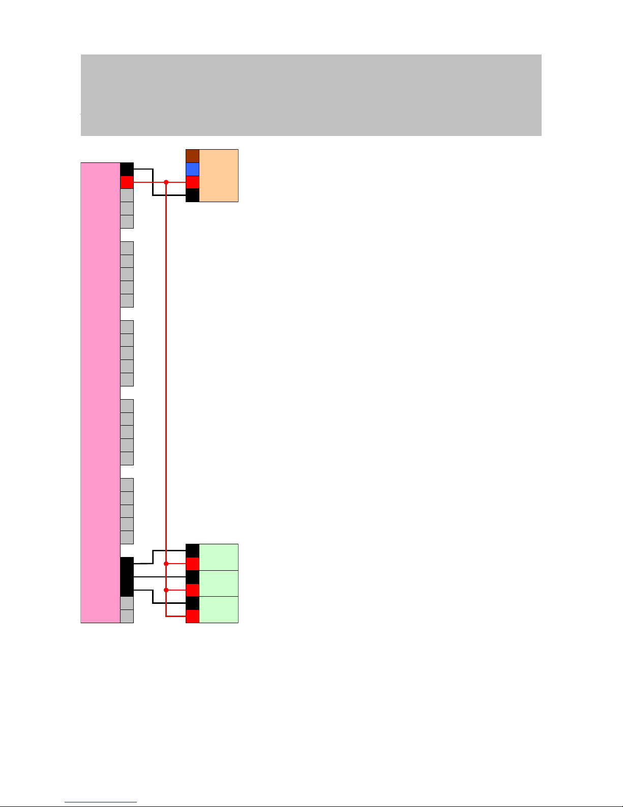
Manual
SmartRelais 3 Advanced
63 / 135
SimonsVoss
6 | Setting up
-
+
1(1)
<
1(2)
2(1)
<
2(2)
+1
-
B1
A1
+2
-
B2
A2
+3
-
B3
A3
O4
O3
O2
O1
O+
I+
-
I1
I2
I3
1
2
1
2
1
2
L
N
-
+
Controller
Button
Power
supply unit
Button
Button
6.4.5.3 Connecting one or more SmartOutput modules
SmartOutput modules require a supply voltage which may differ from the
controller's supply voltage. For this reason, it is recommended to use their
own power supply unit. SmartOutput modules are connected in parallel on
the bus (A, B). The bus is connected to the controller instead of a third
Page 64

Manual
SmartRelais 3 Advanced
64 / 135
SimonsVoss
6 | Setting up
reader. To ensure the SmartOutput modules are activated correctly, an
address needs to be configured on each SmartOutput module (see
SmartOutput module manual).
IMPORTANT
If the controller's power supply unit delivers 12VDC and sufficient electricity,
there is no need for a power supply unit for the SmartOutput modules; the
controller's power supply can be used instead. In this case, the earth system in the SmartOutput modules is connected to the controller power supply unit and VIN in the SmartOutput modules with the power supply unit's
12VDC.
Page 65

Manual
SmartRelais 3 Advanced
65 / 135
SimonsVoss
6 | Setting up
-
+
1(1)
<
1(2)
2(1)
<
2(2)
+1
-
B1
A1
+2
-
B2
A2
+3
-
B3
A3
O4
O3
O2
O1
O+
I+
-
I1
I2
I3
C
A
B
I+
I-
Out
-
A-
K1
A+
+
K2
L
N
-
+
C
A
B
I+
I-
Out
-
A-
K1
A+
+
K2
C
A
B
I+
I-
Out
-
A-
K1
A+
+
K2
Power
supply unit
SREL3
(Advanced)
controller
SOM
SOM
SOM
Configuring the address for modules
Each connected module is actuated using its address. This address is set
on the address switch. The following addresses are permitted:
Module Address
Module 1 0 (initial setting in the factory)
Module 2 1
Page 66

Manual
SmartRelais 3 Advanced
66 / 135
SimonsVoss
6 | Setting up
Module Address
Module 3 2
Module 4 3
Module 5 4
Module 6 5
Module 7 6
Module 8 7
Module 9 8
Module 10 9
Module 11 A
Module 12 B
Module 13 C
Module 14 D
Module 15 E
Module 16 F
1. Press the sides of the transparent inlay together.
2. Remove the transparent inlay.
3. Use a screwdriver to configure the address as per the table.
4. Insert the transparent inlay again.
6.4.5.4 Using the serial interface
The digital outputs used for the serial interface are open drain connections.
This means that a pull-up resistance in the data lines and 3–24VDC are
required for operation as a serial interface. The O+ connection can be used
for this purpose. A value of 1kΩ is recommended. The earth system in the
controller and the earth system in the third-party system must also be
connected for data transmission.
You can obtain detailed information and the specifications from Support
(see Help and contact). The required pull-up resistances may already be
integrated in your third-party system. In doubt, please ask the manufacturer
of your third-party system.
Wiegand 26-bit and 33bit
The controller can communicate with systems which use one of the
Wiegand protocols. Once an authorised identification medium is
detected, the data are forwarded to the third-party system via the
serial interface. The controller must be wired as follows to make this
possible.
Page 67

Manual
SmartRelais 3 Advanced
67 / 135
SimonsVoss
6 | Setting up
-
+
1(1)
<
1(2)
2(1)
<
2(2)
+1
-
B1
A1
+2
-
B2
A2
+3
-
B3
A3
O4
O3
O2
O1
O+
I+
-
I1
I2
I3
GND
CLS
D1
D0
Third-party
system
Controller
1-10k
1-10k
1-10k
Primion, Siemens Cerpass, Kaba Benzing,
Gantner Legic and Isgus
The controller can communicate with systems which use one of the
protocols. Once an authorised identification medium is detected, the
data are forwarded to the third-party system via the serial interface.
The controller must be wired as follows to make this possible.
Page 68

Manual
SmartRelais 3 Advanced
68 / 135
SimonsVoss
6 | Setting up
-
+
1(1)
<
1(2)
2(1)
<
2(2)
+1
-
B1
A1
+2
-
B2
A2
+3
-
B3
A3
O4
O3
O2
O1
O+
I+
-
I1
I2
I3
GND
CLS
CLK
DATA
Third-party
system
Controller
1-10k
1-10k
1-10k
6.4.5.5 Wiring in lift
Lift cabs are connected to the external system via trailing cables. The
number of available lines is limited by the trailing cable type. You can save
on free lines if you decide on a configuration with few lines.
Page 69

Manual
SmartRelais 3 Advanced
69 / 135
SimonsVoss
6 | Setting up
ATTENTION
Malfunctions due to voltage drop
The physically induced voltage drop in the trailing cable may cause low
voltages in power supplies which come from outside the cab.
1. Take the cable length into account.
2. Switch to a version with power supply in the cab if necessary (see
Common earth with power supply [}69] and Common earth with
SREL3 components [}70]).
3. Make the cable gauge larger by merging lines in the trailing cable.
Also see
2 Common earth with power supply [}69]
2 Common earth with SREL3 components [}70]
Common earth with power supply
This wiring layout presupposes that the cab already has a power supply
line connected to the outside world. In the cab, a voltage converter
transforms the voltage and provides the power to the reader and
SmartOutput modules. The power supply's earth is also used for the lift
electronics as a common reference potential for data transmission between
the reader, controller and SmartOutput module.
DANGER
Electric shock due to mains voltage
An electric shock may be caused when connecting the non-hazardous
earth (low voltage) to a conductor which carries the mains voltage.
1. Only use conductors with a low-voltage potential (<42V) as a common
earth cable!
2. Protect live cables, so people do not touch them accidentally!
Page 70

Manual
SmartRelais 3 Advanced
70 / 135
SimonsVoss
6 | Setting up
-
+
1(1)
<
1(2)
2(1)
<
2(2)
+1
-
B1
A1
+2
-
B2
A2
+3
-
B3
A3
O4
O3
O2
O1
O+
I+
-
I1
I2
I3
A
B
-
+
-
+
-
N
L
+
-
N
L
C
A
B
I+
I-
Out
-
A-
K1
A+
+
K2
+
-
+out
-out
+in
-in
Controller
Power
supply unit
Voltage
converter
Reader
SOM
Trailing cable
Lift
electronics
Power
supply unit
Common earth with SREL3 components
This wiring layout presupposes that the cab already has a power supply
line connected to the outside world. In the cab, a voltage converter
transforms the voltage and provides the power to the reader and
SmartOutput modules. Unlike variants with a common earth line (see
Common earth with power supply [}69]), the power supply's earth line is
not used in this case; a separate line is used as a common reference
Page 71
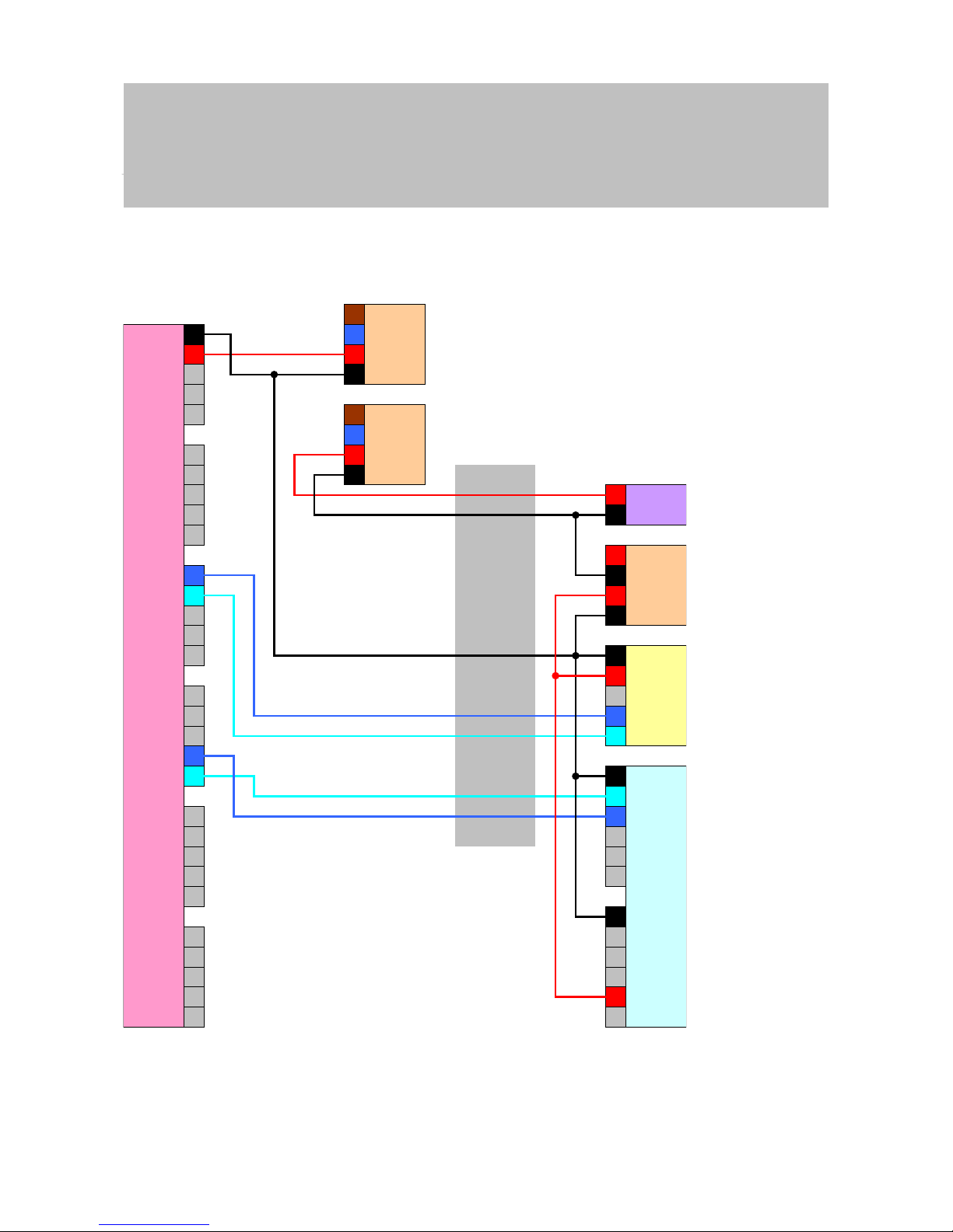
Manual
SmartRelais 3 Advanced
71 / 135
SimonsVoss
6 | Setting up
potential between, the controller, reader and SmartOutput modules instead.
Depending on the voltage converter design, the SREL3 ADV system can
thus be disconnected from the lift electronics.
-
+
1(1)
<
1(2)
2(1)
<
2(2)
+1
-
B1
A1
+2
-
B2
A2
+3
-
B3
A3
O4
O3
O2
O1
O+
I+
-
I1
I2
I3
A
B
-
+
-
+
-
N
L
+
-
N
L
C
A
B
I+
I-
Out
-
A-
K1
A+
+
K2
+
-
+out
-out
+in
-in
Controller
Power
supply unit
Voltage
converter
Reader
SOM
Trailing cable
Lift
electronics
Power
supply unit
Page 72

Manual
SmartRelais 3 Advanced
72 / 135
SimonsVoss
6 | Setting up
Power supply through trailing cable
If the cab does not have its own power supply (voltage too high or
insufficient power reserves) or is not suitable to supply power to the SREL3
ADV system for other reasons, the power supply must be provided via the
trailing cable.
Option 1: Tapping the
power supply for the
controller
This configuration dispenses with the need for a separate power
supply unit for the reader and SmartOutput modules. The data lines
are connected as described in the sections on the reader (see
Connecting one or more readers [}55]) and SmartOutput module
(see Connecting one or more SmartOutput modules [}63]).
WARNING
Overload in the power supply unit
The SmartOutput module and reader are additional power consumers.
They may overload the controller's power supply unit and cause a fire.
1. Use a power supply unit which is designated for the total continuous
currents for all connected components.
ATTENTION
Overvoltage on the SmartOutput module
The permitted supply voltage for the SmartOutput module differs from the
permitted supply voltage for the reader or controller (see Properties
[}121]).
1. Use Option 2 if the controller's supply voltage is outside the range in the
SmartOutput module's specifications.
Page 73

Manual
SmartRelais 3 Advanced
73 / 135
SimonsVoss
6 | Setting up
-
+
1(1)
<
1(2)
2(1)
<
2(2)
+1
-
B1
A1
+2
-
B2
A2
+3
-
B3
A3
O4
O3
O2
O1
O+
I+
-
I1
I2
I3
A
B
-
+
-
+
-
N
L
+
-
L
N
-
+
K2
+
A+
K1
A-
-
Out
I-
I+
B
A
C
Power
supply unit
Controller
Lift
electronics
Trailing cable
Reader
SOM
Power
supply unit
Option 2: Own power
supply unit for reader
and SmartOutput module
This configuration requires a separate power supply unit for the
reader and SmartOutput modules. The earth systems in the
controller, power supply unit and reader/SmartOutput modules must
be interconnected to establish a common reference potential for data
transmission.
Page 74
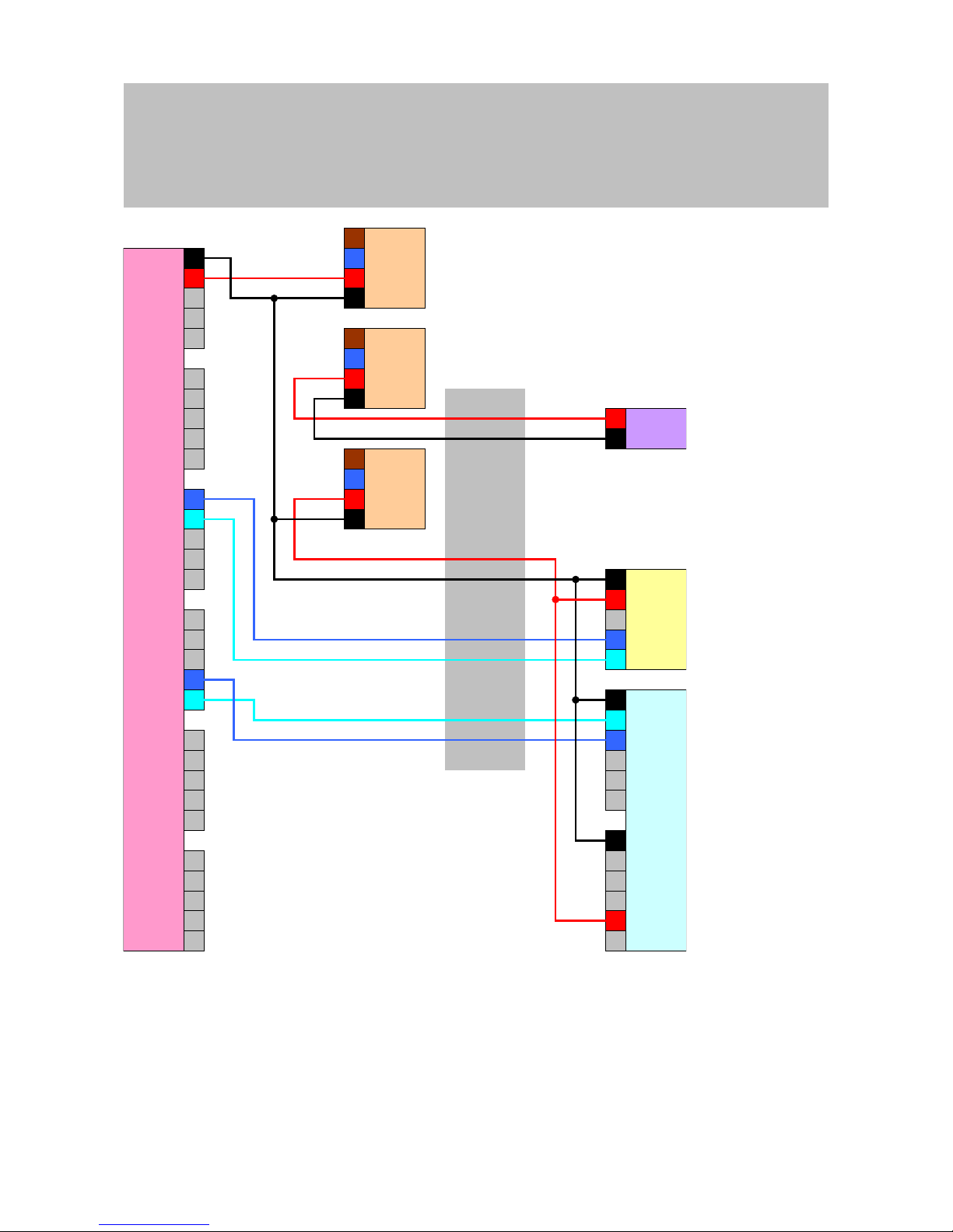
Manual
SmartRelais 3 Advanced
74 / 135
SimonsVoss
6 | Setting up
-
+
1(1)
<
1(2)
2(1)
<
2(2)
+1
-
B1
A1
+2
-
B2
A2
+3
-
B3
A3
O4
O3
O2
O1
O+
I+
-
I1
I2
I3
A
B
-
+
-
+
-
N
L
+
-
N
L
C
A
B
I+
I-
Out
-
A-
K1
A+
+
K2
+
-
+
-
N
L
Controller
Power
supply unit
Reader
SOM
Trailing cable
Lift
electronics
Power
supply unit
Power
supply unit
Power supply through the controller
This wiring layout can only be used if no SmartOutput modules are to
be used. The reader is connected via the trailing cable as described
before (see Power supply through the controller [}56]).
Page 75
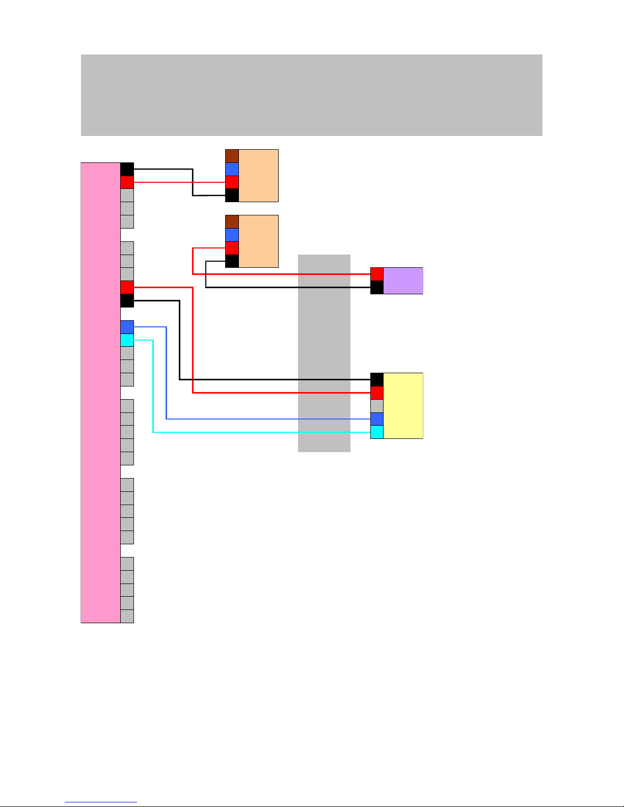
Manual
SmartRelais 3 Advanced
75 / 135
SimonsVoss
6 | Setting up
-
+
1(1)
<
1(2)
2(1)
<
2(2)
+1
-
B1
A1
+2
-
B2
A2
+3
-
B3
A3
O4
O3
O2
O1
O+
I+
-
I1
I2
I3
A
B
-
+
-
+
-
N
L
+
-
L
N
-
+
Controller
Power
supply unit
Reader
Trailing cable
Lift
electronics
Power
supply unit
Controller-fed reader with SmartOutput modules
The reader is connected as described before (see Power supply
through the controller [}56]). The SmartOutput modules are also
powered via a power supply unit outside the cab. The SmartOutput
modules' earth system must be connected to the controller's earth
system.
Page 76

Manual
SmartRelais 3 Advanced
76 / 135
SimonsVoss
6 | Setting up
-
+
1(1)
<
1(2)
2(1)
<
2(2)
+1
-
B1
A1
+2
-
B2
A2
+3
-
B3
A3
O4
O3
O2
O1
O+
I+
-
I1
I2
I3
A
B
-
+
-
+
-
N
L
+
-
N
L
C
A
B
I+
I-
Out
-
A-
K1
A+
+
K2
+
-
+
-
N
L
Controller
Power
supply unit
Reader
SOM
Trailing cable
Lift
electronics
Power
supply unit
Power
supply unit
IMPORTANT
There is also no need for a power supply unit for the SmartOutput module if
the controller has a 12VDC power supply unit. The SmartOutput module's
VIN is then not connected to its own power supply unit but to the controller's
VIN instead (compare Power supply through trailing cable [}72]).
Page 77

Manual
SmartRelais 3 Advanced
77 / 135
SimonsVoss
6 | Setting up
WARNING
Overload in the power supply unit
The SmartOutput module and reader are additional power consumers.
They may overload the controller's power supply unit and cause a fire.
1. Use a power supply unit which is designated for the total continuous
currents for all connected components.
Page 78

Manual
SmartRelais 3 Advanced
78 / 135
SimonsVoss
7 | Installation
7 Installation
Controller
The controller can be installed horizontally or vertically. You can use
the integrated fastening holes to install it safely and easily in a
horizontal position (see Drilling templates [}132]).
ATTENTION
Adverse effect on reception due to interferences
This device communicates wirelessly. Wireless communication can be affected or may fail due to metal surfaces or interference.
1. Do not fit the device to metal surfaces.
2. Keep the device away from sources of electrical or magnetic
interference.
ATTENTION
Unauthorised access
Unauthorised persons may short-circuit the electric contacts in the controller.
1. Install the controller in an environment which is protected against
unauthorised access.
ATTENTION
Malfunctions due to weather conditions
The controller is not protected against splashing water or other weather influences.
1. Install the controller in an environment which is protected against
weather influences.
Reader
The reader can be mounted in any position.
ATTENTION
Adverse effect on reception due to interferences
This device communicates wirelessly. Wireless communication can be affected or may fail due to metal surfaces or interference.
1. Do not fit the device to metal surfaces.
2. Keep the device away from sources of electrical or magnetic
interference.
ATTENTION
Malfunctions due to weather conditions
The reader is not protected against splashing water or other weather influences.
1. If you wish to use the reader in an environment which is not protected
against splashing water, use the WP version.
2. Ensure full protection against splashing water with additional sealants.
SmartOutput module
The SmartOutput module is designed for fitting onto a DIN rail.
Page 79

Manual
SmartRelais 3 Advanced
79 / 135
SimonsVoss
8 | SREL3 ADV in LSM
8 SREL3 ADV in LSM
8.1 Changing over from SREL2 to SREL3.ADV
It is possible to change between SmartRelay system generations. Contact
Support to ensure a smooth changeover process (see Help and contact).
8.2 Access list
IMPORTANT
The access list is only available in the .ZK version.
8.2.1 Import access list
The SmartRelay 3 can be configured in such a way that all identification
attempts, including unauthorised ones, are saved to the access list. You
can read this access list. Access list readouts can also be automated in
Task Manager (see LSM manual).
8.2.1.1 Reading the access list with USB cable
Proceed as follows if you wish to read the access list using a USB
connection:
ü Components wired correctly (see wiring [}55]).
ü Components connected to power.
ü Controller connected to computer with USB cable.
1. Mark the entry on the SmartRelay 3 controller in the matrix.
2. Use |Programming| to select the Read highlighted locking device/set
time item.
Page 80

Manual
SmartRelais 3 Advanced
80 / 135
SimonsVoss
8 | SREL3 ADV in LSM
ð The "Read lock" window will open.
3. Open the Type drop-down menu.
Page 81

Manual
SmartRelais 3 Advanced
81 / 135
SimonsVoss
8 | SREL3 ADV in LSM
4. Select the "USB link to the TCP nodes" item.
5. Click on the Read button.
ð "G2 SmartRelay 3" window opens.
6. Click on the Read button.
7. Click on the Audit Trail button.
ð Access list is displayed.
8.2.1.2 Reading the access list over network
Proceed as follows if you wish to read the access list using a network
connection:
ü Components wired correctly (see wiring [}55]).
ü Components connected to power.
ü Controller has already been programmed.
ü Controller connected to computer via network.
1. Mark the entry on the SmartRelay 3 controller in the matrix.
2. Use |Programming| to select the Read highlighted locking device/set
time item.
Page 82

Manual
SmartRelais 3 Advanced
82 / 135
SimonsVoss
8 | SREL3 ADV in LSM
ð The "Read lock" window will open.
3. Open the Type drop-down menu.
Page 83
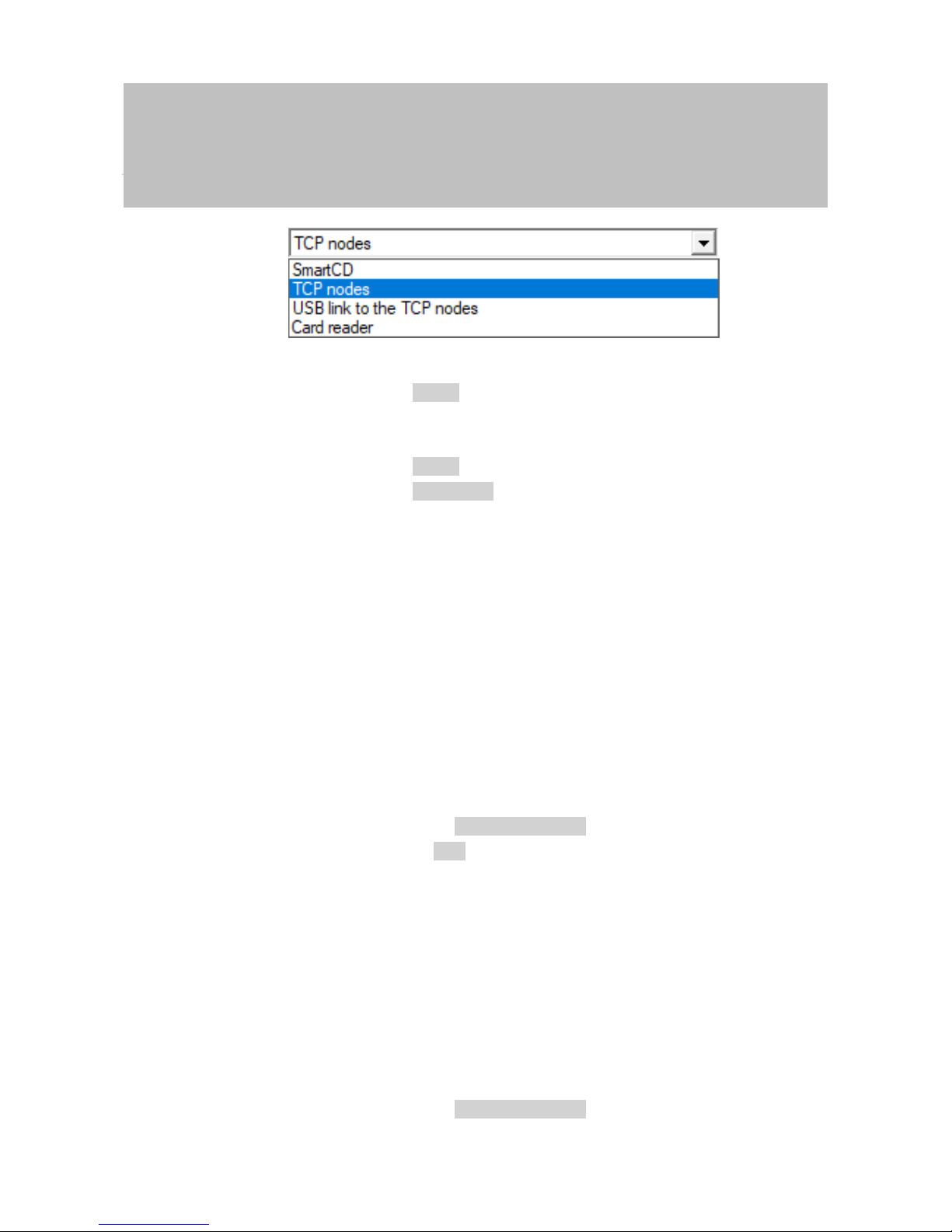
Manual
SmartRelais 3 Advanced
83 / 135
SimonsVoss
8 | SREL3 ADV in LSM
4. Select the "TCP nodes" item.
5. Click on the Read button.
ð Locking device is read.
ð The "G2 Smart Relay 3" window will open.
6. Click on the Read button.
7. Click on the Audit Trail button.
ð Access list is displayed.
8.2.2 Resetting the access list
If you wish to delete the access list permanently, you must delete it in LSM
and in the controller. The access list is synchronised between the controller
and LSM and stored in both. The controller features a built-in memory
module for this purpose.
8.2.2.1 Resetting the access list with USB cable
Deleting the access list
in the controller
Reset the controller (see Resetting controller with a USB cable [}29]).
Deleting the access list
in LSM
1. Double-click on the entry in the matrix to open the settings for
SmartRelay3.
2. Change to the [Audit Trail] tab.
3. Click on the Delete Audit Trail button.
4. Press on OK to accept query.
ð Access list is now deleted.
Programming the controller
Resetting the controller results in a programming requirement.
Execute programming for the controller (see Programming [}24]).
8.2.2.2 Resetting the access list over network
Deleting the access list
in the controller
Reset the controller (see Resetting controller over the network
[}31]).
Deleting the access list
in LSM
1. Double-click on the entry in the matrix to open the settings for
SmartRelay3.
2. Change to the [Audit Trail] tab.
3. Click on the Delete Audit Trail button.
Page 84

Manual
SmartRelais 3 Advanced
84 / 135
SimonsVoss
8 | SREL3 ADV in LSM
4. Press on OK to accept query.
ð Access list is now deleted.
Programming the controller
Resetting the controller results in a programming requirement.
Execute programming for the controller (see Programming [}24]).
8.2.3 Event logging of unauthorised accesses
Only authorised accesses are logged in storage mode. There is an option
to log unauthorised access attempts too.
ü LSM 3.4 or higher installed.
ü Components wired correctly (see wiring [}55]).
ü Components connected to power.
1. Double-click on the SmartRelay 3 entry in the matrix to open the
settings.
2. Change to the [Configuration/Data] tab.
3. Enable the Log unauthorised attempts checkbox.
4. Click on the Apply button.
5. Click on the Exit button.
6. Execute programming (see Programming [}24]).
ð Unauthorised access attempts are now also logged.
8.3 Flip-flop
The switching time for the relay in the controller can be freely programmed
between 0s and 25s. If the controller relay needs to be permanently
operated, you can activate flip-flop mode.
ATTENTION
Changing over the relay contact if power fails
The relays in the controller are not bi-stable. Consequently, permanent
power is required for switched mode. Relays are no longer supplied with
electricity if there is a power outage. In such cases, they switch to a poweroff state even without using an identification medium, depending on the original position.
1. Connect external components in such a way that a power-off state
poses no risks.
IMPORTANT
The flip-flop option is not available if the SREL3 ADV system is used with
SmartOutput modules.
ü LSM 3.4 SP1 or higher installed.
ü Components connected to power.
ü Components wired correctly (see wiring [}55]).
Page 85

Manual
SmartRelais 3 Advanced
85 / 135
SimonsVoss
8 | SREL3 ADV in LSM
ü Controller has already been programmed.
1. Double-click on the SmartRelay 3 entry in the matrix to open the
settings.
2. Change to the [Configuration/Data] tab.
3. Enable the Flip Flop checkbox.
4. Click on the Apply button.
5. Click on the Exit button.
6. Execute programming (see Programming [}24]).
ð Flip-flop mode is activated.
Also see
2 Programming [}24]
8.4 Time budgets
Time budgets are a convenient way to ensure regular identification media
updating in the virtual network. If a time budget is issued, which must be
uploaded to a gateway, users are forced to use their identification medium
on the gateway on a regular basis. During this process, not only is the time
budget uploaded, but other updates are also transmitted.
Identification media may become lost or stolen. Issuing a time budget
ensures that identification media are automatically no longer authorised on
the locking devices, because their time budget can no longer be uploaded
once rights are withdrawn. Issuing a time budget thus increases security in
the locking system.
8.4.1 Time budget template for new locking system identification media
ü Controller has already been programmed.
ü Components wired correctly (see wiring [}55]).
ü Components connected to power.
ü Controller linked to the computer via USB or TCP/IP.
ü Virtual network set up.
ü Controller set up as a gateway.
1. Click on the ... button.
2. Change to the [Name] tab.
3. Select one of the options in the "Dynamic time window for G2
transponder" section.
4. Enter the number of hours if required.
5. Click on the Apply button.
ð Global time budget set.
Page 86

Manual
SmartRelais 3 Advanced
86 / 135
SimonsVoss
8 | SREL3 ADV in LSM
6. Click on the Exit button.
7. Execute programming (see Programming [}24]).
ð Newly created identification media automatically apply this time budget
setting when they are created.
IMPORTANT
If a differing time budget or even no time budget is to be assigned to identification media which have already been created, you can issue them a time
budget on an individual basis.
1. Double-click on the entry in the matrix to open the identification
medium's properties.
2. Switch to the [Configuration] tab.
3. Issue an individual time budget in the "Dynamic time window" section.
4. Click on the Transmit button.
5. Click on the Exit button.
ð Individual time budget assigned.
8.4.2 Ignoring activation/expiry date
Identification media can be given a validity date. This validity date can be
ignored if identification media need to be used regardless.
ü Controller has already been programmed.
ü Components wired correctly (see wiring [}55]).
ü Components connected to power.
1. Double-click on the SmartRelay 3 entry in the matrix to open the
settings.
2. Change to the [Configuration/Data] tab.
3. Enable the Ignore activation or expiry date checkbox.
4. Click on the Apply button.
5. Click on the Exit button.
6. Execute programming (see Programming [}24]).
8.5 Consequences in the event of a network failure
If the network fails, only part of the information will still be transferred:
– Time budgets and buffer-stored block IDs are still transmitted from the
controller to the identification media. The locking system continues to
function.
Page 87

Manual
SmartRelais 3 Advanced
87 / 135
SimonsVoss
8 | SREL3 ADV in LSM
– Block feedback signals are transmitted from the identification media to
the controller. The physical access list is also transmitted to the
controller in the case of cards. All information is buffered in the
controller. Once connection is re-established, the controller transmits
the stored information to LSM.
– Authorisation changes are not edited in the virtual network.
– Input events are not transmitted to the database and expire.
8.6 Signal settings
In some cases, an optical or audible feedback signal may not be wanted.
You can also change signal settings as you wish.
ü LSM 3.4 or higher installed.
ü Controller has already been programmed.
ü Components wired correctly (see wiring [}55]).
ü Components connected to power.
1. Double-click on the SmartRelay 3 entry in the matrix to open the
settings.
2. Change to the [Configuration/Data] tab.
3. Click on the Extended configuration button.
ð The "Extended configuration" window will open.
4. Enable or disable the Turn off LED checkbox.
5. Enable or disable the Turn off beeper checkbox.
6. Click on the OK button.
Page 88

Manual
SmartRelais 3 Advanced
88 / 135
SimonsVoss
8 | SREL3 ADV in LSM
ð Window closes.
7. Click on the Apply button.
8. Click on the Exit button.
9. Execute programming (see Programming [}24]).
ð Signalling has been adjusted.
8.7 Operation as interface
The SREL3 ADV system can be used to actuate a third-party system with
identification media. You can select the specified interfaces for this purpose
(see Controller [}121]). See Using the serial interface [}66] on wiring. You
can receive detailed specifications on the interfaces offered from Support
(see Help and contact). If data need to be transferred via the serial
interface, then the serial interface needs to be enabled and the
corresponding protocol configured:
ü Controller has already been programmed.
ü Components wired correctly (see wiring [}55]).
ü Components connected to power.
1. Double-click on the SmartRelay 3 entry in the matrix to open the
settings.
2. Change to the [Configuration/Data] tab.
3. Click on the Extended configuration button.
ð The "Extended configuration" window will open.
4. Open the Interface drop-down menu.
Page 89
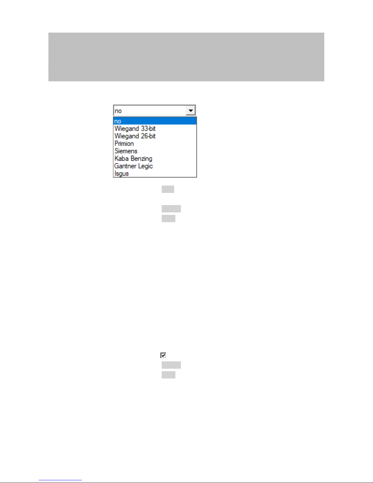
Manual
SmartRelais 3 Advanced
89 / 135
SimonsVoss
8 | SREL3 ADV in LSM
5. Select the entry which corresponds to your third-party system.
6. Click on the OK button.
ð Window closes.
7. Click on the Apply button.
8. Click on the Exit button.
9. Execute programming (see Programming [}24]).
ð Data are emitted via the serial interface.
8.8 Near-field option
A reduced reader range is required in some situations. The near-field
option reduces the reader range for transponders. This reduces the
influence of possible interferences and prevents the transponder from
overriding.
ü LSM 3.4 or higher installed.
ü Components wired correctly (see wiring [}55]).
ü Components connected to power.
1. Double-click on the SmartRelay 3 entry in the matrix to open the
settings.
2. Change to the [Configuration/Data] tab.
3. Enable the Close-up range mode checkbox.
4. Click on the Apply button.
5. Click on the Exit button.
6. Execute programming (see Programming [}24]).
ð The near-field option is activated.
8.9 Switching interval
You can freely configure the duration of opening between 0s and 25s. The
opening interval configured on the controller also applies to the
SmartOutput modules.
Page 90

Manual
SmartRelais 3 Advanced
90 / 135
SimonsVoss
8 | SREL3 ADV in LSM
ATTENTION
Unintentional opening of the SmartOutput module
If a pulse length of 0s has been configured in LSM, the SmartOutput module still activates for about three seconds.
IMPORTANT
Long release by SmartOutput modules not supported
SmartOutput modules use the G1 protocol. The G1 protocol does not support the Long opening function. The SmartOutput modules used open for
the time configured on the controller regardless of this setting on the
transponder.
ü Components wired correctly (see wiring [}55]).
ü Components connected to power.
1. Double-click on the SmartRelay 3 entry in the matrix to open the
settings.
2. Change to the [Configuration/Data] tab.
3. Enter the desired pulse length.
4. Click on the Apply button.
5. Click on the Exit button.
6. Execute programming (see Programming [}24]).
ð Switching interval is set.
8.10 Software reset
You can initiate a software reset in LSM. If the controller has been reset by
a different LSM, LSM is no longer able to activate the reset controller. LSM
still contains information on the controller which is no longer up to date. The
software reset clears all the controller information saved in LSM in the
software. This means that LSM and the controller are synchronised once
more (both reset) and LSM can address the controller again.
1. Double-click on the SmartRelay 3 entry in the matrix to open the
settings.
2. Change to the [Configuration/Data] tab.
3. Click on the Software reset button.
ð The "LockSysMgr" window will open.
Page 91
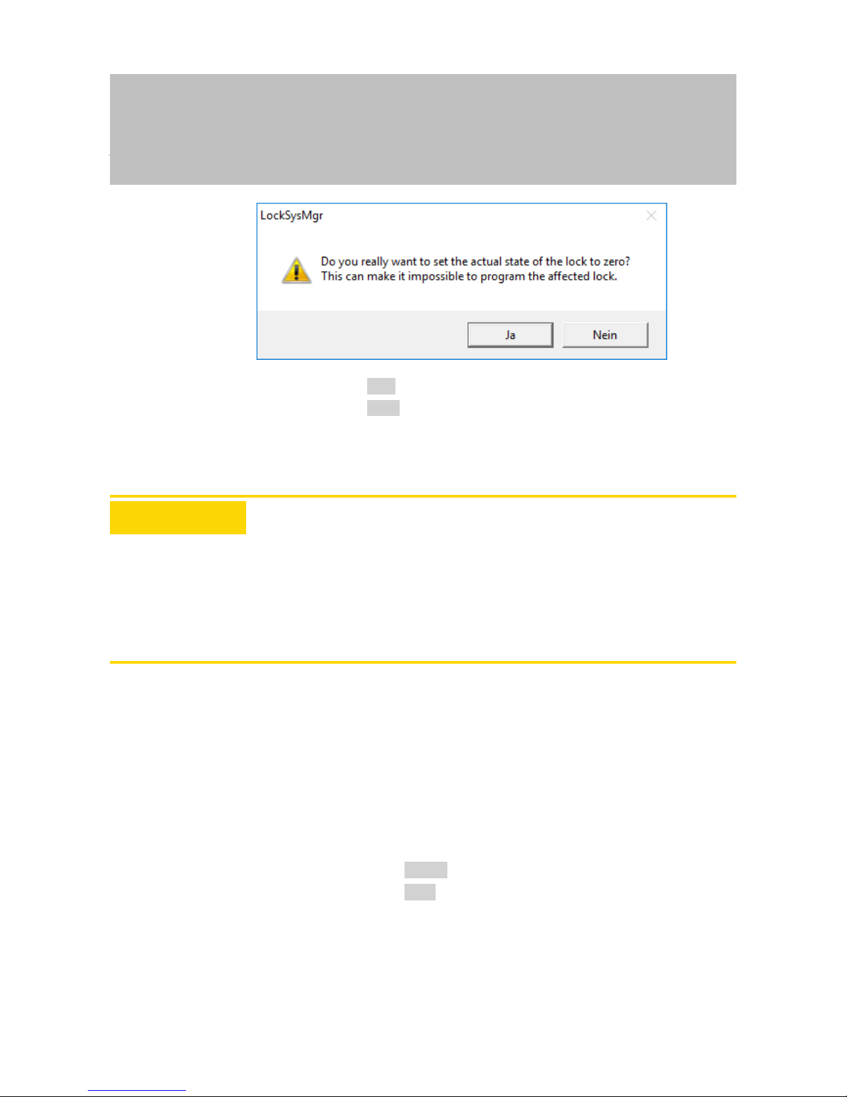
Manual
SmartRelais 3 Advanced
91 / 135
SimonsVoss
8 | SREL3 ADV in LSM
4. Click on the OK button.
5. Click on the Yes button.
ð Software reset has been completed.
8.11 Time switch-over function
ATTENTION
Unintentional opening due to use with SmartOutput module
The opening behaviour with a SmartOutput module in conjunction with time
zone control deviates from the opening behaviour without the SmartOutput
module.
All relays in the SmartOutput module are switched.
1. See the sections on Extended configuration with SmartOutput modules
[}94] and Extended configuration without SmartOutput module
[}93].
The fifth group in the time zone plan is relevant for time change-over.
Assignment of a time
zone plan
ü LSM launched.
ü SREL3 ADV System added.
ü Time zone plan added.
1. Double-click on the SmartRelay 3 entry in the matrix to open the
settings.
2. Change to the [Door] tab.
3. Open the Time zone drop-down menu.
4. Select your time zone.
5. Click on the Apply button.
6. Click on the Exit button.
ð Time zone is selected.
Activating time zone
control and time
change-over
Whereas time zone control itself can only influence identification
media authorisations, the time change-over also activates timedependent switching of the relay in the controller. Both need to be
activated.
Page 92

Manual
SmartRelais 3 Advanced
92 / 135
SimonsVoss
8 | SREL3 ADV in LSM
ü LSM launched.
ü SREL3 ADV System added.
ü Time zone plan assigned.
1. Double-click on the SmartRelay 3 entry in the matrix to open the
settings.
2. Change to the [Configuration/Data] tab.
3. Enable the Time zone management checkbox.
4. Enable the Time switching checkbox.
5. Click on the Extended configuration button.
ð The "Extended configuration" window will open.
6. Set the options for automatic and manual locking and unlocking
in the "Time-based switching" section as you require (see
Extended configuration without SmartOutput module [}93]
and Extended configuration with SmartOutput modules [}94]).
7. Click on the OK button.
ð Window closes.
8. Click on the Apply button.
9. Click on the Exit button.
ð Time zone control and time change-over are activated.
Editing the time zone
plan
See LSM manual to edit the time zone plan.
Page 93

Manual
SmartRelais 3 Advanced
93 / 135
SimonsVoss
8 | SREL3 ADV in LSM
8.11.1 Extended configuration without SmartOutput module
Unlocking in the authorised time period (close relay contacts)
Unlocking automatically Unlocking manually
always only if locked always only if locked
Controller: Closes relay contacts (unlocked) as soon as
authorisation starts in
the time zone plan.
Behaves in the same
way as a flip-flop for
the remaining authorised time period.
Controller: Closes relay contacts (unlocked) as soon as
authorisation starts in
the time zone plan. No
influence by identification media for the rest
of the authorised time
period.
Controller: Closes relay contacts (unlocked) as soon as
identification medium
is activated after authorisation starts in
the time zone plan.
Behaves in the same
way as a flip-flop for
the remaining authorised time period.
Controller: Closes relay contacts (unlocked) as soon as
identification medium
is activated after authorisation starts in
the time zone plan. No
influence by identification media for the rest
of the authorised time
period.
Locking in the non-authorised time period (open relay contacts)
Locking automatically Locking manually
always only if locked always only if locked
Controller: Opens re-
lay contacts (locked)
as soon as authorisation ends in the time
zone plan. Identification media close relay
contacts (unlock) during non-authorised
time period for pre-set
pulse duration.
Controller: Opens relay contacts (locked)
as soon as authorisation ends in the time
zone plan. Identification media close relay
contacts (unlock) during non-authorised
time period for pre-set
pulse duration.
Controller: Opens relay contacts (locked)
as soon as identification medium is activated. Identification
media close relay contacts (unlock) during
non-authorised time
period for pre-set
pulse duration.
Not possible
Page 94

Manual
SmartRelais 3 Advanced
94 / 135
SimonsVoss
8 | SREL3 ADV in LSM
8.11.2 Extended configuration with SmartOutput modules
Unlocking in the authorised time period (close relay contacts)
Unlocking automatically Unlocking manually
always only if locked always only if locked
Not possible
– Controller: Closes
relay contacts
(unlocked) as soon
as authorisation
starts in the time
zone plan. No
influence by
identification
media within the
authorised time
period.
– SmartOutput
module: Closes
relay contacts
(unlocked) as soon
as authorisation
starts in the time
zone plan. No
influence by
identification
media within the
authorised time
period.
Not possible
– Controller: Closes
relay contacts
(unlocked) as soon
as identification
medium is
activated after
authorisation starts
within the time
period. No
influence by
identification
media for the rest
of the authorised
time period after
that.
– SmartOutput
module: Closes
relay contacts
(unlocked) as soon
as authorisation
starts in the time
zone plan. No
influence by
identification
media for the rest
of the authorised
time period.
Page 95

Manual
SmartRelais 3 Advanced
95 / 135
SimonsVoss
8 | SREL3 ADV in LSM
Locking in the non-authorised time period (open relay contacts)
Locking automatically Locking manually
always only if locked
Not possible
Not possible
– Controller: Opens
relay contacts
(locked) as soon
as authorisation
ends in the time
zone plan.
Identification
media close relay
contacts for
configured pulse
duration for the
remaining
authorised time
period.
– SmartOutput
module: Opens
relay contacts
(locked) as soon
as authorisation
ends in the time
zone plan.
Identification
media close relay
contacts for
configured pulse
duration for the
remaining
authorised time
period.
8.12 Remote opening
You can also use LSM to operate the relay in the controller without
identification media at any time.
IMPORTANT
A remote opening takes precedence over time zone control. It also operates the relay if the relay contacts should remain open after time zone control.
Remote opening with
USB cable
ü Controller has already been programmed.
ü Components wired correctly (see wiring [}55]).
ü Components connected to power.
1. Use |Network| to select the Lock activation item.
Page 96

Manual
SmartRelais 3 Advanced
96 / 135
SimonsVoss
8 | SREL3 ADV in LSM
ð The "Activate network locks" window will open.
2. Open the Door/lock drop-down menu.
3. Select the SREL3 ADV system controller.
4. Open the Type drop-down menu.
5. Select the "USB link to the TCP nodes" item.
6. Open the Device drop-down menu.
7. Select the IP address if required.
8. Select the remote unlocking option.
9. Click on the Execute button.
ð Relay switches in the controller.
Page 97

Manual
SmartRelais 3 Advanced
97 / 135
SimonsVoss
8 | SREL3 ADV in LSM
ð "Programming successful" window is displayed.
Remote opening via
TCP/IP
ü Controller has already been programmed.
ü Components wired correctly (see wiring [}55]).
ü Components connected to power.
1. Use |Network| to select the Lock activation item.
ð The "Activate network locks" window will open.
2. Open the Door/lock drop-down menu.
3. Select the SREL3 ADV system controller.
4. Open the Type drop-down menu.
5. Select the "TCP nodes" item.
Page 98

Manual
SmartRelais 3 Advanced
98 / 135
SimonsVoss
8 | SREL3 ADV in LSM
6. Open the Device drop-down menu.
7. Select the IP address if required.
8. Select the remote unlocking option.
9. Click on the Execute button.
ð Relay switches in the controller.
ð "Programming successful" window is displayed.
8.13 Firmware update
SimonsVoss products are kept up to date and maintained at all times. It
may be necessary to enable new functions to install a new firmware
version.
Firmware updates are a complex affair which require detailed specialist
knowledge. Contact our Support to install any firmware updates (see Help
and contact). The controller may need to reset the controller.
ATTENTION
Bricking due to firmware update being interrupted
The firmware is also responsible for resetting. If the firmware is partly overwritten and the process is interrupted (connection is cut or the power supply
fails), it may no longer be possible to address or reset the device as a result
of what is known as bricking.
1. Ensure that the power supply is stable during the firmware update.
2. Ensure that the power supply is not interrupted during the firmware
update.
3. Ensure that the connection is not interrupted during the firmware
update.
8.14 Events
8.14.1 Evaluating controller inputs
The digital inputs on the SREL3 ADV system controller can be forwarded to
LSM, where they may trigger actions.
Adding an event
If you wish to use LSM or SmartSurveil (see SmartSurveil [}101]) to
evaluate an input, you first need to create the corresponding input as
an event in LSM. Only then will changes to the input also be saved in
the LSM database.
ü LSM open.
ü SREL3 ADV System added to the matrix.
1. Use |Network| to select the Event manager item.
ð The "Network event manager" window will open.
2. Click on the New button.
Page 99

Manual
SmartRelais 3 Advanced
99 / 135
SimonsVoss
8 | SREL3 ADV in LSM
ð The "New Event" window will open.
3. Enter a suitable name for the event.
4. Enter an optional description for the event.
5. Enter an optional message.
6. Open the Type drop-down menu.
7. Select the "Input Event" item.
8. Click on the Configure event button.
ð The "Input Event" window will open.
Page 100
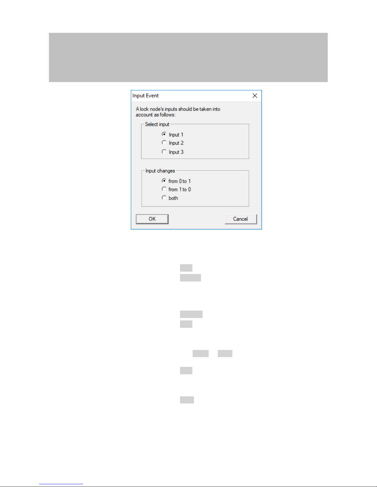
Manual
SmartRelais 3 Advanced
100 / 135
SimonsVoss
8 | SREL3 ADV in LSM
9. Select the required input in the "Select input" section.
10. Select the status change that the event should trigger in the
"Input changes" section.
11. Click on the OK button.
12. Click on the Select button to assign a locking device to the
event.
ð The "Administration" window will open.
13. Highlight one or more locking devices.
14. Click on the ← Add button.
15. Click on the OK button.
ð Window closes.
ð Locking device is assigned to the event.
16. You can use the New or Add button to assign an action if you
wish to configure an action.
17. Click on the OK button.
ð Window closes.
ð Event is displayed in the "Events" section.
18. Click on the Exit button.
ð Window closes.
ð Input is added as an event and triggers an action.
 Loading...