

Simons Voss Technologies SmartHandle WP, SmartHandle Hybrid WP, SmartHandle 3062 Instruction Leaflet
Page 1

V-2014-04 · Artikel-Nr. BS11.990500
Kurzanleitung
Smart Handle – Snap in
neue drücKerbefeStigung
Instruction leaet for snap-in Smart Handle · Notice
d’accompagnement de la Smart Handle – SnapIn ·
Bijsluiter Smart Handle SnapIn · Folleto de instrucciones
del Smart Handle con montaje SnapIn · Foglio di
istruzioni Smart Handle SnapIn ·
SmartHandle SnapIn
Краткое руководство к
Page 2

4 Inhalt.
4 Benötigte Werkzeuge zur Montage (nicht beiliegend).
4 Wichtige Hinweise.
5 Hinweise Montage.
5 Montage Smart Handle.
6 Montage Smart Handle – WP.
7 Optisches (Hybrid) / Akustisches Feedback.
8 Demontage.
8 Batteriewechsel Smart Handle WP und Hybrid WP.
8 Batteriewechsel Smart Handle – Hybrid.
9 Contents.
9 Tools required for assembly (not enclosed).
9 Important instructions.
10 installation instructions.
10 installing Smart Handle.
11 Installing Smart Handle – WP.
12 Optical (Hybrid) and audible feedback signal.
12 Disassembly.
13 Battery replacement Smart Handle WP / Hybrid WP.
13 Battery replacement Smart Handle Hybrid.
14 Contenu.
14 Outils nécessaires au montage (non fournis).
14 Remarques importantes.
15 Consignes de montage .
15 Montage du Smart Handle.
16 Montage du Smart Handle – WP .
17 Feedback optique / acoustique.
18 Démontage .
18 Remplacement des piles Smart Handle wp / Hybride WP.
18 Remplacement des piles Smart Handle – Hybride .
19 Inhoud.
19 Benodigd gereedschap voor de montage (niet bijgesloten).
19 Belangrijke instructies.
20 instructies montage.
20 Montage Smart Handle.
21 Montage Smart Handle – WP.
22 optische (Hybride) en akoestische feedback.
22 Demontage.
23 Batterijvervanging Smart Handle wp / Hybride WP.
23 Batterijvervanging Smart Handle – Hybride.
24 Contenido.
24 Herramientas necesarias para el montaje (no incluidas).
24 Notas importantes.
25 Instrucciones sobre el montaje.
25 Montaje del Smart Handle.
26 Montaje del Smart Handle – WP.
27 Señales ópticas (Híbrido) / acústicas.
28 Desmontaje.
28 Cambiar las baterías del Smart Handle WP y Híbrido WP.
29 Cambiar las baterías del Smart Handle – Híbrido.
Page 3

30 Contenuto.
30 Attrezzi necessari per il montaggio (non forniti).
30 Avvisi importanti.
31 Suggerimenti per il montaggio.
31 Montaggio Smart Handle.
32 Montaggio Smart Handle – WP.
33 Feedback ottico (Hybrid) / acustico.
34 Smontaggio.
34 Sostituzione delle batterie Smart Handle WP / Hybrid WP.
34 Sostituzione delle batterie Smart Handle – Hybrid.
35 Оглавление
35 Необходимые инструменты для монтажа (не прилагаются).
35 Важные указания.
36 Указания по монтажу.
36 Монтаж Smart Handle.
37 Монтаж Smart Handle – WP.
38 Оптическая (ГИБРИД) / акустическая обратная связь.
39 Демонтаж.
39 Замена батареек в ручке Smart Handle WP и ГИБРИД WP.
40 Замена батарейки ручки Smart Handle – ГИБРИД.
41 Abbildungen · Pictures · Image · Foto · Imagen · Immagine · Рисунки.
Page 4

inHalt.
• 2x Cover
• 2x Abdeckung
• 1x Außenbeschlag
• 1x Innenbeschlag
• 1x Drücker für Außenbeschlag
• 1x Drücker für Innenbeschlag (inkl. Inbusschraube)
• 1x Befestigungsschraube
• 1x PZ-Abdeckung (nur bei 9 mm)
• 1x Adapter für British Oval Einsteckschlösser (optional)
• 1x Beipackzettel
• 1x Werkzeug Demontage Abdeckung und Batteriewechsel
benötigte WerKzeuge zur montage (nicHt beiliegend).
• Inbusschlüssel für Drückermontage (Schlüsselweite 3 mm)
• Gabelschlüssel 19
• Kreuzschlitzschraubendreher (Akkuschrauber vorteilhaft)
WicHtige HinWeiSe.
• Der Einbau und der Batteriewechsel dürfen nur durch geschultes Fachpersonal durchgeführt werden!
• SmartHandle nicht mit Öl, Farbe oder Säuren in Verbindung bringen!
• Es sind nur Batterien zu verwenden, welche von SimonsVoss freigegeben sind!
• Die im digitalen SmartHandle 3062 eingesetzten Batterien können bei Fehlbehandlung eine Feuer- oder
Verbrennungsgefahr darstellen! Die Batterien nicht auaden, öffnen, erhitzen oder verbrennen! Nicht
kurzschließen!
• Alte bzw. verbrauchte Batterien fachgerecht entsorgen und nicht in Reichweite von Kindern aufbewahren!
• Ein Vertauschen der Polarität der Batterien kann zu Beschädigungen des SmartHandles führen!
• Bei einem Batteriewechsel immer alle Batterien erneuern!
• Bei einem Batteriewechsel die Kontakte der neuen Batterien nicht mit den Händen berühren. Verwenden
Sie hierzu saubere und fettfreie Handschuhe.
• Das SmartHandle Aktiv muss mit zwei Batterien betrieben werden!
• Das SmartHandle Hybrid muss mit vier Batterien betrieben werden!
• Das SmartHandle WP / SmartHandle Hybrid WP muss mit zwei Batterien betrieben werden.
• Beim Batteriewechsel darauf achten, dass die Elektronik bzw. Elektroniken hierbei nicht z.B. mechanisch
belastet werden bzw. anderweitig zu Schaden kommen.
• Die Elektronik auf der Innenseite darf nicht mit Feuchtigkeit in Berührung kommen.
• An der Außenhaut bzw. wenn die Außenseite z.B. mit Feuchtigkeit in Berührung kommen kann, ist
die Variante .WP zu verwenden. Hierbei werden die Kabelanschlüsse/Stecker alle in den Innenbereich
gezogen. Siehe hierzu „Montage SmartHandle WP“.
• Nicht an den Kabeln ziehen, beim Lösen von Steckverbindungen an den Steckern anfassen und diese
vorsichtig entrasten.
• Die Montage des SmartHandles kann bei Einsteckschlössern mit Klemmnuss etwas schwergängig
sein. Auf keinen Fall die Klemmnuss mechanisch bearbeiten (z.B. mit einer Feile o.ä.), da der Drücker
ansonsten seine passgenaue Führung verliert.
• Bei Verwendung des SmartHandles an feuerhemmenden Türen unbedingt darauf achten, dass die PZ-
Abdeckung auf den SnapIn aufgeschoben ist.
• Zur Demontage bzw. beim Batteriewechsel ausschließlich das Montagewerkzeug von SimonsVoss
verwenden.
• Für Beschädigungen der Türen oder der Komponenten durch fehlerhafte Montage übernimmt die
SimonsVoss Technologies GmbH keine Haftung.
• Durch fehlerhaft installierte oder programmierte SmartHandle kann der Zugang durch eine Tür versperrt
werden. Für die Folgen fehlerhafter Installationen, wie nicht möglicher Zugang zu verletzten Personen,
Sachschäden oder andere Schäden, haftet die SimonsVoss Technologies GmbH nicht.
• Das SmartHandle wirkt ausschließlich auf die Falle des Einsteckschlosses.
• Um die Tür versicherungstechnisch zu verschließen, ist ein selbstverriegelndes Panikschloss (SVP-
Schloss) zu verwenden.
• Das SimonsVoss SmartHandle darf nur für den vorgesehenen Zweck, das Öffnen und Schließen von
Türen, genutzt werden. Ein anderer Gebrauch ist nicht zulässig.
4
Page 5

• Bei Verwendung in Kombination mit Panikschlössern ist nach dem Einbau unbedingt sicherzustellen,
dass sich alle Teile des Verschlusses in einem betriebsbereiten Zustand benden und die Panikfunktion
des Einsteckschlosses gewährleistet ist.
• Änderungen bzw. technische Weiterentwicklungen können nicht ausgeschlossen werden.
• Die Dokumentation wurde nach bestem Wissen erstellt, evtl. Fehler können aber nicht ausgeschlossen
werden. Hierfür kann keine Haftung übernommen werden.
• Sollten Abweichungen von Inhalten in Fremdsprachenversionen der Dokumentation bestehen, gilt im
Zweifelsfalle das deutsche Original.
HinWeiSe montage.
Die Batterien sind bei Lieferung bereits eingebaut!
• Bei der Installation des digitalen SmartHandle Aktiv / Hybrid ist darauf zu achten, dass sich keine
niederfrequenten Störquellen im Umkreis benden.
• SmartHandle Aktiv / Hybrid sollten mindestens im Abstand von 0,5 m voneinander entfernt montiert
werden, SmartRelais bzw. Scharfschalteinheiten im Abstand von 1,5 m.
• Das SmartHandle muss bündig an der Tür anliegen. Unbedingt auf eine vorschriftsmäßige Montage
achten, damit die Stabilität und Haltbarkeit des Produktes gewährt ist.
• Bei der Montage auf keinen Fall gegen Teile des SmartHandle schlagen.
• Beide Abdeckungen der Cover sind mit einer Clipvorrichtung verschlossen. Diese dürfen ausschließlich
mit dem SimonsVoss-Montagewerkzeug demontiert werden.
• SnapIn: Bei FH-Türen (9 mm Vierkant) unbedingt darauf achten, dass die mitgelieferte PZ-Abdeckung
beim Innenbeschlag auf den SnapIn-Mechanismus aufgeschoben ist.
• Falls die Außenseite des SmartHandles mit Feuchtigkeit etc. in Berührung kommen kann, ist immer die
WP-Variante zu verwenden.
• SmartHandle vor dem Einbau programmieren! Die G1-SmartHandle Aktiv werden ab Werk im
„Lagermodus“ geliefert und können vor der Erstprogrammierung nicht mit einem Transponder betätigt
werden!
• Die Montage des SmartHandles kann bei Einsteckschlössern mit Klemmnuss etwas schwergängig
sein. Auf keinen Fall die Klemmnuss mechanisch bearbeiten (z.B. mit einer Feile o.ä.), da der Drücker
ansonsten seine passgenaue Führung verliert.
• Bei der Installation darauf achten, dass die Kabel nicht gequetscht werden bzw. auf Spannung in der Tür
verbaut werden.
• Unbedingt darauf achten, dass der Drückerverschluss nicht verkantet oder plastisch verformt wird. Der
Drücker darf nach dem Verschluss kein Spiel in horizontaler Richtung aufweisen.
• Da bei den meisten Drückern aufgrund des Designs die Abdeckungen nach der Montage nicht mehr
über diese geschoben werden können empehlt es sich diese am Anfang über den Außendrücker zu
schieben.
montage Smart Handle.
1. Optional: Drücker / Rosetten / Beschläge etc., welche an der Tür angebracht sind, demontieren.
2. Optional: Einsteckschloss in der Tür befestigen.
3. Das SmartHandle wird teilmontiert geliefert, zur Demontage bitte unter „Demontage“ schauen und die
Schritte 9-13 durchführen.
4. Bei einigen Drückern ist es nicht möglich die Abdeckung im montierten Zustand anzubringen (z.B.
gekröpfte Drücker). Bei diesen Drückern die Abdeckung (mit Logo nach außen) auf den Außendrücker
schieben. Generell ist es möglich, bei allen so zu verfahren.
5. Außendrücker in gewünschter Richtung horizonzal in den Außenbeschlag einstecken, je nachdem, ob es
sich um eine DIN links oder DIN rechts Tür handelt.
6. Drückerverschluss aufstecken (Bild 2 und Bild 3).
7. Den Außendrücker festhalten und mit dem Gabelschlüssel den Drückerverschluss bis zum Anschlag ca.
75° nach rechts verdrehen (Bild 4 und Bild 5). Bei nicht korrekter Montage ist es möglich, dass sich der
Drücker wieder lösen kann.
8. Optional: Bei einem SmartHandle für British Oval Einsteckschlösser bitte den beiliegenden Adapter auf
den SnapIn-Mechanismus des Innenbeschlags schieben.
9. Optional: Bei einem Schloss mit 8,5 mm bzw. 10 mm Vierkant die entsprechende Hülse (8 mm -> 8,5
mm bzw. 8 mm -> 10 mm) von innen durch die Nussöffnung des Einsteckschlosses schieben.
10. Optional: Bei FH-Türen (9 mm Vierkant) unbedingt darauf achten, dass die mitgelieferte PZ-Abdeckung
beim Innenbeschlag auf den SnapIn-Mechanismus aufgeschoben ist.
5
Page 6

11. Das 3-polige Kabel des Innenbeschlags in den SnapIn-Mechanismus schieben. Somit werden diese bei
der Montage gegen äußerliche Einwirkungen geschützt (Abbildung 6).
12. Die Montage des Innenbeschlags erfolgt von der Innenseite der Tür. Durch gleichzeitiges durchschieben
des Vierkants durch die Nussaufnahme und des SnapIn-Mechanismus durch die Euro-PZ/Swiss-Round/
British Oval Öffnung des Einsteckschlosses wird der Innenbeschlag an der Tür befestigt.
13. Innenbeschlag soweit durchschieben, dass dieser bündig an der Tür anliegt.
14. Die Kabel aus dem SnapIn-Mechanismus entnehmen, damit diese frei aus der Tür schauen und nicht
beschädigt werden (Abbildung 7).
15. Die Montage des Außenbeschlags erfolgt von der Außenseite der Tür. Gleichzeitig die Nuss des
Außenbeschlags auf den Vierkant und den SnapIn-Mechanismus des Außenbeschlags in den SnapIn des
Innenbeschlags schieben.
16. Außenbeschlag bis ca. 1 cm Entfernung an die Tür schieben.
17. Das 3-polige Kabel des Innenbeschlags durch das Langloch des Außenbeschlags schieben. Bitte hierbei
nicht am Kabel ziehen (Abbildung 7).
18. Das 3-polige Kabel des Innenbeschlags mit dem 3-poligen Kabel des Außenbeschlags verbinden. Dieses
kann nur in eine Richtung eingesteckt werden. Bitte hierbei nicht an den Kabeln ziehen, sondern nur die
Steckverbindung vorsichtig verrasten.
19. Das 2-polige Kabel des Außenbeschlags kann frei hängen, darf aber bei Montage des Außencovers nicht
gequetscht werden. Bitte nicht am Kabel ziehen.
20. Außen- und Innenbeschlag zusammendrücken, sodass beide bündig an der Tür anliegen.
21. Befestigungsschraube von der Innenseite der Tür durch den SnapIn-Mechanismus schieben und
handfest (ca. 5 – 7 Nm) anziehen (Abbildung 8).
22. Auf Leichtgängigkeit des Außendrückers prüfen, ansonsten liegt evtl ein Problem mit dem Schloss oder
ein Montagefehler vor. Im Zweifelsfall Komponenten demontieren und wieder bei Punkt 7 beginnen.
23. Innendrücker auf die Befestigung des Innenbeschlags bis zum Anschlag aufschieben.
24. Inbusschraube des Innendrückers handfest anziehen, sodass dieser bündig mit dem Drücker abschließt.
25. Cover über den Innendrücker schieben, sodass das Cover bündig an der Tür anliegt (Cover ist nicht
symmetrisch, bitte auf die Kennzeichnung achten, Abbildung 9).
26. Die Abdeckung des Covers über den Drücker schieben und diese vorsichtig in das Cover einklicken.
27. Cover über den Aussendrücker schieben, sodass dieser bündig an der Tür anliegt (Cover ist nicht
symmetrisch, bitte auf die Kennzeichnung achten, Abbildung 9).
28. Die Abdeckung des Außencovers über den Drücker schieben und diese vorsichtig in das Cover
einklicken.
montage Smart Handle – Wp.
1. Optional: Drücker / Rosetten / Beschläge etc., welche an der Tür angebracht sind, demontieren.
2. Optional: Einsteckschloss in der Tür befestigen
3. Das SmartHandle wird teilmontiert geliefert, zur Demontage bitte das Kapitel „Demontage SnapIn“ lesen
und die Schritte 9-13 durchführen.
4. Bei einigen Drückern ist es nicht möglich, die Abdeckung im montierten Zustand anzubringen (z.B.
gekröpfte Drücker). Bei diesen Drückern die Abdeckung (mit Logo nach außen) auf den Außendrücker
schieben. Generell ist es möglich, bei allen so zu verfahren.
5. Außendrücker in gewünschter Richtung horizonzal in den Außenbeschlag einstecken, je nachdem, ob es
sich um eine DIN links oder DIN rechts Tür handelt.
6. Drückerverschluss aufstecken (Bild 2 und Bild 3).
7. Den Außendrücker festhalten und mit dem Gabelschlüssel den Drückerverschluss bis zum Anschlag ca.
75° nach rechts verdrehen (Bild 4 und Bild 5). Bei nicht korrekter Montage ist es möglich, dass sich der
Drücker wieder lösen kann.
8. Optional: Bei einem SmartHandle für British Oval Einsteckschlösser bitte den beiliegenden Adapter auf
den SnapIn-Mechanismus des Innenbeschlags schieben.
9. Optional: Bei einem Schloss mit 8,5 mm bzw. 10 mm Vierkant die entsprechende Hülse (8 mm -> 8,5
mm bzw. 8 mm -> 10 mm) von innen durch die Nussöffnung des Einsteckschlosses schieben.
10. Optional: Bei FH-Türen (9 mm Vierkant) unbedingt darauf achten, dass die mitgelieferte PZ-Abdeckung
beim Innenbeschlag auf dem SnapIn-Mechanismus aufgeschoben ist.
11. Das Kabel am Außenbeschlag von der Außenseite durch die PZ-/SR-/BO-Öffnung des Einsteckschlosses
schieben.
12. Anschließend den Innenbeschlag durch gleichzeitiges Durchschieben des Vierkants durch die
Nussaufnahme und des SnapIn-Mechanismus durch die PZ/Swiss-Round/British Oval Öffnung des
Einsteckschlosses durch die Tür schieben, sodass dieser bündig an der Tür anliegt. Hierbei darauf
achten, dass das Kabel nicht gequetscht oder gekickt wird.
6
Page 7

13. Gleichzeitig die Nuss des Außendrückers auf den Vierkant des Innenbeschlags und den SnapInMechanismus des Außenbeschlags in den SnapIn des Innenbeschlags schieben, sodass dieser ebenfalls
bündig an der Tür anliegt.
14. Außen- und Innenbeschlag zusammendrücken, sodass beide bündig an der Tür anliegen.
15. Auf Leichtgängigkeit des Außendrückers prüfen, ansonsten liegt eventuell ein Problem mit dem
Einsteckschloss oder ein Montagefehler vor. Im Zweifelsfall Komponenten demontieren und wieder bei
Punkt 7 beginnen.
16. Befestigungsschraube von der Innenseite der Tür durch den SnapIn-Mechanismus schieben und
handfest (ca. 5 – 7 Nm) anziehen (siehe Abbildung 8).
17. Das 2-polige Kabel des Außenbeschlags mit dem 2-poligen Kabel des Innenbeschlags verbinden. Dieses
kann nur in eine Richtung eingesteckt werden. Bitte hierbei nicht an den Kabeln ziehen, sondern nur die
Steckverbindung vorsichtig verrasten.
18. Das 2-polige Kabel des Innenbeschlags kann frei hängen, darf aber bei der Montage nicht gequetscht
oder geknickt werden. Bitte nicht am Kabel ziehen, dieses dient optional zum Anschluss der WaveNetPlatine.
19. Innendrücker auf das Innenrohr bis zum Anschlag aufschieben.
20. Inbusschraube des Innendrückers handfest (ca. 5 – 7 Nm) anziehen.
21. Cover über den Innendrücker schieben, sodass das Cover bündig an der Tür anliegt (Cover ist nicht
symmetrisch, bitte auf die Kennzeichnung achten, Abbildung 9).
22. Die Abdeckung des Covers über den Drücker schieben und diese vorsichtig in das Cover einklicken.
23. Cover über den Aussendrücker schieben, sodass dieser bündig an der Tür anliegt (Cover ist nicht
symmetrisch, bitte auf die Kennzeichnung achten, siehe Abbildung 9).
24. Die Abdeckung des Außencovers über den Drücker schieben und diese vorsichtig in das Cover
einklicken.
optiScHeS (Hybrid) / aKuStiScHeS feedbacK.
1. 2 kurze Töne / (SmartHandle-Hybrid: 2 kurze Töne + LED blinkt 2x kurz blau) vor dem Einkuppeln und ein
kurzer Ton nach dem Auskuppeln: signalisiert normale Betätigung.
2. Warnstufe 1 - Schwache Batterien: Acht kurze Töne vor dem Einkuppeln. Batterien sind bald leer.
Batterien im SmartHandle wechseln!
3. Warnstufe 1 (Hybrid – Transponder-Nutzung) - Schwache Batterien: Acht kurze Töne vor dem Einkuppeln.
Batterien sind bald leer. Batterien im SmartHandle wechseln!
4. Warnstufe 1 (Hybrid – SmartCard-Nutzung) - Schwache Batterien: Acht kurze Töne + LED blinkt 8x kurz
rot vor dem Einkuppeln. Batterien sind bald leer. Batterien im SmartHandle wechseln!
5. Warnstufe 2 - Extrem, schwache Batterien: 30 Sekunden lang acht kurze Töne mit jeweils einer Sekunde
Pause = Notbatteriewarnung: Batterien sind extrem entladen. SOFORT die Batterien im SmartHandle
wechseln!
6. Warnstufe 2 (Hybrid – Transponder-Nutzung) - Extrem, schwache Batterien: 30 Sekunden lang acht kurze
Töne mit jeweils einer Sekunde Pause = Notbatteriewarnung: Batterien sind extrem entladen. SOFORT
die Batterien im SmartHandle wechseln!
7. Warnstufe 2 (Hybrid – SmartCard-Nutzung) - Extrem, schwache Batterien: 30 Sekunden lang --> acht
kurze Töne + LED blinkt 2x kurz rot mit jeweils einer Sekunde Pause = Notbatteriewarnung: Batterien sind
extrem entladen. SOFORT die Batterien im SmartHandle wechseln!
8. Aktiv: Nach erstmaligem Auftreten der Warnstufe 2 können noch ca. 50 Öffnungen mit einem
Transponder durchgeführt werden. Nach Erreichen dieser Öffnungsanzahl bzw. nach ca. 4 Wochen
wechselt das SmartHandle automatisch in den Notbatterie-Lagermodus. Ab dieser Warnstufe bendet
sich das SmartHandle im so genannten Lagermodus (G1) oder Freezemode (G2) und kann nur noch
mit einem SimonsVoss Programmiergerät bzw. mittels eines G2-Batteriewechsel-Transponders (G2)
angesprochen werden (Näheres hierzu im Handbuch SmartHandle).
9. Hybrid: Nach erstmaligem Auftreten der Warnstufe 2 können noch ca. 200 Öffnungen mit einem
Transponder/SmartCard durchgeführt werden. Nach Erreichen dieser Öffnungsanzahl bzw. nach ca.
2 Wochen wechselt das SmartHandle-Hybrid automatisch in den Freezemode. Ab dieser Warnstufe
kann das SmartHandle nur noch mit einem SimonsVoss Programmiergerät bzw. mittels eines G2Batteriewechsel-Transponders angesprochen werden (Näheres hierzu im Handbuch SmartHandle).
10. 8 kurze Töne nach dem Auskuppeln: Weist darauf hin, dass die Transponderbatterie leer ist.
Transponderbatterie muss gewechselt werden!
7
Page 8

demontage.
1. Mit dem mitgelieferten Werkzeug von unten vorsichtig in die Abdeckung des Außencovers eingreifen und
die Abdeckung entriegeln.
2. Abdeckung des Außencovers über den Drücker schieben und abnehmen bzw. soweit wie möglich von
der Tür wegschieben.
3. Außencover abnehmen bzw. vorsichtig die Abdeckung durch die Öffnung des Covers schieben und dann
das Außencover abnehmen.
4. Die Inbusschraube des Innendrückers losschrauben (bitte nur soweit herausschrauben, dass die
Schraube im Drücker gefangen bleibt).
5. Innendrücker vom Innenbeschlag abziehen.
6. Mit dem mitgelieferten Werkzeug von unten vorsichtig in die Abdeckung des Innencovers eingreifen und
die Abdeckung entriegeln.
7. Abdeckung des Innencovers über den Drücker schieben und abnehmen.
8. Innencover abnehmen.
9. Das 3-polige Kabel des Innenbeschlags vom 3-poligen Kabel des Außenbeschlags trennen.
10. Befestigungsschraube von der Innenseite der Tür ca. 1 cm herausschrauben.
11. Um die Verspannung des SnapIn-Mechanismus zu lösen, mit einem weichen Gegenstand auf die
Befestigungsschraube klopfen.
12. Befestigungsschraube komplett herausschrauben.
13. Innen- und Außenbeschlag festhalten, gleichzeitig vorsichtig von der Tür wegziehen und das Kabel
vorsichtig durch die Tür ziehen.
14. Bei Bedarf die Inbusschraube des Innendrückers losschrauben (bitte nur soweit herausschrauben, dass
die Schraube im Drücker gefangen bleibt).
15. Innendrücker vom Innenbeschlag abziehen.
batterieWecHSel Smart Handle Wp und Hybrid Wp.
1. Batteriewechsel-Tool von unten in die Abdeckung des Innenbeschlags schieben.
2. Abdeckung entrasten und vorsichtig Richtung Drücker schieben.
3. Innencover ebenfalls Richtung Drücker schieben und vertikal verdrehen (Cover und Abdeckung nicht
mechanisch belasten).
4. Elektronik vorsichtig entrasten, wegklappen und beide Batterien aus der Halterung ziehen.
5. Die neuen Batterien mit den Pluspolen zueinander gleichzeitig in die Halterung schieben (Batterien bitte
zügig wechseln). Die neuen Batterien nur mit sauberen und fettfreien Handschuhen berühren!
6. Elektronik einklappen und verrasten.
7. Mit dem Werkzeug den Schieber an der Innenseite der Abdeckung wieder auf die Grundposition
zurückschieben. Ansonsten kann die Abdeckung nicht mehr verrastet werden.
8. Innencover wieder aufschieben, sodass dieses bündig an der Tür anliegt.
9. Abdeckung aufschieben und im Innencover verrasten.
batterieWecHSel Smart Handle – Hybrid.
Beim SmartHandle Hybrid sind zusätzlich zu den Batterien im Innenbeschlag (siehe hierzu „Batteriewechsel“)
weitere Batterien im Außenbeschlag untergebracht. Bitte unbedingt immer alle Batterien erneuern.
1. Batteriewechsel-Tool von unten in die Abdeckung des Außenbeschlags schieben.
2. Abdeckung entrasten und vorsichtig Richtung Drücker schieben.
3. Außencover ebenfalls Richtung Drücker schieben und vertikal verdrehen (Cover und Abdeckung nicht
mechanisch belasten).
4. Elektronik vorsichtig entrasten, wegklappen und beide Batterien aus der Halterung ziehen.
5. Die neuen Batterien mit den Pluspolen zueinander gleichzeitig in die Halterung schieben (Batterien bitte
zügig wechseln). Die neuen Batterien nur mit sauberen und fettfreien Handschuhen berühren!
6. Elektronik einklappen und verrasten.
7. Mit dem Werkzeug den Schieber an der Innenseite der Abdeckung wieder auf die Grundposition
zurückschieben. Ansonsten kann die Abdeckung nicht mehr verrastet werden.
8. Außencover wieder aufschieben, sodass dieses bündig an der Tür anliegt.
9. Abdeckung aufschieben und im Außencover verrasten.
8
Page 9

contentS.
• 2x cover
• 2x guard
• 1x outer tting
• 1x inner tting
• 1 x handle for outer tting
• 1x handle for inner tting (incl. socket head screw)
• 1x xing screw
• 1x prole cylinder cover (for 9 mm only)
• 1x adapter for British Oval mortise lock (optional)
• 1x instruction leaet
• 1x tool for removing guard and changing batteries
toolS required for aSSembly (not encloSed).
• Socket head wrench for assembling handle (width across at 3 mm)
• Open-ended spanner no. 19
• Phillips screwdriver (cordless screwdriver recommended)
important inStructionS.
• Only trained specialists may perform installation and battery changes!
• Do not allow SmartHandle to come into contact with oil, paint or acids!
• Only use batteries approved by SimonsVoss!
• The batteries used in the SmartHandle 3062 may pose a re or combustion hazard if used incorrectly! Do
not charge, open, heat or burn the batteries. Do not short-circuit them!
• Dispose of old or used batteries properly and keep them out of reach of children!
• Changing the polarity of the batteries can damage the SmartHandle!
• Always replace all batteries when performing a battery change!
• Do not touch the contacts of new batteries with your bare hands when performing a battery change. Use
clean gloves that are free from grease for this purpose.
• The SmartHandle active must be operated with two batteries!
• The SmartHandle Hybrid must be operated with four batteries!
• The SmartHandle WP/ SmartHandle Hybrid WP must be operated with two batteries.
• When changing batteries please ensure that the electronics and electronic parts are not subjected to
mechanical strain or any other type of damage.
• The electronics of the inner side must not come into contact with damp.
• The .WP version must be used when the SmartHandle is used on the external perimeter or when it may
come into contact with moisture. In this case the cable connections/plugs are drawn through to the inner
area. Please refer to “SmartHandle WP assembly” for more information.
• Do not pull the cable. When loosening plug connections, hold the plugs and carefully disengage them.
• It can be rather difcult to install the SmartHandle on mortise locks with clamping nuts. Under no
circumstances should you machine the clamping nut (e.g. with a le or similar tool), otherwise the handle
will lose its custom-t guide.
• When using the SmartHandle on re-retardant doors, care must be taken to ensure that the prole
cylinder cover is slid onto the SnapIn.
• Only use the SimonsVoss assembly tool for disassembly work or to change batteries.
• SimonsVoss Technologies GmbH shall assume no liability for damage to doors or components caused by
incorrect assembly.
• Access through a door may be denied if SmartHandles are installed or programmed incorrectly.
SimonsVoss Technologies GmbH assumes no liability for the consequences of incorrect installation, such
as denied access to injured persons, damage to property or any other form of damage.
• The SmartHandle only works on the latch of the mortise lock.
• It is necessary to use a self-locking panic lock in order to ensure that the door will lock in accordance with
insurance requirements.
• Only use the SimonsVoss SmartHandle for its intended purpose – to open and close doors. No other use
is permitted.
• If using the SmartHandle in combination with panic locks, after installation ensure that all parts of the lock
are ready for use and that the panic function of the mortise lock works.
• We reserve the right to make changes and technical improvements.
9
Page 10

• This documentation was compiled to the best of our knowledge, but we cannot rule out the possibility of
errors. We shall accept no liability for this.
• If there are deviations in the content of foreign language versions of documentation, the original German
version shall apply in the event of any doubt.
• Please ensure that you do not crush the cables during installation and that they are not installed under
strain in the door.
inStallation inStructionS.
The batteries are already installed when supplied!
• When installing the SmartHandle active / hybrid, ensure that there are no low-frequency sources of
interference in the surrounding area.
• SmartHandles active / hybrid should be tted at least 0.5 m away from other SmartHandles and 1.5 m
away from SmartRelais and/or activation units.
• The SmartHandle handle must be ush with the door. Assembly must be performed properly to guarantee
the product’s stability and durability.
• Do not strike parts of the SmartHandle during assembly.
• Both of the guards are locked with a clip xture. They may only be removed using the SimonsVoss
assembly tool.
• SnapIn: with re-retardant doors (9 mm square) care must be taken to ensure that the prole cylinder
cover supplied is slid onto the SnapIn mechanism for the inner tting.
• The WP version must always be used if the outside of the SmartHandle is likely to come into contact with
moisture etc.
• Programme SmartHandles before installing them! SmartHandles G1 active are supplied in “storage mode”
ex works and cannot be actuated with a transponder before initial programming!
• It can be rather difcult to install the SmartHandle on mortise locks with clamping nuts. Under no
circumstances should you machine the clamping nut (e.g. with a le or similar tool), otherwise the handle
will lose its custom-t guide.
• Ensure you do not damage the edges or deform the shape of the handle fastener piece in any way. Once
tted, the handle must not be loose when in its horizontal position.
• Since inlays can no longer be placed over most handles after installation due to their design, we
recommend placing the inlay over the outside handle when you start installation.
inStalling Smart Handle.
1. Optional: remove handles / collars / ttings etc. tted to the door.
2. Optional: fasten mortise lock in door
3. The SmartHandle is supplied in a partly assembled state. For disassembly, please refer to the
“Disassembly” section and perform steps 9-13.
4. The inlay cannot be tted on some handles, such as offset handles, when they are already installed. Push
the inlay onto the outer handle with the logo facing outwards in such cases. You can do this with most
handles.
5. Insert outer handle horizontally into the outer tting, placing it in the direction that you require, depending
on whether it is a DIN left-hand or right-hand door.
6. Place handle fastener piece into position (see Diagrams 2 and 3)
7. Hold the outside handle and use the spanner to rotate the fastener piece about 75° to the right until it ts
into position (Diagrams 4 and 5). If you do not t it correctly, the handle may come loose again.
8. Optional: if you’re using a SmartHandle for British Oval mortise locks, slide adapter provided on to snapin mechanism of inner tting.
9. Optional: For a lock with an 8.5 mm or 10 mm square, slide the appropriate sleeve (8 mm -> 8.5 mm or
8mm -> 10 mm) from inside through the latch opening of the mortise lock.
10. Optional: with re-retardant doors (9 mm square) care must be taken to ensure that the prole cylinder
cover supplied is slid onto the SnapIn mechanism for the inner tting.
11. Slide 3-pin cable of inner tting into snap-in mechanism. These parts are then protected from external
inuences during assembly (gure 6).
12. Assemble inner tting on inside of door. Fasten inner tting to door by sliding square end through latch
holder and snap-in mechanism through Euro prole cylinder/Swiss Round/British Oval opening of mortise
lock at the same time.
10
Page 11

13. Slide inner tting through until it is ush with the door.
14. Remove cables from snap-in mechanism such that they are free from the door and are not damaged
(g.7).
15. Assemble outer tting from outside of door. At the same time, slide latch of outer tting on to square end
and snap-in mechanism of outer tting into snap-in of inner tting.
16. Slide outer tting until it is approx. 1 cm away from the door.
17. Slide 3-pin cable of inner tting through slot of outer tting. Do not pull the cable (gure 7).
18. Connect 3-pin cable of inner tting to 3-pin cable of outer tting. It can only be inserted in one direction.
Do not pull the cables; instead, carefully snap plug connection into place.
19. The 2-pin cable of the outer tting can hang freely, but must not be crushed when the outer cover is
assembled. Do not pull the cable.
20. Press outer and inner tting together such that they are both ush with the door.
21. From inside of door, slide xing screw through snap-in mechanism and tighten by hand (approx. 5 – 7
Nm) (gure 8).
22. Make sure that the outer handle can move freely, otherwise this may cause a problem with the lock or an
assembly error. If in doubt, remove components and start again from point 7.
23. Slide inner handle onto fastener of tting as far as the stop.
24. Tighten socket head screw of inner tting by hand, such that it ends ush with the handle.
25. Slide cover over inner handle such that it is ush with the door (cover is not symmetrical, please note the
marking, gure 9).
26. Slide cover guard over handle and carefully click it into the cover.
27. Slide cover over outer handle such that it is ush with the door (cover is not symmetrical, please note the
marking, gure 9).
28. Slide guard of outer cover over the handle and carefully click it into the cover
inStalling Smart Handle – Wp.
1. Optional: remove handles / collars / ttings etc. tted to the door.
2. Optional: fasten mortise lock in door
3. The SmartHandle is supplied in a partly assembled state. For disassembly, please refer to the
“Disassembly – SnapIn” section and perform steps 9-13.
4. The inlay cannot be tted on some handles, such as offset handles, when they are already installed. Push
the inlay onto the outer handle with the logo facing outwards in such cases. You can do this with most
handles.
5. Insert outer handle horizontally into the outer tting, placing it in the direction that you require, depending
on whether it is a DIN left-hand or right-hand door.
6. Place handle fastener piece into position (see Diagrams 2 and 3)
7. Hold the outside handle and use the spanner to rotate the fastener piece about 75° to the right until it ts
into position (Diagrams 4 and 5). If you do not t it correctly, the handle may come loose again.
8. Optional: if you are using a SmartHandle for British Oval mortise locks, slide the adapter provided onto
the SnapIn mechanism of the inner tting.
9. Optional: for a lock with an 8.5 mm or 10 mm square, slide the appropriate sleeve (8 mm -> 8.5 mm or 8
mm -> 10 mm) from the inside through the latch opening of the mortise lock.
10. Optional: with re-retardant doors (9 mm square) care must be taken to ensure that the prole cylinder
cover supplied is slid onto the SnapIn mechanism for the inner tting.
11. Slide the cable on the outer tting from the outside through the Euro prole cylinder/Swiss Round/British
Oval opening of the mortise lock.
12. Then slide the inner tting through the door by simultaneously sliding the square through the latch holder
and the SnapIn mechanism through the Euro prole cylinder/Swiss Round/British Oval opening of the
mortise lock such that it is ush with the door. Please ensure that the cable is not crushed or bent in the
process.
13. Slide the latch of the outer handle onto the square of the inner tting and at the same time slide the
SnapIn mechanism of the outer tting into the SnapIn of the inner tting such that this is also ush with
the door.
14. Press the outer and inner ttings together such that they are both ush with the door.
15. Make sure that the outer handle can move freely. If this is not the case, it may indicate a problem with the
lock or an assembly error. If in doubt, remove the components and start again from step 7.
16. From the inside of the door, slide the xing screw through the SnapIn mechanism and tighten nger-tight
(approx. 5 – 7 Nm) (see gure 8).
17. Connect the 2-pin cable of the outer tting to the 2-pin cable of the inner tting. It can only be inserted in
one direction. Do not pull the cables; instead, carefully snap the plug connection into place.
11
Page 12

18. The other 2-pin cable of the inner tting can hang freely but must not be crushed or bent during
assembly. Please do not pull on the cable. It serves as the connection for the optional WaveNet board.
19. Slide the inner handle onto the square as far as stop.
20. Tighten the socket head screw of the inner handle nger-tight (approx. 5 – 7 Nm).
21. Slide the cover over the inner handle such that it is ush with the door (the cover is not symmetrical,
please note the marking, gure 9).
22. Slide the cover guard over the handle and carefully click it into the cover.
23. Slide the cover over the outer handle such that it is ush with the door (the cover is not symmetrical,
please note the marking, see gure 9).
24. Slide the guard of the outer cover over the handle and carefully click it into the cover.
optical (Hybrid) and audible feedbacK Signal.
1. 2 short audible signals / (SmartHandle Hybrid: 2 short audible signals + LED ashes blue twice briey)
before engaging and a short audible signal after disengaging: indicates normal activation.
2. Warning Level 1 - Low batteries: eight short audible signals before engaging. Batteries will soon be
empty. Replace batteries in the SmartHandle!
3. Warning Level 1 (Hybrid – transponder use) - Low batteries: eight short audible signals before engaging.
Batteries will soon be empty. Replace batteries in the SmartHandle!
4. Warning Level 1 (Hybrid – SmartCard use) - Low batteries: eight short audible signals + LED ashes red
briey 8x before engaging: Batteries will soon be empty. Replace batteries in the SmartHandle!
5. Warning Level 2 - Extremely low batteries: Eight short audible signals for 30 seconds with a one-second
break between each signal = emergency battery warning: Batteries are almost completely empty. Replace
the batteries in the SmartHandle IMMEDIATELY!
6. Warning Level 2 (Hybrid – transponder use) - Extremely low batteries: Eight short audible signals for
30 seconds with a one-second break between each signal = emergency battery warning: Batteries are
almost completely empty. Replace the batteries in the SmartHandle IMMEDIATELY!
7. Warning Level 2 (Hybrid – SmartCard use) - Extremely low batteries: 30 seconds long --> 8 short audible
signals + LED ashing red twice briey with one second pause between each one = emergency battery
warning: Batteries are almost completely empty. Replace the batteries in the SmartHandle IMMEDIATELY!
8. Active: Once Warning Level 2 has been emitted for the rst time, the door can be opened with a
transponder around 50 times. After reaching this number of opening operations or after about 4 weeks,
SmartHandle automatically switches to emergency battery storage mode. Once at this warning level,
the SmartHandle is in what is known as storage mode (G1) or freeze mode (G2) and can now only be
activated using a SimonsVoss programming device or using a G2 battery replacement transponder (G2)
(consult the SmartHandle manual for more details).
9. Hybrid: Once Warning Level 2 has been emitted for the rst time, the door can be opened with a
transponder/smart card around 200 times. After reaching this number of opening operations or after
about 2 weeks, SmartHandle Hybrid automatically switches to freeze mode. Once at this warning level,
SmartHandle can now only be activated using a SimonsVoss programming device or using a G2 battery
replacement transponder (consult the SmartHandle manual for more detailed information).
10. Eight short audible signals after disengaging: indicates that the transponder battery is empty. Transponder
battery must be replaced.
diSaSSembly.
1. Using the tool supplied, carefully reach into guard of outer cover from below and unlock cover plate.
2. Carefully push the outer cover inlay over the handle and remove or push it away as far as possible from
the door.
3. Remove outside cover or carefully push the inlay through the opening in the cover and then remove the
outside cover.
4. Loosen the hex screw in the inside door handle, but ensure that you only unscrew a little, so that the
screw remains in the handle.
5. Remove the inside handle from the inside tting.
6. Using the tool supplied, carefully reach into guard of inner cover from below and unlock cover plate.
7. Slide guard of inner cover over handle and remove it.
8. Remove inner cover.
9. Disconnect 3-pin cable of inner tting from 3-pin cable of outer tting.
10. Unscrew xing screw from inside of door by approx. 1 cm.
11. To release the tension of the snap-in mechanism, use a soft object to strike the xing screw.
12. Completely unscrew xing screw.
12
Page 13

13. Hold inner and outer ttings and carefully pull them away from the door at the same time. Carefully pull
the cable through the door.
14. If necessary, unscrew socket head screw of inner handle (only unscrew such that it remains caught in the
handle).
15. Remove inner handle from inner tting.
battery replacement Smart Handle Wp / Hybrid Wp.
1. Slide battery change tool into guard of inner tting from below.
2. Disengage guard and carefully slide towards handle.
3. Also push the inner cover towards the handle and turn it to a vertical position (do not force cover or inlay
4. Carefully disengage electronics, fold away and remove the two batteries from the holder.
5. Slide the new batteries into the holder at the same time, with the positive poles touching one another
(change the batteries quickly). Only use clean gloves that are free from grease to handle the new
batteries!
6. Retract and snap electronics into place.
7. Using the tool, slide slider on inside of guard back into home position. Otherwise, the guard can no longer
be snapped into place.
8. Slide inner cover back on such that it is ush with the door.
9. Slide guard on and snap into inner cover.
battery replacement Smart Handle Hybrid.
In the SmartHandle Hybrid, there are batteries in both the inner tting (see “Changing batteries”) and the outer
tting. Please ensure that you always replace all of the batteries.
1. Slide battery change tool into guard of outer tting from below.
2. Disengage guard and carefully slide towards handle.
3. Also push the outer cover towards the handle and turn it to a vertical position (do not force cover or inlay).
4. Carefully disengage electronics, fold away and carefully remove the two batteries from the holder.
5. Slide the new batteries into the holder at the same time, with the positive poles touching one another
(change the batteries quickly). Only use clean gloves that are free from grease to handle the new
batteries!
6. Retract and snap electronics into place.
7. Using the tool, slide slider on inside of guard back into home position. Otherwise, the guard can no longer
be snapped into place.
8. Slide outer cover back on such that it is ush with door.
9. Slide guard on and snap into outer cover.
13
Page 14

contenu.
• 2x couverture
• 2x cache
• 1x garniture extérieure
• 1x garniture intérieure
• 1 x béquille pour la garniture extérieur
• 1x béquille pour la garniture intérieure (vis à tête creuse incluse)
• 1x vis de xation
• 1x cache de cylindre (uniquement pour 9 mm)
• 1x adaptateur pour serrure avec prol ovale britannique (en option)
• 1x notice d’accompagnement
• 1x outil pour le démontage du cache et de changement des piles
outilS néceSSaireS au montage (non fourniS).
• Clé Allen pour le montage du pêne (largeur de la clé: 3mm)
• Clé plate de 19
• Tournevis cruciforme (tournevis sans l de préférence)
remarqueS importanteS.
• L’installation et le remplacement des piles doivent être effectués exclusivement par du personnel
spécialisé et qualié !
• Préserver la SmartHandle de tout contact avec de l’huile, de la peinture ou de l’acide !
• N’utiliser que des piles homologuées par SimonsVoss !
• En cas de manipulation impropre, les piles utilisées dans la SmartHandle numérique 3062 peuvent
provoquer un incendie ou des brûlures. Ne pas recharger, ouvrir, chauffer ou brûler les piles ! Ne pas
court-circuiter !
• Éliminer les piles usagées comme il se doit et les conserver hors de portée des enfants !
• Un changement de polarité des piles peut endommager la SmartHandle !
• Lorsque vous changez les piles, veillez à toujours remplacer toutes les piles en même temps !
• Lorsque vous changez les piles, veillez à ne pas toucher les contacts des nouvelles piles avec les mains.
Utilisez pour cela des gants propres et exempts de graisse.
• La SmartHandle active fonctionne à l’aide de deux piles !
• La SmartHandle hybride fonctionne à l’aide de quatre piles !
• La SmartHandle WP/ SmartHandle hybride WP fonctionne avec deux piles.
• En cas de changement de piles, veillez à ce que l’électronique et les composants électroniques ne soient
pas par exemple mécaniquement chargés ou ne s’abîment autrement.
• L‘électronique sur le côté intérieur ne doit pas entrer en contact avec l‘humidité.
• Pour l’enveloppe extérieure, c’est-à-dire si la partie extérieure risque d’entrer en contact avec de
l’humidité, il faut utiliser la variante .WP. Dans ce cas, les branchements de câbles/prises sont tous
installés à l’intérieur. Voir à ce sujet « Montage de la SmartHandle WP ».
• Ne pas tirer sur le câble. Pour retirer une che d’une prise électrique, saisir la che et désenclencher avec
précaution.
• Le montage de la SmartHandle peut être quelque peu difcile en présence de serrures avec fouillot auto-
serrant. Le fouillot auto-serrant ne doit en aucun cas être travaillé mécaniquement (par ex. avec une lime
ou tout autre objet similaire), sous peine de faire perdre à la béquille son guidage adapté.
• En cas d’utilisation de la SmartHandle sur des portes coupe-feu, veillez impérativement à ce que le cache
du cylindre soit bien poussé sur le mécanisme SnapIn.
• Pour le démontage ou le remplacement des piles, n’utiliser que l’outil de montage SimonsVoss.
• SimonsVoss Technologies GmbH décline toute responsabilité pour les dommages au niveau des portes
ou des composants occasionnés par une installation impropre.
• Une SmartHandle mal installée ou mal programmée peut bloquer un accès au niveau d’une porte.
SimonsVoss Technologies GmbH décline toute responsabilité pour les conséquences d’installations
impropres, comme l’accès impossible à des personnes blessées, des dommages matériels ou d’autres
dommages.
• La SmartHandle n’agit que sur le pêne demi-tour de la serrure.
• Pour fermer la porte en toute sécurisation, une serrure anti-panique à verrouillage automatique (serrure
SVP) doit être utilisée.
• La SmartHandle SimonsVoss ne doit être utilisée que dans le but prescrit, c’est-à-dire pour l’ouverture et
la fermeture de portes. Tout autre usage est proscrit.
14
Page 15

• En cas d’association avec une serrure antipanique, il est absolument nécessaire de s’assurer à l’issue
du montage que toutes les pièces de la serrure soient fonctionnelles et que la fonction antipanique de la
serrure soit opérationnelle.
• Les modications et améliorations techniques ne peuvent être exclues.
• La présente documentation a été établie avec le plus grand sérieux. Toutefois, nous ne pouvons exclure
d‘éventuelles erreurs. Nous ne pouvons prendre aucune responsabilité à cet égard.
• Si les versions étrangères de ce manuel présentent des divergences de contenu par rapport à l’original, il
convient, dans le doute, de tenir compte de la version allemande.
conSigneS de montage.
À la livraison,les piles sont déjà installées !
• Lors de l’installation de la SmartHandle active / hybride, il faut veiller à ce qu’aucune source de
perturbation à basses fréquences ne se trouve à proximité.
• Les SmartHandles actives / hybrides doivent être montées à une distance minimum de 0,5 m les unes
des autres et à au moins 1,5 m des SmartRelais ou des unités d’activation.
• La SmartHandle doit être dans l’alignement de la porte. Effectuer un montage absolument conforme aux
consignes pour garantir stabilité et solidité du produit.
• Lors du montage, veiller à ne surtout pas heurter les éléments de la SmartHandle.
• Chacun des deux caches de la couverture se ferment par des clips. Ils ne doivent être démontés qu’avec
l’outil de montage SimonsVoss.
• SnapIn : pour les portes coupe-feu (carré 9 mm), veillez impérativement à ce que le cache du cylindre
fourni à la livraison soit bien poussé sur le mécanisme SnapIn de la garniture intérieure.
• Si le côté extérieur de la SmartHandle risque d‘entrer en contact avec de l‘humidité, la variante .WP doit
absolument être choisie.
• Programmer la SmartHandle avant l’installation ! Les SmartHandles actives G1 sont livrées en mode
«veille ». Elles ne peuvent être activées avec un transpondeur avant la programmation initiale !
• Le montage de la SmartHandle peut être quelque peu difcile en présence de serrures avec fouillot auto-
serrant. Le fouillot auto-serrant ne doit en aucun cas être travaillé mécaniquement (par ex. avec une lime
ou tout autre objet similaire), sous peine de faire perdre à la béquille son guidage adapté.
• Lors de l’installation, veillez à ce que les câbles ne soient pas coincés ou mal montés par des tensions
dans la porte.
• Veiller impérativement à ce que la serrure à loquet soit bien alignée et ne soit pas déformée. Une fois le
couvercle en place, la béquille ne doit pas avoir de jeu à l‘horizontale.
• Comme pour la plupart des béquilles, les couvercles ne peuvent plus être être glissés après montage, il
est recommandé de les pousser dessus au début.
montage du Smart Handle.
1. En option : démonter les béquilles, rosaces, garnitures, etc. sur la porte.
2. En option : xer la serrure dans la porte.
3. La SmartHandle est livrée partiellement montée. Pour son démontage, prière de consulter la partie «
démontage » et d‘effectuer les étapes 9 à 13.
4. Avec certaines béquilles, il n‘est pas possible d‘installer le couvercle une fois monté (p. ex. avec les
béquilles coudées). Pour ces béquilles, le couvercle doit être poussé sur le cache de protection extérieur
(avec le logo vers l‘extérieur). Généralement, il est possible de procéder ainsi avec toutes les béquilles.
5. Insérer la béquille extérieure à l‘horizontale dans le raccord extérieur dans le sens voulu, selon s‘il s‘agit
d‘une porte DIN ouvrant sur la droite ou la gauche.
6. Mettre la serrure à loquet en place (g. 2 et g. 3).
7. Maintenir la béquille extérieure puis tourner la serrure à loquet à l‘aide de la clé plate jusqu‘en butée sur la
droite à env. 75° (g. 4 et g. 5). Si le montage n‘est pas réalisé correctement, il se peut que la béquille ne
tienne pas.
8. En option : en présence d’une SmartHandle avec serrure au prol ovale britannique, insérer l’adaptateur
fourni sur le mécanisme SnapIn de la garniture intérieure.
9. En option : pour une serrure avec un carré de 8,5 mm ou 10 mm, poussez l’enveloppe correspondante
(8mm -> 8,5, mm ou 8 mm ->10 mm ) de l’intérieur à travers l’ouverture du fouillot de la serrure.
10. En option : pour les portes coupe-feu (carré 9 mm), veillez impérativement à ce que le cache du cylindre
fourni à la livraison soit bien poussé sur le mécanisme SnapIn de la garniture intérieure.
11. Faire glisser le câble 3 pôles de la garniture intérieure dans le mécanisme SnapIn. Ceux-ci seront ainsi
protégés des inuences extérieures lors du montage (illustration 6).
15
Page 16

12. Le montage de la garniture intérieure s’effectue du côté interne de la porte. Le fait de faire glisser
simultanément le carré dans le logement et le mécanisme SnapIn dans l’ouverture CP européen / suisse /
ovale britannique de la serrure permet de xer la garniture intérieure à la porte.
13. Repousser la garniture intérieure de telle sorte qu’elle soit dans l’alignement de la porte.
14. Retirer les câbles du mécanisme SnapIn an qu‘ils sortent librement de la porte et ne soient pas
endommagés (illustration 7).
15. Le montage de la garniture extérieure s’effectue du côté externe de la porte. Pousser simultanément le
fouillot de la garniture extérieure sur le carré ainsi que le mécanisme SnapIn de la garniture extérieure
dans le SnapIn de la garniture intérieure.
16. Pousser la garniture extérieure jusqu’à environ 1 cm de distance de la porte.
17. Faire glisser le câble 3 pôles de la garniture intérieure à travers le trou oblong de la garniture extérieure.
Attention à ne pas tirer sur le câble (illustration 7).
18. Relier le câble 3 pôles de la garniture intérieure au câble 3 pôles de la garniture extérieure. Les câbles
ne peuvent être reliés que dans un sens. Veiller à ne pas tirer sur les câbles, mais à les brancher avec
précaution dans la prise.
19. Le câble 2 pôles de la garniture extérieure peut pendre librement. Il ne doit toutefois pas être écrasé lors
du montage de la couverture extérieure. Attention à ne pas tirer sur le câble.
20. Serrer la garniture extérieure contre la garniture intérieure de telle sorte que les deux soient dans
l’alignement de la porte.
21. Glisser la vis de xation à travers le mécanisme SnapIn depuis le côté interne de la porte et serrer à la
main (env. 5 – 7 Nm) (illustration 8).
22. Vérier que la béquille extérieure soit librement accessible. Dans le cas contraire, des problèmes avec
la serrure ou une erreur de montage peuvent survenir. En cas de doute, démonter les composants et
recommencer à partir du point 7.
23. Pousser la béquille intérieure sur la xation de la garniture intérieure jusqu’à la butée.
24. Serrer à la main la vis à tête creuse de la béquille intérieure de telle sorte que cette dernière soit dans
l’alignement de la béquille.
25. Recouvrir la béquille intérieure avec la couverture de sorte qu’elle soit dans l’alignement de la porte (si la
couverture n’est pas symétrique, observer alors le marquage, illustration 9).
26. Placer le cache de la couverture sur la béquille et l’encliqueter avec précaution dans la couverture.
27. Recouvrir la béquille extérieure de la couverture de sorte qu’elle soit dans l’alignement de la porte (si la
couverture n’est pas symétrique, observer alors le marquage, illustration 9).
28. Placer le cache de la couverture extérieure sur la béquille et l’encliqueter avec précaution dans la
couverture.
montage du Smart Handle – Wp .
1. En option : démontage des béquilles, rosaces, garnitures etc. posées sur la porte.
2. En option : xation de la serrure dans la porte.
3. La SmartHandle est livrée partiellement montée. Pour son démontage, veuillez consulter le chapitre «
démontage SnapIn» et effectuer les étapes 9 à 13.
4. Avec certaines béquilles, il n‘est pas possible d‘installer le couvercle une fois monté (p. ex. avec les
béquilles coudées). Pour ces béquilles, le couvercle doit être poussé sur le cache de protection extérieur
(avec le logo vers l‘extérieur). Généralement, il est possible de procéder ainsi avec toutes les béquilles.
5. Insérer la béquille extérieure à l‘horizontale dans le raccord extérieur dans le sens voulu, selon s‘il s‘agit
d‘une porte DIN ouvrant sur la droite ou la gauche.
6. Mettre la serrure à loquet en place (g. 2 et g. 3).
7. Maintenir la béquille extérieure puis tourner la serrure à loquet à l‘aide de la clé plate jusqu‘en butée sur la
droite à env. 75° (g. 4 et g. 5). Si le montage n‘est pas réalisé correctement, il se peut que la béquille ne
tienne pas.
8. En option : pour une SmartHandle avec serrure de prol ovale britannique, insérez l’adaptateur fourni sur
le mécanisme SnapIn de la garniture intérieure.
9. En option : pour une serrure avec un carré de 8,5 mm ou 10 mm, poussez l’enveloppe correspondante
(8mm -> 8,5, mm ou 8 mm ->10 mm ) de l’intérieur à travers l’ouverture du fouillot de la serrure.
10. En option : pour les portes coupe-feu (carré 9 mm), veillez impérativement à ce que le cache du cylindre
fourni à la livraison soit bien poussé sur le mécanisme SnapIn de la garniture intérieure.
11. Poussez le câble de la garniture extérieure depuis le côté externe par l’ouverture CP/SR/BO de la serrure.
12. Ensuite poussez la garniture intérieure en faisant glisser simultanément le carré dans le logement et le
mécanisme SnapIn par l’ouverture CP/suisse/ovale britannique de la serrure, de sorte qu’elle soit alignée
à la porte. Veillez à ce que le câble ne soit ni coincé ni tordu.
13. Poussez simultanément le fouillot de la béquille extérieure sur le carré de la garniture intérieure ainsi que
16
Page 17

le mécanisme SnapIn de la garniture extérieure dans le SnapIn de la garniture intérieure, de manière à
l’aligner à la porte.
14. Serrez la garniture extérieure contre la garniture intérieure de sorte que les deux garnitures soient dans
l’alignement de la porte.
15. Vériez que la béquille extérieure soit facilement accessible. Dans le cas contraire, il s’agit peut-être d’un
problème avec la serrure ou d‘une erreur de montage. En cas de doute, démontez les composants et
recommencez à partir du point 7.
16. Insérez la vis de xation à travers le mécanisme SnapIn depuis le côté interne de la porte et serrez
manuellement (env. 5 – 7 Nm) (voir illustration 8).
17. Reliez le câble 2 pôles de la garniture extérieure au câble 2 pôles de la garniture intérieure. Ce dernier
ne peut être connecté que dans un sens. Veillez à ne pas tirer sur les câbles, mais à les brancher avec
précaution dans la prise.
18. Le câble 2 pôles de la garniture intérieure peut pendre librement. Il ne doit toutefois pas être coincé ou
tordu lors du montage. Ne tirez pas sur le câble, ce dernier sert à la connexion de la carte WaveNet en
option.
19. Poussez la béquille intérieure contre le tube intérieur jusqu’à la butée.
20. Serrez manuellement la vis à tête creuse de la béquille intérieure (env. 5 – 7 Nm).
21. Recouvrez la béquille intérieure de sorte que la couverture soit dans l’alignement de la porte (la couverture
n’est pas symétrique, veuillez observer le marquage, illustration 9).
22. Placez le cache sur la béquille et enclenchez-le avec précaution dans la couverture.
23. Poussez la couverture sur la béquille extérieure de sorte qu’elle soit alignée à la porte (la couverture n’est
pas symétrique, veuillez observer le marquage, voir illustration 9).
24. Poussez le cache de la couverture extérieure sur la béquille et enclenchez-le avec précaution dans la
couverture.
feedbacK optique / acouStique.
1. 2 signaux sonores courts / (SmartHandle-Hybrid : 2 signaux sonores courts + diode LED clignote 2x en
bleu) avant le couplage et 1 signal sonore court après le découplage : actionnement normal.
2. Niveau d‘alerte 1 - Piles presque déchargées : huit signaux sonores courts avant le couplage. Piles
bientôt entièrement déchargées. Changer les piles du SmartHandle !
3. Niveau d‘alerte 1 (Utilisation - Transpondeur - Hybrid) - Piles presque déchargées : huit signaux sonores
courts avant le couplage. Piles bientôt entièrement déchargées. Changer les piles du SmartHandle !
4. Niveau d‘alerte 1 (Utilisation - SmartCard - Hybrid) - Piles presque déchargées : Huit signaux sonores
courts + diode LED clignote 8x en rouge avant le couplage. Piles bientôt entièrement déchargées.
Changer les piles du SmartHandle !
5. Niveau d‘alerte 2 - Piles extrêmement déchargées : huit signaux sonores courts émis durant 30 secondes
avec à chaque fois une seconde de pause = Alerte piles : piles extrêmement déchargées. Remplacer
IMMÉDIATEMENT les piles du SmartHandle!
6. Niveau d‘alerte 2 (Utilisation - Transpondeur - Hybrid) - Piles extrêmement déchargées : huit signaux
sonores courts émis durant 30 secondes avec à chaque fois une seconde de pause = Alerte piles : piles
extrêmement déchargées. Remplacer IMMÉDIATEMENT les piles du SmartHandle!
7. Niveau d‘alerte 2 (Utilisation - SmartCard- Hybrid) - Piles extrêmement déchargées : 8 signaux sonores
brefs émis durant 30 secondes + diode DEL clignote brièvement 2x rouge avec une seconde de pause =
alerte des piles : piles extrêmement déchargées. Remplacer IMMÉDIATEMENT les piles du SmartHandle!
8. Actif : Lorsque le niveau d‘alerte 2 retentit pour la première fois, environ 50 ouvertures peuvent être
encore effectuées avec un transpondeur. Une fois ce nombre d‘ouvertures passé, soit env. au bout de
4 semaines, le SmartHandle passe automatiquement en mode piles de secours. À partir de ce niveau
d‘alerte, le SmartHandle se trouve en mode veille (G1) ou en mode Freeze (G2) et ne peut plus être activé
qu‘avec un appareil de programmation SimonsVoss ou au moyen d‘un transpondeur de remplacement
de piles G2 (pour plus d‘informations à ce sujet, consulter le manuel du SmartHandle).
9. Hybrid : Lorsque le niveau d‘alerte 2 retentit pour la première fois, environ 200 ouvertures peuvent être
encore effectuées avec un transpondeur/SmartCard. Une fois ce nombre d‘ouvertures passé, soit
env. au bout de 2 semaines, le SmartHandle-Hybrid passe automatiquement en mode Freeze À partir
de ce niveau d‘alerte, le SmartHandle peut seulement être activé avec un appareil de programmation
SimonsVoss ou au moyen d‘un transpondeur de remplacement des piles G2 (pour plus d‘informations à
ce sujet, consulter le manuel du SmartHandle).
10. 8 signaux sonores courts après le découplage : la pile du transpondeur est déchargée. La pile du
transpondeur doit être remplacée !
17
Page 18

démontage.
1. Au moyen de l’outil fourni, saisir par le dessous l’intérieur du cache de la couverture extérieure avec
précaution et déverrouiller le cache.
2. Faire glisser et retirer le couvercle du cache de protection extérieur, ou le tenir le plus éloigné possible de
la porte.
3. Retirer le cache de protection extérieur ou plutôt faire glisser avec précaution le couvercle à travers
l‘ouverture du cache et retirer le cache de protection extérieure.
4. Dévisser la vis Allen de la béquille intérieure (veiller cependant à ce que la vis ne sorte pas de la béquille).
5. Retirer la béquille intérieure du raccord intérieur.
6. Au moyen de l’outil fourni, saisir par le dessous l’intérieur du cache de la couverture intérieure avec
précaution et déverrouiller le cache.
7. Faire glisser le cache de la couverture intérieure sur la béquille et le retirer.
8. Retirer la couverture intérieure.
9. Séparer le câble 3 pôles de la garniture intérieure du câble 3 pôles de la garniture extérieure.
10. Dévisser d’env. 1 cm la vis de xation du côté interne de la porte.
11. Pour relâcher la contraction du mécanisme SnapIn, tapoter la vis de xation au moyen d’un objet doux.
12. Dévisser complètement la vis de xation.
13. Tenir fermement les garnitures intérieure et extérieure et les retirer simultanément de la porte avec
précaution, puis faire passer le câble avec précaution au travers de la porte.
14. En cas de besoin, desserrer la vis à tête creuse de la béquille intérieure (la dévisser simplement de façon
à ce qu’elle reste accrochée à la béquille).
15. Retirer la béquille intérieure de la garniture intérieure.
remplacement deS pileS Smart Handle Wp / Hybride Wp.
1. Insérer par en-dessous l’outil de changement des piles dans le cache de la garniture intérieure.
2. Désenclencher le cache et le pousser avec précaution en direction de la béquille.
3. Faire également glisser le cache de protection intérieur dans le sens de la béquille et tourner verticalement
(ne pas exercer de contrainte mécanique sur le cache et le couvercle).
4. Désenclencher avec précaution l’électronique, mettre de côté et retirer avec précaution les deux piles de
leur emplacement.
5. Insérer les piles neuves en même temps dans l’emplacement prévu à cet effet, les pôles plus l’un en face
de l’autre (remplacer les piles rapidement). Ne toucher les piles neuves qu’avec des gants propres et
exempts de graisse !
6. Réinsérer l’électronique et emboîter.
7. Replacer le curseur sur la face interne du cache dans sa position initiale grâce à l’outil fourni. Autrement,
le cache ne pourrait plus être emboîté.
8. Repousser la couverture intérieure de telle sorte qu’elle soit dans l’alignement de la porte.
9. Pousser le cache et l’emboîter dans la couverture intérieure.
remplacement deS pileS Smart Handle – Hybride.
1. Insérer par en-dessous l’outil de changement des piles dans le cache de la garniture intérieure.
2. Désenclencher le cache et le pousser avec précaution en direction de la béquille.
3. Faire également glisser le cache de protection extérieur dans le sens de la béquille et tourner
verticalement (ne pas exercer de contrainte mécanique sur le cache et le couvercle).
4. Désenclencher avec précaution l’électronique, mettre de côté et retirer avec précaution les deux piles de
leur emplacement.
5. Insérer les piles neuves en même temps dans l’emplacement prévu à cet effet, les pôles plus l’un en face
de l’autre (remplacer les piles rapidement). Ne toucher les piles neuves qu’avec des gants propres et
exempts de graisse !
6. Réinsérer l’électronique et emboîter.
7. Replacer le curseur sur la face interne du cache dans sa position initiale grâce à l’outil fourni. Autrement,
le cache ne pourrait plus être emboîté.
8. Repousser la couverture extérieure de telle sorte qu’elle soit dans l’alignement de la porte.
9. Pousser le cache et l’emboîter dans la couverture extérieure.
18
Page 19

inHoud.
• 2x cover
• 2x afdekking
• 1x buitenbeslag
• 1x binnenbeslag
• 1x deurkruk voor buitenbeslag
• 1x deurkruk voor binnenbeslag (incl. inbusschroef)
• 1x bevestigingsschroef
• 1 x proelcilinderafdekking (alleen bij 9 mm)
• 1x adapter voor British Oval-insteeksloten (optioneel)
• 1x bijsluiter
• 1x gereedschap voor demontage afdekking en voor batterijvervanging
benodigd gereedScHap voor de montage (niet bijgeSloten).
• Inbussleutel voor krukmontage (sleutelmaat 3 mm)
• Moersleutel 19
• Kruiskopschroevendraaier (bij voorkeur accuschroefboormachine)
belangrijKe inStructieS.
• Het inbouwen en vervangen van de batterijen mag alleen door geschoold, deskundig personeel worden
uitgevoerd!
• SmartHandle niet met olie, verf of zuren in aanraking laten komen!
• Er mogen alleen batterijen worden gebruikt, die door SimonsVoss zijn goedgekeurd!
• De in de digitale SmartHandle 3062 gebruikte batterijen kunnen bij een verkeerde behandeling brand- of
verbrandingsgevaar opleveren! De batterijen niet opladen, openmaken, verhitten of verbranden! Niet
kortsluiten!
• Oude resp. lege batterijen passend afvoeren en buiten bereik van kinderen bewaren!
• Verwisselen van de polariteit van de batterijen kan beschadiging van de SmartHandle veroorzaken!
• Bij het vervangen van de batterijen altijd alle batterijen vernieuwen!
• Bij het vervangen van de batterijen de contacten van de nieuwe batterijen niet met de handen aanraken.
Gebruik hiervoor schone en vetvrije handschoenen.
• De actieve SmartHandle moet met twee batterijen worden gebruikt!
• De SmartHandles hybride moet met vier batterijen worden gebruikt!
• De SmartHandle WP / SmartHandle hybride WP moet met twee batterijen worden gebruikt.
• Bij het vervangen van de batterijen erop letten dat de elektronische componenten hierbij niet mechanisch
belast worden of op een andere manier worden beschadigd.
• De elektronica aan de binnenzijde mag niet in aanraking komen met vocht.
• Bij gebruik buiten, of als de buitenkant bijvoorbeeld met vocht in aanraking kan komen, dient de .WP-
variant te worden gebruikt. Hierbij bevinden alle kabelaansluitingen en stekkers zich in het binnenwerk. Zie
hiervoor “Montage SmartHandle WP”.
• Niet aan de kabels trekken, bij het loskoppelen van steekverbindingen aan de stekkers beetpakken en
deze voorzichtig uittrekken.
• De montage van de SmartHandle kan bij insteeksloten met een klemveer wat stroef verlopen. Nooit de
klemveer mechanisch bewerken (bijv. met een vijl), anders valt de kruk niet meer precies in de uitsparing.
• Voor demontage resp. vervangen van de batterijen uitsluitend het montagegereedschap van SimonsVoss
gebruiken.
• Wordt de SmartHandle op een brandwerende deur gebruikt, let er dan goed op dat de
proelcilinderafdekking op de SnapIn geschoven is.
• SimonsVoss Technologies GmbH is niet aansprakelijk voor beschadigingen aan de deuren of de
componenten door foutieve montage.
• Door een verkeerd geïnstalleerde of verkeerd geprogrammeerde SmartHandle kan de toegang door
een deur worden geblokkeerd. SimonsVoss Technologies GmbH is niet aansprakelijk voor de gevolgen
van een foutieve installatie, zoals het niet kunnen bereiken van gewonde personen, materiële schade of
andere schade.
• De SmartHandle werkt uitsluitend op de schoot van het insteekslot.
• Om de deur conform de verzekeringsvoorwaarden af te sluiten, dient een zelfvergrendelend paniekslot te
worden gebruikt.
• De SimonsVoss SmartHandle mag alleen voor het openen en sluiten van deuren worden gebruikt. Elk
ander gebruik is niet toegestaan.
19
Page 20

• Bij gebruik in combinatie met panieksloten is het van belang om na de inbouw te controleren of alle
onderdelen van het slot zich in gebruiksklare toestand bevinden en de paniekfunctie van het insteekslot is
gegarandeerd.
• Wijzigingen, resp. verdere technische ontwikkelingen kunnen niet worden uitgesloten.
• Deze documentatie werd naar beste weten samengesteld, evt. fouten kunnen echter niet worden
uitgesloten. Hiervoor kan geen aansprakelijkheid worden aanvaard.
• Als er afwijkingen in de inhoud in anderstalige versies van de documentatie bestaan, geldt in geval van
twijfel de originele Duitse tekst.
inStructieS montage.
De batterijen zijn bij levering al ingezet!
• Bij de installatie van de digitale SmartHandle actieve / hybride moet er op worden gelet, dat er geen
laagfrequente storingsbronnen in de omgeving aanwezig zijn.
• SmartHandles actieve / hybride moeten met een onderlinge afstand van ten minste 0,5 m worden
gemonteerd, Smart Relais resp. activatie-eenheden met een afstand van 1,5 m.
• De SmartHandle moet vlak op de deur aansluiten. Er moet op gelet worden dat een montage volgens de
voorschriften verloopt, zodat de stabiliteit en duurzaamheid van het product gewaarborgd zijn.
• Bij de montage in geen geval tegen delen van de SmartHandle slaan.
• Beide afdekkingen van de cover worden gesloten door middel van een clipsluiting. Ze mogen uitsluitend
met montagegereedschap van SimonsVoss worden gedemonteerd.
• SnapIn: bij brandwerende deuren (9 mm vierkante pen) er altijd op letten dat de meegeleverde
proelcilinderafdekking bij het binnenbeslag op het SnapIn-mechanisme is geschoven.
• Als de buitenzijde van de SmartHandle met vocht etc. in aanraking kan komen, dient altijd de WP-variant
gebruikt te worden.
• SmartHandle voor het inbouwen programmeren! De actieve SmartHandles G1 worden af fabriek in de
“slaapmodus” geleverd en kunnen voor hun eerste programmering niet met een transponder worden
geactiveerd!
• De montage van de SmartHandle kan bij insteeksloten met een klemveer wat stroef verlopen. Nooit de
klemveer mechanisch bewerken (bijv. met een vijl), anders valt de kruk niet meer precies in de uitsparing.
• Bij de installatie erop letten dat de kabels niet beklemd raken resp. onder spanning in de deur worden
geïnstalleerd.
• Er bijzonder goed op letten dat de afsluiting van de deurkruk niet vastloopt of plastisch vervormd wordt.
De deurkruk mag na het vastmaken geen horizontale speling hebben.
• Aangezien bij de meeste deurkrukken het ontwerp dusdanig is dat de afdekkingen er na de montage niet
meer op geschoven kunnen worden, adviseren we om ze aan het begin over de buitenkruk te schuiven.
montage Smart Handle.
1. Optioneel: krukken / rozetten / beslagen etc. die op de deur zijn aangebracht demonteren.
2. Optioneel: insteekslot in de deur bevestigen.
3. De SmartHandle wordt deels gemonteerd geleverd. Kijk voor de demontage onder “Demontage” en voer
de stappen 9-13 uit.
4. Bij sommige deurkrukken is het niet mogelijk om de afdekking in gemonteerde toestand aan te brengen
(bijv. gebogen deurkrukken). Bij deze deurkrukken kunt u de afdekking (met het logo naar buiten) op de
buitenkruk schuiven. In het algemeen is dit bij elke deurkruk mogelijk.
5. De buitenkruk in de gewenste richting horizontaal in het buitenbeslag steken, afhankelijk van het feit of het
om een DIN-links of DIN-rechts deur gaat.
6. Afsluiting van de deurkruk erop steken (afbeelding 2 en 3).
7. De buitenkruk vasthouden en de afsluiting van de deurkruk met de moersleutel tot aan de aanslag ca.
75° naar rechts draaien (afbeelding 4 en 5). Bij foutieve montage kan de deurkruk weer los raken.
8. Optioneel: bij een SmartHandle voor British Oval-insteeksloten de bijgevoegde adapter op het SnapInmechanisme van het binnenbeslag schuiven.
9. Optioneel: bij een slot met een vierkante pen van 8,5 mm resp. 10 mm de desbetreffende huls (8 mm ->
8,5mm resp. 8 mm -> 10 mm) van binnenuit door de busopening van het insteekslot schuiven.
10. Optioneel: bij brandwerende deuren (9 mm vierkante pen) er altijd op letten dat de meegeleverde
proelcilinderafdekking bij het binnenbeslag op het SnapIn-mechanisme is geschoven.
11. De 3-polige kabels van het binnenbeslag in het SnapIn-mechanisme schuiven. Daarmee worden deze bij
de montage tegen externe invloeden beschermd (afbeelding 6).
12. De montage van het binnenbeslag vindt aan de binnenzijde van de deur plaats. Door gelijktijdig
20
Page 21

doorschuiven van de vierkante pen door de busopening en het SnapIn-mechanisme door de Euro-PZ/
Swiss-Round/British Oval-opening van het insteekslot wordt het binnenbeslag aan de deur bevestigd.
13. Binnenbeslag zover doorschuiven, totdat dit vlak op de deur ligt.
14. De kabels uit het SnapIn-mechanisme halen, zodat deze vrij uit de deur hangen en niet beschadigd
worden (afbeelding 7).
15. De montage van het buitenbeslag vindt aan de buitenzijde van de deur plaats. Tegelijkertijd de bus van
het buitenbeslag op de vierkante pen en het SnapIn-mechanisme van het buitenbeslag in de SnapIn van
het binnenbeslag schuiven.
16. Buitenbeslag tot ca. 1 cm afstand op de deur schuiven.
17. De 3-polige kabel van het binnenbeslag door het ovale gat van het buitenbeslag schuiven. Hierbij niet aan
de kabel trekken (afbeelding 7).
18. De 3-polige kabel van het binnenbeslag op de 3-polige kabel van het buitenbeslag aansluiten. Deze kan
maar in één richting worden ingestoken. Hierbij niet aan de kabel trekken, maar de steekverbinding alleen
voorzichtig vergrendelen.
19. De 2-polige kabel van het buitenbeslag mag vrij hangen, maar mag bij montage van de buitencover niet
beklemd raken. Niet aan de kabel trekken.
20. Buiten- en binnenbeslag samendrukken, zodat beide vlak op de deur aansluiten.
21. Bevestigingsschroef vanaf de binnenzijde van de deur door het SnapIn-mechanisme schuiven en
handvast (ca. 5 – 7 Nm) aantrekken (afbeelding 8).
22. Controleren of de buitenkruk gemakkelijk beweegt, anders is er eventueel een probleem met het slot
of is er een montagefout opgetreden. In geval van twijfel componenten demonteren en weer bij punt 7
beginnen.
23. Binnenkruk op de bevestiging van het binnenbeslag tot de aanslag schuiven.
24. Inbusschroef van de binnenkruk handvast aantrekken, zodat deze vlak met de kruk afsluit.
25. Cover over de binnenkruk schuiven, zodat de cover vlak op de deur ligt (cover is niet symmetrisch, op
markering letten, afbeelding 9).
26. De afdekking van de cover over de kruk schuiven en deze voorzichtig in de cover klikken.
27. Cover over de buitenkruk schuiven, zodat de cover vlak op de deur ligt (cover is niet symmetrisch, op
markering letten, afbeelding 9).
28. De afdekking van de buitencover over de kruk schuiven en deze voorzichtig in de cover klikken.
montage Smart Handle – Wp.
1. Optioneel: krukken / rozetten / beslag etc. die op de deur zijn aangebracht demonteren.
2. Optioneel: insteekslot in de deur aanbrengen
3. De SmartHandle wordt deels gemonteerd geleverd. Zie voor de demontage het hoofdstuk “Demontage
SnapIn” en voer de stappen 9-13 uit.
4. Bij sommige deurkrukken is het niet mogelijk om de afdekking in gemonteerde toestand aan te brengen
(bijv. gebogen deurkrukken). Bij deze deurkrukken kunt u de afdekking (met het logo naar buiten) op de
buitenkruk schuiven. In het algemeen is dit bij elke deurkruk mogelijk.
5. De buitenkruk in de gewenste richting horizontaal in het buitenbeslag steken, afhankelijk van het feit of het
om een DIN-links of DIN-rechts deur gaat.
6. Afsluiting van de deurkruk erop steken (afbeelding 2 en 3).
7. De buitenkruk vasthouden en de afsluiting van de deurkruk met de moersleutel tot aan de aanslag ca.
75° naar rechts draaien (afbeelding 4 en 5). Bij foutieve montage kan de deurkruk weer los raken.
8. Optioneel: bij een SmartHandle voor British Oval-insteeksloten de bijgevoegde adapter op het SnapInmechanisme van het binnenbeslag schuiven.
9. Optioneel: bij een slot met een vierkante pen van 8,5 mm resp. 10 mm de desbetreffende huls (8 mm ->
8,5mm resp. 8 mm -> 10 mm) van binnenuit door de busopening van het insteekslot schuiven.
10. Optioneel: bij brandwerende deuren (9 mm vierkante pen) er altijd op letten dat de meegeleverde
proelcilinderafdekking bij het binnenbeslag op het SnapIn-mechanisme is geschoven.
11. De kabel op het buitenbeslag vanaf de buitenkant door de PC-/SR-/BO-opening van het insteekslot
schuiven.
12. Vervolgens het binnenbeslag door gelijktijdig doorschuiven van de vierkante pen door de busopening en
het SnapIn-mechanisme door de proelcilinder-/ Swiss Round-/ British Oval-opening van het insteekslot
door de deur schuiven, zodat deze vlak op de deur ligt. Let er hierbij op dat de kabel niet geklemd of
geknikt raakt.
13. Gelijktijdig de bus van de buitenkruk op de vierkante pen van het binnenbeslag en het SnapInmechanisme van het buitenbeslag in de SnapIn van het binnenbeslag schuiven, zodat ook deze vlak op
de deur ligt.
14. Buiten- en binnenbeslag samendrukken, zodat beide vlak op de deur aansluiten.
21
Page 22

15. Controleren of de buitenkruk gemakkelijk beweegt, anders is er mogelijk een probleem met het
insteekslot of is er een montagefout opgetreden. In geval van twijfel componenten demonteren en weer
bij punt 7 beginnen.
16. Bevestigingsschroef vanaf de binnenzijde van de deur door het SnapIn-mechanisme schuiven en stevig
(ca. 5 – 7 Nm) aantrekken (zie afbeelding 8).
17. De 2-polige kabel van het buitenbeslag op de 2-polige kabel van het binnenbeslag aansluiten. Deze kan
maar in één richting worden ingestoken. Hierbij niet aan de kabel trekken, maar de stekkerverbinding
voorzichtig vergrendelen.
18. De 2-polige kabel van het binnenbeslag mag vrij hangen, maar mag bij montage niet beklemd of geknikt
raken. Niet aan de kabel trekken, deze dient optioneel voor het aansluiten van de WaveNet-printplaat.
19. Binnenkruk tot aan de aanslag op de binnenste buis schuiven.
20. Inbusschroef van de binnenkruk stevig (ca. 5 – 7 Nm) aantrekken.
21. Cover over de binnenkruk schuiven, zodat de cover vlak op de deur ligt (cover is niet symmetrisch, op de
markering letten, zie afbeelding 9).
22. De afdekking van de cover over de kruk schuiven en deze voorzichtig in de cover klikken.
23. Cover over de buitenkruk schuiven, zodat de cover vlak op de deur ligt (cover is niet symmetrisch, op de
markering letten, zie afbeelding 9).
24. De afdekking van de buitencover over de kruk schuiven en deze voorzichtig in de cover klikken.
optiScHe (Hybride) en aKoeStiScHe feedbacK.
1. 2 korte signalen / (SmartHandle-Hybride: 2 korte signalen + 2x kort blauw knipperen van de LED) voor
het vrijschakelen en een kort signaal na het uitschakelen: geeft normaal gebruik aan.
2. Alarmniveau 1 - zwakke batterijen: 8 korte signalen voor het vrijschakelen. Batterijen zijn binnenkort leeg.
Batterijen in de SmartHandle vervangen.
3. Alarmniveau 1 (Hybride - transponder-gebruik) - zwakke batterijen: 8 korte signalen voor het vrijschakelen.
Batterijen zijn binnenkort leeg. Batterijen in de SmartHandle vervangen.
4. Alarmniveau 1 (Hybride - SmartCard-gebruik) - zwakke batterijen: 8 korte signalen + LED knippert 8x kort
rood voor het vrijschakelen. Batterijen zijn binnenkort leeg. Batterijen in de SmartHandle vervangen.
5. Alarmniveau 2 - extreem zwakke batterijen: 30 seconden lang 8 korte signalen met telkens een seconde
pauze = noodbatterij-alarm: Batterijen zijn extreem leeg. METEEN de batterijen in de SmartHandle
vervangen!
6. Alarmniveau 2 (Hybride - transponder-gebruik) - extreem zwakke batterijen: 30 seconden lang 8 korte
signalen met telkens een seconde pauze = noodbatterij-alarm: Batterijen zijn extreem leeg. METEEN de
batterijen in de SmartHandle vervangen!
7. Alarmniveau 2 (Hybride - SmartCard-gebruik) - extreem zwakke batterijen: 30 seconden lang --> 8 korte
signalen + LED knippert 2x kort rood met telkens een seconde pauze = noodbatterij-alarm: Batterijen zijn
extreem leeg. METEEN de batterijen in de SmartHandle vervangen!
8. Actief: Na het eerste optreden van alarmniveau 2 kunnen er nog max. 50 activeringen met een
transponder worden uitgevoerd. Na het bereiken van dit aantal of na 4 weken gaat de Smart Handle
automatisch over tot de noodbatterij-opslagmodus. Vanaf dit alarmniveau bevindt de SmartHandle zich
in de zogenaamde opslagmodus (G1) of freezemodus (G2) en kan alleen nog met een SimonsVoss
programmeerapparaat of een G2-batterijvervangingstransponder (G2) worden bediend (voor meer
informatie, zie het manual SmartHandle).
9. Hybride: Na het eerste optreden van alarmniveau 2 kunnen er nog max. 200 activeringen met een
transponder/SmartCard worden uitgevoerd. Na het bereiken van dit aantal of na 2 weken gaat de Smart
Handle automatisch over tot de freezemodus. Vanaf dit alarmniveau kan de SmartHandle-Hybride alleen
nog maar met een SimonsVoss programmeerapparaat of met een G2-batterijvervangingstransponder
bediend worden (voor meer informatie, zie manual SmartHandle).
10. 8 korte signalen na het vrijschakelen: wijzen erop dat de transponderbatterij leeg is. Transponderbatterij
moet vervangen worden!
demontage.
1. Het bijgeleverde gereedschap van onderaf voorzichtig in de afdekking van de buitencover steken en de
afdekking ontgrendelen.
2. De afdekking van de buitencover over de deurkruk schuiven en verwijderen of zover mogelijk
wegschuiven van de deur.
3. Buitencover verwijderen of de afdekking voorzichtig door de opening van de cover schuiven en de
buitencover vervolgens wegnemen.
4. De inbusschroef van de binnenkruk losmaken (slechts zover naar buiten schroeven dat de schroef nog
22
Page 23

steeds in de deurkruk vangt).
5. Binnenkruk van het binnenbeslag verwijderen.
6. Het bijgeleverde gereedschap van onderaf voorzichtig in de afdekking van de binnencover steken en de
afdekking ontgrendelen.
7. Afdekking van de binnencover over de kruk schuiven en verwijderen.
8. Binnencover verwijderen.
9. De 3-polige kabel van het binnenbeslag van de 3-polige kabel van het buitenbeslag losmaken.
10. Bevestigingsschroef ca. 1 cm uit de binnenzijde van de deur schroeven.
11. Om de klemverbinding van het SnapIn-mechanisme los te koppelen, met een zacht voorwerp op de
bevestigingsschroef kloppen.
12. Bevestigingsschroef volledig uitdraaien.
13. Binnen- en buitenbeslag vasthouden en tegelijk voorzichtig van de deur wegtrekken en de kabel
voorzichtig door de deur trekken.
14. Indien nodig de inbusschroef van de binnenkruk losschroeven (maar slechts zover uitschroeven, dat de
schroef nog in de kruk blijft zitten).
15. Binnenkruk van het binnenbeslag aftrekken.
batterijvervanging Smart Handle Wp / Hybride Wp.
1. Gereedschap voor batterijvervanging van onderaf in de afdekking van het binnenbeslag schuiven.
2. Afdekking losklikken en voorzichtig in de richting van de kruk schuiven.
3. Binnencover eveneens in de richting van de deurkruk schuiven en in verticale stand draaien (cover en
afdekking niet mechanisch belasten).
4. Elektronica voorzichtig losklikken, wegklappen en beide batterijen voorzichtig uit de houder trekken.
5. De nieuwe batterijen, met de pluspolen naar elkaar, tegelijkertijd in de houder schuiven (batterijen snel
vervangen). De nieuwe batterijen alleen met schone en vetvrije handschoenen aanraken!
6. Elektronica terugklappen en vastklikken.
7. Met behulp van het gereedschap de schuif aan de binnenzijde van de afdekking weer in de basispositie
terugschuiven. Anders kan de afdekking niet meer worden vastgeklikt.
8. Binnencover weer doorschuiven, totdat deze glad op de deur aansluit.
9. Afdekking aanbrengen en in de binnencover vastklikken.
batterijvervanging Smart Handle – Hybride.
Bij de SmartHandle hybride zijn naast de batterijen in het binnenbeslag (zie hiervoor „Batterijvervanging“) ook
batterijen in het buitenbeslag geplaatst. Altijd alle batterijen vernieuwen.
1. Batterijvervangingsgereedschap van onderaf in de afdekking van het buitenbeslag schuiven.
2. Afdekking losklikken en voorzichtig in de richting van de kruk schuiven.
3. Buitencover eveneens in de richting van de deurkruk schuiven en in verticale stand draaien (cover en
afdekking niet mechanisch belasten).
4. Elektronica voorzichtig losklikken, wegklappen en beide batterijen voorzichtig uit de houder trekken.
5. De nieuwe batterijen, met de pluspolen naar elkaar, tegelijkertijd in de houder schuiven (batterijen snel
vervangen). De nieuwe batterijen alleen met schone en vetvrije handschoenen aanraken!
6. Elektronica terugklappen en vastklikken.
7. Met behulp van het gereedschap de schuif aan de binnenzijde van de afdekking weer in de basispositie
terugschuiven. Anders kan de afdekking niet meer worden vastgeklikt.
8. Buitencover weer doorschuiven, totdat deze glad op de deur aansluit.
9. Afdekking aanbrengen en in de buitencover vastklikken.
23
Page 24

contenido.
• 2 cubiertas
• 2 tapas
• 1 herraje exterior
• 1 herraje interior
• 1 picaporte para el herraje exterior
• 1 picaporte para el herraje interior (incl. tornillo de cabeza hueca hexagonal (tipo allen))
• 1 tornillo de jación
• 1 tapa del cilindro de perl (solo para 9 mm)
• 1 adaptador para cerradura empotrada ovalada británica (opcional)
• 1 folleto de instrucciones
• 1 herramienta de desmontaje para tapa y cambio de batería
HerramientaS neceSariaS para el montaje (no incluidaS).
• Llave allen para el montaje del picaporte (ancho de llave 3 mm)
• Llave de boca 19
• Destornillador de estrella (preferiblemente un destornillador automático)
notaS importanteS.
• !La instalación y el cambio de baterías debe realizarlos únicamente personal especializado¡
• ¡Evitar que el SmartHandle entre en contacto con aceite, pintura o ácidos!
• ¡Utilizar únicamente baterías autorizadas por SimonsVoss!
• ¡Las baterías que se emplean en el SmartHandle 3062 pueden representar un riesgo de incendio o
quemaduras si se utilizan de forma inapropiada! ¡No cargar, abrir, calentar ni quemar las baterías! ¡No
poner en cortocircuito!
• ¡Desechar las baterías antiguas o usadas de forma apropiada y mantenerlas fuera del alcance de los
niños!
• ¡Si no se respeta la polaridad, el SmartHandle puede resultar dañado!
• ¡En el cambio de baterías, sustituir siempre todas las baterías al mismo tiempo!
• Al cambiar las baterías, evitar tocar los contactos de las nuevas con las manos. Utilizar para ello guantes
limpios y sin grasa.
• ¡El SmartHandle activo debe utilizarse con dos baterías!
• ¡El SmartHandle híbrido debe utilizarse con cuatro baterías!
• El SmartHandle WP/ SmartHandle híbrido WP debe utilizarse con dos baterías.
• Al cambiar las baterías, prestar atención a que no se fuercen mecánicamente ni se dañen de otra manera
los componentes electrónicos.
• El sistema electrónico del lado interior no debe entrar en contacto con la humedad.
• En la valla exterior, o si cabe la posibilidad de que la cara exterior entre en contacto con la humedad,
siempre se utilizará la variante .WP. En este caso, las conexiones de cable/los conectores se llevarán
todos a la zona interior. A ese respecto, véase “Montaje del SmartHandle WP”.
• No tirar de los cables; al soltar las conexiones del enchufe sujetar por las clavijas y extraerlas con
cuidado.
• El montaje del SmartHandle puede resultar algo dicultoso en cerraduras empotradas con nuez de
picaporte. De ninguna manera se debe manipular mecánicamente la nuez del picaporte (p.ej. con una
lima o similar), porque el picaporte perdería su guiado exacto.
• En caso de utilizar el SmartHandle en puertas resistentes al fuego, prestar atención a que la tapa del
cilindro de perl se haya deslizado sobre el SnapIn.
• Para el desmontaje o el cambio de las baterías, utilizar exclusivamente la herramienta de montaje de
SimonsVoss.
• SimonsVoss Technologies GmbH no se hace responsable de los daños en las puertas o sus
componentes causados por un montaje inadecuado.
• La instalación o programación incorrectas de un SmartHandle pueden impedir el acceso a través de una
puerta. SimonsVoss Technologies GmbH no se hace responsable de las consecuencias causadas por
una instalación inadecuada, como la imposibilidad de acceder a personas heridas, daños materiales u
otros daños.
• El SmartHandle únicamente actúa sobre el gatillo de la cerradura empotrada.
• Para cerrar la puerta según las exigencias de la compañía aseguradora, se empleará una cerradura
antipánico de cierre automático.
24
Page 25

• El SmartHandle de SimonsVoss solamente se utilizará para la nalidad prevista, es decir para abrir y
cerrar puertas. No se admiten otros usos diferentes.
• Al usarlo en combinación con cerraduras antipánico, después del montaje, habrá que comprobar que
todos los componentes de la cerradura estén operativos y que quede garantizada la función antipánico
de la cerradura empotrada.
• No se excluyen modicaciones o mejoras técnicas posteriores.
• Aunque la documentación se haya elaborado con el máximo cuidado, no se pueden excluir faltas
eventuales en la misma. Se declina toda responsabilidad por esas posibles faltas.
• En caso de discrepancias entre el original y las traducciones de la documentación, tendrá siempre validez
la versión en alemán.
inStruccioneS Sobre el montaje.
Las baterías se suministran instaladas.
• Durante la instalación del SmartHandle activo / híbrido, debe evitarse la proximidad de fuentes de
perturbación de baja frecuencia.
• Los SmartHandles activos / híbridos se deberán montar con una distancia mínima de 0,5 m entre ellos, y
los SmartRelais o unidades de activación con una distancia de 1,5 m.
• El SmartHandle debe quedar a ras de la puerta. Seguir las instrucciones de montaje para asegurar la
estabilidad y durabilidad del producto.
• Durante el montaje, no debe golpearse ninguna parte del SmartHandle.
• Las dos tapas de la cubierta están cerradas mediante clips. Para desmontarlas debe utilizarse
exclusivamente la herramienta de montaje de SimonsVoss.
• SnapIn: en caso de puertas resistentes al fuego (cuadrado de 9mm), prestar atención a que la tapa del
cilindro de perl incluida en el volumen de suministro se haya deslizado en el herraje interior sobre el
mecanismo SnapIn.
• Si cabe la posibilidad de que el lado exterior del SmartHandle entre en contacto con la humedad, etc.,
siempre se utilizará la variante WP.
• ¡Programar el SmartHandle antes de montarlo! Los SmartHandles activos G1 se suministran de fábrica
en “modo de almacén” ¡por lo que antes de la primera programación no se pueden activar con un
transpondedor!
• El montaje del SmartHandle puede resultar algo dicultoso en cerraduras empotradas con nuez de
picaporte. De ninguna manera se debe manipular mecánicamente la nuez del picaporte (p.ej. con una
lima o similar), porque el picaporte perdería su guiado exacto.
• Al realizar la instalación, prestar atención a no aplastar los cables y a colocarlos de tal forma que no
queden tensados en la puerta.
• Es imprescindible prestar atención a que el cierre del picaporte no esté inclinado ni presente
deformaciones plásticas. Después del cierre, el picaporte no debe tener ninguna holgura en dirección
horizontal.
• Dado que en la mayoría de los picaportes, debido a su diseño, las tapas ya no se pueden deslizar por
ellos después del montaje, se recomienda deslizarlas al principio por el picaporte exterior.
montaje del Smart Handle.
1. Opcional: Desmontar los picaportes, rosetas, herrajes, etc. que se encuentran instalados en la puerta.
2. Opcional: Fijar la cerradura empotrada en la puerta
3. El SmartHandle se suministra parcialmente montado; para su desmontaje, consultar el capítulo
“Desmontaje” y seguir los pasos 9-13.
4. En algunos picaportes no es posible colocar la tapa si ya están montados (p. ej. picaportes curvados). En
estos picaportes, deslizar la tapa (con el logotipo hacia el exterior) por el picaporte exterior. En general, en
todos es posible proceder de esta forma.
5. Introducir en el herraje exterior el picaporte exterior en la dirección horizontal deseada, en función de si se
trata de una puerta DIN izquierda o DIN derecha.
6. Colocar el cierre del picaporte (Fig. 2 y Fig. 3).
7. Sujetar el picaporte exterior y girar con la llave de boca aprox. 75° a la derecha el cierre del picaporte
hasta el tope (Fig. 4 y Fig. 5). En caso de un montaje incorrecto, es posible que el picaporte pueda volver
a soltarse.
8. Opcional: En el caso de un SmartHandle para cerraduras empotradas oval británicas, deslizar el
adaptador suministrado en el mecanismo SnapIn del herraje interior.
9. Opcional: en una cerradura con cuadrado de 8,5 mm ó 10 mm, introducir el casquillo correspondiente
25
Page 26

(8mm -> 8,5 mm ó 8 mm -> 10 mm) desde el lado interior en el alojamiento del picaporte de la
cerradura empotrada.
10. Opcional: en caso de puertas resistentes al fuego (cuadrado de 9mm), prestar atención a que la tapa
del cilindro de perl incluida en el volumen de suministro se haya deslizado en el herraje interior sobre el
mecanismo SnapIn.
11. Introducir el cable tripolar del herraje interior en el mecanismo SnapIn. De esta manera quedan
protegidos durante el montaje (gura 6).
12. El montaje del herraje interior se realiza por la parte interior de la puerta. Al pasar al mismo tiempo el
cuadrado por el alojamiento del picaporte y el mecanismo SnapIn por la abertura Europerl/redonda
suiza/oval británica de la cerradura empotrada, el herraje interior queda jado a la puerta.
13. Pasar el herraje interior hasta que quede a ras de la puerta.
14. Extraer los cables del mecanismo SnapIn para que sobresalgan libremente de la puerta y no resulten
dañados (gura 7).
15. El montaje del herraje exterior se realiza por la parte exterior de la puerta. Introducir al mismo tiempo
la nuez del herraje exterior en el cuadrado y el mecanismo SnapIn del herraje exterior en el SnapIn del
herraje interior.
16. Introducir el herraje exterior hasta aprox. 1 cm de la puerta.
17. Introducir el cable tripolar del herraje interior por el agujero alargado del herraje exterior. No tirar del cable
(gura 7).
18. Unir el cable tripolar del herraje interior con el cable tripolar del herraje exterior. Éste solamente se puede
introducir en una dirección. No tirar de los cables, simplemente encajar con cuidado la conexión de
enchufe.
19. El cable bipolar del herraje exterior puede quedar colgando, pero durante el montaje de la cubierta
exterior no debe aplastarse. No tirar del cable.
20. Unir los herrajes interior y exterior de forma que queden a ras de la puerta.
21. Introducir el tornillo de jación por el lado interior de la puerta a través del mecanismo SnapIn y apretarlo
a mano (aprox. 5 – 7 Nm) (gura 8).
22. Comprobar que el picaporte exterior funciona sin problemas. Si no es así, es posible que la cerradura
tenga algún defecto o no se haya realizado correctamente su montaje. En caso de duda, desmontar los
componentes y volver a empezar desde el punto 7.
23. Deslizar hasta el tope el picaporte interior en la jación del herraje interior.
24. Apretar a mano el tornillo Allen del picaporte interior de forma que quede a ras del picaporte.
25. Deslizar la cubierta por encima del picaporte interior de forma que quede a ras de la puerta (la cubierta
no es simétrica, observar el marcado, gura 9).
26. Deslizar la tapa de la cubierta por encima del picaporte y hacer que encaje con un clic en la cubierta.
27. Deslizar la cubierta por encima del picaporte exterior de forma que quede a ras de la puerta (la cubierta
no es simétrica, observar el marcado, gura 9).
28. Deslizar la tapa de la cubierta exterior por encima del picaporte y hacer que encaje con un clic en la
cubierta.
montaje del Smart Handle – Wp.
1. Opcional: desmontar los picaportes, rosetas, herrajes, etc. que se encuentran instalados en la puerta.
2. Opcional: jar la cerradura empotrada en la puerta
3. El SmartHandle se suministra parcialmente montado; para su desmontaje, consultar el capítulo
“Desmontaje – SnapIn” y seguir los pasos 9-13.
4. En algunos picaportes no es posible colocar la tapa si ya están montados (p. ej. picaportes curvados). En
estos picaportes, deslizar la tapa (con el logotipo hacia el exterior) por el picaporte exterior. En general, en
todos es posible proceder de esta forma.
5. Introducir en el herraje exterior el picaporte exterior en la dirección horizontal deseada, en función de si se
trata de una puerta DIN izquierda o DIN derecha.
6. Colocar el cierre del picaporte (Fig. 2 y Fig. 3).
7. Sujetar el picaporte exterior y girar con la llave de boca aprox. 75° a la derecha el cierre del picaporte
hasta el tope (Fig. 4 y Fig. 5). En caso de un montaje incorrecto, es posible que el picaporte pueda volver
a soltarse.
8. Opcional: en el caso de un SmartHandle para cerradura empotrada de perl oval británico, deslizar el
adaptador suministrado en el mecanismo SnapIn del herraje interior.
9. Opcional: en una cerradura con cuadrado de 8,5 mm ó 10 mm, introducir el casquillo correspondiente
(8mm -> 8,5 mm ó 8 mm -> 10 mm) desde el lado interior en el alojamiento del picaporte de la
cerradura empotrada.
10. Opcional: en caso de puertas resistentes al fuego (cuadrado de 9 mm), prestar atención a que la tapa
26
Page 27

del cilindro de perl incluida en el volumen de suministro se haya deslizado en el herraje interior sobre el
mecanismo SnapIn.
11. Pasar el cable del herraje exterior desde la cara exterior por el oricio de perl europeo/redondo suizo/
oval británico de la cerradura empotrada.
12. A continuación, deslizar el herraje interior, pasando al mismo tiempo el cuadrado por el alojamiento del
picaporte y del mecanismo SnapIn, a través del oricio de perl europeo/redondo suizo/oval británico de
la cerradura empotrada a través de la puerta, de forma que quede a ras de la puerta. Al hacerlo, tener
cuidado de no aplastar ni doblar el cable.
13. Deslizar simultáneamente la nuez del picaporte exterior sobre el cuadrado del herraje interior y el
mecanismo SnapIn del herraje exterior en el SnapIn del herraje interior, de forma que también éste quede
a ras de la puerta.
14. Unir los herrajes interior y exterior de forma que queden a ras de la puerta.
15. Comprobar que el picaporte exterior funciona sin problemas. Si no es así, es posible que la cerradura
empotrada tenga algún defecto o no se haya realizado correctamente su montaje. En caso de duda,
desmontar los componentes y volver a empezar desde el punto 7.
16. Introducir el tornillo de jación desde el lado interior de la puerta en el mecanismo SnapIn y apretarlo
rmemente (aprox. 5 – 7 Nm) (ver la gura 7).
17. Unir el cable bipolar del herraje exterior con el cable bipolar del herraje interior. Éste solamente se puede
introducir en una dirección. No tirar de los cables, simplemente encajar con cuidado la conexión de
enchufe.
18. El otro cable bipolar del herraje interior puede quedar colgando, pero durante el montaje no debe
aplastarse ni doblarse. No tirar del cable; este último sirve opcionalmente para conectar la placa
WaveNet.
19. Deslizar hasta el tope el picaporte interior en el cuadrado.
20. Apretar rmemente (aprox. 5 – 7 Nm) el tornillo Allen del picaporte interior.
21. Deslizar la cubierta por encima del picaporte interior de forma que quede a ras de la puerta (la cubierta
no es simétrica, observar el marcado, gura 8).
22. Deslizar la tapa de la cubierta por encima del picaporte y hacer que encaje con un clic en la cubierta.
23. Deslizar la cubierta por encima del picaporte exterior de forma que quede a ras de la puerta (la cubierta
no es simétrica, observar el marcado, ver la gura 8).
24. Deslizar la tapa de la cubierta exterior por encima del picaporte y hacer que encaje con un clic en la
cubierta.
SeñaleS ópticaS (Híbrido) / acúSticaS.
1. 2 tonos cortos/(manilla inteligente híbrida: 2 tonos cortos + LED parpadea 2 veces cortas en azul) antes
del embragado y un tono corto después del desembragado: señaliza accionamiento normal.
2. Nivel de advertencia 1 - Pilas bajas: ocho tonos cortos antes del embragado. Las pilas se van a agotar
en breve. Cambiar las pilas de la manilla inteligente.
3. Nivel de advertencia 1 (Híbrido – uso de transpondedor) - Pilas bajas: ocho tonos cortos antes del
embragado. Las pilas se van a agotar en breve. Cambiar las pilas de la manilla inteligente.
4. Nivel de advertencia 1 (Híbrido – uso de tarjeta SmartCard) - Pilas bajas: 8 tonos cortos + LED parpadea
8 veces cortas en rojo antes del embragado. Las pilas se van a agotar en breve. Cambiar las pilas de la
manilla inteligente.
5. Nivel de advertencia 2 - Pilas muy bajas: Durante 30 segundos, 8 tonos cortos separados por una
pausa de un segundo = Advertencia de pila de emergencia: las pilas están prácticamente descargadas.
Cambiar INMEDIATAMENTE las pilas de la manilla inteligente.
6. Nivel de advertencia 2 (Híbrido – uso de transpondedor) - Pilas muy bajas: Durante 30 segundos, 8 tonos
cortos separados por una pausa de un segundo = Advertencia de pila de emergencia: las pilas están
prácticamente descargadas. Cambiar INMEDIATAMENTE las pilas de la manilla inteligente.
7. Nivel de advertencia 2 (Híbrido – uso de tarjeta SmartCard) - Pilas muy bajas: durante 30 segundos, ocho
tonos cortos + LED parpadea 2 veces brevemente en rojo con una pausa de un segundo = advertencia
de pila de emergencia. las pilas están prácticamente descargadas. Cambiar INMEDIATAMENTE las pilas
de la manilla inteligente.
8. Activo: tras la primera aparición del nivel de advertencia 2, aún se pueden efectuar aprox. 50 aperturas
con un transpondedor. Una vez alcanzado ese número de aperturas o tras aprox. 4 semanas, la manilla
inteligente cambia automáticamente al modo de almacenamiento de la pila de emergencia. A partir de
este nivel de advertencia, la manilla inteligente se encuentra en el denominado modo de almacenamiento
(G1) o modo freeze (G2), y solo responde a un dispositivo de programación de SimonsVoss o a un
transpondedor de cambio de pilas G2 (G2) (más información al respecto, en el manual de la manilla
inteligente).
9. Híbrido: tras la primera aparición del nivel de advertencia 2, aún se pueden efectuar aprox. 200 aperturas
27
Page 28

con un transpondedor/tarjeta SmartCard. Una vez alcanzado ese número de aperturas o tras aprox.
2 semanas, la manilla inteligente cambia automáticamente al modo freeze. A partir de este nivel de
advertencia, la manilla inteligente ya solo responderá con un equipo de programación SimonsVoss o
con un transpondedor de cambio de pilas G2 (para más información, véase el manual de la manilla
inteligente).
10. 8 tonos cortos después del desembragado: advierte de que la pila del transpondedor está agotada. Se
debe cambiar la pila del transpondedor.
deSmontaje.
1. Engranar desde abajo con cuidado la herramienta suministrada en la tapa de la cubierta exterior y
desenclavar la tapa.
2. Deslizar la tapa de la placa exterior por el picaporte y retirarla o bien separarla de la puerta todo lo
posible.
3. Retirar la placa exterior o bien deslizar cuidadosamente la tapa por la abertura de la placa, para a
continuación retirar la placa exterior.
4. Soltar el tornillo Allen del picaporte interior (solo hasta el punto de que el tornillo se mantenga sujeto en el
picaporte).
5. Retirar el picaporte interior del herraje interior
6. Engranar desde abajo con cuidado la herramienta suministrada en la tapa de la cubierta interior y
desenclavar la tapa.
7. Deslizar la tapa de la cubierta interior por encima del picaporte y retirarla.
8. Retirar la cubierta interior.
9. Separar el cable tripolar del herraje interior del cable tripolar del herraje exterior.
10. Desenroscar los tornillos de jación del lado interior de la puerta aprox. 1 cm.
11. Para soltar el mecanismo SnapIn golpear con un objeto blando el tornillo de jación.
12. Extraer el tornillo de jación.
13. Sujetar los herrajes interior y exterior separándolos al mismo tiempo de la puerta, extraer el cable con
cuidado a través de la puerta.
14. Si es necesario, aojar el tornillo Allen del picaporte interior (pero sin que llegue a salir del todo).
15. Extraer el picaporte interior del herraje interior.
cambiar laS bateríaS del Smart Handle Wp y Híbrido Wp.
1. Introducir la herramienta para cambiar las baterías desde abajo en la tapa del herraje interior.
2. Soltar la tapa y deslizarla con cuidado en dirección al picaporte.
3. Deslizar igualmente la placa interior en dirección al picaporte y girarla en vertical (no cargar
mecánicamente la placa y la tapa).
4. Desprender con cuidado el sistema electrónico, apartarlo y extraer ambas baterías con cuidado del
alojamiento.
5. Introducir las baterías nuevas simultáneamente en el soporte con los polos positivos dirigidos uno frente
al otro (cambiar las baterías con rapidez). ¡Usar guantes limpios y sin grasa para manipular las baterías
nuevas!
6. Alojar el sistema electrónico en su sitio y encajar.
7. Utilizar la herramienta para deslizar el pasador en el lado interior de la tapa a su posición inicial. De lo
contrario, no se podrá encajar la tapa.
8. Volver a colocar la cubierta interior deslizándola hasta que quede a ras de la puerta.
9. Colocar la tapa deslizando y encajarla en la cubierta interior.
28
Page 29

cambiar laS bateríaS del Smart Handle – Híbrido.
En el SmartHandle híbrido además de las baterías del herraje interior (consultar “Cambiar las baterías”) hay otras
baterías en el herraje exterior. Deben sustituirse todas a la vez.
1. Introducir la herramienta para cambiar las baterías desde abajo en la tapa del herraje exterior.
2. Soltar la tapa y deslizarla con cuidado en dirección al picaporte.
3. Deslizar igualmente la placa exterior en dirección al picaporte y girarla en vertical (no cargar
mecánicamente la placa y la tapa).
4. Desprender con cuidado el sistema electrónico, apartarlo y extraer ambas baterías con cuidado del
alojamiento.
5. Introducir las baterías nuevas simultáneamente en el soporte con los polos positivos dirigidos uno frente
al otro (cambiar las baterías con rapidez). ¡Usar guantes limpios y sin grasa para manipular las baterías
nuevas!
6. Alojar el sistema electrónico en su sitio y encajar.
7. Utilizar la herramienta para deslizar el pasador en el lado interior de la tapa a su posición inicial. De lo
contrario, no se podrá encajar la tapa.
8. Volver a colocar la cubierta exterior deslizándola hasta que quede a ras de la puerta.
9. Colocar la tapa deslizando y encajarla en la cubierta exterior.
29
Page 30

contenuto.
• 2 coprimagnilia
• 2 coperchi
• 1 maniglia esterna
• 1 maniglia interna
• 1 maniglia per maniglia esterna
• 1 maniglia per maniglia interna (incl. vite a brugola)
• 1 vite di ssaggio
• 1 coperchio per cilindro prolato (solo con 9 mm)
• 1 adattatore per serrature incassate con prolo ovale britannico (optional)
• 1 foglio di istruzioni
• 1 strumento per lo smontaggio del coperchio e la sostituzione delle batterie
attrezzi neceSSari per il montaggio (non forniti).
• Chiave a brugola per il montaggio della maniglia (apertura della chiave 3 mm)
• Chiave ssa a forchetta 19
• Cacciavite con punta a croce (preferibilmente un avvitatore a batteria)
avviSi importanti.
• Il montaggio e la sostituzione delle batterie devono essere eseguiti esclusivamente da personale
specializzato e adeguatamente addestrato!
• Evitare che la SmartHandle entri in contatto con olio, vernice o acidi!
• Utilizzare esclusivamente batterie approvate da SimonsVoss!
• Le batterie utilizzate nella maniglia digitale SmartHandle 3062 possono provocare pericolo di incendio
o di ustioni se utilizzate in modo scorretto. Non ricaricare, aprire, riscaldare o bruciare le batterie! Non
provocare cortocircuiti!
• Smaltire adeguatamente le batterie vecchie o usate e conservarle lontano dalla portata dei bambini!
• Invertire le polarità delle batterie può provocare danni alla SmartHandle!
• Quando si sostituiscono le batterie, sostituirle sempre tutte!
• Quando si sostituiscono le batterie, non toccare i contatti delle nuove batterie con le mani. Utilizzare
sempre guanti puliti e privi di grasso.
• Per la SmartHandle attiva occorrono due batterie!
• Per la SmartHandle hybrid occorrono quattro batterie!
• Per la SmartHandle WP/ SmartHandle hybrid WP occorrono due batterie.
• Durante la sostituzione delle batterie assicurarsi che l’elettronica e i componenti elettronici non subiscano
alcuna sollecitazione meccanica o danni di altro genere.
• L‘elettronica sulla parte interna non deve entrare in contatto con l‘umidità.
• Utilizzare la variante .WP negli ambienti che comunicano con l’esterno o se il lato esterno potrebbe venire
a contatto ad esempio con l’umidità. In questi casi gli allacci dei cavi/le spine passeranno tutti all’interno.
Si veda a tal proposito il punto “Montaggio SmartHandle WP”.
• Non tirare i cavi, se si allentano i collegamenti a spina prendere le spine e staccarle con cautela.
• Il montaggio della SmartHandle può essere un po’ difcoltoso nelle serrature incassate con bussola di
bloccaggio. Non agire mai sulla bussola di bloccaggio con un attrezzo (p.es. una lima o simili) perché
altrimenti la maniglia non si incastrerebbe più tanto bene.
• Se si utilizza la SmartHandle nelle porte ignifughe assicurarsi necessariamente che il coperchio del cilindro
prolato sia inserito nel meccanismo SnapIn.
• Per eseguire lo smontaggio o sostituire le batterie utilizzare esclusivamente l’apposito strumento fornito
da SimonsVoss.
• SimonsVoss Technologies GmbH declina ogni responsabilità per eventuali danni alle porte o ai
componenti derivanti da un montaggio errato.
• Una SmartHandle installata o programmata in modo errato potrebbe impedire l’apertura di una porta.
SimonsVoss Technologies GmbH declina ogni responsabilità per conseguenze derivanti da errata
installazione, ad esempio per l’impossibilità di raggiungere persone ferite, per danni materiali o altro.
• La SmartHandle agisce esclusivamente sullo scrocco della serratura incassata.
• Per garantire una chiusura sicura in termini assicurativi occorre una serratura antipanico autobloccante.
• La SmartHandle di SimonsVoss può essere utilizzata solo per lo scopo per cui è stata realizzata, ovvero
l’apertura e la chiusura di porte. Si esclude qualsiasi altro utilizzo.
• Se utilizzata insieme a serrature antipanico, dopo averla installata occorre accertarsi necessariamente che
tutte le parti della serratura siano in buone condizioni di funzionamento e che la funzione antipanico della
30
Page 31

serratura incassata sia garantita.
• Il prodotto è soggetto a modiche e ulteriori sviluppi tecnici.
• La documentazione è stata redatta con la massima attenzione e accuratezza; non si escludono tuttavia
eventuali errori per i quali si declina ogni responsabilità.
• Qualora le versioni tradotte della presente documentazione dovessero divergere dall’originale tedesco, in
caso di dubbio farà fede il testo originale in lingua tedesca.
Suggerimenti per il montaggio.
Al momento della consegna le batterie sono già montate!
• Durante l’installazione della maniglia digitale SmartHandle attiva / hybrid occorre assicurarsi che nelle
vicinanze non siano presenti fonti di interferenze a bassa frequenza.
• La SmartHandle attiva / hybrid dovrebbero essere montate a una distanza di almeno 0,5 m l’una
dall’altra, mentre gli SmartRelais e le unità di attivazione a una distanza di almeno 1,5 m.
• La SmartHandle deve essere ssata a lo con la porta. Assicurarsi che il montaggio sia eseguito secondo
le istruzioni per garantire la stabilità e la durata del prodotto.
• Durante il montaggio evitare assolutamente di urtare contro i componenti della SmartHandle.
• I due coperchi del coprimagnilia sono ssati con un dispositivo a clip e possono essere smontati
esclusivamente con l’apposito strumento fornito da SimonVoss.
• SnapIn: nelle porte ignifughe (quadro 9 mm) assicurarsi necessariamente che il coperchio del cilindro
prolato fornito in dotazione sia inserito bene nel meccanismo SnapIn nella maniglia interna.
• Utilizzare sempre la variante WP se il lato esterno della SmartHandle può entrare in contatto con l’umidità,
ecc.
• Programmare la SmartHandle prima del montaggio! Le SmartHandle G1 sono fornite dal produttore in
«modalità store» e non possono essere azionate con un transponder prima della prima programmazione!
• Il montaggio della SmartHandle può essere un po’ difcoltoso nelle serrature incassate con bussola di
bloccaggio. Non agire mai sulla bussola di bloccaggio con un attrezzo (p.es. una lima o simili) perché
altrimenti la maniglia non si incastrerebbe più tanto bene.
• Durante l’installazione assicurarsi che i cavi non vengano schiacciati e che non vengano montati nella
porta in tensione.
• Assicurarsi in ogni caso che la chiusura della maniglia non sia inclinata o deformata plasticamente. A
seguito della chiusura, vericare inoltre che la maniglia non presenti gioco in direzione orizzontale.
• Poiché nella maggior parte dei casi, non è possibile spingere le coperture sulle maniglie dopo il
montaggio, è consigliabile spingere le coperture sulle maniglie esterne in fase iniziale.
montaggio Smart Handle.
1. Opzionale: smontare maniglie / rosette / maniglia, ecc. che sono montati sulla porta.
2. Opzionale: ssare la serratura incassata nella porta.
3. La SmartHandle è fornita parzialmente montata; per smontarla consultare il punto «Smontaggio» ed
eseguire i passaggi 9-13.
4. Con alcune maniglie non è possibile applicare la copertura dopo il montaggio (ad esempio con le maniglie
a gomito). Con tali maniglie spingere la copertura (con il logo verso l‘esterno) sulle maniglie esterne.
Questa procedura può essere di norma utilizzata in tutti i casi.
5. Inlare la maniglia esterna orizzontalmente nella parte esterna della maniglia elettronica, secondo la
direzione desiderata, a seconda che si tratti di una porta DIN sinistra o DIN destra.
6. Reinserire la chiusura della maniglia (Figura 2 e Figura 3).
7. Tenere ferma la maniglia esterna e ruotare la chiusura della stessa di ca. 75° a destra utilizzando la chiave
ssa a forchetta, no a bloccare in posizione (Figura 3 e Figura 4). Si noti che in caso di montaggio
scorretto la maniglia potrebbe allentarsi nuovamente.
8. Opzionale: se si utilizza una SmartHandle per serrature incassate con prolo ovale britannico spingere
l’adattatore in dotazione sul meccanismo SnapIn della maniglia interna.
9. Opzionale: in una serratura con quadro di 8,5 mm o 10 mm, inserire il relativo manicotto (8 mm ->
8,5mm o 8 mm -> 10 mm) dall’interno attraverso l’alloggiamento della serratura incassata.
10. Opzionale: nelle porte ignifughe (quadro 9 mm) assicurarsi necessariamente che il coperchio del cilindro
prolato fornito in dotazione sia inserito bene nel meccanismo SnapIn della maniglia interna.
11. Inserire il cavo a 3 poli della maniglia interna nel meccanismo SnapIn. In questo modo durante il
montaggio il cavo viene protetto da agenti esterni (immagine 6).
12. La maniglia interna viene montata dal lato interno della porta. Inserendo contemporaneamente il quadro
nell’attacco della bussola e il meccanismo SnapIn attraverso il prolo euro (PZ)/tondo svizzero/ovale
31
Page 32

britannico della serratura incassata, si ssa la maniglia interna alla porta.
13. Inserire la maniglia interna no a posizionarla a lo con la porta.
14. Estrarre i cavi dal meccanismo SnapIn in modo tale che questi escano liberamente dalla porta e non
vengano danneggiati (immagine 7).
15. La maniglia esterna viene montata dal lato esterno della porta. Inserire contemporaneamente la bussola
della maniglia esterna nel quadro e il meccanismo SnapIn della maniglia esterna nel meccanismo SnapIn
della maniglia interna.
16. Inserire la maniglia esterna no a una distanza di 1 cm circa dalla porta.
17. Inserire il cavo a 3 poli della maniglia interna attraverso il foro allungato della maniglia esterna. Non tirare il
cavo (immagine 7).
18. Collegare il cavo a 3 poli della maniglia interna con il cavo a 3 poli della maniglia esterna. Questo può
essere inserito in un solo senso. Non tirare i cavi ma far scattare in posizione il collegamento a spina con
cautela.
19. Il cavo a 2 poli della maniglia esterna può pendere liberamente ma non deve essere schiacciato durante il
montaggio del coprimagnilia esterno. Non tirare il cavo.
20. Spingere la maniglia esterna e interna l’una verso l’altra in modo tale che entrambe siano posizionate a
lo con la porta.
21. Inserire la vite di ssaggio dal lato interno della porta attraverso il meccanismo SnapIn e avvitarla
saldamente (ca. 5 – 7 Nm) (immagine 8).
22. Vericare che la maniglia esterna sia facilmente manovrabile; in caso contrario potrebbe esserci
un problema con la serratura o un errore di montaggio. In caso di dubbi, smontare i componenti e
ricominciare dal punto 7.
23. Inserire la maniglia interna nel ssaggio della maniglia interna no a farla scattare in posizione.
24. Avvitare saldamente la vite a brugola della maniglia interna in modo tale che termini a lo con la maniglia.
25. Far passare il coprimagnilia attraverso la maniglia interna in modo tale che sia posizionato a lo con la
porta (il coprimagnilia non è simmetrico, fare attenzione alla marcatura, immagine 9).
26. Inserire il coperchio del coprimagnilia attraverso la maniglia e farlo scattare in posizione nel coprimagnilia
con cautela.
27. Far passare il coprimagnilia attraverso la maniglia esterna in modo tale che sia posizionato a lo con la
porta (il coprimagnilia non è simmetrico, fare attenzione alla marcatura, immagine 9).
28. Inserire il coperchio del coprimagnilia esterno attraverso la maniglia e farlo scattare in posizione nel
coprimagnilia con cautela.
montaggio Smart Handle – Wp.
1. Opzionale: smontare maniglie / rosette, ecc. che sono montate sulla porta.
2. Opzionale: ssare la serratura incassata nella porta.
3. La SmartHandle è fornita parzialmente montata; per smontarla consultare il capitolo ”Smontaggio SnapIn”
ed eseguire i passaggi 9-13.
4. Con alcune maniglie non è possibile applicare la copertura dopo il montaggio (ad esempio con le maniglie
a gomito). Con tali maniglie spingere la copertura (con il logo verso l‘esterno) sulle maniglie esterne.
Questa procedura può essere di norma utilizzata in tutti i casi.
5. Inlare la maniglia esterna orizzontalmente nella parte esterna della maniglia elettronica, secondo la
direzione desiderata, a seconda che si tratti di una porta DIN sinistra o DIN destra.
6. Reinserire la chiusura della maniglia (Figura 2 e Figura 3).
7. Tenere ferma la maniglia esterna e ruotare la chiusura della stessa di ca. 75° a destra utilizzando la chiave
ssa a forchetta, no a bloccare in posizione (Figura 3 e Figura 4). Si noti che in caso di montaggio
scorretto la maniglia potrebbe allentarsi nuovamente.
8. Opzionale: se si utilizza una SmartHandle per serrature incassate con prolo ovale britannico spingere
l’adattatore in dotazione sul meccanismo SnapIn della maniglia interna.
9. Opzionale: in una serratura con quadro di 8,5 mm o 10 mm, inserire il relativo manicotto (8 mm -> 8,5
mm o 8 mm -> 10 mm) dall’interno attraverso l’alloggiamento della serratura incassata.
10. Opzionale: nelle porte ignifughe (quadro 9 mm) assicurarsi necessariamente che il coperchio del cilindro
prolato fornito in dotazione sia inserito bene nel meccanismo SnapIn della maniglia interna.
11. Inserire il cavo della maniglia esterna dal lato esterno attraverso l’apertura del cilindro a prolo europeo/
tondo svizzero/ovale britannico della serratura incassata.
12. Poi, spingendo contemporaneamente il quadro nell’alloggiamento e il meccanismo SnapIn attraverso
l’apertura del cilindro a prolo europeo/tondo svizzero/ovale britannico della serratura incassata, spingere
la maniglia interna attraverso la porta in modo tale che si posizioni a lo con questa. Durante questa
operazione assicurarsi che il cavo non si schiacci o pieghi.
13. Allo stesso tempo spingere l’alloggiamento della maniglia esterna sul quadro della maniglia interna e il
meccanismo SnapIn della maniglia esterna nello SnapIn della maniglia interna in modo tale che anche
32
Page 33

questa sia a lo con la porta.
14. Spingere la maniglia esterna e interna l’una verso l’altra in modo tale che entrambe siano posizionate a
lo con la porta.
15. Vericare che la maniglia esterna funzioni correttamente; in caso contrario potrebbe esserci un problema
con la serratura incassata o un errore di montaggio. In caso di dubbi, smontare i componenti e
ricominciare dal punto 7.
16. Inserire la vite di ssaggio dal lato interno della porta attraverso il meccanismo SnapIn e avvitarla
saldamente (ca. 5 – 7 Nm) (v. immagine 8).
17. Collegare il cavo a 2 poli della maniglia esterna con il cavo a 2 poli della maniglia interna. Questo può
essere inserito in un solo senso. Non tirare i cavi ma far scattare in posizione il collegamento a spina con
cautela.
18. Il cavo a 2 poli della maniglia interna può pendere liberamente ma non deve essere schiacciato o piegato
durante il montaggio. Non tirare il cavo, questo può servire eventualmente per collegare la piastrina
WaveNet.
19. Spostare la maniglia interna sul tubo interno no a farla scattare in posizione.
20. Avvitare saldamente (ca. 5 – 7 Nm) la vite a brugola della maniglia interna.
21. Far passare il coprimaniglia sulla maniglia interna in modo tale che sia posizionato a lo con la porta (il
coprimaniglia non è simmetrico, fare attenzione alla marcatura, immagine 9).
22. Posizionare il coperchio del coprimaniglia sulla maniglia e farlo scattare in posizione nel coprimaniglia con
cautela.
23. Far passare il coprimaniglia sulla maniglia esterna in modo tale che sia posizionato a lo con la porta (il
coprimaniglia non è simmetrico, fare attenzione alla marcatura, v. immagine 9).
24. Posizionare il coperchio del coprimaniglia esterno sulla maniglia e farlo scattare in posizione nel
coprimaniglia con cautela.
feedbacK ottico (Hybrid) / acuStico.
1. 2 brevi segnali acustici/(SmartHandle ibrido: 2 brevi segnali acustici + LED lampeggiante per 2 volte
con luce blu) prima dell‘accoppiamento e un breve segnale acustico dopo il disaccoppiamento: indica
un‘attivazione normale.
2. Livello di avviso 1 - batterie con basso livello di carica: 8 segnali acustici brevi prima dell‘accoppiamento.
Le batterie si stanno scaricando. Sostituire le batterie nello SmartHandle.
3. Livello di avviso 1 (versione ibrida – uso di transponder) - batterie con basso livello di carica: 8 segnali
acustici brevi prima dell‘accoppiamento. Le batterie si stanno scaricando. Sostituire le batterie nello
SmartHandle.
4. Livello di avviso 1 (versione ibrida – uso di SmartCard) - batterie con basso livello di carica: 8 segnali
acustici brevi + LED lampeggiante brevemente per 8 volte con luce rossa prima dell’accoppiamento. Le
batterie si stanno scaricando. Sostituire le batterie nello SmartHandle.
5. Livello di avviso 2 - batterie con livello di carica molto basso: per 30 secondi, otto brevi segnali acustici
con una pausa di un secondo prima dell’accoppiamento = avviso batteria di emergenza. Le batterie sono
molto scariche. Sostituire IMMEDIATAMENTE le batterie nello SmartHandle.
6. Livello di avviso 2 (versione ibrida – uso di transponder) - batterie con livello di carica molto basso: per
30 secondi, otto brevi segnali acustici con una pausa di un secondo prima dell’accoppiamento = avviso
batteria di emergenza. Le batterie sono molto scariche. Sostituire IMMEDIATAMENTE le batterie nello
SmartHandle.
7. Livello di avviso 2 (versione ibrida – uso di SmartCard) - batterie con livello di carica molto basso: per 30
secondi, otto brevi segnali acustici + LED lampeggiante per 2 volte con luce rossa con una pausa di un
secondo = avviso batteria di emergenza. Le batterie sono molto scariche. Sostituire IMMEDIATAMENTE
le batterie nello SmartHandle.
8. Versione attiva: dopo che il livello di avviso 2 è comparso per la prima volta, è possibile effettuare ancora
circa 50 aperture con un transponder. Dopo il raggiungimento di questo numero di aperture o dopo 4
settimane circa, lo SmartHandle passa automaticamente alla modalità batteria di emergenza-magazzino.
Da questo livello di avviso, lo SmartHandle si trova nella cosiddetta modalità magazzino (G1) o Freeze
(G2) e può essere attivato solo con un dispositivo di programmazione SimonsVoss o il transponder
per la sostituzione delle batterie (G2) (per maggiori informazioni a riguardo, consultare il manuale dello
SmartHandle).
9. Versione ibrida: dopo che il livello di avviso 2 è comparso per la prima volta, è possibile effettuare ancora
circa 200 aperture con un transponder/SmartCard. Dopo il raggiungimento di questo numero di aperture
o dopo 2 settimane circa, lo SmartHandle passa automaticamente alla modalità Freeze. A partire da
questo livello di avviso, lo SmartHandle può essere attivato solo con un dispositivo di programmazione
SimonsVoss o un transponder G2 per la sostituzione delle batterie (per maggiori informazioni a riguardo,
consultare il manuale dello SmartHandle).
33
Page 34

10. 8 brevi segnali acustici dopo il disaccoppiamento: segnala che la batteria del transponder è scarica.
Sostituire la batteria del transponder.
Smontaggio.
1. Agire cautamente con lo strumento in dotazione sul coperchio del coprimagnilia esterno partendo dal
basso e sbloccarlo.
2. Spingere la copertura della cover esterna sulla maniglia e rimuoverla, allontanandola il più possibile dalla
porta.
3. Rimuovere la cover esterna, spingendo con cautela la copertura attraverso l’apertura della cover.
4. Svitare la vite a brugola della maniglia interna (avendo però cura di lasciarla bloccata nella maniglia).
5. Slare la maniglia interna dalla parte interna della maniglia elettronica.
6. Agire cautamente con lo strumento in dotazione sul coperchio del coprimagnilia interno partendo dal
basso e sbloccarlo.
7. Far passare il coperchio del coprimagnilia interno attraverso la maniglia e rimuoverlo.
8. Rimuovere il coprimagnilia interno.
9. Staccare il cavo a 3 poli della maniglia interna dal cavo a 3 poli della maniglia esterna.
10. Svitare la vite di ssaggio per circa 1 cm lavorando dal lato interno della porta.
11. Per allentare il serraggio del meccanismo SnapIn, battere con un oggetto morbido sulla vite di ssaggio.
12. Svitare completamente la vite di ssaggio.
13. Tenere ferma la maniglia interna e quella esterna e contemporaneamente slarle dalla porta con cautela e
tirare il cavo cautamente attraverso la porta.
14. Se necessario allentare la vite a brugola della maniglia interna (non svitarla completamente, la vite deve
restare nella maniglia).
15. Estrarre la maniglia interna dalla maniglia interna.
SoStituzione delle batterie Smart Handle Wp / Hybrid Wp.
1. Inserire lo strumento per la sostituzione delle batterie nel coperchio della maniglia interna partendo dal
basso.
2. Sganciare il coperchio e spingerlo cautamente verso la maniglia.
3. Spingere la cover interna in direzione della maniglia e ruotarla in verticale (senza sollecitare
meccanicamente cover e copertura).
4. Sganciare con cautela l’elettronica, ribaltarla ed estrarre entrambe le batterie dal supporto.
5. Inserire contemporaneamente le nuove batterie nel supporto con i poli positivi rivolti l’uno verso l’altro
(sostituire le batterie velocemente). Toccare le nuove batterie unicamente con guanti puliti e privi di
grasso.
6. Riposizionare l’elettronica e farla scattare in posizione.
7. Tramite l’apposito strumento spingere nuovamente la levetta sul lato interno del coperchio nella posizione
di partenza. Altrimenti il coperchio non può più scattare in posizione.
8. Inserire nuovamente il coprimagnilia interno in modo tale che sia posizionato a lo con la porta.
9. Inserire il coperchio e farlo scattare in posizione nel coprimagnilia interno.
SoStituzione delle batterie Smart Handle – Hybrid.
Oltre alle batterie nella maniglia interna (vedi anche “sostituzione delle batterie”), la SmartHandle hybrid è dotata di
batterie anche nella maniglia esterna. Sostituire sempre tutte le batterie!
1. Inserire lo strumento per la sostituzione delle batterie nel coperchio della maniglia esterna partendo dal
basso.
2. Sganciare il coperchio e spingerlo cautamente verso la maniglia.
3. Spingere la cover esterna in direzione della maniglia e ruotarla in verticale (senza sollecitare
meccanicamente cover e copertura).
4. Sganciare con cautela l’elettronica, ribaltarla ed estrarre con cautela entrambe le batterie dal supporto.
5. Inserire contemporaneamente le nuove batterie nel supporto con i poli positivi rivolti l’uno verso l’altro
(sostituire le batterie velocemente). Toccare le nuove batterie unicamente con guanti puliti e privi di grasso.
6. Riposizionare l’elettronica e farla scattare in posizione.
7. Tramite l’apposito strumento spingere nuovamente la levetta sul lato interno del coperchio nella posizione
di partenza. Altrimenti il coperchio non può più scattare in posizione.
8. Inserire nuovamente il coprimagnilia esterno in modo tale che sia posizionato a lo con la porta.
9. Inserire il coperchio e farlo scattare in posizione nel coprimagnilia esterno.
34
Page 35

Оглавление
• 2 шт. крышка
• 2 шт. кожух
• 1 шт. наружная фурнитура
• 1 шт. внутренняя фурнитура
• 1 шт. рукоятка для наружная фурнитуры
• 1 шт. рукоятка для внутренней фурнитуры (вкл. винт с внутренним шестигранником)
• 1 шт. крепежный винт
• 1 шт. кожух профильного цилиндра (только для 9 мм)
• 1 шт. переходник для врезных замков "британский овал" (опция)
• 1 шт. упаковочный лист
• 1 шт. инструмент для демонтажа кожуха и замены батарейки
неОбхОдимые инструменты для мОнтажа (не прилагаются).
• Торцевой шестигранный ключ для монтажа рукоятки (размер ключа 3 мм)
• Вилочный ключ 19
• 1 шт. Крестовая отвертка (рекомендуется аккумуляторный шуруповерт)
важные указания.
• Установку и замену батарейки должны выполнять только обученные специалисты!
• Не допускать попадания на SmartHandle масла, краски или кислот!
• Разрешается использовать исключительно разрешенные SimonsVoss батарейки!
• Неправильно установленные в цифровой ручке SmartHandle 3062 батарейки могут стать причиной
пожара и ожогов при ненадлежащем обращении! Запрещается заряжать, вскрывать, нагревать
или сжигать батарейки! Не замыкать накоротко!
• Старые или отработанные батарейки утилизировать надлежащим образом и хранить в
недоступном для детей месте!
• Несоблюдение полярности батареек может привести к повреждению ручек SmartHandle!
• При замене батареек всегда заменять все батарейки новыми!
• При замене батареек не прикасаться к контактам новых батареек руками. Использовать чистые
перчатки с обезжиренным покрытием.
• Привод SmartHandle АКТИВНАЯ должен осуществляться от двух батареек!
• Питание ручки SmartHandle ГИБРИД должно осуществляться от четырех батареек!
• Привод SmartHandle WP / SmartHandle ГИБРИД WP должен осуществляться от двух батареек.
• При замене батареек обращают внимание на то, чтобы электронная начинка или компоненты
электроники, например, не испытывали механических нагрузок или не получили других
повреждений.
• Электронная начинка на внутренней стороне не должна подвергаться воздействию влаги.
• Если наружное покрытие или наружная сторона может подвергаться воздействию, например,
влаги, то следует использовать вариант .WP. При этом прокладку всех кабельных контактов/
разъемов выполнять с внутренней стороны. См. для этого "Монтаж SmartHandle WP“.
• Не тянуть за кабели, при разъединении разъемов придерживая за штекер, осторожно
разблокировать его фиксацию язычками.
• Монтаж ручек SmartHandle может быть несколько затруднен в случае врезных замков с
прижимным кулачком. Ни в коем случае не производить механическую обработку прижимного
кулачка (например, напильником или др.)., поскольку в этой случае будет потеряна точность
посадки рукоятки.
• При применении ручек SmartHandle в огнезадерживающих дверях обязательно следить за тем,
чтобы кожух профильного цилиндра был надвинут на SnapIn.
• Для демонтажа или замены батареек использовать исключительно монтажный инструмент
SimonsVoss.
• За повреждение дверей или компонентов вследствие неправильного монтажа компания
SimonsVoss Technologies GmbH не несет ответственности.
• Неправильно установленная или запрограммированная ручка SmartHandle может стать причиной
блокировки доступа через дверь. За последствия неправильного монтажа, такие как отсутствие
доступа к пострадавшим, материальный или иной ущерб, компания SimonsVoss Technologies
GmbH ответственности не несет.
• Ручка Smart Handle воздействует исключительно на защелку врезного замка.
35
Page 36

• Чтобы дверь считалась запертой для страховых случаев, нужно использовать самофиксирущийся
замок "антипаника" (замок SVP).
• Ручка SmartHandle от SimonsVoss должна использоваться только для предусмотренной цели -
открытия и закрытия дверей. Иное использование не допускается.
• При применении в сочетании с замками "антипаника" после монтажа в обязательном порядке
следует убедиться в том, что все части замка находятся в готовом к эксплуатации состоянии и в
работоспособности функции "антипаника" врезного замка.
• Сохраняется право на модификацию и/или техническое совершенствование.
• Документация была составлена самым добросовестным образом, что, тем не менее не
исключает возможность ошибок. Принятие ответственности за нее невозможно.
• Если в версиях данной документации на других языках имеются отличия, то в случае сомнения
действительным считается немецкий оригинал.
указания пО мОнтажу.
На момент поставки батарейки уже установлены!
• При монтаже цифровой ручки SmartHandle АКТИВНАЯ / ГИБРИД 3062 следует следить за тем,
чтобы в непосредственной близости не было источников низкочастотных помех.
• Ручки SmartHandle АКТИВНАЯ / ГИБРИД следует монтировать на расстоянии не менее 0,5 м друг
от друга, а смарт-реле или модули активации - на расстоянии 1,5 м.
• Ручка SmartHandle должна плотно прилегать к двери. Следует обязательно соблюдать правила
монтажа с тем, чтобы обеспечить прочность и длительный срок службы продукта.
• При монтаже ни в коем случае не забивать детали ручки SmartHandle.
• Оба кожуха крышки фиксируются клипсами. Их разрешается демонтировать исключительно с
помощью монтажного инструмента от SimonsVoss.
• SnapIn: для огнезадерживающих дверей (квадрат 9 мм) обязательно обращать внимание на то,
чтобы поставляемый в комплекте кожух профильного цилиндра у внутренней фурнитуры был
надвинут на механизм SnapIn.
• Если не исключена возможность контакта наружной стороны ручки SmartHandle с влагой и т. д.,
то в таких случаях всегда следует использовать вариант WP.
• Программирование ручки SmartHandle выполнять перед монтажом! Ручка G1 SmartHandle
АКТИВНАЯ поставляется с завода в „режиме хранения“ и приведение ее в действие перед первым
программированием с помощью транспондера невозможно!
• Монтаж ручек SmartHandle может быть несколько затруднен в случае врезных замков с
прижимным кулачком. Ни в коем случае не производить механическую обработку прижимного
кулачка (например, напильником или др.)., поскольку в этой случае будет потеряна точность
посадки рукоятки.
• При монтаже следить за тем, чтобы кабели не были пережаты или передавали напряжение на
двери.
• Обязательно следить за тем, чтобы замок рукоятки не был перекошен или пластически
деформирован. У рукоятки после замка не должно быть зазора в горизонтальном направлении.
• Дизайн большинства рукояток не позволяет надвинуть кожухи на них после монтажа,
рекомендуется сначала надевать кожухи на наружные рукоятки.
мОнтаж Smart Handle.
1. Опция: демонтировать находящиеся на двери рукоятки / розетки / фурнитуру и т. д.
2. Опция: закрепить врезной замок в двери.
3. Ручка SmartHandle поставляется в частично смонтированном виде, для демонтажа ознакомиться
с главой „Демонтаж“ и выполнить операции 9-13.
4. У некоторых рукояток невозможна установка кожуха в смонтированном виде (например,
ступенчатые рукоятки). Для таких рукояток надвинуть кожух (логотипом наружу) на наружную
рукоятку. Как правило, такой порядок действий возможен во всех случаях.
5. Вставить наружную рукоятку в требуемом направлении горизонтально в наружную фурнитуру, в
зависимости от конкретного варианта двери - DIN левый или DIN правый.
6. Насадить замок рукоятки (рис. 2 и рис. 3)
7. Удерживая наружную рукоятку, повернуть вилочным ключом замок рукоятки до упора примерно
на 75° вправо (рис. 4 и рис. 5). При неправильном монтаже не исключена возможность
отсоединения ручки.
36
Page 37

8. Опция: в случае ручки SmartHandle для врезных замков „британский овал“, надвинуть
прилагаемый переходник на механизм SnapIn внутренней фурнитуры.
9. Опция: для замка с квадратом 8,5 мм или 10 мм надвинуть соответствующую втулку (8 мм -> 8,5
мм или 8 мм -> 10 мм) изнутри через отверстие кулачка врезного замка.
10. Опция: для огнезадерживающих дверей (квадрат 9 мм) обязательно обращать внимание на то,
чтобы поставляемый в комплекте кожух профильного цилиндра у внутренней фурнитуры был
надвинут на механизм SnapIn.
11. Вставить 3-контактный кабель внутренней фурнитуры в механизм SnapIn. Таким образом они
будут защищены при монтаже от внешних воздействий (рис. 6).
12. Монтаж внутренней фурнитуры выполняется от внутренней стороны двери. Крепление
внутренней фурнитуры на двери осуществляется одновременным продеванием квадрата через
гнездо кулачка и механизма SnapIn через отверстие европрофильного цилиндра/профиля
„швейцарский круглый“/профиля „британский овал“ врезного замка.
13. Продеть внутреннюю фурнитуру так, чтобы она плотно прилегала к двери.
14. Извлечь кабели из механизма SnapIn, чтобы они свободно выступали из двери и чтобы не
повредить их (рис. 7).
15. Монтаж наружной фурнитуры выполняется с наружной стороны двери. Одновременно надвинуть
кулачок наружной фурнитуры на квадрат и механизм SnapIn наружной фурнитуры на механизм
SnapIn внутренней фурнитуры.
16. Надвинуть наружную фурнитуру примерно на расстояние до 1 см на дверь.
17. Продеть 3-контактный кабель внутренней фурнитуры через продольный паз наружной
фурнитуры. При этом не тянуть за кабель (рис. 7).
18. Подсоединить 3-контактный кабель внутренней фурнитуры к 3-контактному кабелю наружной
фурнитуры. Его можно вставлять только в одном направлении.
19. 2-контактный кабель наружной фурнитуры может висеть свободно, но при монтаже наружного
покрытия он не должен быть пережат. Не тянуть за кабель.
20. Прижать наружную фурнитуру к внутренней фурнитуре до плотного ее прилегания к двери.
21. Вставить крепежный винт с внутренней стороны двери через механизм SnapIn и закрутить его
усилием руки (примерно 5 - 7 Нм) (рис. 8).
22. Проверить наружную рукоятку на предмет легкости хода, в противном случае имеется проблема
с замком или ошибка при монтаже. В случае сомнения демонтировать компоненты и повторить с
пункта 7.
23. Надвинуть внутреннюю рукоятку на крепление внутренней фурнитуры до упора.
24. Затянуть винт с внутренним шестигранником внутренней рукоятки усилием руки, так чтобы он был
заподлицо с рукояткой.
25. Надвинуть крышку поверх внутренней рукоятки, чтобы крышка плотно прилегала к двери (крышка
не симметрична, соблюдать маркировку, рис. 9).
26. Надвинуть кожух крышки поверх рукоятки и осторожно зафиксировать его в крышке.
27. Надвинуть крышку поверх наружной рукоятки, чтобы она плотно прилегала к двери (крышка не
симметрична, соблюдать маркировку, рис. 9).
28. Надвинуть кожух наружной крышки поверх рукоятки и осторожно зафиксировать его в крышке.
мОнтаж Smart Handle – WP.
1. Опция: демонтировать находящиеся на двери рукоятки / розетки / фурнитуру и т. д.
2. Опция: закрепить врезной замок в двери.
3. Ручка Smart Handle поставляется в частично смонтированном виде, для демонтажа ознакомиться
с главой „Демонтаж“ и выполнить операции 9-13.
4. У некоторых рукояток невозможна установка кожуха в смонтированном виде (например,
ступенчатые рукоятки). Для таких рукояток надвинуть кожух (логотипом наружу) на наружную
рукоятку. Как правило, такой порядок действий возможен во всех случаях.
5. Вставить наружную рукоятку в требуемом направлении горизонтально в наружную фурнитуру, в
зависимости от конкретного варианта двери - DIN левый или DIN правый.
6. Насадить замок рукоятки (рис. 2 и рис. 3)
7. Удерживая наружную рукоятку, повернуть вилочным ключом замок рукоятки до упора примерно
на 75° вправо (рис. 4 и рис. 5). При неправильном монтаже не исключена возможность
отсоединения ручки.
8. Опция: в случае ручки Smart Handle для врезных замков „британский овал“, надвинуть
прилагаемый переходник на механизм SnapIn внутренней фурнитуры.
9. Опция: для замка с квадратом 8,5 мм или 10 мм надвинуть соответствующую втулку (8 мм ->
8,5мм или 8 мм -> 10 мм) изнутри через отверстие кулачка врезного замка.
37
Page 38

10. Опция: для огнезадерживающих дверей (квадрат 9 мм) обязательно обращать внимание на то,
чтобы поставляемый в комплекте кожух профильного цилиндра у внутренней фурнитуры был
надвинут на механизм SnapIn.
11. Кабель на наружной фурнитуры с наружной стороны продеть через отверстие профильного
цилиндра/профиля „швейцарский круглый“/профиля „британский овал“ врезного замка.
12. Затем внутреннюю фурнитуру провести через дверь, одновременно продев квадрат через гнездо
кулачка, а механизм SnapIn через отверстие профильного цилиндра/профиля „швейцарский
круглый“/профиля „британский овал“ врезного замка, чтобы она плотно прилегала к двери. При
этом следить за тем, чтобы кабель не был пережат или перегнут.
13. Одновременно надвинуть кулачок наружной рукоятки на квадрат внутренней фурнитуры, а
механизм SnapIn наружной фурнитуры в SnapIn внутренней фурнитуры, чтобы он также плотно
прилегал к двери.
14. Прижать наружную фурнитуру к внутренней фурнитуре до плотного их прилегания к двери.
15. Проверить наружную рукоятку на предмет легкости хода, в противном случае имеется проблема
с врезным замком или ошибка при монтаже. В случае сомнения демонтировать компоненты и
повторить с пункта 7.
16. Вставить крепежный винт с внутренней стороны двери через механизм SnapIn и закрутить его
усилием руки (примерно 5 - 7 Нм) (рис. 8).
17. Подсоединить 2-контактный кабель наружной фурнитуры к 2-контактному кабелю внутренней
фурнитуры. Его можно вставлять только в одном направлении. При этом не тянуть за кабель, а
лишь осторожно защелкнуть разъем.
18. 2-контактный кабель внутренней фурнитуры может висеть свободно, но при монтаже он не
должен быть пережат или перегнут. Не тянуть за кабель, он служит для подсоединения в качестве
опции платы WaveNet.
19. Надвинуть внутреннюю рукоятку на внутреннюю трубку до упора.
20. Затянуть винт с внутренним шестигранником внутренней рукоятки усилием руки (примерно 5 - 7
Нм).
21. Надвинуть крышку поверх внутренней рукоятки, чтобы крышка плотно прилегала к двери (крышка
не симметрична, соблюдать маркировку, рис. 9).
22. Надвинуть кожух крышки поверх рукоятки и осторожно зафиксировать его в крышке.
23. Надвинуть крышку поверх наружной рукоятки, чтобы она плотно прилегала к двери (крышка не
симметрична, соблюдать маркировку, см. рис. 9).
24. Надвинуть кожух наружной крышки поверх рукоятки и осторожно зафиксировать его в крышке.
Оптическая (гибрид) / акустическая Обратная связь.
1. 2 коротких звуковых сигнала / (гибрид SmartHandle: 2 коротких звуковых сигнала + светодиод
дважды загорается на короткое время синим цветом) перед соединением и короткий звуковой
сигнал после разъединения: сигнализирует нормальное функционирование.
2. Уровень предупреждения 1: разряженные батареи - восемь коротких звуковых сигналов перед
соединением. Батареи почти полностью разряжены. Заменить батарейки в ручке SmartHandle!
3. Уровень предупреждения 1 („гибрид“ - использование транспондера) - разряженные батареи:
восемь коротких звуковых сигналов перед соединением. Батарейки почти полностью разряжены.
Заменить батарейки в ручке SmartHandle!
4. Уровень предупреждения 1 („гибрид“ - использование смарт-карты) - разряженные батареи:
восемь коротких звуковых сигналов + светодиод загорается 8 раз на короткое время красным
цветом перед соединением. Батарейки почти полностью разряжены. Заменить батарейки в ручке
SmartHandle!
5. Уровень предупреждения 2 - экстремальный, разряженные батарейки: 30 секунд 8 коротких
звуковых сигналов с соответственно односекундной паузой = аварийное предупреждение об
уровне зарядки батарейки: батарейки глубоко разряжены. НЕМЕДЛЕННО заменить батарейки в
ручке SmartHandle!
6. Уровень предупреждения 2 (гибрид - использование транспондера) - экстремальный,
разряженные батареи: 30 секунд 8 коротких звуковых сигналов с соответственно односекундной
паузой = аварийное предупреждение об уровне зарядки батарейки: батарейки глубоко
разряжены. НЕМЕДЛЕННО заменить батарейки в ручке SmartHandle!
7. Уровень предупреждения 2 („гибрид“ - использование смарт-карты) - экстремальный,
разряженные батареи:Продолжительность 30 секунд --> восемь коротких звуковых сигналов +
светодиод загорается 2 раза на короткое время красным цветом с соответственно односекундной
паузой = аварийное предупреждение об уровне зарядки батарейки: Батарейки глубоко
разряжены. НЕМЕДЛЕННО заменить батарейки в ручке SmartHandle!
8. Активная технология: С момента появления сигнала уровня предупреждения 2 возможно еще
38
Page 39

приблизительно 50 открываний транспондером. После достижения этого количества открываний
или примерно через 4 недели SmartHandle автоматически переходит в режим хранения с питанием
от аварийной батарейки. Начиная с этого уровня предупреждения ручка SmartHandle находится в
так называемом режиме хранения (G1) или режиме приостановки (G2) , а ее открывание возможно
только с помощью устройства программирования SimonsVoss или транспондера для замены
батарейки (подробная информация на эту тему приведена в руководстве к ручке SmartHandle).
9. Гибрид: С момента появления сигнала уровня предупреждения 2 возможно еще приблизительно
200 открываний транспондером/смарт-картой. После достижения этого количества открываний
или примерно через 2 недели, ручка SmartHandle-гибрид автоматически переходит в режим
приостановки. Начиная с этого уровня предупреждения ручка SmartHandle может срабатывать
только с помощью устройства программирования SimonsVoss или транспондера для замены
батарейки G2 (подробная информация по этой теме приведена в руководстве к ручке
SmartHandle).
10. 8 коротких звуковых сигналов после разъединения: указывает на то, что батарейка транспондера
полностью разряжены. Батарейка транспондера подлежит замене!
демОнтаж.
1. При помощи поставляемого в комплекте инструмента осторожно подцепить снизу кожух
наружной крышки и разблокировать фиксацию кожуха.
2. Надвинуть кожух наружной крышки на рукоятку и снять его или в максимально возможной
степени отделить от двери.
3. Снять наружную крышку или осторожно вывести кожух через отверстие крышки, а затем снять
наружную крышку.
4. Открутить винт с внутренним шестигранником внутренней рукоятки (откручивать так, чтобы винт
оставался в рукоятке).
5. Снять внутреннюю рукоятку с внутренней фурнитуры.
6. При помощи поставляемого в комплекте инструмента осторожно подцепить снизу кожух
внутренней крышки и разблокировать фиксацию кожуха.
7. Сдвинуть кожух внутренней крышки поверх рукоятки и снять его.
8. Снять внутреннюю крышку.
9. Отсоединить 3-контактный кабель внутренней фурнитуры от 3-контактного кабеля наружной
фурнитуры.
10. Открутить крепежный винт с внутренней стороны двери примерно на 1 см.
11. Во избежание заклинивания механизма SnapIn, постучать мягким предметом по крепежному
винту.
12. Полностью выкрутить крепежный винт.
13. Удерживая внутреннюю и наружную фурнитуру и одновременно с осторожностью извлекая ее из
двери, осторожно протянуть кабель через двери.
14. При необходимости открутить винт с внутренним шестигранником внутренней рукоятки
(откручивать так, чтобы винт оставался в рукоятке).
15. Снять внутреннюю рукоятку с внутренней фурнитуры.
замена батареек в ручке Smart Handle WP и гибрид WP.
1. Инструмент для замены батарейки вставить снизу в кожух внутренней фурнитуры.
2. Разблокировать фиксацию кожуха и осторожно сдвинуть в направлении рукоятки.
3. Внутреннюю крышку также надвинуть в направлении ручки и повернуть в вертикальной плоскости
(не подвергать крышку и кожух механическим нагрузкам).
4. Осторожно разблокировать фиксацию электронного модуля, отвести его в сторону и извлечь обе
батарейки из крепления.
5. Новые батарейки, положительным полюсом друг к другу, одновременно вставить в крепление
(батарейки заменять последовательно). При обращении с батарейками работать исключительно в
чистых перчатках с обезжиренной поверхностью!
6. Отвести на место электронный модуль и зафиксировать его.
7. Посредством инструмента сдвинуть защелку на внутренней стороне кожуха в базовое положение.
В противном случае последующая фиксация кожуха станет невозможной.
8. Надвинуть внутреннюю крышку до плотного прилегания к двери.
9. Надвинуть кожух и зафиксировать на внутренней крышке.
39
Page 40

замена батарейки ручки Smart Handle – гибрид.
У ручки SmartHandle ГИБРИД, кроме батареек во внутренней фурнитуре, дополнительно (см. для этого
„Замена батарейки“) имеются батарейки в наружной фурнитуре. Всегда заменять все батарейки.
1. Инструмент для замены батарейки вставить снизу в кожух наружной фурнитуры.
2. Разблокировать фиксацию кожуха и осторожно сдвинуть в направлении рукоятки.
3. Наружную крышку также надвинуть в направлении ручки и повернуть в вертикальной плоскости
(не подвергать крышку и кожух механическим нагрузкам).
4. Осторожно разблокировать фиксацию электронного модуля, отвести его в сторону и извлечь обе
батарейки из крепления.
5. Новые батарейки, положительным полюсом друг к другу, одновременно вставить в крепление
(батарейки заменять последовательно). При обращении с батарейками работать исключительно в
чистых перчатках с обезжиренной поверхностью!
6. Отвести на место электронный модуль и зафиксировать его.
7. Посредством инструмента сдвинуть защелку на внутренней стороне кожуха в базовое положение.
В противном случае последующая фиксация кожуха станет невозможной.
8. Надвинуть наружную крышку до плотного прилегания к двери.
9. Надвинуть кожух и зафиксировать на наружной крышке.
40
Page 41

abbildungen · pictureS · image · foto · imagen · immagine · рисунки.
Abb. 1
Außenbeschlag inkl. Drücker
Outer tting incl. handle
Plaque extérieure avec pêne
Innenbeschlag · inner tting
plaque intérieure · binnenbeslag · herraje interior
· ferramenta interna ·
Внутренняя фурнитура
SnapIn
Sicherungsring · circlip ·
circlips · borgring · anillo
de seguridad · anelli di
sicurezza · Стопорное
кольцо
Buitenbeslag incl. deurkruk
Herraje exterior con picaporte
Ferramenta esterna incl.
maniglia · Наружная
фурнитура вкл. рукоятку
Cover · cover · couverture
cover · cubierta · cubierta ·
Крышка
Abdeckung · Guard ·
cache · afdekking · tapa ·
copri-ferramenta · Кожух
Innendrücker · handle for
inner tting · pêne pour la
plaque intérieure · deurkruk
voor binnenbeslag
picaporte para el herraje
interior · maniglia per
ferramenta interna ·
Внутренняя рукоятка
Cover · cover · couverture
cover · cubierta · cubierta ·
Крышка
Abdeckung · guard · cache
afdekking · tapa · copriferramenta · Кожух
41
Page 42
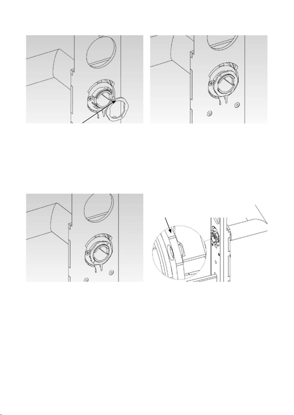
Abb. 2 Abb. 3
Drückerverschluss · Handle fastener piece · Serrure à
loquet · Afsluiting deurkruk · Chiusura della maniglia ·
Cierre del picaporte · Handtagets lock · Håndtagslås ·
Замок рукоятки
Abb. 4 Abb. 5
Drückerverschluss geschlossen · Handle fastener piece
closed · Serrure à loquet fermée · Afsluiting deurkruk
gesloten · Chiusura della maniglia chiusa · Cierre
del picaporte cerrado · Handtagets lock är stängt ·
Håndtagslås lukket · Закрытый замок рукоятки
Drückerverschluss offen · Handle fastener piece open ·
Serrure à loquet ouverte · Afsluiting deurkruk geopend
· Chiusura della maniglia aperta · Cierre del picaporte
abierto · Handtagets lock är öppet · Håndtagslås åben ·
Открытый замок рукоятки
Drückerverschluss · Handle fastener piece ·
Serrure à loquet · Afsluiting deurkruk · Chiusura
della maniglia · Cierre del picaporte · Handtagets
lock · Håndtagslås · Замок рукоятки
Korrekte Position des Drückerverschlusses im geschlossenen Zustand · Correct position for the handle fastener
piece when closed · Position correcte de la serrure à
loquet à l‘état fermé · Correcte positie van de afsluiting van de deurkruk in gesloten toestand · Posizione
corretta della chiusura della maniglia quando chiusa ·
Posición correcta del cierre del picaporte cuando está
cerrado · Korrekt position för handtagets lock i stängt
läge · Korrekt position for håndtagslås i lukket tilstand
· Правильная позиция замка рукоятки в закрытом
состоянии
42
Page 43

Abb. 6
Page 44

Abb. 7
Abb. 8 Abb. 9
≈ 65 mm
≈ 75 mm
44
Page 45

454647
Page 46

Page 47

COMPANY HEADQUARTERS
SimonsVoss Technologies GmbH
Feringastraße 4
85774 Unterföhring
Germany
Tel. +49 89 992280
www.simons-voss.com
ÖSTERREICH
SimonsVoss Technologies GmbH
Kärntner Ring 5-7
1010 Wien
Tel. +43 1 20511601146
SCHWEIZ
Simons Voss Technologies GmbH
Dreikönigstrasse 31a
8002 Zürich
Tel. +41 44 2083241
BENELUX
SimonsVoss Technologies BV
Evert van de Beekstraat 310
1118 CX Schiphol
Tel. +31 20 6541882
NORDISKA LÄNDER
SimonsVoss Technologies AB
Ostermalmstorg 1
Stockholm 114 42
Sverige
Tel. +46 850 25 66 63
РОССИЯ
SimonsVoss Technologies GmbH
РФ, 115191
г. Москва
ул. Б. Тульская д.10 стр.2
russia@simons-voss.com
ITALY
SimonsVoss Technologies GmbH
Via Torino, 2
Milano 20123
Tel. +39 02 72546763
FRANCE
SimonsVoss Technologies SAS
Immeuble „Les Portes des Paris“
1/3 Rue du Rempart
93160 Noisy le Grand
Tél. +33 1 48151480
SPAIN + PORTUGAL
Erkoch Ibérica SL
Avda. Lehendakari Aguirre 38-40
48014 Bilbao
Tel. +34 94 4124900
UNITED KINGDOM
SimonsVoss Technologies Ltd.
1200 Century Way
Thorpe Park · Colton
Leeds · LS15 8ZA
Phone +44 113 2515036
MIDDLE EAST
SimonsVoss Technologies
(Middle East) FZE
P.O.Box 184220
Dubai
UAE
Phone +971 4 8815835
ASIA
SimonsVoss
SecurityTechnologies
(Asia) Pte. Ltd.
151 Lorong Chuan
New Tech Park #05-02
Lobby B
Singapore 556741
Phone +65 62277318
Page 48

© SimonsVoss Technologies GmbH
 Loading...