

Page 1
SmartHandle
Manual
31.07.2019
Page 2

Contents
SmartHandle (Manual)
2 / 136
Contents
1 Intended use ................................................................................................................................................ 7
2 General information ..................................................................................................................................8
3 General safety instructions................................................................................................................... 10
4 Product specific safety notices ........................................................................................................... 14
5 Designs ........................................................................................................................................................ 18
5.1 Prerequisites..................................................................................................................................................... 18
5.2 Profile.................................................................................................................................................................. 20
5.3 mechanical override .................................................................................................................................... 20
5.4 Door thickness................................................................................................................................................ 20
5.5 Spindle .................................................................................................................................................................21
5.6 Fastening.............................................................................................................................................................21
5.7 Backplate width/wide ..................................................................................................................................21
5.8 Centres distance ............................................................................................................................................22
5.8.1 Snap-in .............................................................................................................................................. 22
5.8.2 Conventional fastening system............................................................................................. 22
5.8.3 Conventional fastening system with MO .........................................................................22
5.9 Version.................................................................................................................................................................23
5.10 Handle versions, outside ............................................................................................................................23
5.11 Handle variants for inside ..........................................................................................................................23
5.12 Angle of activation ....................................................................................................................................... 24
5.13 Surface finishes.............................................................................................................................................. 24
5.14 Reader technology ....................................................................................................................................... 24
5.15 Options............................................................................................................................................................... 24
5.15.1 G1 Version.........................................................................................................................................24
5.15.2 G2 Version........................................................................................................................................24
5.15.3 Access control version ...............................................................................................................24
5.15.4 WP version....................................................................................................................................... 25
5.15.5 DP Version .......................................................................................................................................25
5.16 Network (WaveNet).....................................................................................................................................25
5.17 Network (DoorMonitoring)........................................................................................................................25
5.18 SmartHandle without electronics ........................................................................................................ 26
5.19 SKG ...................................................................................................................................................................... 26
5.20 DoorMonitoring (DM).................................................................................................................................. 26
6 Storage ....................................................................................................................................................... 28
Page 3

Contents
SmartHandle (Manual)
3 / 136
7 Installation (manual) ............................................................................................................................ 29
7.1 Snap-in............................................................................................................................................................... 29
7.1.1 Contents of packaging...............................................................................................................29
7.1.2 Tools required ................................................................................................................................29
7.1.3 Installation instructions SnapIn.............................................................................................29
7.1.4 Snap-in............................................................................................................................................. 30
7.1.5 Snap-in WP.....................................................................................................................................33
7.1.6 Snap-in diagrams.........................................................................................................................34
7.1.7 Snap-in on delivery......................................................................................................................35
7.2 Snap-in DoorMonitoring ............................................................................................................................ 35
7.2.1 Contents of packaging...............................................................................................................35
7.2.2 Tools required ............................................................................................................................... 36
7.2.3 Installation instructions SnapIn............................................................................................ 36
7.2.4 Assembly Snap-In Door Monitoring .................................................................................... 37
7.3 Conventional fastening .............................................................................................................................. 43
7.3.1 Contents of packaging...............................................................................................................43
7.3.2 Tools required ............................................................................................................................... 44
7.3.3 Installation instructions ............................................................................................................ 44
7.3.4 Conventional fastening system............................................................................................ 45
7.3.5 Conventional fastening system WP.................................................................................... 47
7.3.6 Diagrams for conventional fastening system................................................................ 50
7.3.7 Storage mode for conventional fastening system ..................................................... 50
7.4 Conventional fastening system WO..................................................................................................... 51
7.4.1 Contents of packaging................................................................................................................51
7.4.2 Tools required .................................................................................................................................51
7.4.3 Installation instructions MO .....................................................................................................51
7.4.4 Conventional fastening system WO................................................................................... 52
7.4.5 Conventional fastening system MO WP...........................................................................55
7.4.6 Diagrams for conventional fastening system................................................................ 58
7.4.7 Storage mode for Conventional Fastening System WO ......................................... 58
7.5 Conventional fastening system SKG................................................................................................... 59
7.5.1 Contents of packaging.............................................................................................................. 59
7.5.2 Tools required ............................................................................................................................... 59
7.5.3 Installation instructions ............................................................................................................ 59
7.5.4 Installation SKG SmartHandle ............................................................................................. 60
7.6 Conventional fastening system for DoorMonitoring....................................................................66
7.6.1 Contents of packaging.............................................................................................................. 66
7.6.2 Tools required ............................................................................................................................... 66
7.6.3 Installation instructions .............................................................................................................67
7.6.4 Installation conventional fastening door monitoring .................................................67
7.7 Additional info: DoorMonitoring sensor lock.....................................................................................74
7.7.1 Sensor lock components..........................................................................................................74
7.7.2 Installation (manual) .................................................................................................................74
Page 4

SmartHandle (Manual)
7.8 Swiss Round MO ............................................................................................................................................76
7.8.1 Contents of packaging...............................................................................................................76
7.8.2 Tools required ................................................................................................................................76
7.8.3 Installation instructions MO ....................................................................................................76
7.8.4 Conventional fastening system, including Swiss Round MO: .................................77
7.8.5 Conventional fastening system, including Swiss Round MO WP........................ 80
7.8.6 Diagrams for conventional fastening system................................................................ 83
7.8.7 Storage mode for SwissRound MO.................................................................................... 83
7.9 Scandinavian Oval .......................................................................................................................................84
7.9.1 Contents of packaging.............................................................................................................. 84
7.9.2 Tools required ............................................................................................................................... 84
7.9.3 Installation instructions ............................................................................................................ 84
7.9.4 Conventional fastening system Scandinavian Oval .................................................. 85
7.9.5 Conventional fastening system for Scandinavian Oval DP.................................... 89
7.9.6 Conventional fastening system for Scandinavian Oval MO ...................................92
7.9.7 Diagrams for Scandinavian Oval......................................................................................... 93
7.9.8 Storage mode for Scandinavian Oval............................................................................... 93
Contents
4 / 136
7.10 SmartHandle Hybrid .................................................................................................................................. 93
8 Programming............................................................................................................................................ 95
8.1 SmartHandle G1 ............................................................................................................................................ 95
8.2 SmartHandle G2 ........................................................................................................................................... 95
8.3 SmartHandle MP ..........................................................................................................................................96
9 Configuration.............................................................................................................................................97
9.1 Impulse length (G2)......................................................................................................................................97
9.2 Access control .................................................................................................................................................97
9.3 Time zone control.........................................................................................................................................98
9.4 Logging unauthorised attempted access events..........................................................................98
9.5 Flip flop ..............................................................................................................................................................98
9.6 No audible battery warnings...................................................................................................................99
9.7 Time switch-over function .......................................................................................................................99
9.8 Permit exception in time zone management (G2) .................................................................... 100
9.9 No audible programming feedback signals.................................................................................... 101
9.10 Card interface (G2)..................................................................................................................................... 101
9.11 Overlay mode (G1) ...................................................................................................................................... 101
9.12 Long release ................................................................................................................................................... 101
9.13 Omron (G1) ..................................................................................................................................................... 101
9.14 Storage mode (G1)..................................................................................................................................... 102
9.15 Freeze mode (G2)....................................................................................................................................... 102
Page 5

Contents
SmartHandle (Manual)
5 / 136
9.16 DoorMonitoring function.......................................................................................................................... 102
9.16.1 Locking device properties: Configuration/Data: DoorMonitoring SmartHandle.
102
9.16.2 Locking device properties: DoorMonitoring status ....................................................103
10 Status messages....................................................................................................................................105
10.1 Battery status ............................................................................................................................................... 105
10.2 Emergency battery active ....................................................................................................................... 105
10.3 Deactivated ................................................................................................................................................... 105
10.4 Emergency release active....................................................................................................................... 106
10.5 Time-limited opening active .................................................................................................................106
10.6 Engaged........................................................................................................................................................... 106
11 Signalling ..................................................................................................................................................107
11.1 Active ................................................................................................................................................................107
11.2 MP........................................................................................................................................................................107
11.3 Hybrid.................................................................................................................................................................107
12 Battery warning (manual) ................................................................................................................. 108
12.1 SmartHandle G1 battery warning (active) .....................................................................................108
12.2 Battery warning SmartHandle G2 (Active).................................................................................... 108
12.3 Battery warning SmartHandle Hybrid ..............................................................................................108
12.4 SmartHandle MP battery warning ..................................................................................................... 109
12.5 Emergency battery storage mode (G1) ............................................................................................ 110
12.6 Procedure for freeze mode (G1) ........................................................................................................... 110
12.7 Procedure for freeze mode (G2)............................................................................................................ 111
13 Battery replacement.............................................................................................................................. 113
13.1 General instructions..................................................................................................................................... 113
13.2 Procedure with SmartHandle WP-SC ...............................................................................................113
13.3 Procedure SmartHandle Hybrid ............................................................................................................ 117
13.4 G2 battery replacement ID medium.................................................................................................... 121
14 Maintenance, cleaning and disinfection......................................................................................... 123
15 Disassembly.............................................................................................................................................124
15.1 Snap-in on delivery .....................................................................................................................................124
15.2 Storage mode for conventional fastening system......................................................................124
15.3 Storage mode for Conventional Fastening System WO..........................................................125
15.4 Storage mode for SwissRound MO ....................................................................................................125
15.5 Storage mode for Scandinavian Oval ...............................................................................................125
Page 6

Contents
SmartHandle (Manual)
6 / 136
15.6 Storage mode for Scandinavian Oval DP ........................................................................................126
15.7 Disassembling DoorMonitoring components ................................................................................126
16 Accessories ...............................................................................................................................................127
16.1 Battery set ....................................................................................................................................................... 127
16.2 British Oval adapter .................................................................................................................................... 127
16.3 Sleeves.............................................................................................................................................................. 127
16.4 Handles............................................................................................................................................................. 127
16.5 Covers ................................................................................................................................................................ 127
17 Technical specifications ......................................................................................................................128
17.1 SmartHandle G1 ...........................................................................................................................................128
17.2 SmartHandle G2 ..........................................................................................................................................128
17.3 SmartHandle Hybrid...................................................................................................................................129
17.4 SmartHandle DoorMonitoring .............................................................................................................. 130
17.5 SmartHandle DoorMonitoring MP ........................................................................................................131
17.6 SmartHandle SKG........................................................................................................................................131
17.7 SmartHandle SKG MP...............................................................................................................................132
18 Declaration of conformity ................................................................................................................... 133
19 Help and other information ................................................................................................................134
Page 7

SmartHandle (Manual)
1 Intended use
Products in the SmartHandle 3062 series are electronic door fittings. With
the aid of an authorised ID medium, the SmartHandle 3062 engages and
the respective door opened.
The corresponding authorisations need to be issued using an electronic
locking plan.
IMPORTANT
The SmartHandle 3062 must be programmed prior to being installed in the
door!
Products in the SmartHandle 3062 range may only be used for locking and
unlocking doors. No other use is permitted.
1. Intended use
7 / 136
Page 8

SmartHandle (Manual)
2 General information
SmartHandle 3062 is an electronic fitting which can be used to open and
close doors.
Electronic fittings in the SmartHandle 3062 range are available in the
following models:
Digital SmartHandle 3062 - Snap-In
Electronic door handle for mounting on doors, designed for a handle
lock with Euro Profile, Swiss Round or British Oval; outer side can only
be operated with an ID medium, inside is always engaged.
Digital SmartHandle 3062 – conventional fastening system
Electronic door handle for conventional installation with mounting
components, designed for a handle lock with Euro Profile, Swiss Round
or British Oval; outer side can only be operated with an ID medium,
inside is always engaged ready to open.
2. General information
8 / 136
Digital SmartHandle 3062 – Conventional fastening with MO
(mechanical override) – for Euro Profile
Electronic door handle for conventional installation on doors with
mounting components; additional options for installing a mechanical
cylinder as a secondary lock; designed for a handle lock with Euro
Profile; outer side can only be operated with an ID medium; inside is
always engaged ready to open.
Digital SmartHandle 3062 – Conventional fastening with MO
(mechanical override) – for Swiss Round
Electronic door handle for conventional mounting on doors with screws;
additional options for installing a mechanical cylinder as a secondary
lock; designed for a handle lock with Swiss Round; outer side can only
be operated with a SimonsVoss transponder, inside is always engaged
ready to open.
Digital SmartHandle 3062 – Conventional fastening - for Scandinavian
Oval
Digital SmartHandle 3062 for conventional installation with mounting
components, designed for a handle lock with Scandinavian Oval; outer
side can only be operated with an ID medium, inside is always engaged
ready to open.
Digital SmartHandle 3062 – Conventional fastening with MO
(mechanical override) – for Scandinavian Oval
Page 9

SmartHandle (Manual)
Digital SmartHandle 3062 for conventional installation with mounting
components, designed for a handle lock with Scandinavian Oval;
additional option for installing a mechanical cylinder as a secondary
lock; outer side can only be operated with an ID medium; inside is
always engaged ready to open.
Handles in the SmartHandle 3062 range can feature the following special
functions:
SKG
For greater security on important doors.
DoorMonitoring
The door's current status can be relayed to an appropriate software
application.
2. General information
9 / 136
Page 10
SmartHandle (Manual)
3 General safety instructions
WARNING
Blocked access
Access through a door may be blocked due to incorrectly fitted and/or incorrectly programmed components. SimonsVoss Technologies GmbH is
not liable for the consequences of blocked access such as access to injured or endangered persons, material damage or other damage!
WARNING
Blocked access through manipulation of the product
3. General safety instructions
10 / 136
If you change the product on your own, malfunctions can occur and access
through a door can be blocked.
Modify the product only when needed and only in the manner described
in the documentation.
CAUTION
Fire hazard posed by batteries
The batteries used may pose a fire or burn hazard if handled incorrectly.
1. Do not try to charge, open, heat or burn the batteries.
2. Do not short-circuit the batteries.
ATTENTION
Damage resulting from electrostatic discharge (ESD)
This product contains electronic components that may be damaged by
electrostatic discharges.
1. Use ESD-compliant working materials (e.g. Grounding strap).
2. Ground yourself before carrying out any work that could bring you into
contact with the electronics. For this purpose, touch earthed metallic
surfaces (e.g. door frames, water pipes or heating valves).
ATTENTION
Damage resulting from liquids
This product contains electronic components that may be damaged by liquids of any kind.
Keep liquids away from the electronics.
Page 11

SmartHandle (Manual)
ATTENTION
Damage resulting from aggressive cleaning agents
The surface of this product may be damaged as a result of the use of unsuitable cleaning agents.
Only use cleaning agents that are suitable for plastic or metal surfaces.
ATTENTION
Damage as a result of mechanical impact
This product contains electronic components that may be damaged by
mechanical impacts of any kind.
3. General safety instructions
11 / 136
1. Avoid touching the electronics.
2. Avoid other mechanical influences on the electronics.
ATTENTION
Damage due to polarity reversal
This product contains electronic components that may be damaged by reverse polarity of the power source.
Do not reverse the polarity of the voltage source (batteries or mains
adapters).
ATTENTION
Failure of operation due to different discharged batteries
This product uses one or more batteries for power supply. The batteries are
discharged at approximately the same rate.
Always replace all batteries at the same time.
ATTENTION
Interference to operation as a result of radio interference
This product may be subject to interference from electromagnetic fields.
Do not place the product directly next to devices that can cause
electromagnetic interference (switching power supplies!).
Page 12
SmartHandle (Manual)
ATTENTION
Communication interference due to metallic surfaces
This product communicates wirelessly. Metallic surfaces can significantly
reduce the reach of the product.
Do not place the product on metallic surfaces.
IMPORTANT
Intended use
SimonsVoss-products are designed exclusively for opening and closing
doors and similar objects.
3. General safety instructions
12 / 136
Do not use SimonsVoss products for any other purposes.
IMPORTANT
Battery contact malfunction due to grease film
When touching batteries, leave a thin film of skin grease on the batteries.
This film deteriorates the contact between the electronics and the batteries.
1. Do not touch the contacts of the new batteries with your hands.
2. Use clean and grease-free gloves.
IMPORTANT
Dispose of the batteries as per local and country-specific regulations.
IMPORTANT
Function error due to poor battery contact
If the contact surface to the battery is too small, then the battery connection may not create a stable connection to the battery.
Only use batteries that are approved by SimonsVoss.
IMPORTANT
Modifications or further technical developments cannot be excluded and
may be implemented without notice.
Page 13

SmartHandle (Manual)
IMPORTANT
This documentation has been compiled based on the best knowledge
available to us. Nevertheless, errors cannot be ruled out. SimonsVoss
Technologies GmbH is not liable in such cases.
IMPORTANT
Should there be differences in the content of other language versions of
this documentation, the German version applies in cases of doubt.
IMPORTANT
3. General safety instructions
13 / 136
You must follow all instructions precisely when connecting and installing
the product. The person installing the system should hand these instructions as well as any maintenance instructions over to the user.
Page 14

SmartHandle (Manual)
4 Product specific safety notices
CAUTION
Combination with SVP-lock
SmartHandle must be combined with a self-locking panic lock to guarantee all functions work correctly. Observe the lock manufacturers' Declaration of Conformity as per EN 179.
ATTENTION
Material damage through drilling error
When you drill, you can cause damage to the door or the product if unsuitable tools are used. The SimonsVoss Technologies GmbH accepts no responsibility for material damage due to drilling errors.
4. Product specific safety notices
14 / 136
Observe safety instructions on drill.
ATTENTION
Malfunction due to moisture
If the exterior of the door is outside or in areas with a high level of humidity
(bathrooms or laundries), then use the WP version. All cable connections
are then drawn into the interior area. The inside of the WP version is not
protected against moisture.
1. Always use a WP version where the outside could come into contact
with moisture.
2. Ensure that no moisture can reach the inside of the door.
ATTENTION
Damage to the cables/cable connections
If you pull the cables, the cable connections or the cable itself could be
damaged.
1. Do not pull the cables.
2. Disengage and separate the plug connectors carefully.
Page 15

SmartHandle (Manual)
ATTENTION
Loss of the precise guidance of the handle
It may be difficult to install on mortise locks with a retaining nut.
Do not mechanically alter the locking nut. The handle would then lose
its precise guidance.
ATTENTION
Freeze mode due to separate storage
If you store the housing halves separately for a longer period of time (more
than a week), SmartHandle may switch to freeze mode.
4. Product specific safety notices
15 / 136
Only separate the two halves of SmartHandle when installing it.
ATTENTION
Mechanical damage to the LockNode
If the cover is fitted or removed, the LockNode can be damaged.
1. Fit or remove the cover carefully.
2. In removal, be aware of the slit in the cover.
ATTENTION
Mechanical damage to the SmartHandle due to obstructions
If the handle can hit the wall or other objects due to the installation location, it can become deformed or break off.
In such situations, use a suitable door-stopper.
ATTENTION
Mechanical damage to the handle through misuse as door-opener
Some doors are very heavy and solidly constructed. The handle is not suitable for opening such doors.
Make suitable door openers available (suitable handles) to avoid
misuse of the knob.
Page 16

SmartHandle (Manual)
IMPORTANT
Specialist knowledge in door mechanics, door approvals, electronic system
installation and the use of SimonsVoss software is required to install the
system and put it into operation. Only trained specialists may install the
system.
IMPORTANT
Damage from unsuitable tool
Only use the SimonsVossfitting tool for assembly and battery changes.
4. Product specific safety notices
16 / 136
IMPORTANT
Faulty orientation before fitting the conventional MO-version
The fastening holes and the spindle must be vertically aligned; otherwise,
you may not be able to install the fitting. Use the drill-hole template.
IMPORTANT
Effect of theSmartHandle 3062
The SmartHandle 3062 affects only the latch of the mortice lock.
IMPORTANT
Programming with obsolete LSM version
New components can only be programmed with the current version of
LSM.
IMPORTANT
Stiffness of the SmartHandle due to stiff mortice lock
If the mortice lock is stiff, the SmartHandle will also be stiff.
Check that the mortice lock is free-moving.
Page 17

SmartHandle (Manual)
IMPORTANT
Fitting error or incorrect order
If you make a mistake in measuring the door and order a SmartHandle, the
SmartHandle will not fit.
Check the dimensions of the door again before ordering.
4. Product specific safety notices
17 / 136
Page 18
Interior side Exterior side
SmartHandle (Manual)
5 Designs
The following section describes the different individual versions or options
available for SmartHandle
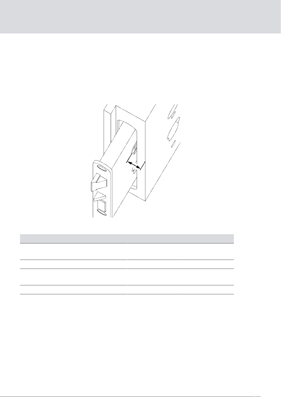
5.1 Prerequisites
These distances depend on the version of the door.
Distance lock nut
front face (exterior
side) to exterior
side door leaf
5. Designs
18 / 136
The SmartHandle 3062 is suitable for the following distances:
Version Door thickness S Door thickness M Door thickness L
conventional/
SnapIn
RMO/RRMO min. 1 mm min. 1 mm min. 1mm
E1/SKG
SO min. 1 mm min. 1 mm min. 1 mm
min. 4 mm min. 4 mm min. 4 mm
No minimum thickness
No minimum thickness
No minimum thickness
Page 19
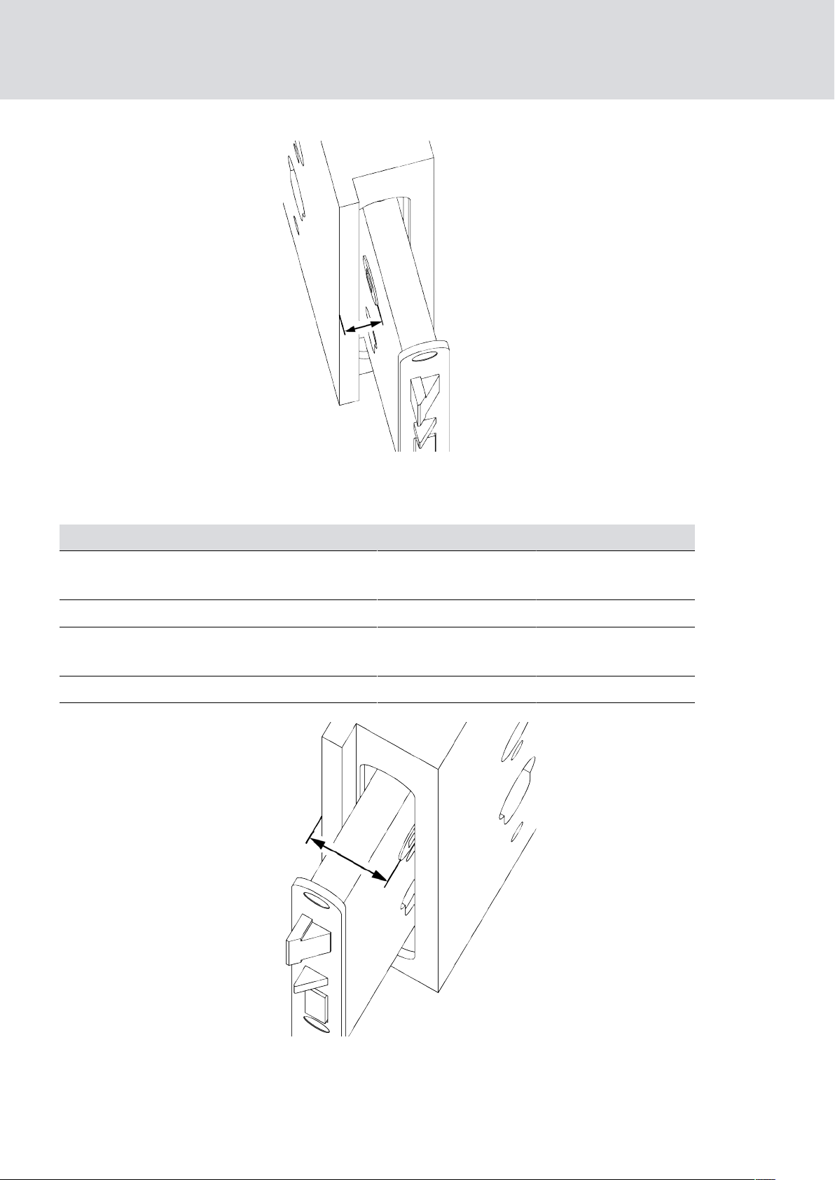
Interior side
Exterior side
Interior side Exterior side
SmartHandle (Manual)
Distance lock nut
front face (interior
side) to interior side
door leaf
5. Designs
19 / 136
The SmartHandle 3062 is suitable for the following distances: of at least 5
mm.
Version Door thickness S Door thickness M Door thickness L
conventional/
SnapIn
min. 5 mm min. 5 mm min. 5 mm
RMO/RRMO min. 1 mm min. 1 mm min. 1 mm
E1/SKG
No minimum thickness
No minimum thickness
No minimum thickness
SO min. 2 mm min. 2 mm min. 2 mm
Distance lock nut
front face (exterior
side) to interior side
door leaf
The SmartHandle 3062 is suitable for the following distances depending
on the version:
Page 20

SmartHandle (Manual)
Version Door thickness S Door thickness M Door thickness L
5. Designs
20 / 136
conventional/
SnapIn
RMO/RRMO max. 37 mm max. 57 mm max. 77 mm
E1/SKG max. 38 mm max. 58 mm max. 78 mm
SO max. 38 mm max. 58 mm max. 78 mm
max. 41 mm max. 61 mm max. 81 mm
5.2 Profile
SmartHandle 3062 is available for the following mortise lock profiles:
Euro Profile Cylinder
Swiss Round
British Oval
Scandinavian Oval
5.3 mechanical override
It is usually also possible to fit a mechanical cylinder. This enables you to
open the door without using the electronics and open the door with a
mechanical key. This allows the fire service to lock to the door, for example.
You have the option of a cover with a blank design, where the cylinder is
completely covered, or a cover with a cut-out on one side or on both sides.
5.4 Door thickness
can be ordered in different door thickness widths:
Euro Profile:
S 39 – 60 mm
M 59 – 80 mm
L 79 – 100 mm
Swiss Round:
S 33 – 54 mm
M 53 – 74 mm
L 73 – 94 mm
Scandinavian Oval with drilling protection (SO.DP):
S 30 – 51 mm
M 50 – 71 mm
L 70 – 91 mm
Page 21

SmartHandle (Manual)
Conventional fastening system SKG:
S 32 – 50 mm
M 50 – 70 mm
L 70 – 90 mm
5.5 Spindle
The following spindle sizes are available:
7 mm
8 mm
F8 (for fire retardant doors)
8.5 mm
5. Designs
21 / 136
9mm (for fire retardant doors)
10 mm
A sleeve is available for the 8.5mm and 10mm solutions. The 10mm
sleeve is part of the supply; order the 8.5mm one if required. See
Accessories to order. The 8mm spindle serves as a basis for the solution;
8mm to 8.5mm and 8mm to 10mm sleeve.
The SmartHandle designs with F8 and 9mm spindles are approved for use
in fire retardant doors:
F8 (8 mm) spindle as per EN1906 or EN1634
9 mm spindle as per DIN 18273
5.6 Fastening
Three different types of fastening system available:
Snap-in
Conventional fastening system
Conventional fastening system with MO (blank and cut-out)
Snap-in does not require any additional drill holes in the door as it uses the
existing standard holes for mounting.
With the conventional fastening system, it is possible to also install a
mechanical cylinder to override the electronics.
5.7 Backplate width/wide
The following backplate widths are available for the inlay:
Narrow plate, 41 mm
Wide plate, 53 mm
Page 22
SmartHandle (Manual)
SmartHandles with the DP or SKG option are somewhat larger due to the
additional mounting plate:
Narrow plate, 47 mm
Wide plate, 59 mm
5.8 Centres distance
The following centres distances are available for the different fastening
types:
5.8.1 Snap-in
70 mm
5. Designs
22 / 136
72 mm
75 mm
78 mm
85 mm
88 mm
92 mm
94 mm
5.8.2 Conventional fastening system
The centres distance is an unimportant factor in the SmartHandle layout. It
is indicated with the figures '00.' Centres distances between 70 and
98.5mm can be covered as a general rule, irrespective of the lock case.
The following diagram or the following dimensions apply:
Mortise locks with centre distances between 46mm to 98.5mm (greater
also possible; check diagram in such cases) can be used if it is possible to
drill the two holes through the door without damaging the lock.
5.8.3 Conventional fastening system with MO
The following distances are available:
Page 23

SmartHandle (Manual)
Euro Profile Swiss Round
72 mm ×
74 mm ×
75 mm ×
78 mm × ×
85 mm ×
88 mm ×
90 mm ×
92 mm × ×
94 mm ×
5. Designs
23 / 136
5.9 Version
SmartHandle 3062 is available in a version with a reader on one side. The
inside handle is always mechanically engaged, so that the door can always
be operated or opened from the inside without a medium in the event of an
emergency.
5.10 Handle versions, outside
Different designs are available as handle variants:
L-shaped U-shape
mitred mitred
rounded, curved rounded, curved
rounded, curved, offset rounded, curved, offset
mitred, offset mitred, offset
round, curved with anti-bacterial
coating
round, curved with anti-bacterial
coating
5.11 Handle variants for inside
Different designs are available as handle variants:
L-shaped U-shape
mitred mitred
rounded, curved rounded, curved
rounded, curved, offset rounded, curved, offset
mitred, offset mitred, offset
round, curved with anti-bacterial
coating
A thumb-turn is also available for the SKG variant.
round, curved with anti-bacterial
coating
Page 24

SmartHandle (Manual)
5.12 Angle of activation
The SmartHandle 3062 is suitable for mortise locks with an angle of
activation of up to 38 degrees.
5.13 Surface finishes
Surface finishes are available in brushed stainless steel and brushed brass
colours.
5.14 Reader technology
You can choose between active technology and MIFARE® technology for
reader systems. SmartHandle 3062 – SC can be activated using both
active transponders and MIFARE® cards. SmartHandle 3062 – SC can only
be supplied in combination with G2 protocols. The following MIFARE
products may be used:
5. Designs
24 / 136
®
MIFARE® Classic (1k and 4k smart cards/tags)
MIFARE® PLUS S (2k and 4k smart cards/tags)
MIFARE® PLUS X (2k and 4k smart cards/tags)
MIFARE® DESFire EV1 (2k, 4k and 8k smart cards/tags)
5.15 Options
5.15.1 G1 Version
G1 products are supported in this version. Existing G1 locking systems can
be upgraded with SmartHandle or SmartHandle can be integrated into
new G1 systems. Up to 8,000 different transponders can be managed. LSM
3.0 or higher and a programming device (Smart CD type or newer) are
required to use this solution.
5.15.2 G2 Version
G2 products are supported in this version. Existing G2 locking systems can
be upgraded with SmartHandle or SmartHandle can be integrated into
new G2 systems. Up to 64,000 different transponders or 64,000 different
smart cards (Hybrid or MP variants) can be managed in these systems.
See the 'G2 Protocols' manual for more detailed information.
5.15.3 Access control version
Design is similar to standard version but with access event logging and time
zone control.
Page 25
SmartHandle (Manual)
Access event logging
SmartHandle logs up to 3,000 (G1) or up to 3,600 (G2) of the most recent
access events with the date, time and transponder ID (TID). The data can
be read via the network or using the programming device at any time.
Time zone control
SmartHandle can be programmed in such a way that authorised
transponders and smart cards/smart tags (G2) are only authorised for
access at specific times. There are 16,000 (G1) or 64,000 (G2) time zone
schedules available per locking system within the different time zone
schedules and 5+1 (G1) or 100+1 (G2) different time zone groups available
per locking device.
5. Designs
25 / 136
5.15.4 WP version
The WP version has been specially developed for the exterior shell of
buildings. This variant should always be used when the outer surface may
come into contact with damp. SmartHandle must not come into contact
with damp through the door or in indoor areas.
5.15.5 DP Version
Version with extra protection against levering open.
5.16 Network (WaveNet)
You can equip SmartHandle 3062 with a network node at any time. You do
not need to exchange any components to do so. Simply plug the network
node circuit board into its designated slot.
There is a special waterproof version of the network circuit board for use
outdoors. You require a WP network node for a WP SmartHandle. If you
use the WP version, you'll find the slot for the network node on the inner
side.
5.17 Network (DoorMonitoring)
The LockNodes are already permanently integrated into SmartHandles
with the DoorMonitoring function and cannot be replaced.
Page 26

SmartHandle (Manual)
5.18 SmartHandle without electronics
A SmartHandle 3062 without electronics can be supplied on request for
design reasons. The spindle is always continuous in such handles, so that
the door can always be operated or opened from the inside or outside
without a medium such as a transponder. The MO variant must be selected
for locking the door, which can be locked using an additional cylinder in this
variant.
5.19 SKG
SmartHandle 3062 with SKG certification (SKG**) also satisfies high
security requirements. This version of SmartHandle 3062 guarantees that it
will remain fully functional for the long term even under extreme conditions
and provide optimum protection against break-ins or tampering.
5. Designs
26 / 136
5.20 DoorMonitoring (DM)
with DoorMonitoring (DM) is an electronic door fitting with integrated door
monitoring. The integrated door monitoring system in the DM Cylinder is
fitted without any wiring to the door.
SmartHandles with the DoorMonitoring function may only be used in
combination with self-locking panic locks. The DoorMonitoring
SmartHandle with external "sensor lock" sensors can also be used as a MO
version.
Sensors inside the DM SmartHandle 3062 monitor the door opening status.
The DM SmartHandle 3062 logs access events (access lists) and monitors
door status and changes to door status (open, closed, locked, securely
locked, manipulation attempt and forced entry).
The following door statuses are logged:
Door open/closed
Door unlocked/securely locked
Alarm
These door statuses can be transmitted to LSM via the WaveNet network,
where they can be displayed, so that the user can see the door status
easily.
The LSM software allows you to define events which trigger a definable,
time-dependent response, such as a pop-up window with a warning or an
email, when the status of a locking device changes.
Alarms can be transmitted to third-party software in LSM Basic (from
Version 3.3).
Page 27

SmartHandle (Manual)
All changes are logged in the access list, including the transponder ID, date
and time, which the locking system operator or a security officer can then
upload and evaluate if necessary.
5. Designs
27 / 136
Page 28

SmartHandle (Manual)
6 Storage
ATTENTION
Freeze mode due to separate storage
If you store the housing halves separately for a longer period of time (more
than a week), SmartHandle may switch to freeze mode.
Only separate the two halves of SmartHandle when installing it.
Storage mode
SmartHandle is screwed together in its box when delivered. The two
housing halves are firmly joined together. You can programme
SmartHandle directly as it is in the box.
6. Storage
28 / 136
After initial programming
Leave the housing halves screwed together after initial programming.
Installation
You need to separate the two housing halves to install SmartHandle. Do
not separate the two halves until just before you install it.
Page 29

SmartHandle (Manual)
7 Installation (manual)
Some variants are supplied screwed into temporary spacer sleeves, so that
the SmartHandles can be programmed in the packaging. This will ensure
that the metal surfaces touch. Contact needs to be established in this way
to programme SmartHandle.
Temporary spacer sleeves are used to secure SmartHandles during
transport and are not needed to operate SmartHandles.
The plastic screws are used to secure SmartHandles during transport
and must not be used for installation.
7.1 Snap-in
7. Installation (manual)
29 / 136
7.1.1 Contents of packaging
2 x inlays
2 x covers
1 x outer fitting
1 x inside fitting
1 x outer fitting, including lock ring
1 x inside handle for inside fitting (including hexagon screw)
1 x mounting screw
1 x profile cylinder inlay (in versions for fire retardant doors only)
1 x quick start guide
1 x installation tool for inlay
7.1.2 Tools required
The following tools are required for installing SmartHandle 3062 and are
not included in the supplied package:
Allen key (3mm) to fit handle
Cross-tip screwdriver type PH2 (battery screwdriver recommended)
7.1.3 Installation instructions SnapIn
Batteries are already installed when the product is delivered!
When installing the electronic SmartHandle 3062, ensure that there are
no sources of low-frequency interference in the surrounding area.
SmartHandle 3062 must be fitted, so that it is flush with the door. You
must install the product as specified to ensure that it is structurally
stable and will have a long service life.
Page 30
SmartHandle (Manual)
You must not strike parts of SmartHandle 3062 during installation.
The two inlays in the cover are locked into position with a clip
mechanism. These may only be removed using the SimonsVoss
installation tool.
In the case of fire retardant doors, you must ensure that the supplied
profile cylinder inlay is pressed against the snap-in mechanism in the
inside fitting.
No water or moisture must penetrate the door or reach the inner side.
Always use the WP version for moisture.
Programme SmartHandle 3062 before installing.
SmartHandle 3062 may be difficult to fit in mortise locks with a
retaining nut. You must not alter the retaining nut in any way, using a file,
for example; otherwise, the handle's guide piece will no longer fit
accurately.
7. Installation (manual)
30 / 136
When installing SmartHandle, you must ensure that the cable does not
get caught or fitted too tightly to the door.
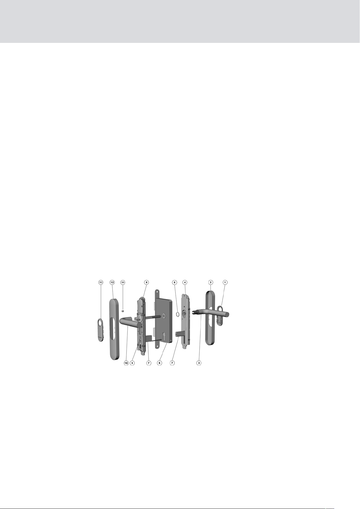
7.1.4 Snap-in
Key:
1. Inlay
2. Inlay
3. Outside handle
4. Outer fitting
5. handle fastener piece
6. Door lock (not included in the scope of supply)
7. Snap-in mechanism
8. Inside fitting
9. Screw
Page 31

SmartHandle (Manual)
10. Inside handle
11. Inside hexagon screw
12. Inlay
13. Inlay
Installation
1. Optional: handles, escutcheons, fittings and other door furniture fitted
to the door are to be removed.
2. Optional: Fasten mortise lock into the door
3. SmartHandle is partly assembled when delivered; see Disassembly.
4. The inlay cannot be fitted on some handles, such as offset handles,
when they are already installed. Push the inlay onto the outer handle
with the logo facing outwards in such cases. You can do this with most
handles.
7. Installation (manual)
31 / 136
5. Push inlay (1) onto the outer handle (3). Depending on the handle
model, it may not be possible to fit it once the handle is installed.
6. Insert outer handle (3) horizontally into the outer fitting (4), placing it in
the direction that you require, depending on whether it is a DIN left-hand
or right-hand door.
7. Place handle fastener piece (5) into position (see Diagrams 2 and 3).
8. Hold the outside handle (3) and use the spanner to rotate the fastener
piece (5) about 75° to the right until it fits into position (Diagrams 4 and
5). If you do not fit it correctly, the handle may come loose again.
9. Optional: In a lock with an 8.5 mm or 10 mm spindle, push the corresponding sleeve (8 mm --> 8.5 mm [not included in the supply package]
or 8 mm --> 10 mm) through the retainer opening in the mortise lock
from the inside.
10. Push the 3-pole inside fitting cable into the snap-in mechanism (7). This
protects it from external impact during installation (Diagram 6).
11. The inside fitting (8) is mounted onto the inner surface of the door. The
inside fitting (8) is fastened to the door by sliding the spindle through
the retainer slot and the snap-in mechanism through the mortise lock
(6) cylinder opening at the same time.
12. Push the inside fitting (8) until it is flush with the door.
13. Remove the cables from the snap-in mechanism (7), so that they hang
freely out of the door and are not damaged (Diagram 7).
Page 32

SmartHandle (Manual)
14. The outer fitting (4) is mounted from the outer side of the door. Push
the spindle slot in the outer fitting (4) onto the spindle while pushing the
snap-in mechanism (7) on the outer fitting (4) into the snap-in (7) on
the inside fitting (8).
15. Push on outer fitting (4) until it is about 1cm from the door.
16. Push the inside fitting 3-pole cable through the elongated hole in the
outer fitting. Do not pull on the cable while doing so (Diagram 8).
17. Connect the 3-pole cable from the inside fitting to the 3-pole cable
from the outer fitting. This cable can only be inserted in one direction.
Do not pull on the cables while doing so; just carefully secure the plug-in
connection into position.
18. Optional: Connect the 2-pole cable from the LockNode to the 2-pole
cable from the inside fitting.
7. Installation (manual)
32 / 136
19. The 2-pole cable from the outer fitting can hang freely, but must not get
caught when the outer cover (1) is fitted. Do not pull on the cable.
20.Press outer and inside fittings together, so that they are both flush
against the door.
21. Push mounting screw (9) through the snap-in mechanism (7) from the
inner side of the door and tighten by hand, using about 5-7Nm.
22. Check that the outer handle (3) can turn easily; if it does not, there may
be a problem with the lock or the handle may have been fitted incorrectly. In case of doubt, disassemble components and start again from
Step 7. Depending on the handle model, it may not be possible to fit it
once the handle is installed.
23. Push inside handle (10) onto the inner fitting (8) fastening flange until it
will go no further.
24.Tighten the hexagon screw (11) on the inside handle (10) by hand, so
that it is flush with the handle.
25. Push the cover (12) over the inside handle (10).
26.Carefully push the inlay (13) through the opening in the inside cover (12).
27. Push the cover (12) onto the inside fitting (8), so that it is flush with the
door. The cover is not symmetrical; look carefully at the marking to ensure correct positioning (Diagram 10).
28.Click the inlay (13) carefully into the cover (12).
29.Push the cover (1) over the outside handle (3).
30.Carefully push the inlay (1) through the opening in the outside cover (2).
31. Push the cover (2) onto the outer fitting (4), so that it is flush with the
door. The cover is not symmetrical; look carefully at the marking to ensure correct positioning (Diagram 10).
32. Push the inlay (1) over the handle (3) and click it into place in the cover.
Page 33

SmartHandle (Manual)
7.1.5 Snap-in WP
1. Optional: handles, escutcheons, fittings and other door furniture fitted
to the door are to be removed.
2. Optional: Fasten mortise lock into the door
3. SmartHandle is partly assembled when delivered; see Disassembly.
4. The inlay cannot be fitted on some handles, such as offset handles,
when they are already installed. Push the inlay onto the outer handle
with the logo facing outwards in such cases. You can do this with most
handles.
5. Push inlay (1) onto the outer handle (3).
6. Insert outer handle (3) horizontally into the outer fitting (4), placing it in
the direction that you require, depending on whether it is a DIN left-hand
or right-hand door.
7. Installation (manual)
33 / 136
7. Place handle fastener piece (5) into position (see Diagrams 2 and 3).
8. Hold the outside handle (3) and use the spanner to rotate the fastener
piece (5) about 75° to the right until it fits into position (Diagrams 4 and
5). If you do not fit it correctly, the handle may come loose again.
9. Optional: In a lock with an 8.5 mm or 10 mm spindle, push the corresponding sleeve (8 mm --> 8.5 mm [not included in the supply package]
or 8 mm --> 10 mm) through the retainer opening in the mortise lock
from the inside. The 8.5mm sleeve is not included in the supplied package.
10. Push the cable from the outer fitting through the profile cylinder/Swiss
Round/British Oval opening in the mortise lock (6) from the outer side.
11. Then insert the inside fitting (8) by pushing the spindle through the retainer slot at the same time. Also push the snap-in mechanism through
the cylinder opening in the mortise lock (6) and through the door, so
that it is flush with the door. Ensure you do not catch or buckle the cable
while doing so.
12. Then push the outer fitting (4) spindle slot onto the inside fitting spindle
while pushing the snap-in mechanism (7) on the outside fitting into the
snap-mechanism (7) on the inside fitting, so that the fitting is flush with
the door.
13. Press outer and inside fittings together, so that they are both flush
against the door.
14. Check that the outer handle (3) can turn easily; if it does not, there may
be a problem with the mortise lock (6) or the handle may have been fitted incorrectly. In case of doubt, disassemble components and start
again from Step 7.
Page 34

SmartHandle (Manual)
15. Push mounting screw (9) through the snap-in mechanism (7) from the
inner side of the door and tighten by hand, using about 5-7Nm (see diagram).
16. Connect the 2-pole cable from the outer fitting to the 2-pole cable from
the inside fitting. This cable can only be inserted in one direction. Do not
pull on the cables while doing so; just carefully secure the plug-in connection into position.
17. The 2-pole cable from the inside fitting can hang freely, but must not
get caught or buckled during installation. Do not pull on the cable. The
second cable is optionally used to connect the WaveNet circuit board.
18. Optional: Connect the 2-pole cable from the LockNode to the 2-pole
cable from the inside fitting.
19. Push inlay (13) onto the inside handle (10). Depending on the handle
model, it may not be possible to fit it once the handle is installed.
7. Installation (manual)
34 / 136
20.Push inside handle (10) onto the inner fitting (8) fastening flange until it
will go no further.
21. Tighten the hexagon screw (11) on the inside handle (10) firmly by hand,
using about 5-7 Nm.
22. Push the cover (12) over the inside handle (10).
23. Carefully push the inlay (13) through the opening in the inside cover (12).
24.Push cover (12) over the inside fitting (8), so that it is flush against the
door. The cover is not symmetric, so please observe markings to place in
correct position (Diagram 10).
25. Click the inlay (13) carefully into the cover (12).
26.Push the cover (2) over the outside handle (3).
27. Carefully push the inlay (1) through the opening in the outside cover (2).
28.Push cover (2) over the inside fitting (4), so that it is flush against the
door. The cover is not symmetric, so please observe markings to place in
correct position (Diagram: Step 10).
29.Click the inlay (1) carefully into the cover (2).
7.1.6 Snap-in diagrams
Figure 2:
Handle fastener piece
Figure 3:
Handle fastener piece open
Page 35

SmartHandle (Manual)
Figure 4:
Handle fastener piece closed
Figure 6: Figure 7:
7. Installation (manual)
35 / 136
Figure 5:
Fastener piece - correct position for
the handle fastener piece when
closed
Tab.1:
Figure 8: Figure 9:
Figure 10:
7.1.7 Snap-in on delivery
1. Disconnect the 3-pole cable from the inside fitting to the 3-pole cable
2. Undo mounting screw (9) in the inside fitting (8) about 1cm.
3. Use a soft object to knock on the mounting screw (9) to release the
4. Undo mounting screw (9) fully.
5. Hold the inside and outer fittings firmly while carefully pulling them
Diagrams showing installation
from the outer fitting. If necessary, also disconnect the LockNode cable
from the inside fitting.
tension in the snap-in mechanism (7).
away from one another horizontally.
Fitted to the door:
IMPORTANT
General instructions: Depending on the handle model, it may not be possible to remove the inlay immediately. In such a case, push the inlay
through the opening in the cover and remove the cover. The inlay remains
on the handle and cannot be removed until the handle is dismounted.
Follow the same steps as for installation but in reverse order.
7.2 Snap-in DoorMonitoring
7.2.1 Contents of packaging
2 x inlays
2 x covers
Page 36

SmartHandle (Manual)
1 x outer fitting
1 x inside fitting
1 x outer handle (including lock ring)
1 x inside handle (including hexagon screw)
1 x mounting screw
1 x fire retardant inlay (in versions for fire retardant doors only)
1 x installation tool for inlay
1 x fastening screw sensor
1 x bolt sensor
1 x Installation tool for bolt sensor
7. Installation (manual)
36 / 136
1 x Installation tool for four-wire cable
1x extension cable (2-pole)
(2x for L version for doors over than 79 mm
thickness)
1 x quick start guide
7.2.2 Tools required
The following tools are required for installation are not included in the
delivery:
Allen key (3mm) to fit handle.
Cross-tip screwdriver type PH2 to fit mounting screw (battery-operated
screwdriver recommended).
19mm spanner for installing the handle fastener piece.
7.2.3 Installation instructions SnapIn
Batteries are already installed when the product is delivered!
When installing the electronic SmartHandle 3062, ensure that there are
no sources of low-frequency interference in the surrounding area.
SmartHandle 3062 must be fitted, so that it is flush with the door. You
must install the product as specified to ensure that it is structurally
stable and will have a long service life.
You must not strike parts of SmartHandle 3062 during installation.
The two inlays in the cover are locked into position with a clip
mechanism. These may only be removed using the SimonsVoss
installation tool.
Page 37

SmartHandle (Manual)
In the case of fire retardant doors, you must ensure that the supplied
profile cylinder inlay is pressed against the snap-in mechanism in the
inside fitting.
No water or moisture must penetrate the door or reach the inner side.
Always use the WP version for moisture.
Programme SmartHandle 3062 before installing.
SmartHandle 3062 may be difficult to fit in mortise locks with a
retaining nut. You must not alter the retaining nut in any way, using a file,
for example; otherwise, the handle's guide piece will no longer fit
accurately.
When installing SmartHandle, you must ensure that the cable does not
get caught or fitted too tightly to the door.
7. Installation (manual)
37 / 136
7.2.4 Assembly Snap-In Door Monitoring
These installation instructions are designed for a standard door with a selflocking panic lock (SLP lock) already fitted. Old fittings must be fully
removed before SmartHandle 3062 SmartHandle is installed.
IMPORTANT
To ensure full functionality, SmartHandle must always be used in combination with a self-locking panic lock (SLP lock). Please observe conformity
declarations of lock manufacturers in accordance with EN 179!
All steps must be completed in order after one another to ensure correct
installation.
Page 38

SmartHandle (Manual)
7.2.4.1 Components
7. Installation (manual)
38 / 136
SmartHandle components (SnapIn)
1 Inlay
2 Outer cover
3 Outside handle
4 Outer fitting
5 Handle fastener piece
6 Lock (not included)
7 Inside fitting
8 Inside handle
9 Headless screw for inside handle
10 Inside cover
11 Inlay
Door Monitoring components (SnapIn)
A Installation tool for cable
B Fastening screw sensor
Page 39

INSTALLATION
LOCKED
SmartHandle (Manual)
C Bolt sensor
D Installation tool for bolt sensor
7.2.4.2 Step 1: Installing the fastening screw sensor
IMPORTANT
The fastening screw sensor may not be in locked final position during installation. The fastening screw sensor must be in the displayed "INSTALLATION" position; otherwise ("LOCKED") the outer ring must be pushed
back carefully so that the spring mechanism is tensioned.
7. Installation (manual)
39 / 136
1. Insert the end of the fastening screw sensor cable (B) (with plug) into
the sensor screw drill hole.
2. Use a suitable tool (e.g. tweezers) to guide the plug out of the profile
cylinder opening on the inner side.
3. Insert fastening screw sensor into the sensor screw hole until it will go
no further.
9 A spring mechanism holds the fastening screw sensor in place in the
door lock.
7.2.4.3 Step 2: Bolt sensor installation
Preparing the bolt sensor
The bolt sensor (C) must be attached to the installation tool (D) as shown
in the following image in preparation for installation:
Page 40

SmartHandle (Manual)
The bolt sensor cone may need to be moved, depending on the door lock
used. You will find the correct position online at
most cases, the cone can remain in the pre-set "Position 1".
Follow the steps below to move the cone:
1. Ensure that the bolt sensor (C) is placed firmly on the installation tool
(D).
7. Installation (manual)
40 / 136
www.simons-voss.com
. In
2. Simply release the outer ring segment from point X (see image above)
by turning in the direction of the arrow.
3. Move the cone parallel to the axial direction to release it.
4. Pull the cone into the required position.
9 You will find the correct position online at
9 Each bar corresponds to a position. The first bar corresponds to the
non-approved zero position. The image shows the cone at Position 1.
5. Turn the ring segment back to its original position until you hear it snap
back into position.
Determining the direction of installation
The door lock must be in the unbolted position when it is installed.
The square opening in the bolt sensor must always point to the right
towards the door hinges when the bolt sensor is fitted. This determines
whether the bolt sensor needs to be fitted from the inner or outer side of
the door.
Fitting the bolt sensor from the inner side
www.simons-voss.com
.
1. Carefully release cable from the bolt sensor (C) cable duct to guide the
plug out onto the inner side.
2. Push the bolt sensor into the profile cylinder opening via the installation
tool (D) until it stops.
9 The square opening in the bolt sensor must always point to the right
towards the door hinges.
3. Rotate bolt sensor 90º, so that the bolt sensor opening points downwards.
Page 41

75°
1
2
4
-45°
3
SmartHandle (Manual)
4. Pull the installation tool to remove.
9 The bolt sensor remains in the lock. The rectangular opening in the
bolt sensor faces downwards.
Fitting the bolt sensor from the outer side
1. Push the bolt sensor (C) into the profile cylinder opening via the installation tool (D) until it stops.
9 The square opening in the bolt sensor must always point to the right
towards the door hinges.
2. Rotate bolt sensor 90º, so that the bolt sensor opening points downwards.
3. Pull the installation tool to remove.
9 The bolt sensor remains in the lock. The rectangular opening in the
bolt sensor faces downwards.
7. Installation (manual)
41 / 136
7.2.4.4 Step 3: Preparing to install the outer fitting
1. Place outer cover (2) loosely onto the outer fitting (4). Notice that the
outer cover can only be placed onto the fitting in one direction.
9 The outer cover is positioned flush on the outer fitting but without
fastening it.
2. Push inlay (1) onto the outer handle (3) from the short side. Ensure that
the black side of the inlay is turned towards the door.
3. Insert outer fitting horizontally into the outer fitting in the direction that
you require (DIN left or DIN right).
9 The outer handle is placed in the outer fitting without being
fastened.
4. Position handle fastener piece (5) on the side which will later face the
door, as in the diagram below, and fasten with a spanner in a clockwise
direction (about 75º until you feel resistance).
9
9 The outer handle is now firmly attached to the outer fitting and
cannot be removed from the outside when in use.
5. Check the handle mechanism to ensure it opens easily.
9 The outer handle must return to its home position of its own accord.
Repeat the procedure described in this section if the outer handle
should catch and not open correctly.
IMPORTANT
For easier installation, the cover can also be pushed over the inlay later in
chapter "
Step 6: Fastening the covers [}43]
".
Page 42

SmartHandle (Manual)
7.2.4.5 Step 4: Installation of fittings
1. Position installation tool through the profile cylinder opening in the door
lock, so that the plug remains on the outer side.
2. Push the inside fitting spindle through the retainer slot in the door's
mortise lock, so that the fitting is flush with the door.
3. Cables for fastening screw and bolt buttons and the installation tool
must be fed through the snap-in mechanism to the inner side.
9 The inside fitting is now firmly placed flat against the door. The
cables and installation tool run downwards on the inside of the door.
If a two-wire cable should be too short, a extension/adapter cable
can be used.
4. Use the installation tool to connect four-wire cables from the outer fitting.
7. Installation (manual)
42 / 136
5. Push plug out horizontally, directly beneath the snap-in mechanism,
and to the inner side. The outer fitting must be joined together with the
inside fitting at the same time by inserting the outer fitting bolt into the
inner fitting's snap-in shaft.
IMPORTANT
Ensure that no cabling gets caught or broken.
6. Screw inside fitting together with the outer fitting from the inside. Ensure
that the fitting is positioned in parallel to the door.
9 Inside and outer fitting are now firmly joined together flat against the
door.
7. Connect cables. The two two-pole cables and the four-pole cable are
to be properly connected to one another.
The two-pole cables can be
connected to one another as desired.
8. Lay cables in such a way that the cover can be easily fitted. Make sure
that you do not crush the cables.
7.2.4.6 Step 5: Installing the inside handle
1. Position the inside cover (11) on the inside fitting without fastening it.
Notice that the cover can only be placed onto the fitting in one direction.
9 The cover is positioned flush on the inside fitting but without
fastening it.
2. Push inlay (11) onto the inside handle retainer. Ensure that the black side
of the inlay is turned towards the door.
Page 43

SmartHandle (Manual)
3. Insert inner handle horizontally into the inside fitting in the direction you
require (DIN left or DIN right).
9 The inside handle is placed in the inside fitting without being
fastened.
4. Tighten the headless screw to fasten inside handle.
9 The inner door handle is now firmly linked to the SmartHandle.
5. Check the handle mechanism to ensure it opens easily.
9 Repeat the procedure described in this section if the handle should
catch or jam!
IMPORTANT
For easier installation, in most cases the cover can be pushed over the inlay
later in chapter "
Step 6: Fastening the covers [}43]
7. Installation (manual)
43 / 136
".
7.2.4.7 Step 6: Fastening the covers
Outer and inside covers are mounted in the same way:
1. Carefully press cover onto the door. Ensure that the cover is positioned
flat against the door without a gap and no cables are outside the cover.
2. Click inlay carefully into the outer cover, which is still pressed against
the door.
7.3 Conventional fastening
7.3.1 Contents of packaging
2 x inlays
2 x covers
1 x outer fitting
1 x inside fitting
1 x handle for outer fitting, including lock ring
1 x handle for inside fitting (including hexagon screw)
2 x fastening screws
2 x spacing bolts
1 x quick start guide
1 x installation tool for inlay
Page 44

SmartHandle (Manual)
7.3.2 Tools required
The following tools are required for installing SmartHandle 3062 and are
not included in the supplied package:
Allen key (3mm) to fit handle
Spanner (19mm)
Cross-tip screwdriver type PH2 (battery screwdriver recommended)
Drill
Drill bit (8mm)
7.3.3 Installation instructions
Batteries are already installed when the product is delivered!
7. Installation (manual)
44 / 136
When installing the electronic SmartHandle 3062, ensure that there are
no sources of low-frequency interference in the surrounding area.
SmartHandle 3062 must be fitted, so that it is flush with the door. You
must install the product as specified to ensure that it is structurally
stable and will have a long service life.
You must not strike parts of SmartHandle 3062 during installation.
The two inlays in the cover are locked into position with a clip
mechanism. These may only be removed using the SimonsVoss
installation tool.
No water or moisture must penetrate the door or reach the inner side.
Always use the WP version for moisture.
Programme SmartHandle 3062 before installing.
SmartHandle 3062 may be difficult to fit in mortise locks with a
retaining nut. You must not alter the retaining nut in any way, using a file,
for example; otherwise, the handle's guide piece will no longer fit
accurately.
When installing SmartHandle, you must ensure that the cable does not
get caught or fitted too tightly to the door.
Conventional fastening system: When fitting the handle into position on
the door with the two screws, make sure that the electronics are not
subject to mechanical load and are not damaged in any other way.
Page 45

SmartHandle (Manual)
7.3.4 Conventional fastening system
Key:
7. Installation (manual)
45 / 136
1. Inlay
2. Inlay
3. Outside handle
4. Outer fitting
5. Lock ring
6. Door lock (not included in the scope of supply)
7. Spacing bolt
8. Inside fitting
9. Screws
10. Upper battery
11. Inside handle
12. Inside hexagon screw
13. Inlay
14. Inlay
Installation:
1. Optional: Disassemble handles / escutcheons / fittings, etc. that are
mounted to the door.
2. SmartHandle is partly assembled when supplied; see "Disassembly".
3. The inlay cannot be fitted on some handles, such as offset handles,
when they are already installed. Push the inlay onto the outer handle
with the logo facing outwards in such cases. You can generally do this
with most handles.
Page 46

SmartHandle (Manual)
4. Optional: In a lock with an 8.5 mm or 10 mm spindle, push the corresponding sleeve (8 mm --> 8.5 mm [not included in the supply package]
or 8 mm --> 10 mm) through the retainer opening in the mortise lock
from the inside.
5. Push the inside fitting spindle through the retainer slot in the door's
mortise lock (6), so that the fitting is flush with the door. Ensure that
you do not squash the 3-pole cable when doing so.
6. Position the inside fitting (8) in such a way that it is parallel to the door.
7. Mark the drill holes required on the door through the corresponding
holes in the inside fitting (8).
8. Remove inside fitting (8) from the door.
9. Drill the 2 holes with a diameter of 8 mm through the door.
7. Installation (manual)
46 / 136
10. Push inlay (1) onto the outer handle (3). Depending on the handle
model, it may not be possible to fit it once the handle is installed.
11. Insert outer handle (3) horizontally into the outer fitting (4), placing it in
the direction that you require, depending on whether it is a DIN left-hand
or DIN right-hand door.
12. Place handle fastener piece (5) into position (see Figures 2 and 3).
13. Hold the outside handle (3) and use the spanner to rotate the fastener
piece (5) about 75° to the right until it fits into position (Figures 4 and
5). If you do not fit it correctly, the handle may come loose again.
14. The inside fitting (8) is mounted onto the inner surface of the door. Push
the inside fitting spindle through the retainer slot in the mortise lock (6)
and push the inside fitting (8) onto the door until it is about 1 cm away.
15. Push the inside fitting's 3-pole cable through the locking cylinder opening in the mortise lock.
16. Push the inside fitting (8) until it is flush with the door.
17. The outer fitting (4) is mounted from the outer side of the door.
18. Insert the lower spacing bolt (7) into the outer fitting (4); the upper spacing bolt (7) is pre-fastened into position in the factory.
19. Push the outer fitting retainer slot onto the spindle while pushing the
two spacing bolts (7) through the drill holes in the door at the same
time. In doing so, ensure that the cable from the inside fitting does not
get caught.
20.Connect the 3-pole cable from the inside fitting to the 3-pole cable
from the outer fitting. This cable can only be inserted in one direction.
Do not pull on the cables while doing so; just carefully secure the plug-in
connection into position.
21. The 2-pole cable from the outer fitting can hang freely, but must not get
caught when the outer cover (2) is fitted. Do not pull on the cable.
Page 47

SmartHandle (Manual)
22. Press outer and inside fittings together, so that they are both flush
against the door.
23. Press the electronics module cover lid in the inside fitting carefully out
of its bracket and fold back horizontally. Make sure that the electronics
are not subject to mechanical load and are not damaged in any other
way.
24.Carefully remove the upper battery (10) from the holder. Use clean
gloves free of fat or grease to handle batteries.
25. Insert the supplied screws (9) through drill holes in the inside fitting (8)
from inside the door and fasten to the spacing bolts (7) on the outer fitting by hand, using about 5-7Nm.
26.Insert the upper battery (10) with the positive terminals facing away
from the door into the brackets; in doing so, insert the batteries under
the black retaining collar first. Use clean gloves free of fat or grease to
handle batteries.
7. Installation (manual)
47 / 136
27. Lock the electronics cover lid back into place.
28.Check that the outer handle (3) can turn easily; if it does not, there may
be a problem with the mortise lock (6) or the handle may have been fitted incorrectly. In case of doubt, disassemble components and start
again from Step 10.
29.Push inlay (14) onto the inside handle (11). Depending on the handle
model, it may not be possible to fit it once the handle is installed.
30.Push inside handle (11) onto the inner fitting (8) fastening flange until it
will go no further.
31. Fasten the inside handle hexagon screw (12) firmly by hand.
32. Push the cover (13) over the inside handle (11).
33. Carefully push the inlay (14) through the opening in the inside cover (13).
34.Push the cover (13) onto the inside fitting (8), so that it is flush with the
door. The cover is not symmetrical; look carefully at the marking to ensure correct positioning (Diagram 7).
35.Click the inlay (14) carefully into the cover (13).
36.Push the cover (2) over the outside handle (3).
37. Carefully push the inlay (1) through the opening in the outside cover (2).
38.Push the cover (2) onto the outer fitting (4), so that it is flush with the
door. The cover is not symmetrical; look carefully at the marking to ensure correct positioning (Diagram 7).
39.Click the inlay (1) carefully into the cover (2).
7.3.5 Conventional fastening system WP
Installation:
Page 48

SmartHandle (Manual)
1. Optional: Disassemble handles / escutcheons / fittings, etc. that are
mounted to the door.
2. SmartHandle is partly assembled when supplied; see "Disassembly".
3. The inlay cannot be fitted on some handles, such as offset handles,
when they are already installed. Push the inlay onto the outer handle
with the logo facing outwards in such cases. You can do this with most
handles.
4. Optional: In a lock with an 8.5 mm or 10 mm spindle, push the corresponding sleeve (8 mm --> 8.5 mm [not included in the supply package]
or 8 mm --> 10 mm) through the retainer opening in the mortise lock
from the inside.
5. Push the inside fitting (8) spindle through the retainer slot in the door's
mortise lock (6), so that the fitting is flush with the door.
7. Installation (manual)
48 / 136
6. Position the inside fitting (8) in such a way that it is parallel to the door.
7. Mark the drill holes required on the door through the corresponding
holes in the inside fitting (8).
8. Remove inside fitting (8) from the door.
9. Drill the 2 holes with a diameter of 8 mm through the door.
10. Push inlay (1) onto the outer handle (3). Depending on the handle
model, it may not be possible to fit it once the handle is installed.
11. Insert outer handle (3) horizontally into the outer fitting (4), placing it in
the direction that you require, depending on whether it is a DIN left-hand
or DIN right-hand door.
12. Place handle fastener piece (5) into position (see Figures 2 and 3).
13. Hold the outside handle (3) and use the spanner to rotate the fastener
piece (5) about 75° to the right until it fits into position (Figures 4 and
5). If you do not fit it correctly, the handle may come loose again.
14. The inside fitting (8) is mounted onto the inner surface of the door. Push
the inside fitting spindle through the retainer slot in the mortise lock (6)
and push the inside fitting (8) onto the door until it is flush with the door.
15. Insert the lower spacing bolt (7) into the outer fitting (4); the upper spacing bolt (7) is pre-fastened into position in the factory.
16. Push the cable for the outer fitting through the profile cylinder/Swiss
Round/British Oval opening in the mortise lock (6) and ensure that it
doesn't get caught or buckled.
17. Push the outer fitting retainer slot onto the spindle while pushing the
two spacing bolts (7) through the drill holes in the door at the same
time. In doing so, ensure that the inside fitting cable does not get caught
or buckled.
Page 49

SmartHandle (Manual)
18. Connect the 3-pole cable from the outer fitting to the 3-pole cable from
the inside fitting. This cable can only be inserted in one direction. Do not
pull on the cables while doing so; just carefully secure the plug-in connection into position.
19. The 2-pole cable from the inside fitting can hang freely, but must not
get caught or buckled when the inside cover is fitted. Do not pull on the
cable. The second cable is optionally used to connect the LockNode circuit board.
20.Press outer and inside fittings together, so that they are both flush
against the door.
21. Press the electronics module cover lid in the inside fitting (8) carefully
out of its bracket and fold back horizontally. Make sure that the electronics are not subject to mechanical load and are not damaged in any
other way.
7. Installation (manual)
49 / 136
22. Carefully remove the upper battery (10) from the holder. Use clean
gloves free of fat or grease to handle batteries.
23. Insert the supplied screws (9) through drill holes in the inside fitting (8)
from inside the door and fasten to the spacing bolts (7) on the outer fitting by hand, using about 5-7Nm.
24.Insert the upper battery (10) with the positive terminals facing away
from the door into the brackets; in doing so, insert the batteries under
the black retaining collar first. Use clean gloves free of fat or grease to
handle batteries.
25. Carefully lock the electronics cover lid back into place.
26.Check that the outer handle (3) can turn easily; if it does not, there may
be a problem with the mortise lock (6) or the handle may have been fitted incorrectly. In case of doubt, disassemble components and start
again from Step 10.
27. Push inlay (14) onto the inside handle (11). Depending on the handle
model, it may not be possible to fit it once the handle is installed.
28.Push inside handle (11) onto the inner fitting (8) fastening flange until it
will go no further.
29.Tighten the hexagon screw (12) on the inside handle (11) firmly by hand,
using about 5-7 Nm.
30.Push the cover (13) over the inside handle (11).
31. Carefully push the inlay (14) through the opening in the inside cover (13).
32. Push the cover (13) onto the inside fitting (8), so that it is flush with the
door. The cover is not symmetrical; look carefully at the marking to ensure correct positioning (Diagram 7).
33. Click the inlay (14) carefully into the cover (13).
Page 50

SmartHandle (Manual)
34.Push the cover (2) over the outside handle (3).
35.Carefully push the inlay (1) through the opening in the outside cover (2).
36.Push the cover (2) onto the outer fitting (4), so that it is flush with the
door. The cover is not symmetrical; look carefully at the marking to ensure correct positioning (Diagram 7).
37. Click the inlay (1) carefully into the cover (2).
7.3.6 Diagrams for conventional fastening system
7. Installation (manual)
50 / 136
Figure 2:
Handle fastener piece
Figure 4:
Handle fastener piece closed
Figure 6: Figure 7:
Tab.2:
7.3.7 Storage mode for conventional fastening system
1. Disconnect the 3-pole cable from the inside fitting with the 3-pole cable
Diagrams showing installation
from the outer fitting. If necessary, also disconnect the LockNode cable
from the inside fitting.
Figure 3:
Handle fastener piece open
Figure 5:
Fastener piece - correct position for
the handle fastener piece when
closed
2. Hold the inside and outer fittings firmly while pulling them away from
one another horizontally.
Fitted to the door:
IMPORTANT
General instructions: Depending on the handle model, it may not be possible to remove the inlay immediately. In such a case, push the inlay
through the opening in the cover and remove the cover. The inlay remains
on the handle and cannot be removed until the handle is dismounted.
Follow the same steps as for installation but in reverse order.
Page 51

SmartHandle (Manual)
7.4 Conventional fastening system WO
7.4.1 Contents of packaging
2 x inlays
2 x inlay
1 x outer fitting
1 x inside fitting
1 x handle for outer fitting, including lock ring
1 x handle for inside fitting (including hexagon screw)
2 x fastening screws
2 x spacing bolts
7. Installation (manual)
51 / 136
1 x quick start guide
1 x installation tool for inlay
7.4.2 Tools required
The following tools are required for installing SmartHandle 3062 and are
not included in the supplied package:
Allen key (3mm) to fit handle
Spanner (19mm)
Cross-tip screwdriver type PH2 (battery screwdriver recommended)
Drill
Drill bits, 8mm and 13mm
7.4.3 Installation instructions MO
Batteries are already installed when the product is delivered!
When installing the electronic SmartHandle 3062, ensure that there are
no sources of low-frequency interference in the surrounding area.
SmartHandle 3062 must be fitted, so that it is flush with the door. You
must install the product as specified to ensure that it is structurally
stable and will have a long service life.
You must not strike parts of SmartHandle 3062 during installation.
The two inlays in the cover are locked into position with a clip
mechanism. These may only be removed using the SimonsVoss
installation tool.
No water or moisture must penetrate the door or reach the inner side.
Always use the WP version for moisture.
Page 52

SmartHandle (Manual)
Programme SmartHandle before installing.
Smart Handle may be difficult to fit in mortise locks with a retaining nut.
You must not alter the retaining nut in any way, using a file, for example;
otherwise, the handle's guide piece will no longer fit accurately.
When installing SmartHandle, you must ensure that the cable does not
get caught or fitted too tightly to the door.
Conventional fastening system, including MO: When fitting the handle
into position on the door with the two screws, make sure that the
electronics are not subject to mechanical load and are not damaged in
any other way.
For MO: The mechanical cylinder is not included in the supplied package
for SmartHandle with MO.
7. Installation (manual)
52 / 136
7.4.4 Conventional fastening system WO
Key:
1. Inlay
2. Inlay
3. Outside handle
4. Outer fitting
5. Lock ring
6. Door lock (not included in the scope of supply)
7. Spacing bolt
8. Inside fitting
9. Screws
10. Upper battery
11. Inside handle
12. Inside hexagon screw
13. Inlay
Page 53

SmartHandle (Manual)
14. Inlay
Installation:
1. Optional: handles, escutcheons, fittings and other door furniture fitted
to the door are to be removed.
2. SmartHandle is partly assembled when supplied; see "Disassembly".
3. The inlay cannot be fitted on some handles, such as offset handles,
when they are already installed. Push the inlay onto the outer handle
with the logo facing outwards in such cases. You can do this with most
handles.
4. Optional: In a lock with an 8.5 mm or 10 mm spindle, push the corresponding sleeve (8 mm --> 8.5 mm [not included in the supply package]
or 8 mm --> 10 mm) through the retainer opening in the mortise lock
from the inside.
7. Installation (manual)
53 / 136
5. Push the inside fitting (8) spindle through the retainer slot in the door's
mortise lock (6), so that the fitting is flush with the door. Ensure that
you do not squash the 3-pole cable when doing so.
6. Position the inside fitting (8) in such a way that it is parallel to the door.
7. Mark the drill holes required on the door through the corresponding
holes in the inside fitting (8).
8. Remove inside fitting (8) from the door.
9. Drill the holes with a diameter of 8 mm (top hole) and 13 mm (lower
hole) through the door.
10. Push inlay (1) onto the outer handle (3). Depending on the handle
model, it may not be possible to fit it once the handle is installed.
11. Insert outer handle (3) horizontally into the outer fitting (4), placing it in
the direction that you require, depending on whether it is a DIN left-hand
or right-hand door.
12. Place handle fastener piece (5) into position (see Figures 2 and 3).
13. Hold the outside handle (3) and use the spanner to rotate the fastener
piece (5) about 75° to the right until it fits into position (Figures 4 and
5). If you do not fit it correctly, the handle may come loose again.
14. The inside fitting (8) is mounted onto the inner surface of the door. Push
the spindle for the inside fitting (8) through the retainer slot in the mortise lock (6) and push the inside fitting (8) onto the door until it is about
5 cm away.
15. Push the 3-pole cable for the inside fitting through the lower hole (13
mm in diameter) and ensure that it doesn't get caught or buckled.
Page 54

SmartHandle (Manual)
16. Push inside fitting (8) through the door completely, so that it is flush
with the door. In doing so, place the cable escutcheon into the lower drill
hole.
17. The outer fitting is mounted from the outer side of the door.
18. Insert the lower spacing bolt (7) into the outer fitting; the upper spacing
bolt (7) is pre-fastened into position in the factory.
19. Push the outer fitting retainer slot onto the spindle while pushing the
two spacing bolts (7) through the drill holes up to a gap of 2 cm.
20.Insert the 3-pole cable through the cut-out in the lower end of the outer
fitting.
21. Push the outer fitting (4) onto the door completely. In doing so, ensure
that the inside fitting cable does not get caught or buckled.
7. Installation (manual)
54 / 136
22. Connect the 3-pole cable from the inside fitting to the 3-pole cable
from the outer fitting. This cable can only be inserted in one direction.
Do not pull on the cables while doing so; just carefully secure the plug-in
connection into position.
23. The 2-pole cable from the outer fitting can hang freely, but must not get
caught when the outer cover (2) is fitted. Do not pull on the cable.
24.Press outer and inside fittings together, so that they are both flush
against the door.
25. Press the electronics module cover lid in the inside fitting (8) carefully
out of its bracket and fold back horizontally. Make sure that the electronics are not subject to mechanical load and are not damaged in any
other way.
26.Carefully remove the upper battery (10) from the holder. Use clean
gloves free of fat or grease to handle batteries.
27. Insert the supplied screws (9) through drill holes in the inside fitting
from inside the door and fasten to the spacing bolts (7) on the outer fitting by hand, using about 5-7Nm.
28.Insert the upper battery (10) with the positive terminals facing away
from the door into the brackets; in doing so, insert the batteries under
the black retaining collar first. Use clean gloves free of fat or grease to
handle batteries.
29.Lock the electronics cover lid back into place.
30.Check that the outer handle (3) can turn easily; if it does not, there may
be a problem with the lock (6) or the handle may have been fitted incorrectly. In case of doubt, disassemble components and start again
from Step 10.
31. Push the cylinder through the designated hole in the fitting from the
outside. In doing so, ensure that the cam is at the six o'clock position
and that the 3-pole cable does not get caught or buckled.
Page 55

SmartHandle (Manual)
32. Fasten the cylinder with the fastening screw by hand (about 5-7Nm)
(note that cylinder and fastening screw are not part of the supply).
33. Carefully push the 3-pole cable into the outer fitting.
34.Push inlay (14) onto the inside handle (11). Depending on the handle
model, it may not be possible to fit it once the handle is installed. Push
inside handle (11) onto the inner fitting (8) fastening flange until it will go
no further.
35.Fasten the hexagon screw (12) on the inside handle (11) firmly by hand.
36.Push the cover (13) over the inside handle (11).
37. Carefully push the inlay (14) through the opening in the inside cover (13).
38.Push the cover (13) onto the inside fitting (8), so that it is flush with the
door. The cover is not symmetrical; look carefully at the marking to ensure correct positioning (Diagram 7).
7. Installation (manual)
55 / 136
39.Click the inlay (14) carefully into the cover (13).
40.Push the cover (1) over the outside handle (3).
41. Carefully push the inlay (1) through the opening in the outside cover (2).
42.Push the cover (2) onto the outer fitting (4), so that it is flush with the
door. The cover is not symmetrical; look carefully at the marking to ensure correct positioning (Diagram 7).
43.Click the inlay (1) carefully into the cover (2).
7.4.5 Conventional fastening system MO WP
Installation:
1. Optional: handles, escutcheons, fittings and other door furniture fitted
to the door are to be removed.
2. SmartHandle is partly assembled when supplied; see "Disassembly".
Page 56

SmartHandle (Manual)
3. Optional: In a lock with an 8.5 mm or 10 mm spindle, push the corresponding sleeve (8 mm --> 8.5 mm [not included in the supply package]
or 8 mm --> 10 mm) through the retainer opening in the mortise lock
from the inside.
4. Push the inside fitting spindle through the retainer slot in the door's
mortise lock (6), so that the fitting is flush with the door. Ensure that
you do not squash the 2-pole cable when doing so.
5. Position the inside fitting (8) in such a way that it is parallel to the door.
6. Mark the drill holes required on the door through the corresponding
holes in the inside fitting (8).
7. Remove inside fitting (8) from the door.
8. Drill the holes with a diameter of 8 mm (top hole) and 13 mm (lower
hole) through the door.
7. Installation (manual)
56 / 136
9. Push inlay (1) onto the outer handle (3). Depending on the handle
model, it may not be possible to fit it once the handle is installed.
10. Insert outer handle (3) horizontally into the outer fitting (4), placing it in
the direction that you require, depending on whether it is a DIN left-hand
or right-hand door.
11. Place handle fastener piece (5) into position (see Figures 2 and 3).
12. Hold the outside handle (3) and use the spanner to rotate the fastener
piece (5) about 75° to the right until it fits into position (Figures 4 and
5). If you do not fit it correctly, the handle may come loose again.
13. The inside fitting (8) is mounted onto the inner surface of the door. Push
the inside fitting spindle through the retainer slot in the mortise lock (6)
and push the inside fitting (8) onto the door until it is about 5 cm away.
14. Insert the lower spacing bolt (7) into the outer fitting (4); the upper spacing bolt (7) is pre-fastened into position in the factory.
15. Push the cable from the outer fitting through the lower hole (13 mm in
diameter) and through the opening in the cable escutcheon. Ensure you
do not catch or buckle the cable while doing so.
16. Push the outer fitting retainer slot onto the spindle and push the two
spacing bolts (7) through the drill holes in the door while pulling the
outer fitting cable towards the inside in such a way that it is always taut.
In doing so, ensure that the outer fitting cable does not get caught or
buckled (Diagram 6).
17. Connect the 2-pole cable from the outer fitting to the 3-pole cable from
the inside fitting. This cable can only be inserted in one direction. Do not
pull on the cables while doing so; just carefully secure the plug-in connection into position.
Page 57

SmartHandle (Manual)
18. The second 2-pole cable from the inside fitting can hang freely, but
must not get caught or buckled when the inside cover (13) is fitted. Do
not pull on the cable. The second cable is optionally used to connect
the LockNode circuit board.
19. Press outer and inside fittings together, so that they are both flush
against the door.
20.Press the electronics module cover lid in the inside fitting carefully out
of its bracket and fold back horizontally. Make sure that the electronics
are not subject to mechanical load and are not damaged in any other
way.
21. Carefully remove the upper battery (10) from the holder. Use clean
gloves free of fat or grease to handle batteries.
22. Insert the supplied screws (9) through drill holes in the inside fitting (8)
from inside the door and fasten to the spacing bolts (7) on the outer fitting by hand, using about 5-7Nm. Ensure that you do not squash the 2pole cable when doing so.
7. Installation (manual)
57 / 136
23. Insert the upper battery (10) with the positive terminals facing away
from the door into the brackets; in doing so, insert the batteries under
the black retaining collar first. Use clean gloves free of fat or grease to
handle batteries.
24.Carefully lock the electronics cover lid back into place.
25. Check that the outer handle (3) can turn easily; if it does not, there may
be a problem with the mortise lock (6) or the handle may have been fitted incorrectly. In case of doubt, disassemble components and start
again from Step 10.
26.Push inside handle (11) onto the inner fitting (8) fastening flange until it
will go no further.
27. Tighten the hexagon screw (12) on the inside handle (11) firmly by hand,
using about 5-7 Nm.
28.Push the cylinder through the designated hole in the fitting from the
outside. In doing so, ensure that the cam is at the six o'clock position
and that the 3-pole cable does not get caught or buckled.
29.Fasten the cylinder with the fastening screw by hand (about 5-7Nm)
(note that cylinder and fastening screw are not part of the supply).
30.Push inlay (14) onto the inside handle (11). Depending on the handle
model, it may not be possible to fit it once the handle is installed.
31. Push the cover (13) over the inside handle (11).
32. Carefully push the inlay (14) through the opening in the inside cover (13).
33. Push the cover (13) onto the inside fitting (8), so that it is flush with the
door. The cover is not symmetrical; look carefully at the marking to ensure correct positioning (Diagram 7).
Page 58

SmartHandle (Manual)
34.Click the inlay (14) carefully into the cover (13).
35.Push the cover (2) over the outside handle (3).
36.Carefully push the inlay (1) through the opening in the outside cover (2).
37. Push the cover (2) onto the outer fitting (2), so that it is flush with the
door. The cover is not symmetrical; look carefully at the marking to ensure correct positioning (Diagram 7).
38.Click the inlay (1) carefully into the cover (2).
7.4.6 Diagrams for conventional fastening system
7. Installation (manual)
58 / 136
Figure 2:
Handle fastener piece
Figure 4:
Handle fastener piece closed
Figure 6: Figure 7:
Tab.3:
7.4.7 Storage mode for Conventional Fastening System WO
1. Disconnect the 3-pole cable from the inside fitting with the 3-pole cable
Diagrams showing installation
from the outer fitting. If necessary, also disconnect the LockNode cable
from the inside fitting.
Figure 3:
Handle fastener piece open
Figure 5:
Fastener piece - correct position for
the handle fastener piece when
closed
2. Hold the inside and outer fittings firmly while pulling them away from
one another horizontally.
Fitted to the door:
IMPORTANT
General instructions: Depending on the handle model, it may not be possible to remove the inlay immediately. In such a case, push the inlay
through the opening in the cover and remove the cover. The inlay remains
on the handle and cannot be removed until the handle is dismounted.
Follow the same steps as for installation but in reverse order.
Page 59

SmartHandle (Manual)
7.5 Conventional fastening system SKG
7.5.1 Contents of packaging
2 x inlays
2 x covers
1 x outer fitting
1 x inside fitting
1 x outer handle (including lock ring)
1 x inside handle (including hexagon screw)
3 x sleeves
3x fastening screws "long"
7. Installation (manual)
59 / 136
1 x adapter plate for inside fitting
1 x adapter plate for outer fitting
1 x spacer plate for outer fitting
6 x fastening screws "short"
1 x quick start guide
1 x installation tool for inlay
1 x Installation tool for four-wire cable
1 x drilling template
7.5.2 Tools required
The following tools are required for installation and are not included in the
supplied package:
Allen key (3mm) to fit handle.
Cross-tip screwdriver type PH2 to fit mounting screw (battery
screwdriver recommended).
19mm spanner for installing the handle fastener piece.
Drill
8mm drill bit
Pen or pencil
7.5.3 Installation instructions
Batteries are already installed when the product is delivered!
When installing the electronic SmartHandle 3062, ensure that there are
no sources of low-frequency interference in the surrounding area.
Page 60

SmartHandle (Manual)
SmartHandle 3062 must be fitted, so that it is flush with the door. You
must install the product as specified to ensure that it is structurally
stable and will have a long service life.
You must not strike parts of SmartHandle 3062 during installation.
The two inlays in the cover are locked into position with a clip
mechanism. These may only be removed using the SimonsVoss
installation tool.
No water or moisture must penetrate the door or reach the inner side.
Always use the WP version for moisture.
Programme SmartHandle 3062 before installing.
SmartHandle 3062 may be difficult to fit in mortise locks with a
retaining nut. You must not alter the retaining nut in any way, using a file,
for example; otherwise, the handle's guide piece will no longer fit
accurately.
7. Installation (manual)
60 / 136
When installing SmartHandle, you must ensure that the cable does not
get caught or fitted too tightly to the door.
Conventional fastening system: When fitting the handle into position on
the door with the two screws, make sure that the electronics are not
subject to mechanical load and are not damaged in any other way.
7.5.4 Installation SKG SmartHandle
These installation instructions are designed for a standard door with a Euro
Profile cylinder door lock already fitted. Old fittings must be fully removed
before SmartHandle 3062 SmartHandle is installed.
IMPORTANT
To ensure full functionality, SmartHandle must always be used in combination with an SLP lock.
All steps must be completed in order after one another to ensure correct
installation.
Page 61

11
9
7
6
4
10
2
1
X1
X2
3
5
8
B
D
C
A
DIN
18251
SmartHandle (Manual)
7.5.4.1 Components
7. Installation (manual)
61 / 136
SmartHandle components
1 Inlay
2 Outer cover
3 Outside handle
4 Outer fitting
5 Handle fastener piece
6 Lock (not included)
7 Inside fitting
8 Inside handle
9 Headless screw for inside handle
10 Inside cover
11 Inlay
X1 Sleeves
X2 Screws
Page 62

SmartHandle (Manual)
SKG components
A Adapter plate for inside fitting
B Installation key for outer fitting
C Adapter plate for outer fitting
D Spacer plate for outer fitting
7.5.4.2 Step 0: Preparing drill holes
IMPORTANT
The mortise lock must be removed from the lock before drilling to avoid
damaging it. The door lock can be re-fitted to the door once drilling is complete.
7. Installation (manual)
62 / 136
IMPORTANT
The mortise lock must feature a drill hole as specified in DIN 18251, otherwise SmartHandle 3062 cannot be installed. It is assumed that the mortise
lock has been fitted according to instructions.
1. Align drilling template precisely.
9 The cut for the spindle must be positioned exactly over the retainer
opening in the door lock.
9 The template must be positioned completely parallel to the door
edge. The dimension lines act as a reference.
9 The centre hole must fit precisely over the hole in the lock.
2. Use a suitable pen or pencil to mark the required drill holes.
3. Place drilling template back on again to check the marks are correct.
4. Dismount door lock from door.
5. Drill top hole with a suitable 8-mm drill bit.
6. Drill middle hole with a suitable 8-mm drill bit.
7. Drill lower hole with a suitable 13-mm drill bit.
It is recommended to pre-
drill the hole with a 8mm bit first.
8. Re-fit door lock to door.
7.5.4.3 Step 1: Preparing to install the outer fitting
1. Place outer cover (2) loosely onto the outer fitting (4). Notice that the
outer cover can only be placed onto the fitting in one direction.
9 The outer cover is positioned flush on the outer fitting but without
fastening it.
2. Push inlay (1) onto the outer handle (3) from the short side. Ensure that
the black side of the inlay is turned towards the door.
Page 63

75°
1
2
4
-45°
3
SmartHandle (Manual)
3. Insert outer fitting horizontally into the outer fitting in the direction that
you require (DIN left or DIN right).
9 The outer handle is placed in the outer fitting without being
fastened.
4. Position handle fastener piece (5) on the side which will later face the
door, as in the diagram below, and fasten with a spanner in a clockwise
direction (about 75º until you feel resistance).
9
9 The outer handle is now firmly attached to the outer fitting and
cannot be removed from the outside when in use.
5. Check the handle mechanism to ensure it opens easily.
9 The outer handle must return to its home position of its own accord.
Repeat the procedure described in this section if the outer handle
should catch and not open correctly.
7. Installation (manual)
63 / 136
IMPORTANT
For easier installation, in most cases the cover can be pushed over the inlay
later in chapter "
Step 6: Fastening the covers [}66]
7.5.4.4 Step 2: Mount adapter plates to outer fitting
1. Insert the sleeves (X1) into the adapter plate for the outer fitting (C) so
that the springs of the sleeves engage in the mortises of the counterbore holes.
9 The sleeves are flush in the adapter plate and are secured against
turning
2. Place the spacer plate (D) flush with the adapter plate so that the
heads of the sleeves are concealed.
9 The six remaining drill holes are flush.
3. Install the outer fitting (4) flush onto the spacer plate.
9 The six threaded holes of the outer fitting are flush with the drillholes
of the adapter plate and spacer plate.
".
4. Fasten adapter plate, spacer plate and outer fitting with the
six shorter
screws.
9 The sandwich-like construction is now massively connected.
The following illustration depicts all work steps pf this chapter:
Page 64

SmartHandle (Manual)
7. Installation (manual)
64 / 136
7.5.4.5 Step 3: Install fittings
1. Thread in installation tool for cables into the outer fitting with the plugless side in front from the direction of the adapter plate.
9 The installation tool extends over the bottom of the outer fitting by
just a few centimetres.
2. Attach outer fitting onto the door from the outside and at the same
time feed the end of the installation tool with the plug through the lock
to the inside of the door.
9 The three sleeves of the outer fitting construction are fit in the
previously drilled holes and the cable of the installation tool
protrudes outward from the inside of the door. The outer fitting
construction is flush and parallel with the door.
3. Adapter plate for the inside fitting (A) to the inside door and fasten iwth
a screw (X2) with the centre sleeve of the outer fitting construct. Feed
the cable of the installation tool through the long slot of the adapter
plate.
9 The outer fitting stops by itself at the door and the cable of the
installation tool protrude to the inside of the door.
9 All drill holes must be flush!
4. Connect the cable of the inside fitting with the installation tool.
5. Push the inner fitting (7) spindle through the lock's retainer slot and
push the inner fitting, so that it is flush on the door. At the same time, by
pulling on the installation tool from the outer side of the door, pull the
cable of the inside fitting to the outer fitting.
Page 65

SmartHandle (Manual)
6. Fasten inside fitting with two screws (X2).
7. Connect the connection cable of the inside fitting with the installation
tool.
8. Check the outer handle to ensure it opens easily. The handle must always return to its starting position by itself.
9 If the handle catches, repeat the steps of this chapter. Check
whether the fittings are aligned parallel and that the screws are not
pulled too night.
7.5.4.6 Step 4: Check the outer handle to ensure it opens easily
Check the outer handle to ensure it opens easily. The handle must return to
its starting position by itself.
7. Installation (manual)
65 / 136
IMPORTANT
If the handle catches, repeat the steps of this chapter. Check whether the
fittings are aligned parallel and that the screws are not pulled too night.
7.5.4.7 Step 5: Installing the inside handle
1. Position the inside cover (11) on the inside fitting without fastening it.
Notice that the cover can only be placed onto the fitting in one direction.
9 The cover is positioned flush on the inside fitting but without
fastening it.
2. Push inlay (11) onto the inside handle retainer. Ensure that the black side
of the inlay is turned towards the door.
3. Insert inner handle horizontally into the inside fitting in the direction you
require (DIN left or DIN right).
9 The inside handle is placed in the inside fitting without being
fastened.
4. Tighten the headless screw to fasten inside handle.
9 The inner door handle is now firmly linked to the SmartHandle.
5. Check the handle mechanism to ensure it opens easily.
9 Repeat the procedure described in this section if the handle should
catch or jam!
IMPORTANT
For easier installation, in most cases the cover can be pushed over the inlay
later in chapter "
Step 6: Fastening the covers [}66]
".
Page 66

SmartHandle (Manual)
7.5.4.8 Step 6: Fastening the covers
Outer and inside covers are mounted in the same way:
1. Carefully press cover onto the door. Ensure that the cover is positioned
flat against the door without a gap and no cables are outside the cover.
2. Click inlay carefully into the outer cover, which is still pressed against
the door.
7.6 Conventional fastening system for DoorMonitoring
7.6.1 Contents of packaging
2 x inlays
2 x covers
7. Installation (manual)
66 / 136
1 x outer fitting
1 x inside fitting
1 x outer handle (including lock ring)
1 x inside handle (including hexagon screw)
2 x sleeves
2 x fastening screws
1 x fire retardant inlay (in versions for fire retardant doors only)
1 x quick start guide
1 x installation tool for inlay
1 x fastening screw sensor
1 x bolt sensor
1 x Installation tool for bolt sensor
1 x Installation tool for four-wire cable
1x extension cable (2-pole)
(2x for L version for doors over than 79 mm
thickness)
1 x anti-twist mechanism
1 x drilling template
7.6.2 Tools required
The following tools are required for installation and are not included in the
supplied package:
Allen key (3mm) to fit handle.
Cross-tip screwdriver type PH2 to fit mounting screw (battery
screwdriver recommended).
Page 67

SmartHandle (Manual)
19mm spanner for installing the handle fastener piece.
Drill
8mm drill bit
Pen or pencil
7.6.3 Installation instructions
Batteries are already installed when the product is delivered!
When installing the electronic SmartHandle 3062, ensure that there are
no sources of low-frequency interference in the surrounding area.
SmartHandle 3062 must be fitted, so that it is flush with the door. You
must install the product as specified to ensure that it is structurally
stable and will have a long service life.
7. Installation (manual)
67 / 136
You must not strike parts of SmartHandle 3062 during installation.
The two inlays in the cover are locked into position with a clip
mechanism. These may only be removed using the SimonsVoss
installation tool.
No water or moisture must penetrate the door or reach the inner side.
Always use the WP version for moisture.
Programme SmartHandle 3062 before installing.
SmartHandle 3062 may be difficult to fit in mortise locks with a
retaining nut. You must not alter the retaining nut in any way, using a file,
for example; otherwise, the handle's guide piece will no longer fit
accurately.
When installing SmartHandle, you must ensure that the cable does not
get caught or fitted too tightly to the door.
Conventional fastening system: When fitting the handle into position on
the door with the two screws, make sure that the electronics are not
subject to mechanical load and are not damaged in any other way.
7.6.4 Installation conventional fastening door monitoring
These installation instructions are designed for a standard door with a selflocking panic lock (SLP lock) already fitted. Old fittings must be fully
removed before SmartHandle 3062 SmartHandle is installed.
IMPORTANT
To ensure full functionality, SmartHandle must always be used in combination with a self-locking panic lock (SLP lock). Please observe conformity
declarations of lock manufacturers in accordance with EN 179!
Page 68

11
8
7
6
4
10
2 1
X1
X2
3
5
9
B
A
C
D
E
SmartHandle (Manual)
All steps must be completed in order after one another to ensure correct
installation.
7.6.4.1 Components
7. Installation (manual)
68 / 136
SmartHandle components
1 Inlay
2 Outer cover
3 Outer handle, including lock ring
4 Outer fitting
5 Handle fastener piece
6 Lock (not included)
7 Inside fitting
8 Inside handle, including hexagon socket screw
9 Headless screw for inside handle
10 Inside cover
11 Inlay
X1 Sleeves
Page 69

INSTALLATION
LOCKED
SmartHandle (Manual)
X2 Screws
Door Monitoring components (conventional fastening system)
A Installation tool for cable
B Fastening screw sensor
C Bolt sensor
D Installation tool for bolt sensor
E Anti-twist mechanism
7.6.4.2 Step 0: Preparing drill holes
IMPORTANT
7. Installation (manual)
69 / 136
Please remove the lock from the door before drilling to prevent it from becoming damaged! The lock can be reinstalled in the door once you have
completed drilling.
1. Align drilling template precisely.
9 The cut for the spindle must be positioned exactly over the retainer
opening in the door lock.
9 The template must be positioned completely parallel to the door
edge. The dimension lines act as a reference.
2. Use a suitable pen or pencil to mark the two drill holes.
3. Place drilling template back on again to check the marks are correct.
4. Drill top hole with a suitable 8mm drill bit.
5. Drill lower hole with a suitable 13 mm drill bit.
drill the hole with a 8mm bit first.
7.6.4.3 Step 1: Installing the fastening screw sensor
IMPORTANT
It is recommended to pre-
The fastening screw sensor may not be in locked final position during installation. The fastening screw sensor must be in the displayed "INSTALLATION" position; otherwise ("LOCKED") the outer ring must be pushed
back carefully so that the spring mechanism is tensioned.
Page 70

SmartHandle (Manual)
1. Insert the end of the fastening screw sensor cable (B) (with plug) into
the sensor screw drill hole.
2. Use a suitable tool (e.g. tweezers) to guide the plug out of the profile
cylinder opening on the inner side.
3. Insert fastening screw sensor into the sensor screw hole until it will go
no further.
9 A spring mechanism holds the fastening screw sensor in place in the
door lock.
7.6.4.4 Step 2: Bolt sensor installation
Preparation of the bolt sensor
For preparation, the bolt sensor (C) has to be mounted onto the
installation tool according to the following illustration:
7. Installation (manual)
70 / 136
The cone of the bolt sensor will have to be moved depending on the lock
used. The correct position can be found online at
In most cases, the cone can remain in the preset "Position 1".
The cone can be moved with the following steps:
1. Make sure that the bolt sensor (C) is placed firmly on the installation
tool (D).
2. Simply release the outer ring segment from point X (see illustration
above) by turning in the direction of the arrow.
3. Move the cone parallel to the axial direction to release it.
4. Pull the cone to the required position.
9 The correct position can be found online at
www.simons-voss.com
www.simons-voss.com
.
.
Page 71

SmartHandle (Manual)
9 Every bar corresponds to a position. The first bar corresponds to the
unauthorized position zero. The illustration depicts the cone at
position 1.
5. Turn the ring segment back to the original position until you hear it audibly snap back into position.
Determining the installation direction
The door lock must be in the unbolted position when it is installed.
The square opening in the bolt sensor must always point to the right
towards the door hinges when the bolt sensor is fitted. This determines
whether the bolt sensor needs to be fitted from the inner or outer side of
the door.
7. Installation (manual)
71 / 136
Fitting the bolt sensor from the inner side
1. Carefully release cable from the bolt sensor cable duct (C) to guide the
plug out onto the inner side.
2. Push the bolt sensor into the profile cylinder opening via the installation
tool (D) until it stops.
9 The square opening in the bolt sensor must always point to the right
towards the door hinges.
3. Rotate bolt sensor 90º, so that the bolt sensor opening points downwards.
4. Pull the installation tool to remove.
9 The bolt sensor remains in the lock. The rectangular opening in the
bolt sensor faces downwards.
Fitting the bolt sensor from the outer side
1. Push the bolt sensor (B) into the profile cylinder opening via the installation tool (D) until it stops.
9 The square opening in the bolt sensor must always point to the right
towards the door hinges.
2. Rotate bolt sensor 90º, so that the bolt sensor opening points downwards.
3. Pull the installation tool to remove.
9 The bolt sensor remains in the lock. The rectangular opening in the
bolt sensor faces downwards.
Fix anti-twist mechanism in the door lock
Introduce the anti-twist mechanism (E) in the rectangular opening of
the bolt sensor until you hear it snap into position. If necessary, the antitwist mechanism can be slightly pressed together so that it fits through
the lock better.
Page 72

75°
1
2
4
-45°
3
SmartHandle (Manual)
9 The anti-twist mechanism is firmly situated in the lock and keeps the
bolt sensor in its position.
7.6.4.5 Step 3: Preparing to install the outer fitting
1. Place outer cover (2) loosely onto the outer fitting (4). Notice that the
outer cover can only be placed onto the fitting in one direction.
9 The outer cover is positioned flush on the outer fitting but without
fastening it.
2. Push inlay (1) onto the outer handle (3) from the short side. Ensure that
the black side of the inlay is turned towards the door.
3. Insert outer fitting horizontally into the outer fitting in the direction that
you require (DIN left or DIN right).
9 The outer handle is placed in the outer fitting without being
fastened.
7. Installation (manual)
72 / 136
4. Position handle fastener piece (5) on the side which will later face the
door, as in the diagram below, and fasten with a spanner in a clockwise
direction (about 75º until you feel resistance).
9
9 The outer handle is now firmly attached to the outer fitting and
cannot be removed from the outside when in use.
5. Check the handle mechanism to ensure it opens easily.
9 The outer handle must return to its home position of its own accord.
Repeat the procedure described in this section if the outer handle
should catch and not open correctly.
IMPORTANT
For easier installation, the cover can also be pushed over the inlay later in
chapter "
Step 6: Fastening the covers [}73]
7.6.4.6 Step 4: Installation of fittings
".
1. Position installation tool (A) through the profile cylinder opening in the
door lock, so that the plug remains on the outer side.
2. Push the inside fitting spindle through the retainer slot in the door's
mortise lock, so that the fitting is flush with the door.
3. Cables for fastening screw and bolt buttons and the installation tool
must be fed beneath the anti-twist mechanism to the inner side.
9 The inside fitting is now firmly placed flat against the door. The
cables and installation tool run downwards on the inside of the door.
If a two-wire cable should be too short, a extension/adapter cable
can be used.
4. Use the installation tool to connect the four-wire cable.
Page 73

SmartHandle (Manual)
5. Push plug out horizontally, directly beneath the anti-twist mechanism,
and to the inner side. The outer fitting must be attached to the door at
the same time.
6. Attach outer fitting onto the door from the outside and feed the two
sleeves (X1) into the drilled holes through the outer fitting.
7. Fasten the two screws (X2) to the sleeves via the inside fitting. Ensure
that the fitting is positioned in parallel to the door.
9 Inside and outer fitting are now firmly joined together flat against the
door.
8. Connect cables. The two two-pole cables and the four-pole cable are
to be properly connected to one another.
connected to one another as desired.
9. Lay cables in such a way that the cover can be easily fitted. Make sure
that you do not crush the cables.
7. Installation (manual)
73 / 136
The two-pole cables can be
7.6.4.7 Step 5: Installing the inside handle
1. Position the inside cover (11) on the inside fitting without fastening it.
Notice that the cover can only be placed onto the fitting in one direction.
9 The cover is positioned flush on the inside fitting but without
fastening it.
2. Push inlay (11) onto the inside handle retainer. Ensure that the black side
of the inlay is turned towards the door.
3. Insert inner handle horizontally into the inside fitting in the direction you
require (DIN left or DIN right).
9 The inside handle is placed in the inside fitting without being
fastened.
4. Tighten the headless screw to fasten inside handle.
9 The inner door handle is now firmly linked to the SmartHandle.
5. Check the handle mechanism to ensure it opens easily.
9 Repeat the procedure described in this section if the handle should
catch or jam!
IMPORTANT
For easier installation, in most cases the cover can be pushed over the inlay
later in chapter "
7.6.4.8 Step 6: Fastening the covers
Outer and inside covers are mounted in the same way:
1. Carefully press cover onto the door. Ensure that the cover is positioned
flat against the door without a gap and no cables are outside the cover.
Step 6: Fastening the covers [}73]
".
Page 74

SmartHandle (Manual)
2. Click inlay carefully into the outer cover, which is still pressed against
the door.
7.7 Additional info: DoorMonitoring sensor lock
7.7.1 Sensor lock components
Adapter circuit board for sensor lock
7. Installation (manual)
74 / 136
7.7.2 Installation (manual)
IMPORTANT
Observe the documentation for the mortise lock used to ensure that you do
not damage it.
This section explains how to connect the sensor lock adapter to the sensor
lock. You will find the general instructions for fitting SmartHandle in the
corresponding section in this manual.
7.7.2.1 Step 1: check and wire sensor lock
IMPORTANT
The pin assignment provided for the lock will help you with initial operation.
We recommend checking this pin assignment with a multimeter since the
lock manufacturer may have made changes.
1. Download the latest pin assignment configuration for connecting the
selected sensor lock. You will find it online in the SimonsVoss Value Added Resellers Area for registered users. Contact your reseller to download the current pin assignment if necessary.
Page 75

SmartHandle (Manual)
2. Wire correctly stripped and tinned cable ends to the sensor lock adapter
as per the pin assignment (alternatively, use wire end ferrules of max.
0.5 mm²).
9 The cable ends can be inserted directly into the sensor lock adapter
spring terminal.
You can use a multimeter to identify or verify that the sensor lock is
connected correctly. However, SimonsVoss Technologies GmbH accepts
no liability for damage caused or malfunctions caused as a result
The different switching statuses between cables in different door
positions
can be determined based on resistance.
A low-impedance value in the lowest resistance measurement range on
the multimeter signals that the switch is closed.
(door open/closed/locked)
7. Installation (manual)
75 / 136
also need to be detected. They
A high-impedance or off-the-scale value in the uppermost resistance
measurement range on the multimeter signals that the switch is open.
Door status (open/closed) -> connect sensor cable to Terminal Block 1.
Dead bolt (lock/unlocked) -> connect sensor cable to Terminal Block 2.
7.7.2.2 Step 2: Fitting sensor lock with adapter
The way that you fit the sensor lock with a connected sensor lock adapter
varies, depending on the door.
We recommend tucking the sensor lock adapter away in the lock recess
between the sensor lock and the door. Both the two-pole connecting
cables from the adapter must be fed to the inside of the door.
IMPORTANT
The sensor lock and cabling must already be installed in the door before
you fit the . The sensor lock adapter cables must be fed through to the inner side of the door.
7.7.2.3 Step 3: Installing the fitting
Install the fitting as per the instructions in the enclosed quick guide. Take
into account that you must attach both the two two-pole connectors
belonging to the sensor lock adapter to one another.
7.7.2.4 Step 4: Connecting cables
Last of all, you need to join the connectors together:
(See Step 4)
Page 76

SmartHandle (Manual)
Attach the connectors belonging to the fittings and the sensor lock
adapter to one another. The two-pole sensor lock adapter cables can
be connected to one another in any way.
7.8 Swiss Round MO
7.8.1 Contents of packaging
2 x inlays
2 x inlay
1 x outer fitting
1 x inside fitting
1 x handle for outer fitting, including lock ring
7. Installation (manual)
76 / 136
1 x handle for inside fitting (including hexagon screw)
2 x fastening screws
2 x spacing bolts
1 x cover plate
1 x quick start guide
1 x installation tool for inlay
7.8.2 Tools required
The following tools are required for installing SmartHandle 3062 and are
not included in the supplied package:
Allen key (3mm) to fit handle
Spanner (19mm)
Cross-tip screwdriver type PH2 (battery screwdriver recommended)
Drill
Drill bits (8mm and 13mm)
7.8.3 Installation instructions MO
Batteries are already installed when the product is delivered!
When installing the electronic SmartHandle 3062, ensure that there are
no sources of low-frequency interference in the surrounding area.
SmartHandle 3062 must be fitted, so that it is flush with the door. You
must install the product as specified to ensure that it is structurally
stable and will have a long service life.
You must not strike parts of SmartHandle 3062 during installation.
Page 77

SmartHandle (Manual)
The two inlays in the cover are locked into position with a clip
mechanism. These may only be removed using the SimonsVoss
installation tool.
No water or moisture must penetrate the door or reach the inner side.
Always use the WP version for moisture.
Programme SmartHandle before installing.
Smart Handle may be difficult to fit in mortise locks with a retaining nut.
You must not alter the retaining nut in any way, using a file, for example;
otherwise, the handle's guide piece will no longer fit accurately.
When installing SmartHandle, you must ensure that the cable does not
get caught or fitted too tightly to the door.
Conventional fastening system, including MO: When fitting the handle
into position on the door with the two screws, make sure that the
electronics are not subject to mechanical load and are not damaged in
any other way.
7. Installation (manual)
77 / 136
For MO: The mechanical cylinder is not included in the supplied package
for SmartHandle with MO.
7.8.4 Conventional fastening system, including Swiss Round MO:
Keys:
1. Inlay
2. Inlay
3. Outer handle, including lock ring
4. Outer fitting
5. Lock ring
6. Door lock (not included in the scope of supply)
7. Spacing bolt
8. Inside fitting
Page 78

SmartHandle (Manual)
9. Screws
10. Upper battery
11. Inside handle, including hexagon socket screw
12. Inside hexagon screw
13. Inlay
14. Inlay
15. Cover plate
Installation:
1. Optional: handles, escutcheons, fittings and other door furniture fitted
to the door are to be removed.
7. Installation (manual)
78 / 136
2. SmartHandle is partly assembled when supplied; see Disassembly.
3. The inlay cannot be fitted on some handles, such as offset handles,
when they are already installed. Push the inlay onto the outer handle
with the logo facing outwards in such cases. You can do this with most
handles.
4. Optional: In a lock with an 8.5 mm or 10 mm spindle, push the corresponding sleeve (8 mm --> 8.5 mm [not included in the supply package]
or 8 mm --> 10 mm) through the retainer opening in the mortise lock
from the inside.
5. Push the inside fitting (8) spindle through the retainer slot in the door's
mortise lock (6), so that the fitting is flush with the door. Ensure that
you do not squash the 3-pole cable when doing so.
6. Position the inside fitting (8) in such a way that it is parallel to the door.
7. Mark the drill holes required on the door through the corresponding
holes in the inside fitting (8).
8. Remove inside fitting (8) from the door.
9. Drill the holes with a diameter of 8 mm (top hole) and 13 mm (lower
hole) through the door.
10. Push inlay (1) onto the outer handle (3). Depending on the handle
model, it may not be possible to fit it once the handle is installed.
11. Insert outer handle (3) horizontally into the outer fitting (4) until it will
go no further, placing it in the direction that you require, depending on
whether it is a DIN left-hand or right-hand door.
12. Place handle fastener piece (5) into position (see Figures 2 and 3).
13. Hold the outside handle (3) and use the spanner to rotate the handle
fastener piece (5) about 75° to the right until it fits into position (Figures
4 and 5). If you do not fit it correctly, the handle may come loose again.
Page 79

SmartHandle (Manual)
14. The inside fitting (8) is mounted onto the inner surface of the door. Push
the inside fitting spindle through the retainer slot in the mortise lock and
push the inside fitting onto the door until it is about 5cm away.
15. Push the 3-pole cable for the inside fitting through the lower hole (13
mm in diameter) and ensure that it doesn't get caught or buckled.
16. Push inside fitting (8) through the door completely, so that it is flush
with the door. In doing so, place the cable escutcheon into the lower drill
hole.
17. The outer fitting (4) is mounted from the outer side of the door.
18. Insert the lower spacing bolt (7) into the outer fitting (4); the upper spacing bolt (7) is pre-fastened into position in the factory.
19. Push the outer fitting retainer slot onto the spindle while pushing the
two spacing bolts (7) through the drill holes up to a gap of 2 cm.
7. Installation (manual)
79 / 136
20.Insert the 3-pole cable through the cut-out in the lower end of the outer
fitting.
21. Push the outer fitting (4) onto the door completely. In doing so, ensure
that the inside fitting cable does not get caught or buckled.
22. Connect the 3-pole cable from the inside fitting to the 3-pole cable
from the outer fitting. This cable can only be inserted in one direction.
Do not pull on the cables while doing so; just carefully secure the plug-in
connection into position.
23. The 2-pole cable from the outer fitting can hang freely, but must not get
caught when the outer cover (2) is fitted. Do not pull on the cable.
24.Press outer and inside fittings together, so that they are both flush
against the door.
25. Press the electronics module cover lid in the inside fitting (8) carefully
out of its bracket and fold back horizontally. Make sure that the electronics are not exposed to mechanical load and are not damaged in any
other way.
26.Carefully remove the upper battery (10) from the holder. Use clean
gloves free of fat or grease to handle batteries.
27. Insert the supplied screws (9) through drill holes in the inside fitting (8)
from inside the door and fasten to the spacing bolts (7) on the outer fitting by hand, using about 5-7Nm.
28.Insert the upper battery (10) with the positive terminals facing away
from the door into the brackets; in doing so, insert the batteries under
the black retaining collar first. Use clean gloves free of fat or grease to
handle batteries.
29.Lock the electronics cover lid back into place.
Page 80

SmartHandle (Manual)
30.Check that the outer handle (3) can turn easily; if it does not, there may
be a problem with the mortise lock (6) or the handle may have been fitted incorrectly. In case of doubt, disassemble components and start
again from Step 10.
31. Push the cylinder through the designated hole in the fitting from the
outside. In doing so, ensure that the cam is at the six o'clock position
and that the 3-pole cable does not get caught or buckled.
32. Fasten the cylinder with the fastening screw by hand, using about
5-7Nm – note that cylinder and screw are not part of the supply.
33. Carefully push the 3-pole cable into the outer fitting.
34.Push inlay (14) onto the inside handle (11). Depending on the handle
model, it may not be possible to fit it once the handle is installed.
7. Installation (manual)
80 / 136
35.Push inside handle (11) onto the inside fitting (8) fastening flange until it
will go no further.
36.Fasten the hexagon screw (12) on the inside handle (11) firmly by hand.
37. Push the cover (13) over the inside handle (11).
38.Carefully push the inlay (14) through the opening in the inside cover (13).
39.Push cover (13) onto the inside fitting (8), so that it is flush with the
door. The cover is not symmetrical; look carefully at the marking to ensure correct positioning (Diagram 7).
40.Click the inlay (14) carefully into the cover (13).
41. Press the cover plate (15) for the cylinder body carefully into the opening in the inside cover (13).
42.Push the cover (2) over the outside handle (3).
43.Carefully push the inlay (1) through the opening in the outside cover (2).
44.Push cover (2) onto the outer fitting (4), so that it is flush with the door.
The cover is not symmetrical; look carefully at the marking to ensure
correct positioning (Diagram 7).
45.Click the inlay (1) carefully into the cover (2).
7.8.5 Conventional fastening system, including Swiss Round MO WP
Installation:
1. Optional: handles, escutcheons, fittings and other door furniture fitted
to the door are to be removed.
2. SmartHandle is partly assembled when supplied; see "Disassembly".
Page 81

SmartHandle (Manual)
3. Optional: In a lock with an 8.5 mm or 10 mm spindle, push the corresponding sleeve (8 mm --> 8.5 mm [not included in the supply package]
or 8 mm --> 10 mm) through the retainer opening in the mortise lock
from the inside.
4. Push the inside fitting (8) spindle through the retainer slot in the door's
mortise lock (6), so that the fitting is flush with the door. Ensure that
you do not squash the 2-pole cable when doing so.
5. Position the inside fitting (8) in such a way that it is parallel to the door.
6. Mark the drill holes required on the door through the corresponding
holes in the inside fitting (8).
7. Remove inside fitting (8) from the door.
8. Drill the holes with a diameter of 8 mm (top hole) and 13 mm (lower
hole) through the door.
7. Installation (manual)
81 / 136
9. Push inlay (1) onto the outer handle (3). Depending on the handle
model, it may not be possible to fit it once the handle is installed.
10. Insert outer handle (3) horizontally into the outer fitting (4) until it will
go no further, placing it in the direction that you require, depending on
whether it is a DIN left-hand or right-hand door.
11. Place handle fastener piece (5) into position (see Figures 2 and 3).
12. Hold the outside handle (3) and use the spanner to rotate the fastener
piece (5) about 75° to the right until it fits into position (Figures 4 and
5). If you do not fit it correctly, the handle may come loose again.
13. The inside fitting (8) is mounted onto the inner surface of the door. Push
the spindle for the inside fitting (8) through the retainer slot in the mortise lock (6) and push the inside fitting onto the door until it is about 5
cm away.
14. The outer fitting (4) is mounted from the outer side of the door.
15. Insert the lower spacing bolt (7) into the outer fitting (4); the upper spacing bolt (7) is pre-fastened into position in the factory.
16. Push the cable from the outer fitting through the lower hole (13 mm in
diameter) and through the opening in the cable escutcheon. Ensure you
do not catch or buckle the cable while doing so.
17. Push the retainer slot in the outer fitting (8) onto the spindle and push
the two spacing bolts (7) through the drill holes in the door while pulling
the outer fitting cable inwards in such a way that it is always taut. In doing so, ensure that the outer fitting cable does not get caught or
buckled.
18. Connect the 2-pole cable from the outer fitting to the 3-pole cable from
the inside fitting. This cable can only be inserted in one direction. Do not
pull on the cables while doing so; just carefully secure the plug-in connection into position.
Page 82

SmartHandle (Manual)
19. The second 2-pole cable from the inside fitting can hang freely, but
must not get caught or buckled when the outer cover is fitted. Do not
pull on the cable. The second cable is optionally used to connect the
LockNode circuit board.
20.Press outer and inside fittings together, so that they are both flush
against the door.
21. Press the electronics module cover lid in the inside fitting carefully out
of its bracket and fold back horizontally. Make sure that the electronics
are not subject to mechanical load and are not damaged in any other
way.
22. Carefully remove the upper battery (10) from the holder. Use clean
gloves free of fat or grease to handle batteries.
23. Insert the supplied screws (9) through drill holes in the inside fitting (8)
from inside the door and fasten to the spacing bolts (7) on the outer fitting by hand, using about 5-7Nm. Ensure that you do not squash the 2pole cable when doing so.
7. Installation (manual)
82 / 136
24.Insert the upper battery (10) with the positive terminals facing away
from the door into the brackets; in doing so, insert the batteries under
the black retaining collar first. Use clean gloves free of fat or grease to
handle batteries.
25. Carefully lock the electronics cover lid back into place.
26.Check that the outer handle (3) can turn easily; if it does not, there may
be a problem with the mortise lock (6) or the handle may have been fitted incorrectly. In case of doubt, disassemble components and start
again from Step 10.
27. Push the cylinder through the designated hole in the fitting from the
outside. In doing so, ensure that the cam is at the six o'clock position
and that the 3-pole cable does not get caught or buckled.
28.Fasten the cylinder with the fastening screw by hand (about 5-7Nm)
(note that cylinder and fastening screw are not part of the supply).
29.Push inlay (14) onto the inside handle (11). Depending on the handle
model, it may not be possible to fit it once the handle is installed.
30.Push inside handle (11) onto the inner fitting (8) fastening flange until it
will go no further.
31. Tighten the hexagon screw (12) on the inside handle (11) firmly by hand,
using about 5-7 Nm.
32. Push the cover (14) over the inside handle (11).
33. Carefully push the inlay (14) through the opening in the inside cover (13).
34.Push cover (13) onto the inside fitting (8), so that it is flush with the
door. The cover is not symmetrical; look carefully at the marking to ensure correct positioning (Diagram 7).
Page 83

SmartHandle (Manual)
35.Click the inlay (14) carefully into the cover (13).
36.Press the cover plate (15) for the cylinder body carefully into the opening in the inside cover (13).
37. Push the cover (2) over the outside handle (3).
38.Carefully push the inlay (1) through the opening in the outside cover (2).
39.Push cover (2) onto the outer fitting (4), so that it is flush with the door.
The cover is not symmetrical; look carefully at the marking to ensure
correct positioning (Diagram 7).
40.Click the inlay (1) carefully into the cover (2).
7.8.6 Diagrams for conventional fastening system
7. Installation (manual)
83 / 136
Figure 2:
Handle fastener piece
Figure 4:
Handle fastener piece closed
Figure 6: Figure 7:
Tab.4:
7.8.7 Storage mode for SwissRound MO
1. Disconnect the 3-pole cable from the inside fitting to the 3-pole cable
Diagrams showing installation
from the outer fitting. If necessary also disconnect the cable of the
LockNode from the inside fitting.
Figure 3:
Handle fastener piece open
Figure 5:
Fastener piece - correct position for
the handle fastener piece when
closed
2. Hold the inside and outer fittings firmly while pulling them away from
one another horizontally.
3. If necessary, loosen the hexagon screw in the inside door handle, but
ensure that you only unscrew a little, so that the screw remains in the
handle.
4. Remove the inside handle from the inside fitting.
Fitted to the door:
Page 84

SmartHandle (Manual)
IMPORTANT
General instructions: Depending on the handle model, it may not be possible to remove the inlay immediately In such a case, push the inlay through
the opening in the cover and remove the cover. The inlay remains on the
handle and cannot be removed until the handle is dismounted.
Follow the same steps as for installation but in reverse order.
7.9 Scandinavian Oval
7.9.1 Contents of packaging
2 x inlays
7. Installation (manual)
84 / 136
2 x covers
1 x outer fitting
1 x outer fitting adapter plate
1 x inside fitting
1 x inside fitting adapter plate
1 x outer handle, including handle fastener piece
1 x inside handle, including hexagon socket screw
4 x long mounting screws
5 x short screws (8 x for DP version)
1 x quick start guide
1 x installation tool for inlay
1 x drilling protection plate (for DP version only)
7.9.2 Tools required
The following tools are required for installing SmartHandle 3062 and are
not included in the supplied package:
Allen key (3mm) to fit handle
Spanner (19mm)
Cross-tip screwdriver type PH2
Hack saw (to cut fastening screws to length)
7.9.3 Installation instructions
Batteries are already installed when the product is delivered!
Page 85

SmartHandle (Manual)
When installing the electronic SmartHandle 3062, ensure that there are
no sources of low-frequency interference in the surrounding area.
SmartHandle 3062 must be fitted, so that it is flush with the door. You
must install the product as specified to ensure that it is structurally
stable and will have a long service life.
You must not strike parts of SmartHandle 3062 during installation.
The two inlays in the cover are locked into position with a clip
mechanism. These may only be removed using the SimonsVoss
installation tool.
No water or moisture must penetrate the door or reach the inner side.
Always use the WP version for moisture.
Programme SmartHandle 3062 before installing.
7. Installation (manual)
85 / 136
SmartHandle 3062 may be difficult to fit in mortise locks with a
retaining nut. You must not alter the retaining nut in any way, using a file,
for example; otherwise, the handle's guide piece will no longer fit
accurately.
When installing SmartHandle, you must ensure that the cable does not
get caught or fitted too tightly to the door.
Conventional fastening system: When fitting the handle into position on
the door with the two screws, make sure that the electronics are not
subject to mechanical load and are not damaged in any other way.
7.9.4 Conventional fastening system Scandinavian Oval
Keys:
1. Inlay
2. Inlay
3. Outer handle, including handle fastener piece
4. Outer fitting
Page 86

SmartHandle (Manual)
5. Lock ring
6. Adapter plate for outer side
7. Screws
8. Door lock (not included in the scope of supply)
9. Adapter plate for inner side
10. Screws
11. Inside fitting
12. Screws
13. Lower battery
14. Inside handle, including hexagon socket screw
15. Inside hexagon screw
7. Installation (manual)
86 / 136
16. Inlay
17. Inlay
Installation:
1. Optional: handles, escutcheons, fittings and other door furniture fitted
to the door are to be removed.
2. The SmartHandle 3062 is partly assembled when supplied; see Disassembly.
3. The inlay cannot be fitted on some handles, such as offset handles,
when they are already installed. Push the inlay onto the handle with the
logo facing outwards before installing the handle. You can do this with
most handles.
4. Push inlay (1) onto the outer handle (3). Depending on the handle
model, it may not be possible to fit it once the handle is installed.
5. Insert outer handle (3) horizontally into the outer fitting (4), placing it in
the direction that you require, depending on whether it is a DIN left-hand
or right-hand door.
6. Place handle fastener piece (5) into position (see Figures 2 and 3).
7. Hold the outside handle (4) and use the spanner to rotate the handle
fastener piece (5) about 75° to the right until it fits into position (Figures
4 and 5). If you do not fit it correctly, the handle may come loose again.
8. First, you must adjust the four supplied mounting screws (10) to the
door thickness using the following formula. The screws (10) have also
been treated with thread-locking fluid to prevent the handle coming
loose due to vibrations, for example. Important: this fluid hardens within
24 hours of the screws being fastened for the first time. If the screws are
undone again, the fluid no longer secures the screws.
Page 87

SmartHandle (Manual)
IMPORTANT
Required screw length = door thickness + 4mm. The tolerance is ± 1mm.
9. The outer fitting (4) is mounted from the outer side of the door. Push
the cable from the outer fitting (4) through the small, upper hole in the
adapter plate (6).
10. Place the adapter plate (6) on the inside surface of the outer fitting (4),
so that it is flush with the fitting.
11. Use the three screws (7) to fasten the adapter plate (6) to the outer fitting and then tighten firmly by hand (about 5-7 Nm).
7. Installation (manual)
87 / 136
12. Push the cable from the outer fitting through one of the two upper holes
in the mortise lock (8).
13. Push the outer fitting (4) onto the door, making sure that the cable does
not get caught or damaged in any other way.
14. Hold the outer fitting (4) firmly and then press the adapter plate (9)
against the door from the inside.
15. Use the four screws (10) to join the adapter plate (9) with the outer fitting (4) from the inside, ensuring that the fitting can still move freely.
16. Position the fitting parallel to the door leaf; otherwise, you may not be
able to mount the inside fitting (11). If this is the case, you will need to realign the fitting.
17. Fasten the screws (10) until the adapter plate (9) lies flat against the
door.
18. The inside fitting (11) is mounted onto the inner surface of the door.
Push the inside fitting (11) spindle through the mortise lock's retainer slot
and push the inside fitting (11), so that it is flush on the door. In doing so,
push the 2-pole cable through the cylinder opening in the mortise lock
and ensure that it does not get caught.
19. Press outer and inside fittings together, so that they are both flush
against the door.
20.Press the electronics module cover lid in the inside fitting carefully out
of its bracket and fold back horizontally. Make sure that the electronics
are not exposed to mechanical load and are not damaged in any other
way.
21. Carefully remove the lower battery (13) from the holder. Use clean
gloves free of fat or grease to handle batteries.
22. Use the two screws (12) to fasten the inside fitting (11) to the adapter
plate (9), using about 5-7 Nm of force.
Page 88

SmartHandle (Manual)
23. Insert the lower battery (13) with the positive terminals facing away
from the door into the brackets; in doing so, insert the batteries under
the black retaining collar first. Use clean gloves free of fat or grease to
handle batteries.
24.Carefully lock the electronics cover lid back into place.
25. Connect the 2-pole cable from the outer fitting (4) to the 2-pole cable
from the inside fitting (11). This cable can only be inserted in one direction. Do not pull on the cables while doing so; just carefully secure the
plug-in connection into position. Optional: Connect the two-pole cable
on the additional electronic module on the outer side with the corresponding cable from the inside fitting.
26.The 2-pole cable from the outer fitting may hang freely; when mounting
the outside cover (2) onto the fitting, ensure that the cables do not get
caught or broken. Do not pull on the cables. The second cable is optionally used to connect the LockNode circuit board.
7. Installation (manual)
88 / 136
27. Check that the outer handle (3) can turn easily; if it does not, there may
be a problem with the mortise lock (8) or the handle may have been fitted incorrectly. In case of doubt, disassemble components and start
again from Step 4.
28.Push inlay (17) onto the inside handle (14). Depending on the handle
model, it may not be possible to fit it once the handle is installed.
29.Push inside handle (14) onto the inside fitting (11) fastening flange until
it will go no further.
30.Tighten the inside handle (15) hexagon screw firmly by hand, using
about 5-7 Nm.
31. Push the cover (16) over the inside handle (14).
32. Carefully push the inlay (17) through the opening in the inside cover (16).
33. Push the cover (16) onto the inside fitting (11), so that it is flush with the
door. The cover is not symmetrical; look carefully at the marking to ensure correct positioning.
34.Click the inlay (17) carefully into the cover (16).
35.Push the cover (2) over the outside handle (3). The cover acts as an antenna for the LockNode.
36.Carefully push the inlay (1) through the opening in the outside cover (2).
37. Push the cover (2) onto the outer fitting (4), so that it is flush with the
door. The cover is not symmetrical; look carefully at the marking to ensure correct positioning.
38.Click the inlay (1) carefully into the cover (2).
Page 89

SmartHandle (Manual)
7.9.5 Conventional fastening system for Scandinavian Oval DP
Key:
7. Installation (manual)
89 / 136
1. Inlay
2. Inlay
3. Outside handle
4. Outer fitting
5. Handle fastener piece
6. Drilling protection plate
7. Adapter plate for outer side
8. Screws
9. Door lock (not included in the scope of supply)
10. Adapter plate for inner side
11. Screws
12. Inside fitting
13. Screws
14. Lower battery
15. Inside handle
16. Inside hexagon screw
17. Inlay
18. Inlay
Installation:
1. Optional: handles, escutcheons, fittings and other door furniture fitted
to the door are to be removed.
2. SmartHandle 3062 is partly assembled when supplied; see "Disassembly".
Page 90

SmartHandle (Manual)
3. Push inlay (1) onto the outer handle (3). Depending on the handle
model, it may not be possible to fit it once the handle is installed.
4. Insert outer handle (3) horizontally into the outer fitting (4), placing it in
the direction that you require, depending on whether it is a DIN left-hand
or right-hand door.
5. Place handle fastener piece (5) into position (see Diagrams 2 and 3).
6. Hold the outside handle (3) and use the spanner to rotate the fastener
piece (5) about 75° to the right until it fits into position (Diagrams 4 and
5). If you do not fit it correctly, the handle may come loose again.
7. First, you must adjust the four supplied mounting screws (11) to the door
thickness using the following formula. The screws (11) have also been
treated with thread-locking fluid to prevent the handle coming loose
due to vibrations, for example. Important: this fluid hardens within 24
hours of the screws being fastened for the first time. If the screws are
undone again, the fluid no longer secures the screws.
7. Installation (manual)
90 / 136
IMPORTANT
Required screw length = door thickness + 4mm The tolerance is ± 1mm.
8. The outer fitting (4) is mounted from the outer side of the door. Push
the cable from the outer fitting through the small, upper hole in the
drilling protection plate (6).
9. Push the cable from the outer fitting through the small, upper hole in the
outer adapter plate (7).
10. Place the drilling protection plate (6) flat on the outer adapter plate (7),
so that all holes are superimposed over one another.
11. Place both plates flat on the fitting (4), so that all holes are superimposed over one another.
12. Use the six drilling protected screws (8) to fasten the outer adapter
plate (7) to the outer fitting (4) and then tighten firmly by hand, using
about 5-7 Nm.
13. Push the cable from the outer fitting through one of the two upper holes
in the mortise lock.
14. Push the outer fitting (4) onto the door, making sure that the cable does
not get caught or damaged in any other way.
15. Hold the outer fitting (4) firmly and then press the inner side adapter
plate (10) against the door from the inside.
Page 91

SmartHandle (Manual)
16. Use the four screws (11) to join the inner side adapter plate (10) with the
outer fitting (4) from the inside, ensuring that the fitting can still move
freely.
17. Position the fitting parallel to the door leaf; otherwise, you may not be
able to mount the inside fitting (12). If this is the case, you will need to
re-align the fitting.
18. Fasten the screws (11) until the adapter plate (10) lies flat against the
door.
19. The inside fitting (12) is mounted onto the inner surface of the door.
Push the inner fitting spindle through the mortise lock (9) retainer slot
and push the inner fitting (12) until it is flush with the door. In doing so,
push the 2-pole cable through the cylinder opening in the mortise lock
and ensure that it does not get caught.
7. Installation (manual)
91 / 136
20.Press outer and inside fittings together, so that they are both flush
against the door.
21. Press the electronics module cover lid in the inside fitting carefully out
of its bracket and fold back horizontally. Make sure that the electronics
are not subject to mechanical load and are not damaged in any other
way.
22. Carefully remove the lower battery (14) from the holder. Use clean
gloves free of fat or grease to handle batteries.
23. Use the two screws (13) to fasten the inside fitting (12) to the adapter
plate (10), using about 5-7 Nm of force.
24.Insert the lower battery (14) with the positive terminals facing away
from the door into the brackets; in doing so, insert the batteries under
the black retaining collar first. Use clean gloves free of fat or grease to
handle batteries.
25. Carefully lock the electronics cover lid back into place.
26.Connect the 2-pole cable from the outer fitting to the 2-pole cable from
the inside fitting. This cable can only be inserted in one direction. Do not
pull on the cables while doing so; just carefully secure the plug-in connection into position. Optional: Connect the two-pole cable of the additional electronic module on the outer side with the respective cable of
the inside fitting.
27. The 2-pole cable from the outer fitting may hang freely; when mounting
the outside cover (2) onto the fitting, ensure that the cables do not get
caught or broken. Do not pull on the cables. The second cable is optionally used to connect the LockNode circuit board.
Page 92

SmartHandle (Manual)
28.Check that the outer handle can turn easily; if it does not, there may be
a problem with the mortise lock (9) or the handle may have been fitted
incorrectly. In case of doubt, disassemble components and start again
from Step 4.
29.Push inlay (17) onto the inside handle (15). Depending on the handle
model, it may not be possible to fit it once the handle is installed.
30.Push inside handle (15) onto the inner fitting (12) fastening flange until it
will go no further.
31. Tighten the inside handle (16) hexagon screw firmly by hand, using
about 5-7 Nm.
32. Push the cover (17) over the inside handle (15).
33. Carefully push the inlay (18) through the opening in the inside cover (17).
7. Installation (manual)
92 / 136
34.Push the cover (17) onto the inside fitting (12), so that it is flush with the
door. The cover is not symmetrical; look carefully at the marking to ensure correct positioning.
35.Click the inlay (18) carefully into the cover (17).
36.Push the cover (2) over the outside handle (3). The cover is used as an
antenna for the LockNode.
37. Carefully push the inlay (1) through the opening in the outside cover (2).
38.Push the cover (2) onto the outer fitting (4), so that it is flush with the
door. The cover is not symmetrical; look carefully at the marking to ensure correct positioning.
39.Click the inlay (1) carefully into the cover (2).
7.9.6 Conventional fastening system for Scandinavian Oval MO
If an additional mechanical cylinder is to be installed to double-lock the
door, you must ensure that the cable from the outer fitting cannot be
pulled through the lock. There are two options to choose from:
Pull cable through the door via the lock. In doing so, you must ensure
that the cable does not get damaged in any way. You will need to
remove the mortise lock from the door or at least loosen the fastening
screws.
Enlarge the upper hole, so that the cable can be easily pulled through
the door via the lock. The hole diameter should be no larger than 45
mm; otherwise, there is a risk that the fitting will no longer cover the
hole. In principle, it is also possible to enlarge the hole upwards only to
form an elongated hole.
Page 93

SmartHandle (Manual)
7.9.7 Diagrams for Scandinavian Oval
7. Installation (manual)
93 / 136
Figure 2:
Handle fastener piece
Figure 4:
Handle fastener piece closed
Figure 6: Figure 7:
Tab.5:
7.9.8 Storage mode for Scandinavian Oval
1. Disconnect the 3-pole cable from the inside fitting to the 3-pole cable
Diagrams showing installation
from the outer fitting. If necessary also disconnect the cable of the
LockNode from the inside fitting.
Figure 3:
Handle fastener piece open
Figure 5:
Fastener piece - correct position for
the handle fastener piece when
closed
2. Hold the inside and outer fittings firmly while pulling them away from
one another horizontally.
3. If necessary, loosen the hexagon screw in the inside door handle, but
ensure that you only unscrew a little, so that the screw remains in the
handle.
4. Remove the inside handle from the inside fitting.
Fitted to the door:
IMPORTANT
General instructions: Depending on the handle model, it may not be possible to remove the inlay immediately In such a case, push the inlay through
the opening in the cover and remove the cover. The inlay remains on the
handle and cannot be removed until the handle is dismounted.
Follow the same steps as for installation but in reverse order.
7.10 SmartHandle Hybrid
SmartHandle 3062 with hybrid authentication
passive smart cards/smart tags)
passive authentication
regular variants:
Snap-in [}29]
(e.g. passive card)
and SmartHandle 3062 with exclusively
are installed in the same way as
(e.g active transponder and
Page 94

SmartHandle (Manual)
Conventional fastening [}43]
Conventional fastening system WO [}51]
Swiss Round MO [}76]
Scandinavian Oval [}84]
7. Installation (manual)
94 / 136
Page 95

SmartHandle (Manual)
8 Programming
SmartHandles do not need to be taken out of their packaging for
programming as they can be programmed while still in the box.
8.1 SmartHandle G1
LSM version 3.0 or higher and a Smart CD G2 programming device or newer
are required for its use.
Please select 'Locking Cylinder G1' as the locking type in the case of
SmartHandle G1. SmartHandle is detected and incorporated into the
locking plan during programming and then displayed in the lock
configuration. All the same functions as in TN4 cylinders (G1) are available.
Open the management and programming software (LSM) and select in
the database.
8. Programming
95 / 136
Select locking system (if several are available)
Select 'New lock'
Select 'Locking Cylinder G1' as lock type
Give the lock a name
You can select "Section" as an option
Confirm by pressing 'Accept.'
Highlight the lock (so that it appears in BLUE)
Place the SmartHandle at a distance of about 10cm from the
programming device, fitting the cover on the electronics side if possible.
Select 'Programming --> Locking device'
Click 'Programme'
Wait until the programming process is complete
8.2 SmartHandle G2
LSM version 3.1 or higher and a Smart CD G2 programming device or newer
are required to use the SmartHandle.
Open the management and programming software (LSM) and select in
the database.
Select locking system (if several are available)
Select 'New lock'
Select 'SmartHandle G2' as lock type
Give the lock a name
You can select "Section" as an option
Page 96

SmartHandle (Manual)
Confirm by pressing 'Accept.'
Highlight the lock (so that it appears in BLUE)
Place the SmartHandle at a distance of about 10 cm from the
programming device
Select 'Programming --> Locking device'
Click 'Programme'
Wait until the programming process is complete
8.3 SmartHandle MP
SmartHandle MP can only be supplied in G2 variants.
A SimonsVoss card programming device is also required to programme the
SmartHandle. Before using smart cards/smart tags, you need to configure
their use in locking system properties (see LSM 'Card management'
manual for further details).
8. Programming
96 / 136
Open the management and programming software (LSM) and select in
the database
Select locking system (if several are available)
Select 'New locking device'
Select 'SmartHandle G2' as locking device type
Give the locking device a name
You can select "Section" as an option
Check 'Card interface' under Configuration
Confirm by pressing 'OK' and 'Accept'
Highlight the locking device (so that it appears in BLUE)
Place the SmartHandle at a distance of about 10 cm from the
programming device
Select 'Programming --> Locking device'
Click 'Programme'
Wait until the programming process is complete
Page 97

SmartHandle (Manual)
9 Configuration
If SmartHandle is selected as the lock type in the SimonsVoss software
(LSM version 3.1 SP 1 and higher), the following configuration options are
available:
9. Configuration
97 / 136
9.1 Impulse length (G2)
SmartHandle is pre-set to engage for about 5 seconds. The time that it
engages can be freely configured between 1 and 25 seconds for each lock
in the software. This does not result in a shorter battery life.
9.2 Access control
This function is only available in the ZK version.
G1
Up to 3,000 most recent transponder access events are logged in
SmartHandle with the date, time and transponder ID (TID).
G2
Up to 3,000 most recent transponder access events are logged in
SmartHandle with the date, time and transponder ID (TID).
Hybrid
Page 98

SmartHandle (Manual)
Up to 3,000 most recent transponder /smart card access events are
logged in the SmartHandle with the date, time and transponder ID
(TID).
MP
Up to 3,000 most recent smart card access events are logged in the
SmartHandle with the date, time and transponder ID (TID).
9.3 Time zone control
This function is only available in the ZK version.
A time zone plan can be uploaded and the transponders/smart cards are
approved or blocked according to their time zone group. You can use a
time zone plan to carry out a time-controlled switch-over.
9. Configuration
98 / 136
G1
5 + 1 time zone groups in any time zone plans
G2
100 + 1 time zone groups in any time zone plans
9.4 Logging unauthorised attempted access events
This function is only available in the ZK version.
Normally, only authorised transponder /SmartCard operations are logged.
If you also wish to record attempts to open the door with a non-authorised
transponder or SmartCard, you need to select this option.
Unauthorised attempted access events include:
Attempted access without authorisation
Attempted access outside the pre-set time zone
Attempted access when the alarm is activated and a SimonsVoss Block
Lock is being used at the same time
As a general rule, only transponders/SmartCards belonging to the same
locking system are logged, i.e. they must feature the same locking system
ID (SID).
9.5 Flip flop
Pulse mode (default setting) is switched off and the pulse duration is no
longer in effect. When flip flop mode is activated, the SmartHandle
changes its status from engaged to disengaged or vice versa each time it is
activated using a transponder/SmartCard. This mode is suitable for
situations such as when a door needs to be used freely without a
transponder/SmartCard to allow visitors to enter, for instance
Page 99

SmartHandle (Manual)
9.6 No audible battery warnings
This function allows you to deactivate the audible battery warning signals,
so as not to disturb patients in a hospital, for example. However, this may
mean that the SmartHandle batteries discharge and switch to emergency
battery storage mode or freeze mode without users being able to inform
the locking system administrator.
We therefore recommend reading the battery status at regular intervals.
You do not need to do this in the first year unless the door is used a great
deal.
9.7 Time switch-over function
This function is only available in the ZK version.
9. Configuration
99 / 136
When the time switch-over is activated, a time zone plan needs to be
uploaded beforehand. This allows the SmartHandle to remain unlocked
during the indicated times (in Time Zone Group 5 - Locking). During the
day, users can open the door when required while only a transponder or
SmartCard will open it at night.
IMPORTANT
The lock does not automatically lock after the handle has disengaged.
You need to fit a self-locking panic lock to provide this function.
If you select time changeover, click on 'Advanced configuration'. The
following options are available to you in the 'Time-controlled switch-over'
box:
Manual disengage
SmartHandle does not disengage after the pre-set time interval until an
authorised transponder or SmartCard makes a booking after this point in
time.
Page 100

SmartHandle (Manual)
Automatic disengage (normal setting)
SmartHandle disengages automatically after the point in time specified in
the time zone plan.
Manual engage (normal setting)
SmartHandle does not disengage automatically after the pre-set time
interval until an authorised transponder or SmartCard makes a booking
after this point in time.
Automatic engage
SmartHandle engages automatically after the point in time specified in the
time zone plan (important: people who are not authorised to enter may
possibly gain access to the building or room concerned in such a case.
Security should therefore be provided at the entrance - by the presence of
a receptionist, for example).
9. Configuration
100 / 136
The following options are available to you in the 'Transponder active' box:
Always
Transponders and SmartCards are not normally operative during the
release period. However, if you wish a door not to be freely used when
necessary (when everybody has left the building, for example), select this
option. This allows the time switch-over to be interrupted and activated
again manually.
Only if disengaged
In this operating mode, the transponder or SmartCard is not active during
the release interval, i.e. the smart handle is engaged, transponders and
SmartCards are not operative.
9.8 Permit exception in time zone management (G2)
This function is available in LSM editions 'LSM.BUSINESS' and
'LSM.PROFESSIONAL' or higher and in the 'LSM.RM' software module
(resource management). It must also be possible to address the locking
devices concerned via the WaveNet to use this function.
You can use the following functions with the resource management:
Setting of a start date for an authorisation
Setting of an end date for an authorisation
Exception rules for time zone groups
See the LSM Resource Management manual for more detailed information.
 Loading...